
A Power Combiner–Splitter Based on a Rat-Race Coupler for an IQ Mixer in Synthetic Aperture Radar Applications


Abstract
1. Introduction
2. Design and Simulation
3. Fabrication and Measurement
4. Conclusions
Author Contributions
Funding
Data Availability Statement
Acknowledgments
Conflicts of Interest
References
- Sun, H.; Shimada, M.; Xu, F. Recent Advances in Synthetic Aperture Radar Remote Sensing-Systems, Data Processing, and Applications, data processing, and applications. IEEE Geosci. Remote Sens. Lett. 2017, 14, 2013–2016. [Google Scholar] [CrossRef]
- Ulaby, F.T.; Moore, R.K.; Fung, A.K. Microwave Remote Sensing: Active and Passive, 1st ed.; Artech House: Norwood, MA, USA, 1981; pp. 5–12. [Google Scholar]
- Sumantyo, J.T.S.; Chua, M.Y.; Santosa, C.E.; Izumi, Y. Airborne Circularly Polarized SAR Theory, System Design, Hardware Implementation, and Applications, 1st ed.; CRC Press: Boca Raton, FL, USA, 2023; pp. 83–108. [Google Scholar]
- Jorgesen, D. IQ/IR/SSB Mixer Primer. Available online: https://markimicrowave.com/technical-resources/white-papers/iq-ir-ssb-mixer-primer/ (accessed on 12 June 2024).
- Ozdemir, C. Inverse Synthetic Aperture Radar Imaging with MATLAB Algorithms, 2nd ed.; Wiley: Hoboken, NJ, USA, 2021; pp. 88–91. [Google Scholar]
- Garg, R.; Bahl, I.; Bozzi, M. Microstrip Lines and Slotlines, 3rd ed.; Artech House: Boston, MA, USA; London, UK, 2013; pp. 46–53. [Google Scholar]
- Lim, J.; Lee, S.; Kim, C.; Park, J.; Ahn, D.; Nam, S. A 4.1 Unequal Wilkinson Power Divider. IEEE Microw. Wirel. Compon. Lett. 2001, 11, 124–126. [Google Scholar]
- Timari, A.; Pattapu, U.; Das, S. A Wideband 1:2 T-Junction Power Divider for Antenna Array with Optimum Results. In Proceedings of the 2018 the 3rd International Conference on Microwave and Photonics (ICMAP), Dhanbad, India, 9–11 February 2018. [Google Scholar]
- Marki Microwave, Power Dividers & Directional Couplers Primer. Available online: https://markimicrowave.com/technical-resources/white-papers/power-dividers-directional-couplers-primer/ (accessed on 30 April 2024).
- Midasala, V.; Bhavanam, S.N.; Odugu, N. Design of Equal Split Wilkinson Power Divider Using Genesys. In Proceedings of the 2016 IEEE International Conference on Computational Intelligence and Computing Research (ICCIC), Chennai, India, 15–17 December 2016. [Google Scholar]
- Cheng, K.M.; Law, C. A Novel Approach to the Design and Implementation of Dual-Band Power Divider. IEEE Trans. Microw. Theory Technol. 2008, 56, 487–492. [Google Scholar] [CrossRef]
- Ardash, M.; Shukla, S.B.; Surendran, S.; Joyas, S.; Mukundan, K.K. Tri Band Wilkinson Power Combiner for NavIC Receiver. In Proceedings of the 2021 IEEE Indian Conference on Antennas and Propagation (InCAP), Jaipur, India, 13–16 December 2021; pp. 909–912. [Google Scholar]
- El-Agamy, A.F.; Alieldin, A.; El-Akhdar, A.M.; Darwish, M. A Broadband Stripline Gysel High-Power Combiner for L-band Radar Applications. In Proceedings of the 2023 International Telecommunications Conference (ITC-Egypt), Alexandria, Egypt, 18–20 July 2023; pp. 581–584. [Google Scholar]
- Chen, J.; Miao, P.; Zhao, D. Analysis, Design and Modeling of Millimeter-Wave Wilkinson Power Combiner for 5G Phased Array. In Proceedings of the 2019 IEEE MTT-S International Wireless Symposium (IWS), Guangzhou, China, 19–22 May 2019; pp. 1–3. [Google Scholar]
- Darwish, A.M.; Qiu, J.X.; Viveiros, E.A.; Hung, H.A. Analysis, Novel 4-Way Combiner for Ka-Band AIGaN/GaN Power MMIC. In Proceedings of the 2012 IEEE/MTT-S International Microwave Symposium Digest, Montreal, QC, Canada, 17–22 June 2012; pp. 1–3. [Google Scholar]
- Roychowdhury, D.; Kitchen, J. Microstrip Power Combiners for V-Band Solid-State Power Amplifiers. In Proceedings of the 2020 IEEE Texas Symposium on Wireless and Microwave Circuits and Systems (WMCS), Waco, TX, USA, 26–28 May 2020; pp. 1–5. [Google Scholar]
- Ridzuan, N.N.; Malek, N.F.A.; Isa, F.N.M.; Isa, M.R.; Ivan, K.C.C.; Qasim, N. Design of Wilkinson power divider at 28 GHz for 5G applications. Indones. J. Electr. Eng. Comput. Sci. 2022, 26, 1444–1450. [Google Scholar]
- Kingsley, N.; Guerci, J.R. Radar rf Circuit Design, 2nd ed.; Artech House: Boston, MA, USA; London, UK, 2022; pp. 37–45. [Google Scholar]
- Ruhiyat, A.; Kurniawan, F.; Rohman, A. Resistor placement to enhance the isolation characteristic of C-band Wilkinson power divider. In Proceedings of the 9th International Seminar on Aerospace Science and Technology—ISAST 2022, Bogor, Indonesia, 22–23 November 2023. [Google Scholar]
- Giang, N.M.; Manh, L.D. A Simple Approach for Improving Bandwidth and Isolation of Wilkinson Power Divider. Radioengineering 2022, 31, 224–230. [Google Scholar] [CrossRef]
- MECA Electronics, Hybrid Coupler Basics. Available online: https://e-meca.com/blogs/news/hybrid-coupler-basics (accessed on 12 June 2024).
- Edwards, T.C.; Steer, M.B. Foundations for Microstrip Circuit Design, 4th ed.; John Wiley & Sons Inc.: West Sussex, UK, 2016; pp. 353–355. [Google Scholar]
- Marki Microwave, PD-0R510 Wilkinson Power Divider. Available online: https://markimicrowave.com/assets/2f207ebf-fd58-4023-9cbc-bbdc5974ba2a/PD-0R510-Wilkinson%20Power%20Divider.pdf (accessed on 8 June 2024).
- Marki Microwave, PD-0109 Wilkinson Power Divider. Available online: https://markimicrowave.com/assets/6cd87f8e-b8e1-4340-8d46-5b89dd5116fc/PD-0109-Wilkinson%20Power%20Divider.pdf (accessed on 8 June 2024).
- Pasternack, PE2026 Wilkinson Power Divider. Available online: https://www.pasternack.com/images/ProductPDF/PE2026.pdf (accessed on 8 June 2024).
- Pasternack, PE2026 Wilkinson Power Divider. Available online: https://www.pasternack.com/images/ProductPDF/PE2063.pdf (accessed on 8 June 2024).
- Mini-Circuits, ZFRSC-123-S+ 2 Ways Resistive Power Splitter. Available online: https://www.minicircuits.com/pdfs/ZFRSC-123-S+.pdf (accessed on 11 June 2024).
- Mini-Circuits, ZX10R-2-183-S+ 2 Ways Resistive Power Splitter. Available online: https://www.minicircuits.com/pdfs/ZX10R-2-183-S+.pdf (accessed on 11 June 2024).


| Property | Typical Value |
|---|---|
| Permittivity () | 2.2 |
| Dissipation factor () | 0.0009 |
| Substrate thickness (h) | 0.51 mm |
| Conductor thickness (t) | 0.035 mm |
| Specification | Requirement Value |
|---|---|
| S11 | <−10 dB |
| S22 | <−10 dB |
| S33 | <−10 dB |
| S32 | >−4 dB |
| S12 | >−4 dB |
| S31 | <−15 dB |
| Amplitude Unbalance | <0.6 dB |
| Phase Unbalance | <−5° dB |
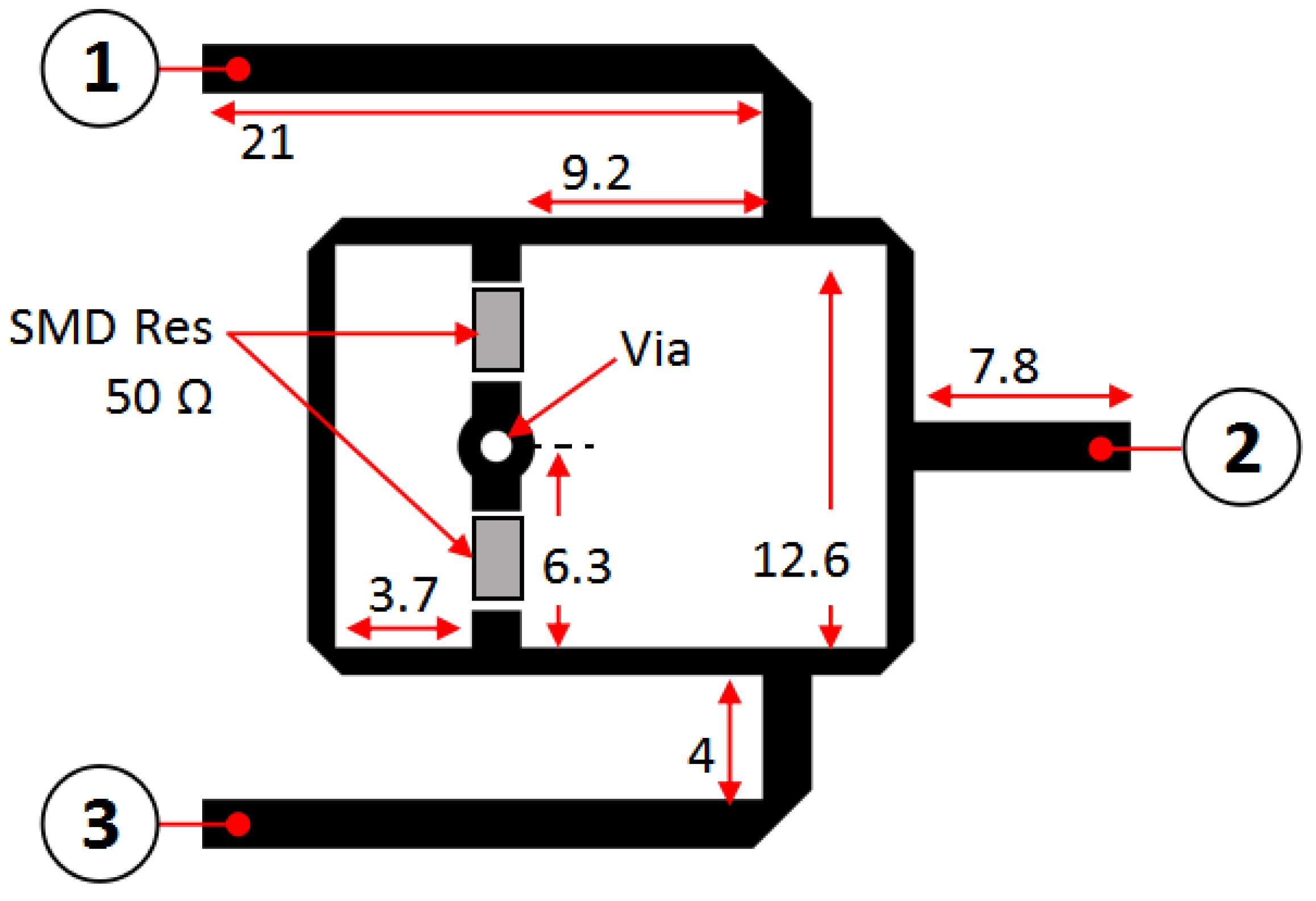
| Impedance | Width | Length () |
|---|---|---|
| = 50 | 1.6 mm | 10.4 mm |
| = 35.15 | 0.9 mm | 10.6 mm |
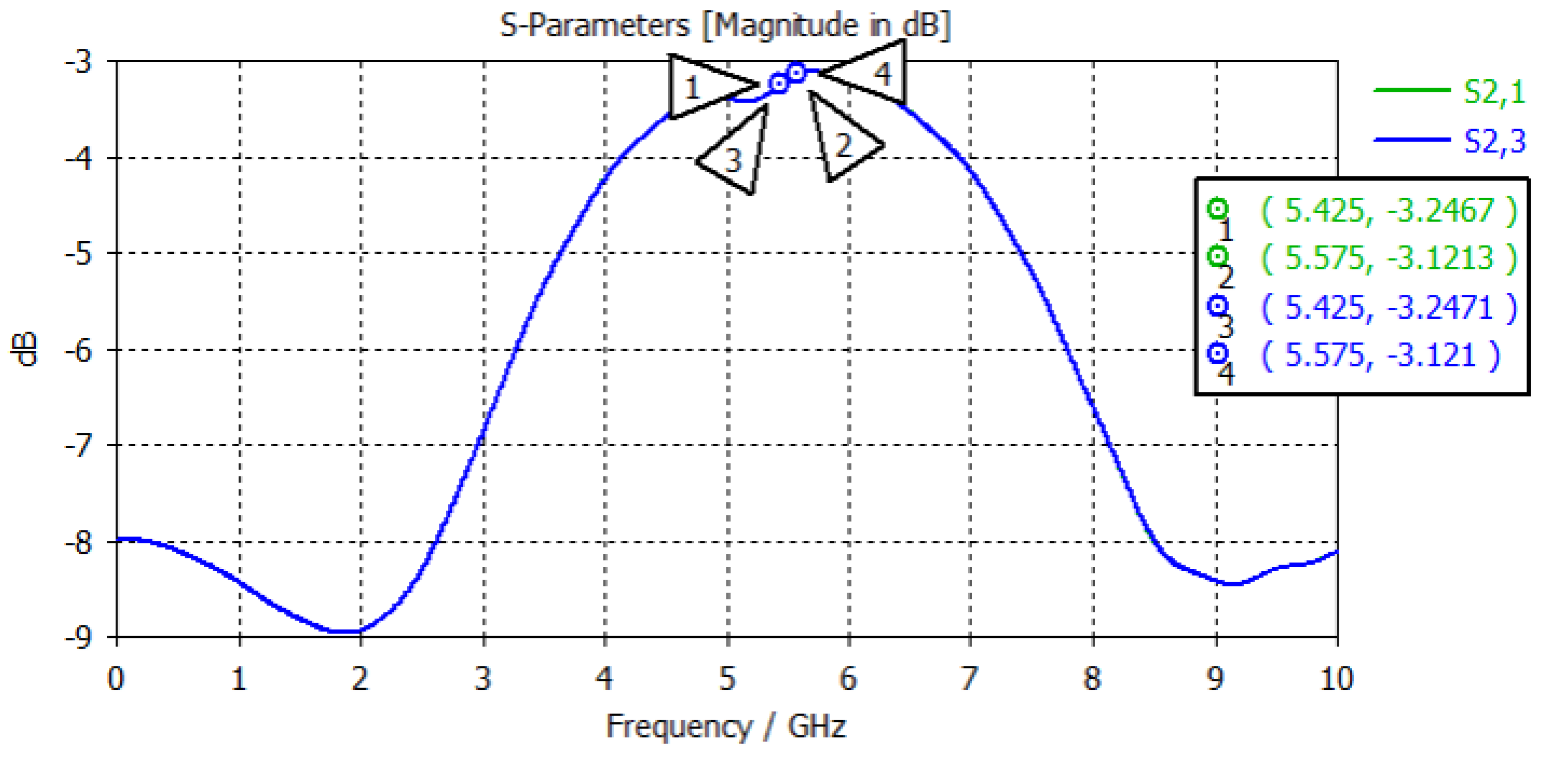
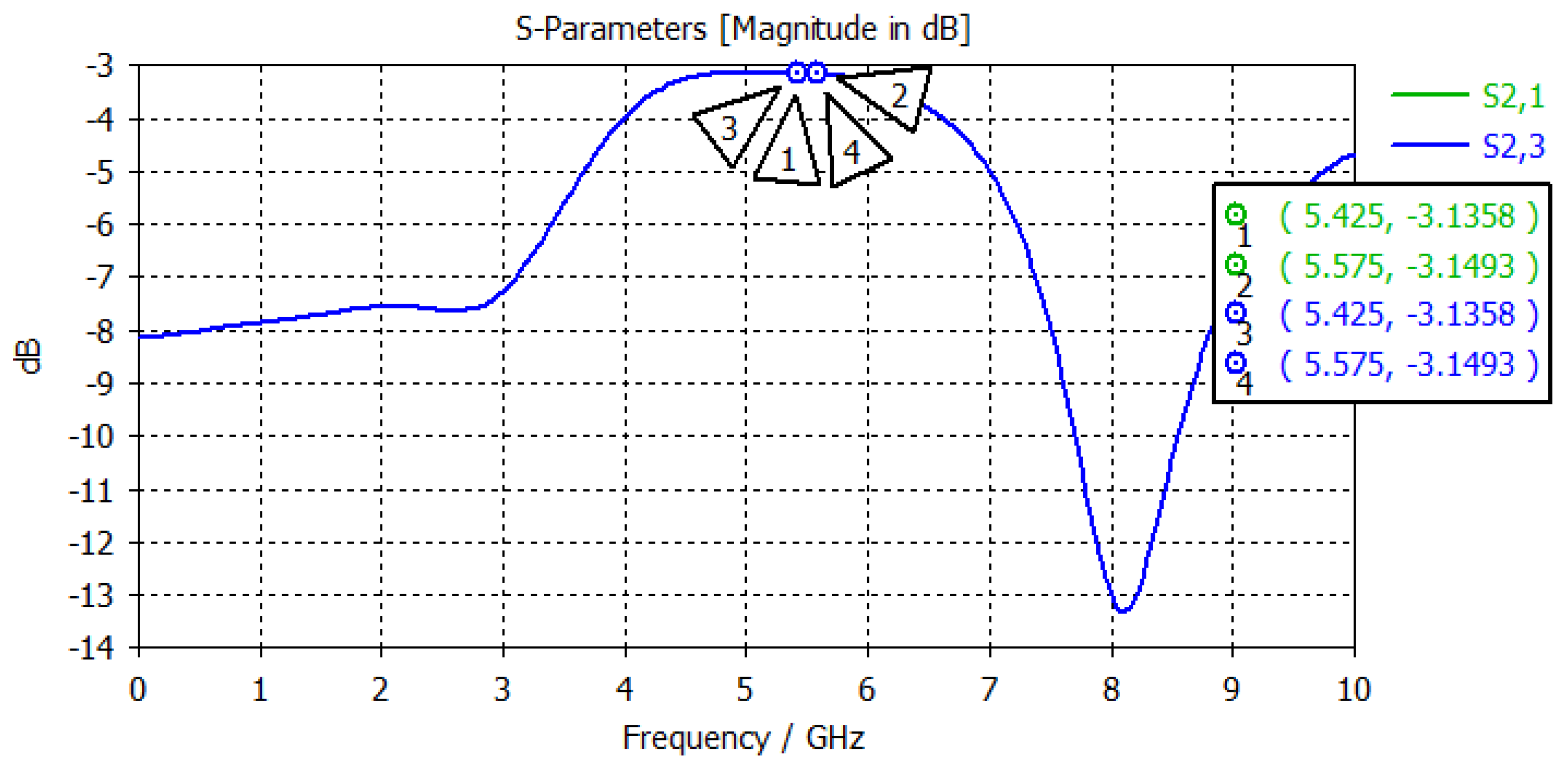
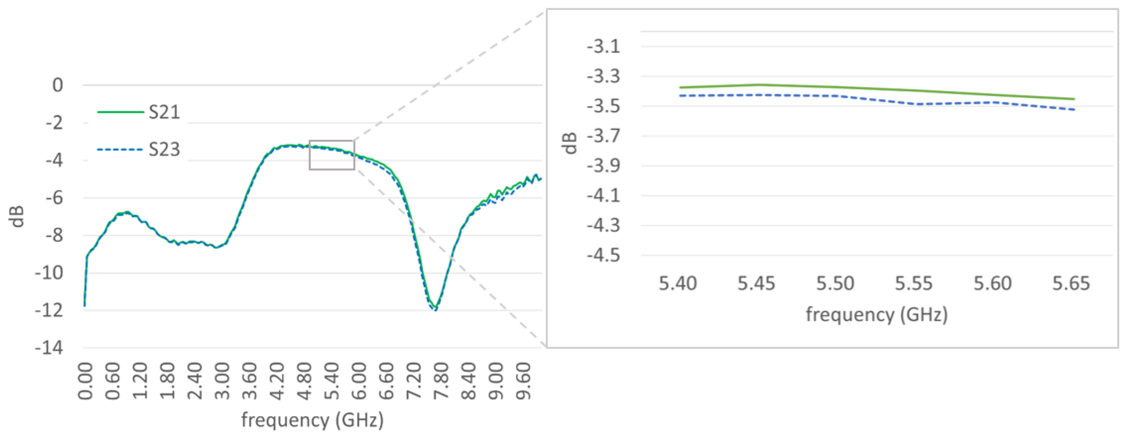
| Parameter | 5.425 GHz | 5 GHz | 5.575 GHz |
|---|---|---|---|
| −3.411 dB | −3.443 dB | −3.427 dB | |
| −3.453 dB | −3.492 dB | −3.482 dB | |
| Amplitude Unbalance | 0.042 dB | 0.049 dB | 0.055 dB |
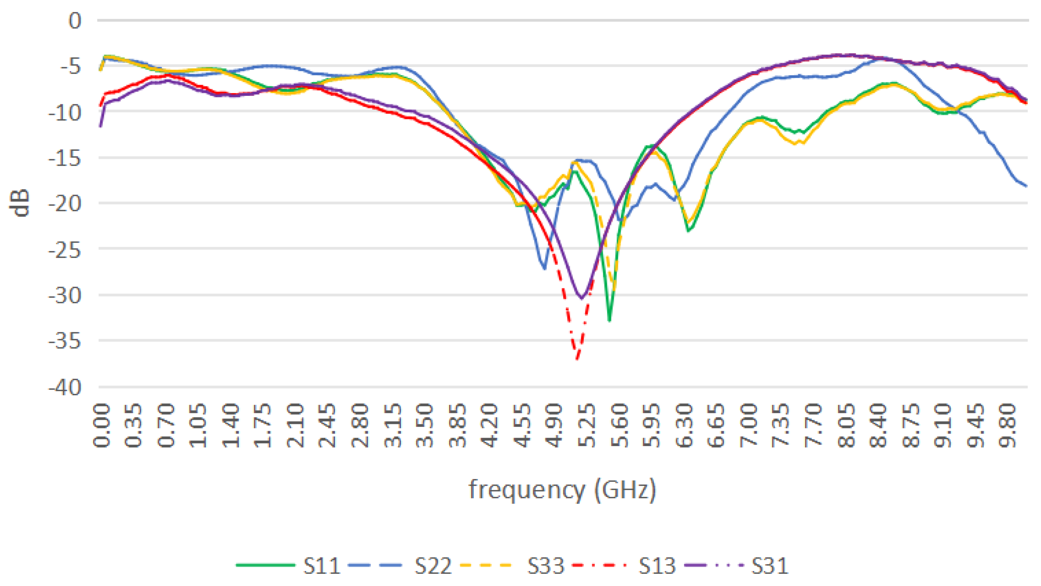
| −26.20 dB | −32.79 dB | −26.33 dB | |
| −17.35 dB | −18.80 dB | −20.81 dB | |
| −24.41 dB | −22.17 dB | −20.43 dB | |
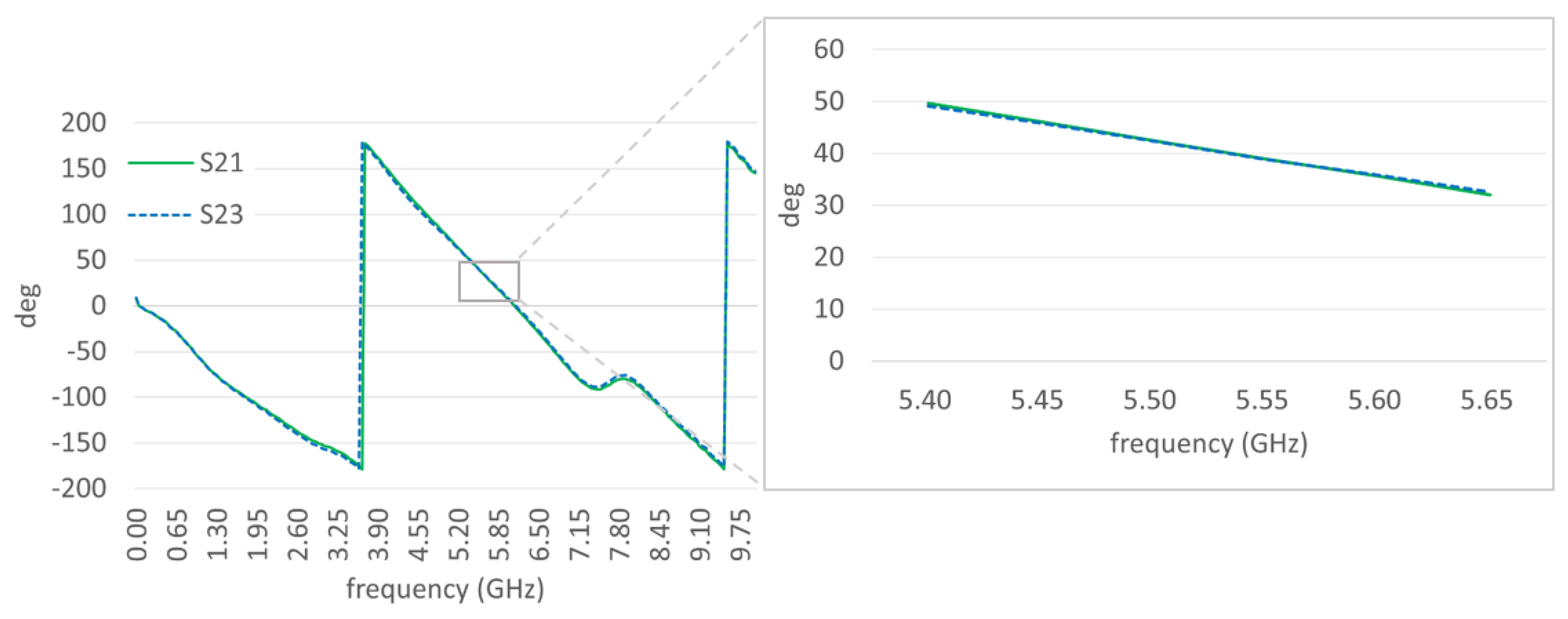
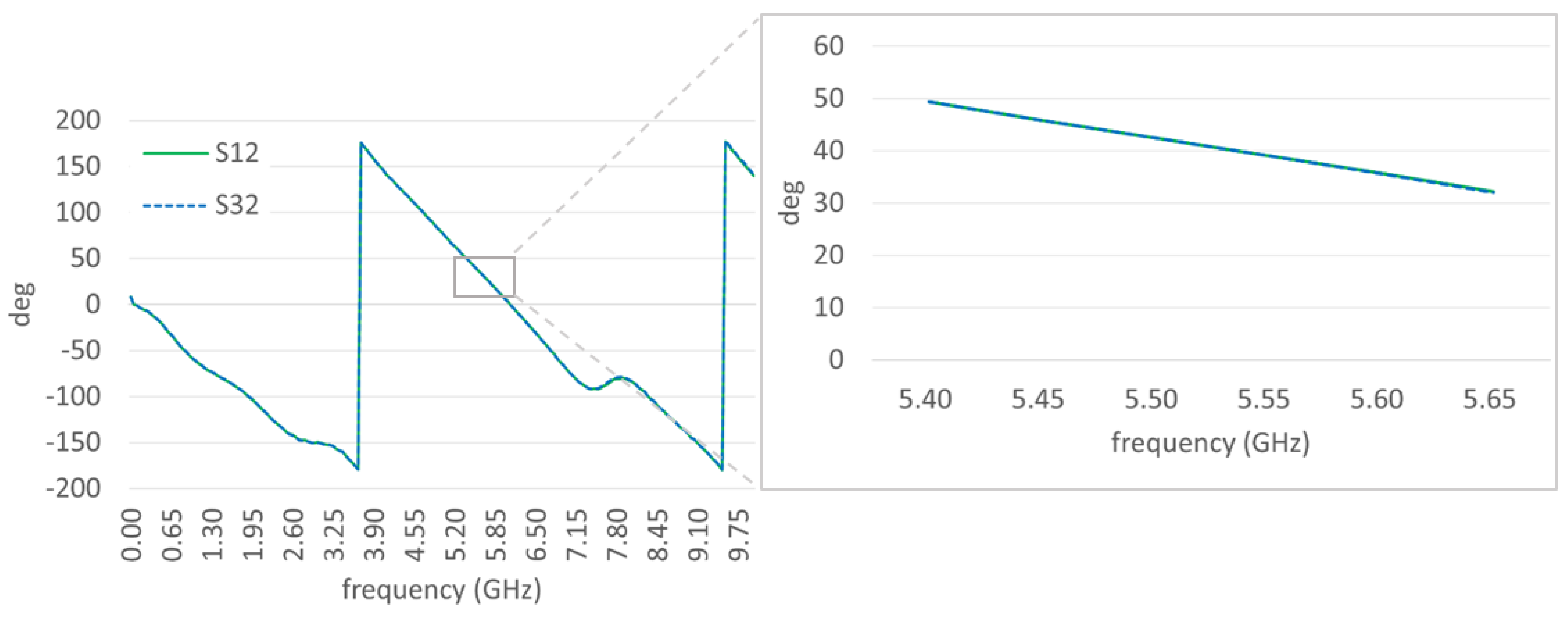
| 47.60 | 42.48 | 37.39 | |
| 47.58 | 42.41 | 37.34 | |
| Phase Unbalance | 0.02 | 0.07 | 0.05 |
| Part Number | Type | Frequency (GHz) | Amplitude Unbalance (dB) | Phase Unbalance (°) | Insertion Loss (dB) | Isolation (dB) |
|---|---|---|---|---|---|---|
| PD-0R510 [23] | WPD | 0.5–10 | 0.1 | 1 | 3.9 | 22 |
| PD-0109 [24] | WPD | 1–9 | 0.1 | 1 | 3.75 | 22 |
| PE2026 [25] | WPD | 2–8 | 0.06 | 3 | 3.4 | 20 |
| PE2063 [26] | Resistive | DC–12.4 | 0.4 | 2 | 6 | - |
| ZFRSC-123-S+ [27] | Resistive | DC–12 | 0.11 | 1.4 | 9.5 | 19.5 |
| ZX10R-2-183-S+ [28] | Resistive | DC–12 | 0.2 | 2 | 6.9 | 26 |
| This Research | Coupler | 5.5 | 0.049 | 0.07 | 3.47 | 22.17 |
Disclaimer/Publisher’s Note: The statements, opinions and data contained in all publications are solely those of the individual author(s) and contributor(s) and not of MDPI and/or the editor(s). MDPI and/or the editor(s) disclaim responsibility for any injury to people or property resulting from any ideas, methods, instructions or products referred to in the content. |
© 2024 by the authors. Licensee MDPI, Basel, Switzerland. This article is an open access article distributed under the terms and conditions of the Creative Commons Attribution (CC BY) license (https://creativecommons.org/licenses/by/4.0/).
Share and Cite
Ruhiyat, A.; Kurniawan, F.; Apriono, C. A Power Combiner–Splitter Based on a Rat-Race Coupler for an IQ Mixer in Synthetic Aperture Radar Applications. Remote Sens. 2024, 16, 2386. https://doi.org/10.3390/rs16132386
Ruhiyat A, Kurniawan F, Apriono C. A Power Combiner–Splitter Based on a Rat-Race Coupler for an IQ Mixer in Synthetic Aperture Radar Applications. Remote Sensing. 2024; 16(13):2386. https://doi.org/10.3390/rs16132386
Chicago/Turabian StyleRuhiyat, Abdurrasyid, Farohaji Kurniawan, and Catur Apriono. 2024. "A Power Combiner–Splitter Based on a Rat-Race Coupler for an IQ Mixer in Synthetic Aperture Radar Applications" Remote Sensing 16, no. 13: 2386. https://doi.org/10.3390/rs16132386
APA StyleRuhiyat, A., Kurniawan, F., & Apriono, C. (2024). A Power Combiner–Splitter Based on a Rat-Race Coupler for an IQ Mixer in Synthetic Aperture Radar Applications. Remote Sensing, 16(13), 2386. https://doi.org/10.3390/rs16132386