Review

Classical and Atomic Gravimetry

1
Innovation Academy for Precision Measurement Science and Technology, Chinese Academy of Sciences, Wuhan 430071, China
2
Wuhan Institute of Quantum Technology, Wuhan 430206, China
3
Hefei National Laboratory, Hefei 230094, China
4
University of Chinese Academy of Sciences, Beijing 100049, China
5
School of Information Engineering, Nanchang University, Nanchang 330031, China
*
Author to whom correspondence should be addressed.
Remote Sens. 2024, 16(14), 2634; https://doi.org/10.3390/rs16142634
Submission received: 21 May 2024 / Revised: 26 June 2024 / Accepted: 12 July 2024 / Published: 18 July 2024

Abstract

:
Gravity measurements have important applications in geophysics, resource exploration, geodesy, and inertial navigation. The range of classical gravimetry includes laser interferometer (LI)-based absolute gravimeters, spring relative gravimeters, superconducting gravimeters, airborne/marine gravimeters, micro-electromechanical-system (MEMS) gravimeters, as well as gravity satellites and satellite altimetry. Atomic gravimetry is a new absolute gravity measurement technology based on atom interferometers (AIs) and features zero drift, long-term stability, long-term continuous measurements, and high precision. Atomic gravimetry has been used to measure static, marine, and airborne gravity; gravity gradient; as well as acceleration to test the weak equivalence principle at the China Space Station. In this paper, classical gravimetry is introduced, and the research progress on static and airborne/marine atomic gravimeters, space AIs, and atomic gravity gradiometers is reviewed. In addition, classical and atomic gravimetry are compared. Future atomic gravimetry development trends are also discussed with the aim of jointly promoting the further development of gravity measurement technologies alongside classical gravimetry.

1. Introduction

The gravity measurements of the Earth’s gravity field are obtained through the measured physical quantity of acceleration due to gravity. The gravity field is an inherent physical field of the Earth that indicates the distribution and movement of materials within it and affects the motion of all objects. Thus, gravity measurements find wide applications in geophysics, resource exploration, geodesy, and inertial navigation. For example, in geophysics, gravity measurements have contributed to revealing the inner structure of the Earth [1]; in resource exploration, gravity data are used to prospect for oil and minerals or monitor water [2]; in geodesy, the gravity field of the Earth is one of the major topics. In inertial navigation, gravity data can increase the accuracy of navigation and positioning [3,4]. Various gravity measurement technologies, such as laser interferometer (LI)-based absolute, spring, superconducting, airborne/marine, and micro-electromechanical-system (MEMS) gravimeters; gravity satellites; and satellite altimetry have been developed owing to the importance of gravity measurements in both fundamental scientific research and engineering applications. Herein, these gravity measurement technologies are referred to as classical gravimetry. These technologies have been used in many applications, all having their own advantages and limitations. Classical gravimetry techniques are usually used complementarily. For example, LI-based absolute gravimeters can be used to calibrate spring gravimeters and superconducting gravimeters [5,6]. Airborne/marine gravimeters are used to rapidly measure gravity in areas such as mountains, deserts, and oceans as a supplement to the terrestrial measurements. By combining the gravity data from terrestrial and airborne measurements, gravity satellites, and satellite altimetry, high-resolution Earth Gravitational Models can be built, such as the Earth Gravitational Model 2008 (EGM2008) and EGM2020 [7].
Classical gravimetry is widely used, but new gravity measurement technologies must also be developed. Atom interferometers (AIs) are high-precision instruments that can measure gravity [8,9], gravity gradient [10], and rotation [11]. AIs have a wide variety of applications such as in the measurements of inertia, the fine-structure constant [12,13], and Newtonian gravitational constant G [14]; in the testing of the weak equivalence principle [15,16]; and in detecting gravitational waves [17,18,19]. AI-based gravimetry has rapidly developed in recent years. In quiet environments, atomic gravimeters achieved a sensitivity of 2.2–20 μGal/ Hz (1 μGal = 10−8 m/s2) [20,21,22,23,24], a long-term stability of 0.05 μGal [21], and an accuracy of 2–5.2 μGal [20,22,25,26,27]; precision below 1 mGal was achieved in marine gravity measurements [28]. Atomic gravimeters are not affected by drift, so they are especially suitable for deep-sea gravity measurements. Airborne gravity measurement errors ranging from 0.6 to 1.3 mGal were estimated in an airborne gravity survey [29]. The measurement error here depends on the flight conditions and filtering used. Several compact atomic gravity gradiometers (AGGs) have been developed to perform vertical gravity gradients. A resolution of 5 E (1 E = 1 × 10⁻⁹ s−2) after a 100 s integration time and long-term stability below 0.15 E @ 110,000 s were obtained [30]. The systematic errors of an AGG were evaluated and corrected, and the local gravity gradient was measured as 3114(53) E by this AGG [31]. An AGG for horizontal gravity gradient measurements with a sensitivity of 60 E/ Hz was reported [32]. Atomic interferometry was also tested in a sounding rocket [33,34] at the International Space Station [35,36,37] and at the China Space Station [38,39]. The most important scientific objective of the AI at the China Space Station is testing the weak equivalence principle. An acceleration measurement resolution of 1.03 × 10⁻⁶ m/s2 for a single measurement was achieved by this AI, and the rotation was measured with a precision in the order of 10−5 rad/s; the precision was mainly limited by the small interference loop area [39]. AIs show potential for many additional applications. In this review, classical and atomic gravimetry are introduced and compared. The development trends in atomic gravimetry are also presented.
The remainder of this paper is organized as follows: Section 2 introduces the classical gravimetry techniques. In Section 3, the progress of atomic gravimetry research is reviewed. In Section 4, classical and atomic gravimetry are compared. Finally, the review conclusion and discussion for this field are presented in Section 5.

2. Classical Gravimetry

Gravity measurements date back to the period of Galileo, who found that the travel distance of objects in free fall is proportional to the square of time and that the square of the period of a pendulum varies directly with the pendulum length. Galileo thus pioneered the methods used for gravity measurement [40]. The pendulum was long used to measure gravity, having an accuracy limit of approximately a few parts per 106 [41]. The pendulum was eventually replaced by gravimeters based on the direct free-fall and symmetrical rise and fall of a macroscopic test mass [42,43], which obtained very accurate measurements. Springs can balance the weight of a test mass, and the elongation of a spring varies with the acceleration due to gravity. Based on this principle, spring relative gravimeters were developed for field surveys. Very highly sensitive superconducting gravimeters were also developed. Additionally, airborne/marine gravimeters were built to rapidly measure gravity on an aircraft or a ship. It is also important to obtain global gravity data, which has been obtained using models that combine the ground gravity data and various satellite measurements such as those from satellite laser ranging, dedicated gravity satellites, and satellite altimetry. The spatial resolution of gravity satellites is low, approximately a few hundred kilometers. Marine gravity fields can be recovered from satellite altimetry data. The spatial resolution of the recovered gravity field is much higher than that of gravity satellites. MEMS gravimeters are a new type of gravimeters which are based on the mass–spring system, low cost, small, and mass-producible. In the following section, we introduce the classical gravimetry techniques, including LI-based absolute, spring, superconducting, MEMS, and airborne/marine gravimeters; dedicated gravity satellites; and satellite altimetry. The pendulum and the rise-and-fall gravimeters with a macroscopic test mass are omitted owing to their rare use in current high-precision gravity measurements.

2.1. LI-Based Absolute Gravimeters

Absolute gravimeters directly measure the acceleration due to gravity and are used to establish gravity references and calibrate relative gravimeters. The main type of absolute gravimeter in current use is the free-fall gravimeter, which is based on the LI [44]. This type of gravimeter developed into a mature product (FG5) circa 1990. In these gravimeters, a test mass (corner-cube mirror) freely falls through a vacuum; thus, gravity can be highly accurately measured by precisely measuring the fall distance with an LI and the fall time with an atomic clock, as shown in Figure 1a. Free-fall gravimeters directly measure gravity in standard length and time units, thereby providing absolute gravity acceleration measurements [45]. Vibrations may cause errors in the measurements but are effectively suppressed using supersprings. The FG5 gravimeter has a sensitivity of up to 15 μGal/ Hz and a nominal accuracy of 2 μGal in quiet environments. The set scatter of the measurement results is in the order of 1 μGal according to the FG5 brochure for a 24 h measurement [46]. However, some studies showed that the accuracy of this gravimeter is realistically approximately 3–4 μGal [47]. Mechanical wear occurs because the test mass is a corner-cube mirror, which hinders continuous long-term gravity measurements. Another LI-based absolute gravimeter is the A10 gravimeter, which is closely related to FG5, as shown in Figure 1c. Compared with the FG5, the A10 gravimeter is more portable, durable, and environmentally adaptable, and is suitable for gravity measurements in the field, having a nominal accuracy of 10 μGal [48].
LI-based absolute gravimeters use LIs to measure the falling distance; thus, the accuracy of these gravimeters strongly depends on the laser frequency accuracy. The laser frequency must be regularly tested to correct the systematic error it causes. The accuracy of an absolute gravimeter also cannot be separately tested. The international comparisons of absolute gravimeters (ICAGs) are regularly conducted, approximately every four years, to verify the consistency of the gravimeter measurement results and to intercompare absolute gravimeters. For example, the 10th ICAG was conducted at the National Institute of Metrology, China, in 2017 [49].

2.2. Spring Relative Gravimeters

A spring gravimeter is a type of relative gravimeter that measures differences and changes in gravity. The springs are composed of metal or quartz. Both metal and quartz spring gravimeters are portable and durable, easy to deploy, suitable for field observation, and widely used. In a metal-spring gravimeter, a test mass is suspended from a spring. The elongation of the spring is related to the magnitude of gravity. Thus, gravity can be determined by measuring the elongation of the spring combined with the coefficient of elasticity and the test mass. The elastic coefficient of the spring and the test mass must be known; therefore, spring gravimeters do not measure gravity in standard time and length units. This is the difference between relative and absolute gravimeters [45]. Springs performance is temperature dependent, and effects such as aging, creep, hysteresis, fatigue, memory, and magnetization can lead to drifts and measurement errors. The precision of a gravimeter depends on the precision of the spring elongation measurements. Compared to vertical spring suspension, zero-length spring suspension can amplify the elongation caused by gravity and are therefore more sensitive. This can significantly reduce the required spring elongation measurement precision [45]. Figure 2a shows a schematic of a zero-length spring suspension. High-precision spring gravimeters were developed with this suspension. This type of gravimeter remains one of the primary spring gravimeters. The gPhoneX gravimeter from Micro-g LaCoste, Lafayette, CO, USA is based on the zero-length spring suspension and the manufacturer announces a precision of 1 μGal with a drift of approximately 1.5 mGal/month, or less than 500 μGal/month typically [50]. The gPhoneX gravimeter from Micro-g LaCoste is shown in Figure 2b; as a type of relative gravimeter, regular calibrations and drift estimations are required for it.
Quartz-spring gravimeters are another type of spring gravimeter. Quartz has suitable elastic properties, so quartz-spring gravimeters do not need to be clamped during transportation; thus, the structure and operation of these gravimeters are simpler. In addition, quartz is insensitive to magnetic fields and can be easily manufactured. In 1990, Scintrex Ltd., Ontario, Canada developed a high-precision quartz-spring gravimeter that adopted advanced electronics. This quartz-spring gravimeter used a capacitor to measure the displacement of the test mass, and the capacitor voltage was controlled through a feedback loop to compensate for the displacement of the test mass. Thus, the position of the test mass remained unchanged. Gravity was calculated using the feedback voltage [52], and the gravimeter was almost fully automated. A zero-length spring suspension is not required in quartz-spring gravimeters because high-precision displacement measurements are obtained with the capacitor. The precision of a quartz-spring gravimeter is limited by the low density of quartz and the low test mass. In addition, quartz has thermal properties that can lead to large drifts [47]. The CG6 gravimeter from Scintrex is a typical quartz-spring gravimeter. The standard deviation of gravity measurements at a site is less than 5 μGal and the uncompensated drift is less than 200 μGal/day according to the CG6 brochure [51]. The CG6 gravimeter is shown in Figure 2c.

2.3. Superconducting Gravimeters

Superconducting gravimeters are also relative gravimeters; however, they are super-stable and super-precise, and provide super-low noise, so they are particularly suitable for continuous long-term (years to decades) gravity observations. Superconducting gravimeters use magnetic levitation instead of mechanical springs. Superconducting currents can produce an extremely stable magnetic levitation force that cannot be achieved using mechanical springs. The gravity measurement unit consists of three parts: a superconducting levitated sphere, magnetic field coils, and a magnetic shield. Changes in gravity lead to a displacement of the levitated sphere, which is measured using a capacitance bridge. A small magnetic gradient is generated by the magnetic field coil, so a slight change in gravity can cause a large displacement; thus, this type of gravimeter is highly precise. The magnetic gradient is equivalent to the elastic coefficient of the mechanical spring, and the magnetic shield is used to protect against external magnetic fields. The magnetic field generated by the feedback coils holds the levitated sphere at the zero position of the capacitor bridge, which extends the linear dynamic range and increases the response speed. A vacuum tank containing the gravity measurement unit is immersed in liquid helium at 4 K to maintain superconductivity. All materials are stable at low temperatures; therefore, effects such as material creep and changes in properties with humidity and temperature do not occur in superconducting gravimeters [53]. The power consumption of such gravimeters is high (more than 1 kW) because of the need to generate a low temperature. GWR Instruments, Inc, San Diego, CA, USA produces two types of superconducting gravimeters. The first is a station-based superconducting gravimeter with a resolution of 1 nGal and a drift as low as a few μGal/year [54,55]. The second is a transportable superconducting gravimeter (iGrav SG), which has a resolution of 0.3 μGal after averaging data over 2 min and a drift of less than 0.5 μGal/month according to the datasheet [56]. Figure 3 shows the iGrav SG.

2.4. Airborne/Marine Gravimeters

Airborne or marine gravimeters are used on aircraft or ships, respectively, to measure gravity. In dynamic environments, gravity and kinematic accelerations superimpose, which must be separated in the acceleration measurements of gravity sensors. Typically, the gravity sensors of classical airborne or marine gravimeters are spring gravimeters or accelerometers. Kinematic acceleration includes two components: the motional carrier and Eötvös accelerations. Fluctuations in the motional acceleration of an aircraft can reach 10 m/s2 during turbulence, and can be below 0.3 m/s2 when the aircraft is stable [58]. The fluctuation in the motional acceleration on a ship may reach 5 m/s2 e.g., [28]. The motional acceleration of an aircraft and a ship is primarily distributed over a period of 1–300 s and 2–20 s, respectively [59]. The motional acceleration of ships is generally deducted using low-pass filtering, and that of aircraft is calculated by the second derivative of height. The Eötvös acceleration is determined by the rotational rate of the Earth, latitude of the measurement points, and altitude and velocity of the carrier, and so can be computed using position and navigation information.
The precision of an airborne/marine gravimeter is related to the dynamic environment and is generally in the order of 1 mGal [60,61,62]. The spatial resolution of gravity data is determined by the carrier speed and filtering time. The spatial resolution of airborne and marine gravimeters is approximately 4–6 km and lower than 2 km, respectively [59,60]. In dynamic environments, the direction of the sensitive axis of gravity sensors varies with the carrier and can cause measurement errors if ignored. Airborne/marine gravimeters are divided into two types: platform-based and strapdown. In a platform-based gravimeter, the gravity sensor is fixed on an inertial stabilization platform. The inertial stabilization platform is used to control the direction of the sensitive axis of the gravity sensor and maintain consistency with the direction of gravity. Strapdown gravimeters do not require an inertial stabilization platform and use the three-axis rotation and acceleration signal output from an inertial measurement unit to calculate gravity. Strapdown gravimeters are relatively small owing to the lack of a stabilization platform [63]. The GT-2A airborne gravimeter [64] from Canadian Micro Gravity Ltd., Aurora, ON, Canada, the SEA III marine gravimeter [65] from Micro-g LaCoste and the CHZ-II gravimeter from the Institute of Precision Measurement of the Chinese Academy of Sciences, Wuhan, China (APM) [66] are platform-based gravimeters, whereas the SAG-2M gravimeter [62] from Beijing Institute of Aerospace Control Devices, Beijing, China, and the SGA-WZ gravimeter [67] from the National University of Defense Technology, Changsha, China are strapdown gravimeters. The gravity sensors in classical airborne/marine gravimeters are either spring gravimeters or accelerometers; therefore, calibrations and drift estimations are required. The drift of GT-2A is less than 0.1 mGal/day and the drift of SEA III is about 0.1 mGal/day according to their datasheets [64,65]. Drift accumulates during deep-sea gravity measurements, resulting in gravity measurement errors. Figure 4 shows the GT-2A airborne gravimeter, SEA III marine gravimeter, and SGA-WZ strapdown gravimeter.

2.5. MEMS Gravimeters

Micro-electromechanical-system (MEMS) gravimeters are miniaturized relative gravimeters developed based on semiconductor technologies. MEMS gravimeters have attracted wide interest as they have a low cost and are small and mass-producible, showing promise in the fields of geophysics and resource exploration, especially in harsh environments such as those experienced during down-borehole exploration and volcanic activity monitoring. The basic working principle of MEMS gravimeters is similar to that of most MEMS sensors, in which a spring–mass system is used to transduce accelerations. In 2016, Middlemiss et al. used a high-performance MEMS accelerometer for gravity measurements and successfully measured Earth tides with the first prototype of a MEMS gravimeter [68].
MEMS gravimeters can be classified into two categories according to the type of transduction method used. The first type has a displacement-sensing mechanism. Variation in gravity leads to the displacement of the test mass. Therefore, gravity can be obtained via the means of displacement sensing. Typically, displacement is measured using an optical sensor or a capacitive transducer. The sensitivity of a MEMS gravimeter is inversely proportional to the k/m ratio of the microstructure, where k is the elastic coefficient of the spring and m is the mass of the proof mass. Thus, a low elastic coefficient and a large mass help to increase the sensitivity. Several MEMS mechanisms, such as the geometric anti-spring system (as shown in Figure 5a) and spring–mass system with a curved beam and two folded beams, have been developed to decrease the elastic coefficient k [68,69]. Currently, the sensitivity of MEMS gravimeters based on displacement sensing is 0.25 to 40 μGal/√Hz at 1 Hz [68,69,70,71,72,73]. Earth tides have been observed with these gravimeters after deducting the drifts ranging from under 150 μGal/day to 2.4 mGal/day for different MEMS gravimeters [68,69]. A dynamic range from 975 to 983 Gal with a high sensitivity of 8 μGal/√Hz was achieved by Tang et al., indicating that MEMS gravimeters have the ability to measure gravity variations worldwide [69].
The second type of MEMS gravimeter is the resonant MEMS gravimeter, which uses the correlation between the resonant frequency of the mechanical resonator and the variation in gravity. For this type of MEMS gravimeter, the proof mass is usually connected to a vibrating beam, as shown in Figure 5b. The vibrating beam is driven by an electrostatic actuation, and the natural frequency of the vibrating beam is proportional to the magnitude of gravity. By monitoring the motion of the vibrating beam with a capacitive transducer and analyzing the resonant frequency variations, the varying gravity signal can be obtained. The force on the beam induced by gravity can be amplified by the lever mechanism between the proof mass and the vibrating beam, which increases the sensitivity of the gravimeters. In addition, a differential measurement is implemented given two identical vibrating beams linked with the proof mass on two sides, which doubles the scale factor and suppresses some common-mode noise [74,75]. A differential vibrating beam MEMS gravimeter achieved an output Allan deviation of 9 μGal for a 1000 s integration time and a noise floor of 100 μGal/√Hz [74]. The results of the finite element simulations indicated that resonant MEMS gravimeters can have a dynamic range as large as ±5 g [75]. Additionally, a commercial resonant MEMS gravimeter (GRAV10) from Silicon Microgravity Limited, Waterbeach, UK achieved a resolution of less than 10 μGal and a residual drift after compensation of 50 μGal/day, with dimensions of 25 cm × 25 cm × 25 cm according to the datasheet [76,77].
Overall, relative MEMS gravimeters are highly sensitive, 0.25 to 100 μGal/√Hz, and have been successfully applied for measuring Earth tides [68,69,70,71,72,73,74,75]. The compact design and the promising capability make them good candidates for applications requiring low-cost and large-scale deployment.

2.6. Dedicated Gravity Satellite Missions

Gravity satellites, which provide global coverage, are also used for gravity surveys. The first dedicated gravity satellite was the Challenging Minisatellite Payload (CHAMP). One of its objectives was to measure the long-wave components of the Earth’s gravity field (>800 km). The mission period was from July 2000 to September 2010. CHAMP operated in a low orbit from 260 km to 454 km and was equipped with a GPS receiver and a high-precision accelerometer. The GPS receiver received signals from high-orbit satellites and provided the positional information to the CHAMP satellite using high–low satellite tracking technology. The accelerometer precisely measured the non-gravitational accelerations of the satellite such as solar radiation, Earth albedo, and air drag [78]. Gravity is the first derivative of gravity potential, and the gravity field can be analytically modeled and represented as a spherical harmonic expansion with a series of spherical harmonic coefficients [79]. From the satellite position information and the accelerometer data, the coefficients can be solved to a certain degree, and a gravity field model of the Earth can be established. The higher the degree of the coefficients, the more high-frequency information is reflected in the gravity field model.
The second dedicated gravity satellite mission was the Gravity Recovery and Climate Experiment (GRACE). The mission period was from March 2002 to December 2017, and its main objective was to measure the time-varying gravity field monthly or weekly to monitor changes in the mass distribution of the Earth. The plan was to map the global gravity field with high precision and for spatial scales ranging from 400 to 4000 km every 30 days [80]. GRACE was composed of two satellites in the same orbit 220 ± 50 km apart, with an initial orbital altitude of 500 km. The inter-satellite distance was measured using a high-precision (μm-level) microwave ranging system and contained important gravity information on short and medium wavelengths. Each satellite was equipped with a high-precision accelerometer that monitored the non-gravitational acceleration and a GPS receiver that accurately measured the position of the satellite (centimeter-level). GRACE Follow-On, a successor to GRACE, was launched in May 2018 and will continue to measure the time-varying gravity field [81].
The third dedicated gravity satellite was the Gravity Field and Steady-State Ocean Circulation Explorer (GOCE), whose mission period was from March 2009 to November 2013, and the goal was to obtain as detailed and accurate a gravity field as possible and establish a gravity field model with a spatial resolution of approximately 100 km (half wavelength) and an accuracy of 1 mGal [82]. The gravity field signal attenuates with orbital altitude. The initial orbital altitude of GOCE was set to only 255 km to reduce this effect. The satellite was equipped with a GPS receiver and a gravity gradiometer. The GPS receiver provided centimeter-level positional information for obtaining gravity information in long-wavelength components. The gravity gradient, which is sensitive to high-frequency gravity information, is the second derivative of the gravity potential. Gravity gradient data were used to obtain high-frequency gravity information. GOCE combined high–low satellite tracking and gravity gradient measurement technology to complementarily measure the Earth’s gravity field. Several series of gravity field models have been published [83,84].

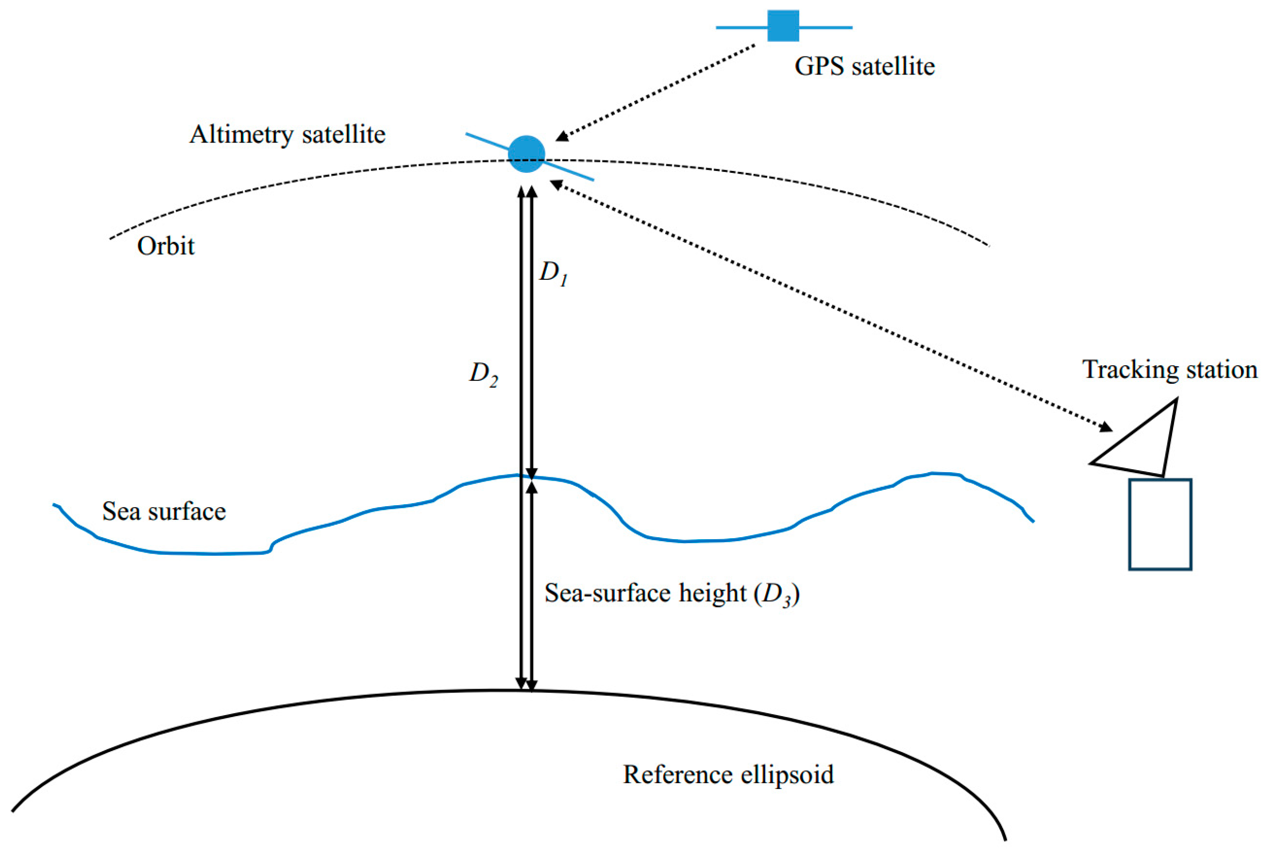
2.7. Satellite Altimetry

Satellite altimetry involves the use of a radar altimeter on a satellite to measure the distance D1 of a satellite from the sea surface, and GPS or another tracking technology is used to measure the distance D2 of the satellite from a reference ellipsoid. After correcting for errors such as the radar signal propagation delay, the distance D3 of the sea surface relative to the reference ellipsoid (sea-surface height) can be calculated, as shown in Figure 6. Subsequently, the gravity field is deduced from the sea-surface height by solving the vertical deflection or using other methods [85,86]. The gravity field in an oceanic area can be obtained from satellite altimetry data owing to the high radar reflectivity of the sea surface.
The accuracy of the gravity field obtained from satellite altimetry depends on the altimetry accuracy, altimetry data spatial density, and the diversity of satellite orbit inclination angles. For example, to deduce a gravity field with an accuracy of 1 mGal and a spatial resolution of 28 km, the accuracy of the vertical deflection must be 1 μrad at a 7 km distance for a sea-surface measurement accuracy of 7 mm (1 s time data average). The Geosat altimetry satellite (launched in 1985), ERS-1 (1991), Topex/Poseidon (1992), and ERS-2 (1995) had altimetry accuracies of 30–40 mm, corresponding to the gravity measurement accuracies of 4–6 mGal [87]. The altimetry accuracy of Jason-1 (2001) and CryoSat-2 were 1.25-fold higher than those of Geosat and ERS-1 e.g., [1]. The spatial density of satellite altimetry data is primarily determined by the duration of the satellite’s operation in orbit. Before the launch of GEOSAT and ERS-1, many altimetry satellites were launched, and large amounts of altimetry data were obtained, but only a small amount of data reached sufficient spatial density [87]. Only with the launches of GEOSAT and ERS-1 were large amounts of altimetry data with sufficient spatial density obtained. The GEOSAT ground trajectory spacing at the regional equator was 6 km, whereas that of the ERS-1 was 8.2 km. From the GEOSAT and ERS-1 altimetry data, a high-spatial-resolution marine gravity field DNSC08GRA (Andersen, Knudsen, and Berry) was obtained. In 2010, DNSC08GRA gravity data were compared with 321,400 ocean observations in the Gulf of Mexico. The average difference was 0.39 mGal with a standard deviation of 3.91 mGal [88]. CryoSat-2 provided 96 months of measurement data with a high trajectory density [89] and a ground trajectory spacing of approximately 3.5 km, the latter of which, obtained by Jason-1, was approximately 3.9 km [90]. Thus, accuracy was higher using CryoSat-2 and Jason-1 data. The inclination of the satellite orbit also affects the accuracy. The orbital inclination angle of the CryoSat-2 altimetry satellite was 88°, and the accuracy of the east–west component of the gravity field obtained with CryoSat-2 was approximately 1.5 times worse than that in the north–south direction. The orbital inclination angle of Jason-1 was 66°. This, combined with altimetry data from the Jason-1 satellite, substantially increased the accuracy of the east–west component of the gravity field [90]. In 2012, a marine gravity field inferred by data from the CryoSat-2, Envisat, and Jason-1 satellites was compared with ship surveys in the Gulf of Mexico and Canadian Arctic. In the Gulf of Mexico, the accuracy reached approximately 1.7 mGal, whereas in the Canadian Arctic, it was approximately 3.75 mGal [90]. In 2019, the V28 marine gravity field obtained by satellite altimetry was compared with ship survey data in the Gulf of Mexico, and the accuracy was approximately 1.23 mGal [89].
In non-open sea areas, such as coastal and polar regions, the accuracy of conventional satellite altimetry technology is low, leading to poor-quality gravity data. CryoSat-2 uses synthetic aperture radar technology to increase accuracy in these regions [91].

3. Atomic Gravimetry

AI-based atomic gravimetry is a new and promising gravity measurement technology characterized by zero drift and long-term stability, providing long-term continuous measurements and high precision. AIs were first realized in 1991 and have benefited from the developments in laser cooling and atom trapping. Physical particles have a wave–particle duality; atoms are wave-like and can interfere similar to light waves. Several techniques can be used for manipulating atoms and achieving atomic interference, such as stimulated Raman transition (SRT) [92], Bragg diffraction [93,94], double-slits [95], the diffraction gratings of light [96], and microstructure grating [97]. Of these, SRT is the most common. Most atomic gravimeters are based on AIs that use SRTs, using a Raman laser comprising two phase-coherent lasers that are far detuned from the excited state of atoms. The frequency difference between the two lasers is approximately equal to the frequency splitting between the two atomic ground states. Generally, the atoms are alkali metals, such as Na, 87Rb, 85Rb, and Cs. When a Raman laser interacts with atoms, the atoms transition between two ground states, |a> and |b>. The transition between the internal states and the momentum of the atoms is coupled, and the phase of the Raman laser is transferred to the atoms. When a π/2 pulse (Raman laser pulse) interacts with an atom, a 50% probability exists that an atom in the initial state |a> transitions to state |b>, and a 50% probability exists that an atom remains in state |a>. If the atom transitions to state |b>, it obtains the momentum of the Raman laser; if the atom remains in its initial state, momentum is not transferred. After some time, the atoms are split into two groups. When a π pulse interacts with the atoms, those in initial state |a> transition to state |b> with 100% probability, and those in initial state |b> transition to state |a>. The momentum of the Raman laser is transferred to the atoms during the transition; the momentum of the atoms changes, and the atoms reorient. The duration of the π pulse is twice that of the π/2 pulse, typically in the order of 10 μs.
A schematic of AIs using SRTs is shown in Figure 7. First, a cold atomic cloud is obtained via laser cooling and trapping, which is prepared in an initial state, such as state |a>. Second, the first Raman pulse (π/2) is activated, and the atomic cloud splits into two populations that evolve freely along two independent paths. After a period of time T, a second Raman pulse (π) is activated, and the atomic clouds reorient. After a second period T, a third Raman pulse (π/2) is activated. Thus, the atomic clouds combine for interference [98]. By detecting the population P of atoms in state |a> or |b>, the atomic interference fringes can be obtained. The population of atoms in state |b> after interference can be expressed as
Pb = P0 − 0.5C × cos(Φ),
where P0 is the mean of Pb, C is the contrast of the fringe, and Φ is the phase of AI (phase difference accumulated between the two interference paths). Φ can be obtained from the interference fringe.
If the above interference occurs in a gravity field, the cold atomic cloud freely falls. When the π/2-π-π/2 Raman pulses interact with the atomic clouds, the clouds experience different phases of the Raman laser, determined by the positions of the atomic clouds. This records the positional information of the atomic clouds. During SRTs, the phase of the Raman laser is transferred to and accumulates in the atomic clouds, which then contributes to phase Φ. In a uniform gravitational field, the phase Φ is expressed as e.g., [9]
Φ = φA − φB − φC + φD = keff gT2.
where keff is the effective wave vector of the Raman laser, with keff ≈ 4π/λ, and λ is the wavelength of the Raman laser; φA, φB, φC, and φD are the phases of the Raman laser when the atomic clouds interact with the π/2-π-π/2 Raman pulses. The sensitive axis of AIs is along the direction of the effective wave vector of the Raman laser. For atomic gravimeters, this sensitive axis is adjusted to align with gravity. The scale factor between phase Φ and acceleration due to gravity g is keff T2, which is stable and large. For example, for 87Rb atoms and T = 100 ms, keff T2 is approximately 1.6 × 10⁵ (m/s2)−1. Thus, AIs are highly sensitive to gravity and can obtain high-precision gravity measurements with long-term stability.
The sensitivities of AIs and LIs were theoretically compared [99]. Theoretically, the sensitivity of AI-based gravimeters is much higher than that of LI-based gravimeters because atoms have mass, and the cold atomic cloud is much slower than light. AIs use the Raman laser phase as a ruler to record the position of free-fall atomic clouds and combine the position with time to measure gravity. The measurement is directly related to the standard length and time units; therefore, AIs can measure absolute gravity acceleration. No mechanical wear occurs during operation because the test mass is a cold atomic cloud rather than a macroscopic mechanical object; thus, AIs can continuously operate for long periods. Equation (2) is derived assuming a uniform gravity field. In a non-uniform field, additional phases related to the gravity gradient must be considered e.g., [20]; however, this does not degrade the performance of atomic gravimeters.
Atomic gravimeters can be divided into static, dynamic, and space AIs according to their applications. In addition, AGGs based on AIs can measure gravity gradients.

3.1. Static Atomic Gravimeters

Atom interferometers using SRTs were first developed by Kasevich and Chu at Stanford University. In this AI, laser-cooled sodium atoms were vertically lofted in an atom fountain. After lofting, π/2-π-π/2 Raman pulses were applied to perform atom interference. Interference fringes were observed, and gravity was measured with a resolution of 3 × 10⁻⁶ after 1000 s of integration time from the interference fringe for T = 10 ms e.g., [8]. Subsequently, a Cs AI was developed by Chu et al. The interference time T was increased to 160 ms. Equation (2) shows that the longer the interference time T, the larger the scaling factor and the more sensitive the AI. The measurement noise and systematic effects of the AI were also analyzed in detail. The measurement data showed that the resolution of the AI was 20 μGal after a shot (1.3 s), 3 μGal after 1 min, and 0.1 μGal after 2 d of integration time. The accuracy was estimated at 3.4 μGal. The AI was compared to a FG5 gravimeter in their laboratory. The results agreed within the (7 ± 7) μGal, which showed that the performance of the AI was comparable to that of the classical absolute FG5 gravimeter e.g., [20]. The development of high-precision atomic gravimeters was important for absolute gravity measurements. Previously, the LI-based FG5 was the only high-precision absolute gravimeter reaching μGal-level accuracy. Atomic gravimeters provide a method for identifying potential systematic errors in FG5, which is helpful for improving the accuracy of gravity measurements.
Increasing numbers of research groups began studying atomic gravimeters due to their high precision, long-term stability, and potential for applications. Practical applications require compact, portable gravimeters; however, most atomic gravimeters are bulky. Generally, atomic gravimeters comprise physical, optical, and electrical systems. The physical system includes the sensor head of the atomic gravimeter, where laser cooling and atomic interference occur. The optical system is the component that provides the lasers. The performance of the optical system directly affects the performance of the atomic gravimeter. The electrical system drives the components in the physical and optical systems, as well as collects and processes the measurement signals. A type of pyramidal reflector with four reflecting surfaces was developed to reduce the complexity of the physical system [100,101,102]; thus, laser cooling, Raman interference, and detection could be performed using a single laser beam. Three typical compact optical system schemes were implemented, including a free-space optical system, a modular optical system, and an optical system based on 1.5 μm fiber components. In a free-space optical system, the laser propagates in free space, all the optical components are integrated on an optical bench, and the size of the optical system is reduced [103,104]. The modular optical system divides the entire optical system into several modules. Each optical module is composed of integrated optical components. The laser within the module propagates in free space and is transmitted between the modules through optical fibers. This reduces a large optical system into several smaller optical modules, increasing portability [101,105,106]. An optical system based on 1.5 μm fiber components uses components in the 1.5 μm communication band. These components meet the communication industry standards, ensuring a long life and high reliability. In addition, the optical system is less sensitive to temperature and vibration, because the laser propagates through the optical fibers. After frequency doubling, the laser required for atomic gravimeters is obtained [101,107,108]. Offset sideband locking technique [109,110,111,112] and frequency beat-note locking technique [103] have also been implemented to reduce the number of components and simplify the structure of the optical systems. An embedded control system has been implemented for mobile AIs, which is small, consumes low amounts of power, and is flexible [113]. In recent years, a series of transportable atomic gravimeters have been developed, as shown in Figure 8. Although many of these devices are still large, they are now portable.
The measurement noise has been further analyzed. Normalized detection methods have been developed to detect atomic fluorescence signals, which can suppress the detection noise caused by fluctuations in the number of atoms, detection optical frequency, and optical power [118,119,120]. Raman laser generation schemes such as optical phase-locked loops [105,120,121], acousto-optic modulation [104,122], and phase modulation [107,123] have been optimized to produce Raman lasers with low phase noise. The contribution of the Raman laser phase noise to the sensitivity was reduced to 0.8 μGal/√Hz in an atomic gravimeter developed by the Huazhong University of Science and Technology (HUST). Vibration also causes noise in the phase of the Raman laser and then in the phase of AIs. A vibration sensor (a seismometer or an accelerometer) can be used to monitor this vibration. From the signal of the vibration sensor, the phase in AIs caused by the vibration was calculated and compensated, and then the vibration noise was suppressed [101,120,124]. A vibration isolation platform is not needed [125,126,127,128,129,130,131], and the size of the gravimeter can be substantially reduced using this vibration compensation method. A sensitivity of 4.2 μGal/√Hz was obtained in the laboratory by suppressing measurement noise [121]. The sensitivity for transportable atomic gravimeters reached approximately 10 μGal/√Hz and a long-term stability of 0.05 μGal was obtained e.g., [21,22]. An atomic gravimeter based on Bragg diffraction was also developed, with a sensitivity of 2.2 μGal/√Hz and long-term stability of 0.08 μGal e.g., [23].
The method of inverting the Raman laser wave vector has been studied for the suppression of systematic errors that are independent of the direction of the wave vector, such as the Zeeman effect and single-photon frequency shift [132]. The systematic errors caused by the inclination, gravity gradient, two-photon frequency shift [133], Coriolis force [134,135], laser frequency [136], and multisided band effects [137,138] can also be effectively evaluated and suppressed. Thus, the accuracy of the state-of-the-art atomic gravimeters is 2–5.2 μGal e.g., [21,22,25,26], which is mainly limited by the wavefront aberration of the Raman laser.
Static atomic gravimeters have matured gradually. In 2009, the 8th ICAG was conducted at the International Bureau of Weights and Measures, France (BIPM), which included a key comparison and pilot study. A transportable atomic gravimeter from LNE-SYRTE (France) was used in the pilot study. This was the first time an atomic gravimeter was included in the ICAG [139]. In 2017, the 10th ICAG was held in China. Six atomic gravimeters from China were included in the pilot study. The results of four of these were equivalent. A comparison of these results is shown in Figure 9, where red represents the measurement results of the atomic gravimeters e.g., [49]. In 2023, two atomic gravimeters from China were included in ICAG-2023 in the United States. An atomic gravimeter (AQG#B) with industrial standards for future field experiments was built, which is highly automatic and simple for users, and will be tested at Mt. Etna volcano (Italy) in the NEWTON-g project which aims to develop a coherent array of gravity sensors. e.g., [71,140]. An atomic gravimeter was used on-site to correct the drift of a CG6 gravimeter in a gravity survey [141].
Many static atomic gravimeters have been developed, and at least seven companies sell commercial units. The performance of typical static atomic gravimeters is summarized in Table 1.

3.2. Dynamic Atomic Gravimeters

Dynamic gravity measurements with a high spatial resolution are typically obtained using relative gravimeters. However, regular calibrations and drift estimations are required for relative gravimeters. Atomic gravimeters exhibit zero drift, long-term stability, and high precision. Dynamic gravity measurement on moving carriers, such as aircraft, ships, and vehicles, is an important application of atomic gravimeters.
Dynamic environments contain high levels of vibrations; atomic gravimeters are generally used for measurements in quiet environments because of their sensitivity to vibration. A static atomic gravimeter was used by ONERA (France) to perform gravity measurements in a moving elevator to demonstrate the possibility of measuring gravity in dynamic environments. The measurement results were consistent with the static measurements to within ±68 mGal [142]. The precision was limited by vibration. Vibration suppression is key for dynamic atomic gravimeters. A joint measurement method using an AI and a classical accelerometer was developed by the Charles Fabry Laboratory in France to measure the horizontal acceleration in an aircraft. A classical accelerometer was used to monitor the vibrations and the interference fringes were restored using vibration compensation. Under standard gravity (1 g), the resolution of the measurements was more than 300 times smaller than the fluctuations in the typical horizontal acceleration of the aircraft. In a 0 g microgravity environment provided by the aircraft, the sensitivity of measurements was approximately 2 × 10⁻⁴ ms−2/ Hz [144]. The joint measurement method was also used to measure vertical acceleration in a laboratory. With this method, the bias of a classical accelerometer was measured and corrected using an AI, and long-term, continuous, and stable acceleration measurements were obtained. This method is highly precise and stable long-term owing to the AI, and has a large dynamic range and high sampling rate owing to the classical accelerometer; this method also suppresses the dead time of AIs and the bias and drift of classical accelerometers [145].
An atomic gravimeter employing the joint measurement method was used by ONERA to measure marine gravity on a ship, as shown in Figure 10a. The sensitive axis of the atomic gravimeter was controlled using a two-axis inertial stabilization platform to maintain consistency with the direction of gravity. A spring gravimeter (KSS32M) was installed nearby for comparison. The acceleration due to gravity was obtained by deducting the motional and Eötvös accelerations from the measured acceleration. The marine gravity measurements showed that the precision of the atomic gravimeter was better than 1 mGal, higher than that of KSS32M. The atomic gravimeter results were also compared with the satellite altimetry results; the atomic gravimeter had a higher spatial resolution e.g., [28].
Marine atomic gravimeters were also built by the Zhejiang University of Technology (ZJUT), Naval University of Engineering (NUE), and APM in China, as shown in Figure 10. The precision of these gravimeters was between 0.42 and 1.62 mGal [146,147,148]. The cross-coupling effect in marine atomic gravimeters was analyzed by APM, and a recovery vector was introduced to suppress this effect. The Kalman filter method was used to increase the accuracy and real-time performance of dynamic atomic gravimeters [149,150,151]. Dual-T atomic interferometry was studied to extend the dynamic range of AIs, and thousand-fold increase was achieved [152].
The vibrations in airborne atomic gravimeters are stronger than those in marine environments. The performance of the joint measurement method was improved through calibrating the transfer function of a classical accelerometer by ONERA to suppress the vibrations in the aircraft. The results of an airborne gravity survey with an airborne atomic gravimeter were compared with upward continued ground data, and the mean difference ranged from −0.7 to −1.9 mGal with a standard deviation ranging from 3.3 to 6.2 mGal e.g., [58]. The airborne atomic gravimeter was further improved by adding a control loop to correct the calibration factor of the classical accelerometer and shortening the lever arm in the horizontal direction between the AI and classical accelerometer. The GNSS timing was synchronized with that of the gravimeter to increase the precision of the Eötvös acceleration correction. An airborne gravity survey was conducted again, as shown in Figure 11. A classical LaCoste&Romberg (L&R) spring airborne gravimeter and an iMAR strapdown airborne gravimeter were used for comparative measurements. The results showed that the measurement error of the atomic gravimeter was between 0.6 and 1.3 mGal depending on the flight conditions and the filtering used. The measurement error of the iMAR strapdown gravimeter was similar to that of the atomic gravimeter; however, its long-term stability was five times lower. The measurement errors of the spring gravimeter were larger, ranging from 3 to 4 mGal. The measurement results of the atomic gravimeter were also compared to the gravity data from the marine and land gravity measurements, as well as satellite altimetry. The means and standard deviations of the differences were all below or equal to 2 mGal e.g., [29]. The gravity data were also analyzed in order to improve the quasigeoid mode, and an improvement of approximately 50% was obtained over land near the coast [153].
Gravity measurements in moving vehicles are also important. A vibration compensation method was studied to suppress the vibration in a moving vehicle and a suppression factor of 50.85 was realized [154]. Further research is needed for vehicle-mounted atomic gravimeters.

3.3. Space Atom Interferometers

Atom interferometers have also been developed for measuring acceleration on rockets, space stations, and satellites. In the microgravity of space, the evolution time 2T for atoms is much longer, and unprecedented high-precision acceleration measurements are expected. However, space AIs are currently primarily used for fundamental scientific research, such as Einstein’s weak equivalence principle test [155,156,157], rather than for mapping the gravity field of the Earth. An AI based on Bragg diffraction was launched aboard a sounding rocket, where Bose–Einstein condensations (BECs) and the interference of 87Rb atoms were realized in microgravity e.g., [33,34]. A cold-atom laboratory was deployed at the International Space Station, where a dual-species BEC, simultaneous dual-species (87Rb and 41K) atom interference for T = 0.5 ms, Ramsey shear-wave interferometry, and photon recoil measurement via Ramsey interferometry were performed e.g., [35,36,37]. Additionally, a space AI developed by APM was deployed at the China Space Station for Einstein’s weak equivalence principle test, as shown in Figure 12. Acceleration and rotation measurements were recorded by the AI. An acceleration measurement resolution of 1.03 × 10⁻⁶ m/s2 for a single measurement, and rotation measurements with precision at the order of 10−5 rad/s were achieved e.g., [38,39]. Further, the planned STE-QUEST satellite project aims to construct extremely high-precision AIs [155].

3.4. Atom Gravity Gradiometer

The gravity gradient is the second derivative of the gravity potential, which is a physical quantity of a tensor expressed by a 3 × 3 matrix containing five independent matrix elements. AIs can provide high-accuracy measurements of vertical and horizontal gravity gradients. The AGG was first developed in the United States in 1998 using two AIs separated by a set distance in the vertical direction to synchronously measure gravity [158]. One advantage of this type of AGG is the common-mode rejection of vibration. In about 2008, a transportable AGG was developed based on two AIs in the horizontal direction for horizontal gravity gradient measurements. A dynamic measurement was performed on a truck at a low speed with this AGG and a gravity gradient signature of 250 E (1 E = 1 × 10⁻⁹ s−2) caused by an underground void was measured [159].
Atom gravity gradiometers can be used for fundamental physics research such as the measurement of the Newtonian gravitational constant G, and for geophysics and engineering applications. The vertical AGG proof-of-principle measurement of G was demonstrated by Kasevich et al. with a relative standard uncertainty ur at a level of 10−3 in 2007 e.g., [14]. A horizontal AGG with a sensitivity of 60 E/ Hz was then built by Kasevich et al. and a statistical uncertainty of 3 × 10⁻⁴ for the measurements of G was reported e.g., [32]. In 2014, Tion et al. increased the ur to 1.5 × 10⁻⁴ with a vertical AGG [160,161]. Tion et al. implemented third-order Bragg diffraction to further improve the sensitivity of AGGs. Bragg diffraction can increase greater photon momentum transfer compared with that of SRT, and the gradiometer is theoretically more sensitive. In addition, atoms are always in the same internal state. Therefore, AGGs are less sensitive to systematic error effects, such as the AC Stark shift and Zeeman shift [162]. A vertical AGG was also implemented at HUST to measure the gravitational constant G, which had a sensitivity of 99 E/ Hz [163].
As with atom gravimeters, compact AGGs are required for applications in geophysics, field surveys, and gravity-aided navigation. iXblue and LNE-SYRTE implemented a compact AGG with a sensor head height of 1.75 m, weight of 66 kg, and a control system with the dimensions of 50 cm × 65 cm × 35 cm, which can be used for both gravity and vertical gravity gradient measurements. Its gravity measurement sensitivity is approximately 75 μGal/ Hz; the resolution of gravity gradient measurements after 100 s of integration time is 5 E; and the long-term stability of the gravity gradient measurements is below 0.15 E @ 110,000 s e.g., [30]. The University of Birmingham developed an AGG with a sensitivity of approximately 466 E/ Hz and a statistical uncertainty of 20 E within 10 min to promote the practical application of AGGs, and it can be operated outdoors, as shown in Figure 13a. This AGG was used to measure gravity gradients outdoors above an underground tunnel with a cross-sectional size of 2 m × 2 m. Gravity gradient anomalies measured with the gradiometer provided an accurate indication of the underground tunnel [164]. This gradiometer can also be used for groundwater measurements, archeology, and other applications. An hourglass configuration was used in this AGG, which was helpful for reducing the fluctuations in the temperature and position of the cold atomic cloud. A π/2-π-π-π/2 dual-loop configuration was developed by ONERA to simplify the AGG, and it only requires a cold atom source and a fluorescence detection device. This configuration represents an alternative to dynamic AGGs [165]. A compact AGG was also installed on a six-axis attitude platform by ZJUT for onboard gravity gradient measurements in the field [166]. Benefiting from the use of an all-glass vacuum chamber, a highly integrated AGG with a sensor head of 37 cm × 28 cm × 92 cm was developed at APM, as shown in Figure 13b. The systematic errors of this gradiometer, such as light and Zeeman shifts, were evaluated and corrected. The AGG could measure the absolute gravity gradients, and the local vertical gravity gradient was measured as 3114(53) E e.g., [31].
Atom gravity gradiometers are also envisaged for gravity gradient measurements on satellites. Electrostatic accelerometers were used on the GOCE gravity satellite to measure the gravity gradient, with a sensitivity reaching 10–20 mE/ Hz at the bandwidths of 5–100 mHz. The electrostatic accelerometers on GOCE performed poorly in the low-frequency band, and the power spectral density of the noise increased with decreasing frequency. AGGs do not suffer from this problem. In the low-frequency bands, the noise of AGGs is very low white noise. LNE-SYRTE proposed a scheme of space-borne AGGs, which are expected to have a sensitivity of 5 mE/ Hz and more precisely determine the gravity field of Earth [167,168]. NASA and AOsense are also conducting preliminary research on space-borne AGGs, targeting a sensitivity for the ground prototype of 80 mE/ Hz, and a higher sensitivity in a microgravity environment [169]. In China, the Shanghai Institute of Satellite Engineering proposed a space-borne AGG scheme with an expected sensitivity of 1.9 mE/ Hz [170].

4. Comparisons between Classical and Atomic Gravimetry

The characteristics and applications of classical and atomic gravimetry are presented in Table 2. The sensitivity and long-term stability of the state-of-the-art atomic gravimeters are higher than those of the classical absolute gravimeter FG5. The accuracy of static atomic gravimeters is comparable to that of FG5. In addition, atomic gravimeters offer continuous long-term observations. Static atomic gravimeters have also participated in several ICAGs and achieved notable results. With advancements, the practical applications of static atomic gravimeters will become increasingly extensive. Metal- and quartz-spring gravimeters are both portable and easy to deploy; however, they suffer from drift and need to be calibrated. Atomic gravimeters do not drift but are not as portable as spring gravimeters, and they take longer to deploy. In recent years, atomic gravimeters have become increasingly integrated, and deployment times have shortened. The dimensions of the space AI at the China Space Station are only 46 cm × 33 cm × 26 cm, and a set of high-precision measurements can be completed in 30 min. Superconducting gravimeters have extremely low noise, high sensitivity, and high long-term stability and are generally used for long-term gravity monitoring at a site. Like metal- and quartz-spring gravimeters, they experience drift. Superconducting gravimeters are usually bulky, and their power consumption is high. The sensitivities of atomic gravimeters are not as high as those of superconducting gravimeters, but a high sensitivity of approximately 10 μGla/ Hz is still obtainable. Furthermore, atomic gravimeters also are stable long-term and can continuously measure gravity for a long time without drift. The precision of airborne atomic gravimeters appears to be better than or close to that of platform gravimeters. Atomic gravimeters are comparable to strapdown airborne gravimeters in precision but they are more stable. The precision of atomic gravimeters is also higher than that of classical marine gravimeters (KSS32M). In addition, atomic gravimeters do not experience drift, which makes them particularly suitable for deep-sea gravity surveys. The MEMS gravimeter is a new type of relative gravimeter which is inexpensive, small, and mass-producible. MEMS gravimeters are not yet being widely used, but they show considerable promise. MEMS gravimeters are suitable for down-borehole exploration and creating sensor networks. Atomic gravimeters are more expensive and much larger than MEMS gravimeters, but they are considered absolute gravimeters with high long-term stability. Atomic gravimeters can be used as the absolute reference for MEMS gravimeters, as planned in the NEWTON-g project. Gravity satellites are used to map the global gravity field. An AI has been deployed at the China Space Station for high-precision acceleration measurements, and atom interference was tested on a sounding rocket and at the International Space Station. However, AIs have not yet been used to map the gravity field of the Earth, which can theoretically be performed by AIs on satellites. The GOCE satellite uses six electrostatic accelerometers for full-tensor gravity gradient measurements. However, electrostatic accelerometers perform poorly in the low-frequency band, which is not a problem for AGGs. At present, AGGs can only measure the gravity gradients in the horizontal and vertical directions, and can also be used to obtain a high-precision gravity field on satellites.

5. Conclusions and Discussion

In this paper, classical gravimetry techniques were introduced, the research progress on atomic gravimetry was reviewed, and classical and atomic gravimetry were compared. Many types of classical gravimetry techniques are available, such as LI-based absolute, spring, superconductive, airborne/marine, and MEMS gravimeters, as well as dedicated gravity satellites and satellite altimetry. Each gravimetry method has its advantages and limitations. These techniques are, thus, usually used complementarily and have substantially contributed to gravity measurements. Nevertheless, we must also develop new gravity measurement technologies. Atomic gravimetry is characterized by zero drift, long-term stability, and high precision, providing long-term continuous measurements, and thus a new absolute gravity measurement method. Following years of development, static atomic gravimeters have become more compact, sensitive, and accurate. More atomic gravimeters have participated in the ICAGs, and accurate results have been achieved. Marine atomic gravimeters have been built by several groups. Marine gravity measurements showed that the precision of marine atomic gravimeters was higher than that of classical marine gravimeters (KSS32M), and the spatial resolution of marine atomic gravimeters was higher than that of satellite altimetry. Airborne atomic gravimeters have also been developed. An airborne gravity survey was conducted with an airborne atomic gravimeter, a classical LaCoste&Romberg gravimeter, and a strapdown gravimeter. The results indicated that the precision of the airborne atomic gravimeter was higher than that of the LaCoste&Romberg gravimeter, and comparable to that of the strapdown gravimeter. The long-term stability of the airborne atomic gravimeter was five times higher than that of the strapdown gravimeter. A vibration compensation method was used to suppress the vibration in a vehicle-mounted atomic gravimeter and a suppression factor of 50.85 was realized when the vehicle was moving. Atom interference was tested on a sounding rocket and at the International Space Station. Additionally, an AI was deployed at the China Space Station for Einstein’s weak equivalence principle test. Acceleration and rotation measurements were obtained with this AI. High-precision vertical and horizontal AGGs were built to precisely measure the Newtonian gravitational constant G. Moreover, several compact and transportable AGGs have been developed.
Much progress has been achieved by AIs, but additional studies are needed to meet the requirements of fundamental physics research and engineering applications. First, the technological maturity of atomic gravimetry needs to continue to be improved. Although the performance of the state-of-the-art static and airborne/marine atomic gravimeters is better than or comparable to that of classical gravimeters, the technical maturity of most of these gravimeters is low. Second, atomic gravimeters must become more compact. Benefiting from previous studies, many atomic gravimeters are now portable; however, most remain large. Further integration will promote the application of atomic gravimeters. Third, the operation of most atomic gravimeters is too specialized and needs to be simplified. Currently, most atomic gravimeters are difficult to use and are generally operated by professionals. Fourth, the performance of atomic gravimeters must be improved for certain applications; for example, the required precision for the study of the hydrology and free oscillation of the Earth is less than 0.01 μGal, and gravity-aided navigation has strict real-time requirements [171]. Fifth, vehicle-mounted atomic gravimeters need further research. Sixth, dynamic AGGs that can perform onboard measurements must be developed. Finally, the deployment of AIs on satellites for gravity or gravity gradient measurements is an important development direction. Atomic gravimetry development is expected to continue and complement classical gravimetry to jointly promote the development of gravity measurement technologies.

Author Contributions

Writing—original draft preparation, J.F.; conceptualization, X.C.; supervision, J.W. and M.Z.; writing—review and editing, F.Z., Y.Z. and W.W.; visualization, J.L. and D.Z.; resources, B.T., J.Z. and J.H. All authors have read and agreed to the published version of the manuscript.

Funding

This work was supported by the second batch of the Scientific Experiment Project of the Space Application System of China Manned Space Program, the Space Application System of China Manned Space Program (JC2-0576), the Innovation Program for Quantum Science and Technology (2021ZD0300603, 2021ZD0300604), the Hubei Provincial Science and Technology Major Project (ZDZX2022000001), the National Natural Science Foundation of China (12204493, 12364036), Wuhan Dawn Plan Project (2023010201020282), and the Jiangxi Provincial Natural Science Foundation (20232BAB201046).

Data Availability Statement

Not applicable.

Acknowledgments

We acknowledge the helpful discussion with Xiaowei Zhang and Cheng Sheng.

Conflicts of Interest

The authors declare no conflicts of interest.

References

  1. Sandwell, D.T.; Müller, R.D.; Smith, W.H.; Garcia, E.; Francis, R. New global marine gravity model from CryoSat-2 and Jason-1 reveals buried tectonic structure. Science 2014, 346, 65–67. [Google Scholar] [CrossRef]
  2. Davis, K.; Li, Y.G.; Batzle, M. Time-lapse gravity monitoring A systematic 4D approach with application to aquifer storage and recovery. Geophysics 2008, 73, WA61–WA69. [Google Scholar] [CrossRef]
  3. Wang, H.B.; Wu, L.; Chai, H.; Hsu, H.; Wang, Y. Technology of gravity aided inertial navigation system and its trial in South China Sea. IET Radar Sonar Navig. 2016, 10, 862–869. [Google Scholar] [CrossRef]
  4. Welker, T.C.; Pachter, M.; Huffman, R.E. Gravity gradiometer integrated inertial navigation. In Proceedings of the 2013 European Control Conference (ECC), Zurich, Switzerland, 17–19 July 2013. [Google Scholar]
  5. Abd El Gelil, M.; Pagiatakis, S.; El-Barrany, A. On the potential of least squares response method for the calibration of superconducting gravimeters. Int. J. Geophys. 2012, 11, 741729. [Google Scholar] [CrossRef]
  6. Fukuda, Y.; Okuno, J.; Doi, K.; Lee, C. Gravity observations at Jang Bogo Station, Antarctica, and scale factor calibrations of different relative gravimeters. Polar Sci. 2021, 29, 100702. [Google Scholar] [CrossRef]
  7. Pavlis, N.; Holmes, S.; Kenyon, S.; Factor, J. The development and evaluation of the Earth Gravitational Model 2008 (EGM2008). J. Geophys. Res. Solid Earth 2012, 117, B04406. [Google Scholar] [CrossRef]
  8. Kasevich, M.; CHU, S. Atomic interferometry using stimulated Raman transitions. Phys. Rev. Lett. 1991, 67, 181–184. [Google Scholar] [CrossRef] [PubMed]
  9. Peters, A.; Chung, K.Y.; Chu, S. Measurement of gravitational acceleration by dropping atoms. Nature 1999, 400, 849–852. [Google Scholar] [CrossRef]
  10. McGuirk, J.M.; Foster, G.T.; Fixler, J.B.; Snadden, M.J.; Kasevich, M.A. Sensitive absolute-gravity gradiometry using atom interferometry. Phys. Rev. A 2002, 65, 033608. [Google Scholar] [CrossRef]
  11. Gustavson, T.L.; Bouyer, P.; Kasevich, M.A. Precision rotation measurements with an atom interferometer gyroscope. Phys. Rev. Lett. 1997, 78, 2046–2049. [Google Scholar] [CrossRef]
  12. Weiss, D.; Young, B.; Chu, S. Precision measurement of ℏ/m Cs based on photon recoil using laser-cooled atoms and atomic interferometry. Appl. Phys. B 1994, 59, 217–256. [Google Scholar] [CrossRef]
  13. Yu, C.H.; Zhong, W.C.; Estey, B.; Kwan, J.; Parker, R.H.; Müller, H. Atom-interferometry measurement of the fine structure constant. Ann. Phys. 2019, 531, 1800346. [Google Scholar] [CrossRef]
  14. Fixler, J.B.; Foster, G.T.; McGuirk, J.M.; Kasevich, M.A. Atom interferometer measurement of the Newtonian constant of gravity. Science 2007, 315, 74–77. [Google Scholar] [CrossRef] [PubMed]
  15. Asenbaum, P.; Overstreet, C.; Kim, M.; Curti, J.; Kasevich, M.A. Atom-interferometric test of the equivalence principle at the 10−12 level. Phys. Rev. Lett. 2020, 125, 191101. [Google Scholar] [CrossRef] [PubMed]
  16. Zhou, L.; He, C.A.; Yan, S.T.; Chen, X.; Gao, D.F.; Duan, W.T.; Ji, Y.H.; Xu, R.D.; Tang, B.; Zhou, C.; et al. Joint mass-and-energy test of the equivalence principle at the 10−10 level using atoms with specified mass and internal energy. Phys. Rev. A 2021, 104, 022822. [Google Scholar] [CrossRef]
  17. Yu, N.; Tinto, M. Gravitational wave detection with single-laser atom interferometers. Gen. Relat. Gravit. 2011, 43, 1943–1952. [Google Scholar] [CrossRef]
  18. Dimopoulos, S.; Graham, P.W.; Hogan, J.M.; Kasevich, M.A.; Rajendran, S. Gravitational wave detection with atom interferometry. Phys. Lett. B 2009, 678, 37–40. [Google Scholar] [CrossRef]
  19. Gao, D.F.; Ju, P.; Zhang, B.; Zhan, M.S. Gravitational-wave detection with matter-wave interferometers based on standing light waves. Gen. Relativ. Grav. 2011, 43, 2027–2036. [Google Scholar] [CrossRef]
  20. Peters, A.; Chung, K.Y.; Chu, S. High-precision gravity measurements using atom interferometry. Metrologia 2001, 38, 25–61. [Google Scholar] [CrossRef]
  21. Freier, C.; Hauth, M.; Schkolnik, V.; Leykauf, B.; Schilling, M.; Wziontek, H.; Scherneck, H.G.; Müller, J.; Peters, A. Mobile quantum gravity sensor with unprecedented stability. J. Phys. Conf. Ser. 2016, 723, 012050. [Google Scholar] [CrossRef]
  22. Fang, B.; Dutta, I.; Gillot, P.; Savoie, D.; Lautier, J.; Cheng, B.; Garrido Alzar, C.L.; Geiger, R.; Merlet, S.; Dos Santos, F.P.; et al. Metrology with atom interferometry: Inertial sensors from laboratory to field applications. J. Phys. Conf. Ser. 2016, 723, 012049. [Google Scholar] [CrossRef]
  23. Zhang, T.; Chen, L.L.; Shu, Y.B.; Xu, W.J.; Cheng, Y.; Luo, Q.; Hu, Z.K.; Zhou, M.K. Ultrahigh-sensitivity Bragg atom gravimeter and its application in testing Lorentz violation. Phys. Rev. Appl. 2023, 20, 014067. [Google Scholar] [CrossRef]
  24. Guo, M.Y.; Bai, J.H.; Hu, D.; Tang, Z.M.; You, J.Q.; Chen, R.N.; Wang, Y. A vibration correction system for cold atom gravimeter. Meas. Sci. Technol. 2024, 35, 035011. [Google Scholar] [CrossRef]
  25. Xu, Y.Y.; Cui, J.F.; Qi, K.; Chen, L.L.; Deng, X.B.; Luo, Q.; Zhang, H.; Tan, Y.J.; Shao, C.G.; Zhou, M.K.; et al. Evaluation of the transportable atom gravimeter HUST-QG. Metrologia 2022, 59, 055001. [Google Scholar] [CrossRef]
  26. Li, C.Y.; Long, J.B.; Huang, M.Q.; Chen, B.; Yang, Y.M.; Jiang, X.; Xiang, C.F.; Ma, Z.L.; He, D.Q.; Chen, L.K.; et al. Continuous gravity measurement with a portable atom gravimeter. Phys. Rev. A 2023, 108, 032811. [Google Scholar] [CrossRef]
  27. Wang, S.K.; Zhao, Y.; Zhuang, W.; Li, T.C.; Wu, S.Q.; Feng, J.Y.; Li, C.J. Shift evaluation of the atomic gravimeter NIM-AGRb-1 and its comparison with FG5X. Metrologia 2018, 55, 360–365. [Google Scholar] [CrossRef]
  28. Bidel, Y.; Zahzam, N.; Blanchard, C.; Bonnin, A.; Cadoret, M.; Bresson, A.; Rouxel, D.; Lequentrec-Lalancette, M.F. Absolute marine gravimetry with matter-wave interferometry. Nat. Commun. 2018, 9, 627. [Google Scholar] [CrossRef]
  29. Bidel, Y.; Zahzam, N.; Bresson, A.; Blanchard, C.; Bonnin, A.; Bernard, J.; Cadoret, M.; Jensen, T.E.; Forsberg, R.; Salaun, C.; et al. Airborne absolute gravimetry with a quantum sensor comparison with classical technologies. JGR Solid Earth 2023, 128, e2022JB025921. [Google Scholar] [CrossRef]
  30. Janvier, C.; Ménoret, V.; Desruelle, B.; Merlet, S.; Landragin, A.; Dos Santos, F.P. Compact differential gravimeter at the quantum projection-noise limit. Phys. Rev. A 2022, 105, 022801. [Google Scholar] [CrossRef]
  31. Lyu, W.; Zhong, J.Q.; Zhang, X.W.; Liu, W.; Zhu, L.; Xu, W.H.; Chen, X.; Tang, B.; Wang, J.; Zhan, M.S. Compact high-resolution absolute-gravity gradiometer Based on atom interferometers. Phys. Rev. Appl. 2022, 18, 054091. [Google Scholar] [CrossRef]
  32. Biedermann, G.W.; Wu, X.; Deslauriers, L.; Roy, S.; Mahadeswaraswamy, C.; Kasevich, M.A. Testing gravity with cold-atom interferometers. Phys. Rev. A 2015, 91, 033629. [Google Scholar] [CrossRef]
  33. Becker, D.; Lachmann, M.D.; Seidel, S.T.; Ahlers, H.; Dinkelaker, A.N.; Grosse, J.; Hellmig, O.; Müntinga, H.; Schkolnik, V.; Wendrich, T.; et al. Space-borne Bose-Einstein condensation for precision interferometry. Nature 2018, 562, 391–395. [Google Scholar] [CrossRef] [PubMed]
  34. Lachmann, M.D.; Ahlers, H.; Becker, D.; Dinkelaker, A.N.; Grosse, J.; Hellmig, O.; Müntinga, H.; Schkolnik, V.; Seidel, S.T.; Wendrich, T.; et al. Ultracold atom interferometry in space. Nat. Commun. 2021, 12, 1317. [Google Scholar] [CrossRef] [PubMed]
  35. Elliott, E.R.; Krutzik, M.C.; Williams, J.R.; Thompson, R.J.; Aveline, D.C. NASA’s Cold Atom Lab (CAL): System development and ground test status. NPJ Microgravity 2018, 4, 16. [Google Scholar] [CrossRef]
  36. Elliott, E.R.; Aveline, D.C.; Bigelow, N.P.; Boegel, P.; Botsi, S.; Charron, E.; D’Incao, J.P.; Engels, P.; Estrampes, T.; Gaaloul, N.; et al. Quantum gas mixtures and dual-species atom interferometry in space. Nature 2023, 23, 502–508. [Google Scholar] [CrossRef] [PubMed]
  37. Williams, J.R.; Sackett, C.A.; Ahlers, H.; Aveline, D.C.; Boegel, P.; Botsi, S.; Charron, E.; Elliott, E.R.; Gaaloul, N.; Giese, E.; et al. Interferometry of atomic matter waves in the Cold Atom Lab onboard the International Space Station. arXiv 2024, arXiv:2402.14685v1. [Google Scholar]
  38. He, M.; Chen, X.; Fang, J.; Chen, Q.F.; Sun, H.Y.; Wang, Y.B.; Zhong, J.Q.; Zhou, L.; He, C.; Li, J.T.; et al. The space cold atom interferometer for testing the equivalence principle in the China Space Station. NPJ Microgravity 2023, 9, 58. [Google Scholar] [CrossRef] [PubMed]
  39. Li, J.T.; Chen, X.; Zhang, D.F.; Wang, W.Z.; Zhou, Y.; He, M.; Fang, J.; Zhou, L.; He, C.; Jiang, J.J.; et al. Realization of a cold atom gyroscope in space. arXiv 2024, arXiv:2405.20659v1. [Google Scholar]
  40. Milsom, J. The Hunt for Earth Gravity, 1st ed.; Springer: Cham, Switzerland, 2018; pp. 1–2. [Google Scholar]
  41. Faller, J.E. Precision Measurement of the Acceleration of Gravity: Measurements of g have always made maximum use of the available technology in measurement of length and time. Science 1967, 158, 60–67. [Google Scholar] [CrossRef]
  42. Faller, J.E.; Marson, I. Ballistic methods of measuring g-the direct free-fall and symmetrical rise-and-fall methods compared. Metrologia 1988, 25, 49–55. [Google Scholar] [CrossRef]
  43. Marson, I.; Faller, J.E. g -the acceleration of gravity: Its measurement and its importance. J. Phys. E Sci. Instrum. 1986, 19, 1–12. [Google Scholar] [CrossRef]
  44. Niebauer, T.M.; Sasagawa, G.S.; Faller, J.E.; Hilt, R.; Klopping, F. A new generation of absolute gravimeters. Metrologia 1995, 32, 159–180. [Google Scholar] [CrossRef]
  45. Niebauer, T.M. Treatise on Geophysics, 2nd ed.; Elsevier: Amsterdam, The Netherlands, 2015; pp. 1525–1546. [Google Scholar]
  46. FG5-X-Brochure. Available online: https://microglacoste.com/wp-content/uploads/2018/02/FG5-X-Brochure.pdf (accessed on 21 May 2024).
  47. Crossley, D.; Hinderer, J.; Riccardi, U. The measurement of surface gravity. Rep. Prog. Phys. 2013, 76, 046101. [Google Scholar] [CrossRef] [PubMed]
  48. Brochure-A10. Available online: https://microglacoste.com/wp-content/uploads/2017/03/Brochure-A10.pdf (accessed on 21 May 2024).
  49. Wu, S.Q.; Feng, J.Y.; Li, C.J.; Su, D.W.; Wang, Q.Y.; Hu, R.; Mou, L.S. The results of 10th International Comparison of Absolute Gravimeters (ICAG-2017). J. Geod. 2021, 95, 63. [Google Scholar] [CrossRef]
  50. gPhoneX-Brochure. Available online: https://microglacoste.com/wp-content/uploads/2017/03/MgL_gPhoneX-Brochure.pdf (accessed on 21 May 2024).
  51. CG-6-Brochure_R5. Available online: https://microglacoste.com/wp-content/uploads/2019/01/CG-6-Brochure_R5.pdf (accessed on 21 May 2024).
  52. Hugill, A. Scintrex CG-3 automated gravity meter: Description and field results. In Proceedings of the SEG Annual Meeting, San Francisco, CA, USA, 23–27 September 1990. [Google Scholar]
  53. Operating Principles of the Superconducting Gravity Meter. Available online: http://www.gwrinstruments.com/pdf/principles-of-operation.pdf (accessed on 21 May 2024).
  54. Goodkind, J.M. The superconducting gravimeter. Rev. Sci. Instrum. 1999, 70, 4131–4152. [Google Scholar] [CrossRef]
  55. Rosat, S.; Hinderer, J. Noise levels of superconducting gravimeters: Updated comparison and time stability. B Seismol. Soc. Am. 2011, 101, 1233–1241. [Google Scholar] [CrossRef]
  56. iGrav Brochure_Dec 2014 Rev 3.00. Available online: http://www.gwrinstruments.com/pdf/igrav-brochure.pdf (accessed on 21 May 2024).
  57. iGRAV® Gravity Sensors. Available online: http://www.gwrinstruments.com/igrav-gravity-sensors.html (accessed on 21 May 2024).
  58. Bidel, Y.; Zahzam, N.; Bresson, A.; Blanchard, C.; Cadoret, M.; Olesen, A.V.; Forsberg, R. Absolute airborne gravimetry with a cold atom sensor. J. Geod. 2020, 94, 20. [Google Scholar] [CrossRef]
  59. Torge, W.; Müller, J. Geodesy, 4th ed.; De Gruyter: Berlin, Germany, 2012; pp. 190–195. [Google Scholar]
  60. Xu, G.C. Sciences of Geodesy-I, 1st ed.; Springer: Berlin, Germany, 2010; pp. 83–85. [Google Scholar]
  61. Studinger, M.; Bell, R.; Frearson, N. Comparison of AIRGrav and GT-1A airborne gravimeters for research applications. Geophysics 2008, 73, I51–I61. [Google Scholar] [CrossRef]
  62. Yuan, Y.; Gao, J.Y.; Wu, Z.C.; Shen, Z.Y.; Wu, G.C. Performance estimate of some prototypes of inertial platform and strapdown marine gravimeters. Earth Planets Space 2020, 72, 89. [Google Scholar] [CrossRef]
  63. Jensen, T.E.; Olesen, A.V.; Forsberg, R.; Olsson, P.A.; Josefsson, Ö. New results from strapdown airborne gravimetry using temperature stabilisation. Remote Sens. 2019, 11, 2682. [Google Scholar] [CrossRef]
  64. GT-1A and GT-2A Specifications. Available online: http://canadianmicrogravity.com/pdf/GT_1A_and_GT_2A_Specifications_2012_06_01.pdf (accessed on 21 May 2024).
  65. SEA-III-Brochure-R12. Available online: https://microglacoste.com/wp-content/uploads/2020/07/SEA-III-Brochure-R12.pdf (accessed on 21 May 2024).
  66. Tu, H.B.; Liu, K.; Sun, H.; Cui, Q.; Yuan, Y.; Liu, S.J.; He, J.A.; Liu, L.T. Study on the CHZ-II Gravimeter and its calibrations along forward and reverse overlapping survey lines. Micromachines 2022, 13, 2124. [Google Scholar] [CrossRef] [PubMed]
  67. Huang, Y.M.; Olesen, A.V.; Wu, M.P.; Zhang, K.D. SGA-WZ: A new strapdown airborne gravimeter. Sensors 2012, 12, 9336–9348. [Google Scholar] [CrossRef] [PubMed]
  68. Middlemiss, R.; Samarelli, A.; Paul, D.; Rowan, S.; Hammond, G.D. Measurement of the Earth tides with a MEMS gravimeter. Nature 2016, 531, 614–617. [Google Scholar] [CrossRef] [PubMed]
  69. Tang, S.H.; Liu, H.F.; Yan, S.T.; Xu, X.C.; Wu, W.J.; Fan, J.; Liu, J.Q.; Hu, C.Y.; Tu, L.C. A high-sensitivity MEMS gravimeter with a large dynamic range. Microsyst. Nanoeng. 2019, 5, 45. [Google Scholar] [CrossRef] [PubMed]
  70. Xu, X.C.; Wang, Q.; Tian, J.A.; Yang, L.J.; Fang, Y.Y.; Wang, Q.; Zhao, C.; Hu, F.J.; Tu, L.C. On the air buoyancy effect in MEMS-based gravity sensors for high resolution gravity measurements. IEEE Sens. J. 2021, 21, 22480–22488. [Google Scholar] [CrossRef]
  71. Carbone, D.; Antoni-Micollier, L.; Hammond, G.; de Zeeuw–van Dalfsen, E.; Rivalta, E.; Bonadonna, C.; Messina, A.; Lautier-Gaud, J.; Toland, K.; Koymans, M.; et al. The Newton-g gravity imager: Towards new paradigms for terrain gravimetry. Front. Earth Sci. 2020, 8, 452. [Google Scholar] [CrossRef]
  72. Prasad, A.; Bramsiepc, S.G.; Middlemiss, R.P.; Hough, J.; Rowan, S.; Hammond, G.D.; Paul, D.J. A Portable MEMS Gravimeter for the Detection of the Earth Tides. In Proceedings of the IEEE Sensors, New Delhi, India, 28–31 October 2018. [Google Scholar]
  73. Pike, W.T.; Standley, I.M.; Calcutt, S.B.; Mukherjee, A.G. A broad-band silicon microseismometer with 0.25 NG/rtHz performance. In Proceedings of the 2018 IEEE Micro Electro Mechanical Systems (MEMS), Belfast, UK, 21–25 January 2018. [Google Scholar]
  74. Mustafazade, A.; Pandit, M.; Zhao, C.; Sobreviela, G.; Du, Z.; Steinmann, P.; Zou, X.; Howe, R.T.; Seshia, A.A. Vibrating beam MEMS accelerometer for gravity and seismic measurements. Sci. Rep. 2020, 10, 1–8. [Google Scholar] [CrossRef] [PubMed]
  75. Fang, Z.; Yin, Y.; Chen, C.; Zhang, S.J.; Liu, Y.F.; Han, F.T. A sensitive micromachined resonant accelerometer for moving-base gravimetry. Sens. Actuators A 2020, 325, 112694. [Google Scholar] [CrossRef]
  76. GRAV10–High-Precision Gravimeter. Available online: https://silicong.com/images/Surface-Gravimeter.pdf (accessed on 22 June 2024).
  77. Liu, H.F.; Luo, Z.C.; Hu, Z.K.; Yang, S.Q.; Tu, L.C.; Zhou, Z.B.; Kraft, M. A review of high-performance MEMS sensors for resource exploration and geophysical applications. Petrol. Sci. 2022, 19, 2631e2648. [Google Scholar] [CrossRef]
  78. Reigber, C.; Balmino, G.; Schwintzer, P.; Biancale, R.; Bode, A.; Lemoine, J.-M.; König, R.; Loyer, S.; Neumayer, H.; Marty, J.-C.; et al. Global gravity field recovery using solely GPS tracking and accelerometer data from CHAMP. Space Sci. Rev. 2003, 108, 55–66. [Google Scholar] [CrossRef]
  79. Reigber, C. Gravity field recovery from satellite tracking data. In Proceedings of the International Summer School of Theoretical Geodes, Assisi, Italy, 23 May–3 June 1989. [Google Scholar]
  80. Tapley, B.D.; Bettadpur, S.; Watkins, M.; Reigber, C. The Gravity Recovery and Climate Experiment: Mission overview and early results. Geophys. Res. Lett. 2004, 31, 4. [Google Scholar] [CrossRef]
  81. Chen, J.; Cazenave, A.; Dahle, C.; Llovel, W.; Panet, I.; Pfeffer, J.; Moreira, L. Applications and challenges of GRACE and GRACE Follow-On satellite gravimetry. Surv. Geophys. 2022, 43, 305–345. [Google Scholar] [CrossRef] [PubMed]
  82. Pail, R.; Bruinsma, S.; Migliaccio, F.; Förste, C.; Goiginger, H.; Schuh, W.D.; Höck, E.; Reguzzoni, M.; Brockmann, J.M.; Abrikosov, O.; et al. First GOCE gravity field models derived by three different approaches. J. Geod. 2011, 85, 819–843. [Google Scholar] [CrossRef]
  83. Flechtner, F.; Reigber, C.; Rummel, R.; Balmino, G. Satellite gravimetry: A review of its realization. Surv. Geophys. 2021, 42, 1029–1074. [Google Scholar] [CrossRef] [PubMed]
  84. Van der Meijde, M.; Pail, R.; Bingham, R.; Floberghagen, R. GOCE data, models, and applications: A review. Int. J. Appl. Earth. Obs. 2015, 35, 4–15. [Google Scholar] [CrossRef]
  85. Sandwell, D.T.; Smith, W.H.F. Marine gravity anomaly from Geosat and ERS-1 satellite altimetry. J. Geophys. Res. Solid Earth 1997, 102, 10039–10054. [Google Scholar] [CrossRef]
  86. Vignudelli, S.; Kostianoy, A.G.; Cipollini, P.; Benveniste, J. Coastal Altimetry, 1st ed.; Springer: Heidelberg, Germany, 2011; pp. 104–108. [Google Scholar]
  87. Sandwell, D.T.; Smith, W.H.F. Global marine gravity from retracked Geosat and ERS-1 altimetry: Ridge segmentation versus spreading rate. J. Geophys. Res. Solid Earth 2009, 114, B01411. [Google Scholar] [CrossRef]
  88. Andersen, O.B.; Knudsen, P.; Berry, P.A.M. The DNSC08GRA global marine gravity field from double retracked satellite altimetry. J. Geod. 2010, 84, 191–199. [Google Scholar] [CrossRef]
  89. Sandwell, D.T.; Harper, H.; Tozer, B.; Smith, W.H.F. Gravity field recovery from geodetic altimeter missions. Adv. Space Res. 2021, 68, 1059–1072. [Google Scholar] [CrossRef]
  90. Sandwell, D.T.; Garcia, E.M.; Smith, W.H.; Soofi, K.; Wessel, P.; Francis, R. Toward 1-mGal accuracy in global marine gravity from CryoSat-2, Envisat, and Jason-1. Lead. Edge 2013, 32, 892–899. [Google Scholar] [CrossRef]
  91. Garcia, E.S.; Sandwell, D.T.; Smith, W.H.F. Retracking CryoSat-2, Envisat and Jason-1 radar altimetry wave forms for improve d gravity field recovery. Geophys. J. Int. 2014, 196, 1402–1422. [Google Scholar] [CrossRef]
  92. Kasevich, M.; Weiss, D.S.; Riis, E.K.; Kasapi, S.; Chu, S. Atomic velocity selection using stimulated Raman transitions. Phys. Rev. Lett. 1991, 66, 2297–2300. [Google Scholar] [CrossRef] [PubMed]
  93. Müller, H.; Chiow, S.W.; Long, Q.; Herrmann, S.; Chu, S. Atom interferometry with up to 24-photon-momentum-transfer beam splitters. Phys. Rev. Lett. 2008, 100, 180405. [Google Scholar] [CrossRef] [PubMed]
  94. Mazzoni, T.; Zhang, X.; Del Aguila, R.; Salvi, L.; Poli, N.; Tino, G.M. Large-momentum-transfer Bragg interferometer with strontium atoms. Phys. Rev. A 2015, 92, 053619. [Google Scholar] [CrossRef]
  95. Carnal, O.; Mlynek, J. Young’s double-slit experiment with atoms: A simple atom interferometer. Phys. Rev. Lett. 1991, 66, 2689–2692. [Google Scholar] [CrossRef] [PubMed]
  96. Rasel, E.M.; Oberthaler, M.K.; Batelaan, H.; Schmiedmayer, J.; Zeilinger, A. Atom wave interferometry with diffraction gratings of light. Phys. Rev. Lett. 1995, 75, 2633–2637. [Google Scholar] [CrossRef] [PubMed]
  97. Keith, D.W.; Ekstrom, C.R.; Turchette, Q.A.; Pritchard, D.E. An interferometer for atoms. Phys. Rev. Lett. 1991, 66, 2693–2696. [Google Scholar] [CrossRef] [PubMed]
  98. Berman Paul, R. Atom Interferometry, 1st ed.; Academic Press: San Diego, CA, USA, 1997; pp. 363–394. [Google Scholar]
  99. Clauser, J.F. Ultra-high sensitivity accelerometers and gyroscopes using neutral atom matter-wave interferometry. Physica B 1988, 151, 262–272. [Google Scholar] [CrossRef]
  100. Bodart, Q.; Merlet, S.; Malossi, N.; Dos Santos, F.P.; Bouyer, P.; Landragin, A. A cold atom pyramidal gravimeter with a single laser beam. Appl. Phys. Lett. 2010, 96, 134101. [Google Scholar] [CrossRef]
  101. Ménoret, V.; Vermeulen, P.; Le Moigne, N.; Bonvalot, S.; Bouyer, P.; Landragin, A.; Desruelle, B. Gravity measurements below 10(-9) g with a transportable absolute quantum gravimeter. Sci. Rep. 2018, 8, 12300. [Google Scholar] [CrossRef]
  102. Wu, X.J.; Pagel, Z.; Malek, B.S.; Nguyen, T.H.; Zi, F.; Scheirer, D.S.; Müller, H. Gravity surveys using a mobile atom interferometer. Sci. Adv. 2019, 5, eaax0800. [Google Scholar] [CrossRef] [PubMed]
  103. Merlet, S.; Volodimer, L.; Lours, M.; Dos Santos, F.P. A simple laser system for atom interferometry. Appl. Phys. B 2014, 117, 749–754. [Google Scholar] [CrossRef]
  104. Zhang, X.W.; Zhong, J.Q.; Tang, B.; Chen, X.; Zhu, L.; Huang, P.W.; Wang, J.; Zhan, M.S. Compact portable laser system for mobile cold atom gravimeters. Appl. Opt. 2018, 57, 6545–6551. [Google Scholar] [CrossRef]
  105. Schmidt, M.; Prevedelli, M.; Giorgini, A.; Tino, G.M.; Peters, A. A portable laser system for high-precision atom interferometry experiments. Appl. Phys. B 2011, 102, 11–18. [Google Scholar] [CrossRef]
  106. Schkolnik, V.; Hellmig, O.; Wenzlawski, A.; Grosse, J.; Kohfeldt, A.; Doeringshoff, K.; Wicht, A.; Windpassinger, P.; Sengstock, K.; Braxmaier, C.; et al. A compact and robust diode laser system for atom interferometry on a sounding rocket. Appl. Phys. B 2016, 122, 217. [Google Scholar] [CrossRef]
  107. Carraz, O.; Lienhart, F.; Charriere, R.; Cadoret, M.; Zahzam, N.; Bidel, Y.; Bresson, A. Compact and robust laser system for onboard atom interferometry. Appl. Phys. B 2009, 97, 405–411. [Google Scholar] [CrossRef]
  108. Wang, Q.Y.; Wang, Z.Y.; Fu, Z.J.; Liu, W.Y.; Lin, Q. A compact laser system for the cold atom gravimeter. Opt. Commun. 2016, 358, 82–87. [Google Scholar] [CrossRef]
  109. Thorpe, J.I.; Numata, K.; Livas, J. Laser frequency stabilization and control through offset sideband locking to optical cavities. Opt. Express 2008, 16, 15980–15990. [Google Scholar] [CrossRef]
  110. Theron, F.; Carraz, O.; Renon, G.; Zahzam, N.; Bidel, Y.; Cadoret, M.; Bresson, A. Narrow linewidth single laser source system for onboard atom interferometry. Appl. Phys. B 2015, 118, 1–5. [Google Scholar] [CrossRef]
  111. Chiow, S.W.; Yu, N. Compact atom interferometer using single laser. Appl. Phys. B 2018, 124, 96. [Google Scholar] [CrossRef]
  112. Fang, J.; Hu, J.G.; Chen, X.; Zhu, H.R.; Zhou, L.; Zhong, J.Q.; Wang, J.; Zhan, M.S. Realization of a compact one-seed laser system for atom interferometer-based gravimeters. Opt. Express 2018, 26, 1586–1596. [Google Scholar] [CrossRef]
  113. Malek, B.S.; Pagel, Z.; Wu, X.J.; Müller, H. Embedded control system for mobile atom interferometers. Rev. Sci. Instrum. 2019, 90, 073103. [Google Scholar] [CrossRef]
  114. Farah, T.; Guerlin, C.; Landragin, A.; Bouyer, P.; Gaffet, S.; Dos Santos, F.P.; Merlet, S. Underground operation at best sensitivity of the mobile LNE-SYRTE cold atom gravimeter. Gyrosc. Navig. 2014, 5, 266–274. [Google Scholar] [CrossRef]
  115. Hauth, M.; Freier, C.; Schkolnik, V.; Peters, A.; Wziontek, H.; Schilling, M. Atom interferometry for absolute measurements of local gravity. In Proceedings of the International School of Physics “Enrico Fermi” Course 188 on Atom Interferometry, Varenna, Italy, 15–20 July 2013. [Google Scholar]
  116. Fu, Z.J.; Wu, B.; Cheng, B.; Zhou, Y.; Weng, K.X.; Zhu, D.; Wang, Z.Y.; Lin, Q. A new type of compact gravimeter for long-term absolute gravity monitoring. Metrologia 2019, 56, 025001. [Google Scholar] [CrossRef]
  117. Ge, G.G.; Chen, X.; Li, J.T.; Zhang, D.F.; He, M.; Wang, W.Z.; Zhou, Y.; Zhong, J.Q.; Tang, B.; Fang, J.; et al. Accuracy improvement of a compact 85Rb atom gravimeter by suppressing laser crosstalk and light Shift. Sensors 2023, 23, 6115. [Google Scholar] [CrossRef] [PubMed]
  118. Biedermann, G.W.; Wu, X.; Deslauriers, L.; Takase, K.; Kasevich, M.A. Low-noise simultaneous fluorescence detection of two atomic states. Opt. Lett. 2009, 34, 347–349. [Google Scholar] [CrossRef] [PubMed]
  119. Song, H.W.; Zhong, J.Q.; Chen, X.; Zhu, L.; Wang, Y.P.; Wang, J.; Zhan, M.S. Normalized detection by using the blow-away signal in cold atom interferometry. Opt. Express 2017, 24, 28392–28399. [Google Scholar] [CrossRef]
  120. Le Gouet, J.; Mehlstaeubler, T.E.; Kim, J.; Merlet, S.; Clairon, A.; Landragin, A.; Dos Santos, F.P. Limits to the sensitivity of a low noise compact atomic gravimeter. Appl. Phys. B 2008, 92, 133–144. [Google Scholar] [CrossRef]
  121. Hu, Z.K.; Sun, B.L.; Duan, X.C.; Zhou, M.K.; Chen, L.L.; Zhan, S.; Zhang, Q.Z.; Luo, J. Demonstration of an ultrahigh-sensitivity atom-interferometry absolute gravimeter. Phys. Rev. A 2013, 88, 043610. [Google Scholar] [CrossRef]
  122. Zhou, L.; Xiong, Z.Y.; Yang, W.; Tang, B.; Peng, W.C.; Wang, Y.B.; Xu, P.; Wang, J.; Zhan, M.S. Measurement of Local Gravity via a Cold Atom Interferometer. Chin. Phys. Lett. 2011, 28, 013701. [Google Scholar] [CrossRef]
  123. Zhu, L.X.; Lien, Y.H.; Hinton, A.; Niggebaum, A.; Rammeloo, C.; Bongs, K.; Holynski, M. Application of optical single-sideband laser in Raman atom interferometry. Opt. Express 2018, 26, 6542–6553. [Google Scholar] [CrossRef] [PubMed]
  124. Merlet, S.; Le Goueet, J.; Bodart, Q.; Clairon, A.; Landragin, A.; Dos Santos, F.P.; Rouchon, P. Operating an atom interferometer beyond its linear range. Metrologia 2009, 46, 87–94. [Google Scholar] [CrossRef]
  125. Wu, K.; Li, G.; Hu, H.; Wang, L.J. Active low-frequency vertical vibration isolation system for precision measurements. Chin. J. Mech. Eng. 2017, 30, 164–169. [Google Scholar] [CrossRef]
  126. Tang, B.; Zhou, L.; Xiong, Z.Y.; Wang, J.; Zhan, M.S. A programmable broadband low frequency active vibration isolation system for atom interferometry. Rev. Sci. Instrum. 2014, 85, 093109. [Google Scholar] [CrossRef] [PubMed]
  127. Freier, C. Measurement of Local Gravity Using Atom Interferometry. Ph.D. Thesis, University of Humboldt, Berlin, Germany, 2010. [Google Scholar]
  128. Ruan, C.J.; Zhuang, W.; Yao, J.M.; Zhao, Y.; Ma, Z.H.; Yi, C.; Tian, Q.; Wu, S.Q.; Fang, F.; Wen, Y.H. A transportable atomic gravimeter with constraint-structured active vibration isolation. Sensors 2024, 24, 2395. [Google Scholar] [CrossRef] [PubMed]
  129. Gong, W.B.; Li, A.; Ma, J.X.; Wu, P.F.; Qin, F.J. An Ultralow-Frequency Vertical Isolation System Based on Composite Feedforward and Feedback Control. IEEE Sens. J. 2023, 23, 29109–29118. [Google Scholar] [CrossRef]
  130. Zhou, Y.; Luo, D.Y.; Wu, B.; Cheng, B.; Lin, Q. Active vibration isolation system based on the LADRC algorithm for atom interferometry. Appl. Opt. 2020, 59, 3487–3493. [Google Scholar] [CrossRef] [PubMed]
  131. Chen, B.; Long, J.B.; Xie, H.T.; Chen, L.K.; Chen, S. A mobile three-dimensional active vibration isolator and its application to cold atom interferometry. Acta Phys. Sin. 2019, 68, 183301. [Google Scholar] [CrossRef]
  132. Louchet-Chauvet, A.; Farah, T.; Bodart, Q.; Clairon, A.; Landragin, A.; Merlet, S.; Dos Santos, F.P. The influence of transverse motion within an atomic gravimeter. New J. Phys. 2011, 13, 065025. [Google Scholar] [CrossRef]
  133. Gauguet, A.; Mehlstaubler, T.E.; Leveque, T.; Le Gouet, J.; Chaibi, W.; Canuel, B.; Clairon, A.; Dos Santos, F.P.; Landragin, A. Off-resonant Raman transition impact in an atom interferometer. Phys. Rev. A 2008, 78, 043615. [Google Scholar] [CrossRef]
  134. Lan, S.Y.; Kuan, P.C.; Estey, B.; Haslinger, P.; Müller, H. Influence of the Coriolis force in atom interferometry. Phys. Rev. Lett. 2012, 108, 090402. [Google Scholar] [CrossRef]
  135. Xie, H.T.; Chen, B.; Long, J.B.; Xue, C.; Chen, L.K.; Chen, S. Calibration of a compact absolute atomic gravimeter. Chin. Phys. B 2020, 29, 093701. [Google Scholar] [CrossRef]
  136. Xu, Y.Y.; Cui, J.F.; Qi, K.; Deng, X.B.; Zhou, M.K.; Duan, X.C.; Hu, Z.K. On-site calibration of the Raman laser absolute frequency for atom gravimeters. Phys. Rev. A 2018, 97, 063626. [Google Scholar] [CrossRef]
  137. Carraz, O.; Charrière, R.; Cadoret, M.; Zahzam, N.; Bidel, Y.; Bresson, A. Phase shift in an atom interferometer induced by the additional laser lines of a Raman laser generated by modulation. Phys. Rev. A 2012, 86, 033605. [Google Scholar] [CrossRef]
  138. Luo, Q.; Zhou, H.; Chen, L.L.; Duan, X.C.; Zhou, M.K.; Hu, Z.K. Eliminating the phase shifts arising from additional sidebands in an atom gravimeter with a phase-modulated Raman laser. Opt. Lett. 2022, 47, 114–117. [Google Scholar] [CrossRef]
  139. Jiang, Z.; Palinkas, V.; Arias, F.E.; Liard, J.; Merlet, S.; Wilmes, H.; Vitushkin, L.; Robertsson, L.; Tisserand, L.; Dos Santos, F.P.; et al. The 8th International Comparison of Absolute Gravimeters 2009: The first Key Comparison (CCM.G-K1) in the field of absolute gravimetry. Metrologia 2012, 49, 666–684. [Google Scholar] [CrossRef]
  140. Cooke, A.; Champollion, C.; Le Moigne, N. First evaluation of an absolute quantum gravimeter (AQG#B01) for future field experiments. Geosci. Instrum. Method. Data Syst. 2021, 10, 65–79. [Google Scholar]
  141. Shettell, N.; Lee, K.S.; Oon, F.E.; Maksimova, E.; Hufnagel, C.; Wei, S.J.; Dumke, R. Geophysical survey based on hybrid gravimetry using relative measurements and an atomic gravimeter as an absolute reference. Sci. Rep. 2024, 14, 6511. [Google Scholar] [CrossRef] [PubMed]
  142. Bidel, Y.; Crraz, O.; Charrière, R.; Cadoret, M.; Zahzam, N.; Bresson, A. Compact cold atom gravimeter for field applications. Appl. Phys. Lett. 2013, 102, 144107. [Google Scholar] [CrossRef]
  143. Huang, P.W.; Tang, B.; Chen, X.; Zhong, J.Q.; Xiong, Z.Y.; Zhou, L.; Wang, J.; Zhan, M.S. Accuracy and stability evaluation of the 85Rb atom gravimeter WAG-H5-1 at the 2017 International Comparison of Absolute Gravimeters. Metrologia 2019, 56, 045012. [Google Scholar] [CrossRef]
  144. Geiger, R.; Ménoret, V.; Stern, G.; Zahzam, N.; Cheinet, P.; Battelier, B.; Villing, A.; Moron, F.; Lours, M.; Bidel, Y.; et al. Detecting inertial effects with airborne matter-wave interferometry. Nat. Commun. 2011, 2, 474. [Google Scholar] [CrossRef] [PubMed]
  145. Lautier, J.; Volodimer, L.; Hardin, T.; Merlet, S.; Lours, M.; Dos Santos, F.P.; Landragin, A. Hybridizing matter-wave and classical accelerometers. Appl. Phys. Lett. 2014, 105, 144102. [Google Scholar] [CrossRef]
  146. Qiao, Z.K.; Yuan, P.; Zhang, J.J.; Zhang, Z.Y.; Li, L.L.; Zhu, D.; Jiang, M.R.; Shi, H.Y.; Hu, R.; Zhou, F.; et al. Error analysis and filtering methods for absolute ocean gravity data. IEEE Sens. J. 2023, 23, 14346–14355. [Google Scholar] [CrossRef]
  147. Wu, B.; Zhang, C.; Wang, K.N.; Cheng, B.; Zhu, D.; Li, R.; Wang, X.L.; Lin, Q.; Qiao, Z.K.; Zhou, Y. Marine absolute gravity field surveys based on cold atomic gravimeter. IEEE Sens. J. 2023, 23, 24292–24299. [Google Scholar] [CrossRef]
  148. Zhou, Y.; Wang, W.Z.; Ge, G.G.; Li, J.T.; Zhang, D.F.; He, M.; Tang, B.; Zhong, J.Q.; Zhou, L.; Li, R.B.; et al. High-precision atom interferometer-based dynamic gravimeter measurement by eliminating the cross-coupling effect. Sensors 2024, 24, 1016. [Google Scholar] [CrossRef]
  149. Cheiney, P.; Fouché, L.; Templier, S.; Napolitano, F.; Battelier, B.; Bouyer, P.; Barrett, B. Navigation-compatible hybrid quantum accelerometer using a Kalman filter. Phys. Rev. Appl. 2018, 10, 034030. [Google Scholar] [CrossRef]
  150. Huang, C.F.; Li, A.; Qin, F.J.; Fang, J.; Chen, X. An atomic gravimeter dynamic measurement method based on Kalman filter. Meas. Sci. Technol. 2023, 34, 015013. [Google Scholar] [CrossRef]
  151. Zhu, D.; Xu, H.; Zhou, Y.; Wu, B.; Cheng, B.; Wang, K.N.; Chen, P.J.; Gao, S.T.; Weng, K.X.; Wang, H.L.; et al. Data processing of shipborne absolute gravity measurement based on the extended Kalman fiter algorithm. Acta Phys. Sin. 2022, 71, 133702. [Google Scholar] [CrossRef]
  152. Yankelev, D.; Avinadav, C.; Davidson, N.; Firstenberg, O. Atom interferometry with thousand-fold increase in dynamic range. Sci. Adv. 2020, 6, eabd0650. [Google Scholar] [CrossRef]
  153. Vu, D.T.; Bonvalot, S.; Seoane, L.; Gabalda, G.; Remy, D.; Bruinsma, S.; Bidel, Y.; Bresson, A.; Zahzam, N.; Rouxel, D.; et al. Potential of cold-atom airborne gravimetry to improve coastal gravity field and quasigeoid modelling. J. Geod. 2024, 98, 28. [Google Scholar] [CrossRef]
  154. Guo, J.; Ma, S.Q.; Zhou, C.; Liu, J.X.; Wang, B.; Pan, D.B.; Mao, H.C. Vibration compensation for a vehicle-mounted atom gravimeter. IEEE Sens. J. 2022, 22, 12939–12946. [Google Scholar] [CrossRef]
  155. Struckmann, C.; Corgier, R.; Loriani, S.; Kleinsteinberg, G.; Gox, N.; Giese, E.; Métris, G.; Gaaloul, N.; Wolf, P. Platform and environment requirements of a satellite quantum test of the Weak Equivalence Principle at the 10−17 level. Phys. Rev. D 2023, 109, 064010. [Google Scholar] [CrossRef]
  156. Hu, J.G.; Chen, X.; Fang, J.; Zhou, L.; Zhong, J.Q.; Wang, J.; Zhan, M.S. Analysis and suppression of wave-front-aberration phase noise in weak-equivalence-principle tests using dual-species atom interferometers. Phys. Rev. A 2017, 96, 023618. [Google Scholar] [CrossRef]
  157. Hu, J.G.; Chen, X.; Wang, L.Y.; Liao, Q.H.; Wang, Q.N. Systematic error suppression scheme of the weak equivalence principle test by dual atom interferometers in space based on spectral correlation. Chin. Phys. B 2020, 29, 110305. [Google Scholar] [CrossRef]
  158. Snadden, M.J.; McGuirk, J.M.; Bouyer, P.; Haritos, K.G.; Kasevich, M.A. Measurement of the Earth’s gravity gradient with an atom interferometer-based gravity gradiometer. Phys. Rev. Lett. 1998, 81, 971–974. [Google Scholar] [CrossRef]
  159. Mahadeswaraswamy, C. Atom Interferometric Gravity Gradiometer: Disturbance Compensation and Mobile Gradiometry. Ph.D. Thesis, Stanford University, Stanford, CA, USA, 2009. [Google Scholar]
  160. Sorrentino, F.; Bodart, Q.; Cacciapuoti, L.; Lien, Y.H.; Prevedelli, M.; Rosi, G.; Salvi, L.; Tino, G.M. Sensitivity limits of a Raman atom interferometer as a gravity gradiometer. Phys. Rev. A 2014, 89, 023607. [Google Scholar] [CrossRef]
  161. Rosi, G.; Sorrentino, F.; Cacciapuoti, L.; Prevedelli, M.; Tino, G.M. Precision measurement of the Newtonian gravitational constant using cold atoms. Nature 2014, 510, 518–521. [Google Scholar] [CrossRef] [PubMed]
  162. D’Amico, G.; Borselli, F.; Cacciapuoti, L.; Prevedelli, M.; Rosi, G.; Sorrentino, F.; Tino, G.M. Bragg interferometer for gravity gradient measurements. Phys. Rev. A 2016, 93, 063628. [Google Scholar] [CrossRef]
  163. Mao, D.K.; Deng, X.B.; Luo, H.Q.; Xu, Y.Y.; Zhou, M.K.; Duan, X.C.; Hu, Z.K. A dual-magneto-optical-trap atom gravity gradiometer for determining the Newtonian gravitational constant. Rev. Sci. Instrum. 2021, 92, 053202. [Google Scholar] [CrossRef]
  164. Stray, B.; Lamb, A.; Kaushik, A.; Vovrosh, J.; Rodgers, A.; Winch, J.; Hayati, F.; Boddice, D.; Stabrawa, A.; Niggebaum, A.; et al. Quantum sensing for gravity cartography. Nature 2022, 602, 590–594. [Google Scholar] [CrossRef]
  165. Perrin, I.; Bidel, Y.; Zahzam, N.; Blanchard, C.; Bresson, A.; Cadoret, M. Proof-of-principle demonstration of vertical-gravity-gradient measurement using a single-proof-mass double-loop atom interferometer. Phys. Rev. A 2019, 99, 013601. [Google Scholar] [CrossRef]
  166. Yang, G.D.; Weng, K.X.; Wu, B.; Cheng, B.; Lin, Q. Research progress of quantum gravity gradiometer. Navig. Position. Timing 2021, 8, 20–29. [Google Scholar]
  167. Carraz, O.; Siemes, C.; Massotti, L.; Haagmans, R.; Silvestrin, P. A spaceborne gravity gradiometer concept based on cold atom interferometers for measuring Earth’s gravity field. Meas. Sci. Technol. 2014, 26, 139–145. [Google Scholar] [CrossRef]
  168. Trimeche, A.; Battelier, B.; Becker, D.; Bertoldi, A.; Bouyer, P.; Braxmaier, C.; Charron, E.; Corgier, R.; Cornelius, M.; Douch, K.; et al. Concept study and preliminary design of a cold atom interferometer for space gravity gradiometry. Class. Quantum Gravity 2019, 36, 215004. [Google Scholar] [CrossRef]
  169. Rakholia, A.; Sugarbaker, A.; Black, A.; Kasevich, M.; Saif, B.; Luthcke, S.; Callahan, L.; Seery, B.; Feinberg, L.; Mather, J.; et al. Development of an atom interferometer gravity gradiometer for Earth sciences. In Proceedings of the Annual DAMOP Meeting, Sacramento, CA, USA, 5–9 June 2017. [Google Scholar]
  170. Zhu, Z.; Liao, H.; Tu, H.B.; Duan, X.C.; Zhao, Y.B. Spaceborne atom-interferometry gravity gradiometry design towards future satellite gradiometric missions. Aerospace 2022, 9, 253. [Google Scholar] [CrossRef]
  171. Van Camp, M.; de Viron, O.; Watlet, A.; Meurers, B.; Francis, O.; Caudron, C. Geophysics from terrestrial time-variable gravity measurements. Rev. Geophys. 2017, 55, 938–992. [Google Scholar] [CrossRef]
Figure 1. (a) Schematic of the working principle of the FG5 and A10 gravimeters [46,48]; (b) FG5 gravimeter [46]; (c) A10 gravimeter [48].
Remotesensing 16 02634 g001
Figure 2. (a) Schematic of zero-length spring suspension; (b) gPhoneX gravimeter [50]; (c) CG6 gravimeter [51].
Remotesensing 16 02634 g002
Figure 3. The iGrav SG transportable superconducting gravimeter [57].
Remotesensing 16 02634 g003
Figure 4. (a) GT-2A airborne gravimeter [64]; (b) SEA III marine gravimeter [65]; (c) SGA-WZ strapdown gravimeter [67].
Remotesensing 16 02634 g004
Figure 5. (a) Schematic of the mass–spring system of a MEMS gravimeter based on displacement sensing [68]; (b) the schematic of a MEMS accelerometer for measuring gravity based on resonant sensing [74].
Remotesensing 16 02634 g005
Figure 6. Schematic of satellite altimetry.
Remotesensing 16 02634 g006
Figure 7. Spatiotemporal diagram of AIs using SRTs. Three Raman pulses split, redirect, and recombine the atomic cloud. Atoms interfere after the third pulse.
Remotesensing 16 02634 g007
Figure 8. Typical transportable static atomic gravimeters. (a) LNE-SYRTE in France [114]; (b) Exail in France [101]; (c) University of California, Berkeley [102]; (d) Humboldt University in Germany [115]; (e) Zhejiang University and Zhejiang University of Technology [116]; (f) Huazhong University of Science and Technology e.g., [25]; (g) University of Science and Technology of China e.g., [26]; (h) WAG-C5-1 of APM [117].
Remotesensing 16 02634 g008aRemotesensing 16 02634 g008b
Figure 9. Comparison of the results of the gravimeters at the ICAG-2017 e.g., [49].
Remotesensing 16 02634 g009
Figure 10. Marine atomic gravimeters and their measurement results. (a) The marine atomic gravimeter developed by ONERA and (b) its measurement results along the calibration line in a marine environment e.g., [28]. (c) A marine atomic gravimeter developed by ZJUT [146] and (d) its measurement results from a gravity survey in a marine area [147]. (e) A marine atomic gravimeter jointly developed by APM and NUE, and (f) its measurement results from a repeated gravity survey in a marine area [148].
Remotesensing 16 02634 g010
Figure 11. (a) The airborne atomic gravimeter (GIRAFE) of ONERA on an aircraft, a classical LaCoste&Romberg (L&R) spring airborne gravimeter, and an iMAR strapdown airborne gravimeter for comparative measurements; (b) data measured by GIRAFE in an airborne survey e.g., [29].
Remotesensing 16 02634 g011
Figure 12. The space dual-species AI developed by APM at the China Space Station.
Remotesensing 16 02634 g012
Figure 13. (a) AGG of the University of Birmingham [162] and (b) AGG of APM e.g., [31].
Remotesensing 16 02634 g013
Table 1. Performance of typical static atomic gravimeters.
InstitutionSensitivity (μGal/ H z )Accuracy (μGal)Reference
Stanford University203.4[20]
University of California, Berkeley3720[102]
Humboldt University of Berlin9.63.9[21]
LNE-SYRTE, France134.3[22]
ONERA, France4225[142]
Exail, France50--[101]
HUST243[25]
Zhejiang University/Zhejiang University of Technology300 *15.8[116]
University of Science and Technology of China382[26]
National Institute of Metrology, China445.2[27]
Changcheng Institute of Metrology and Measurement18--[24]
APM (WAG-H5-1)30<10[143]
APM (WAG-C5-1)109--[117]
* without vibration isolation.
Table 2. Characteristics and applications of classical and atomic gravimetry.
TechnologyCharacteristicExampleApplications
LI-based absolute gravimetersSensitivity: 15 μGal/ Hz
Accuracy: 2 μGal
FG5Absolute gravity acceleration measurements in a quiet site
Spring gravimetersPrecision: <5 μGal
Drift: 1.5 mGal/month
Fast setup
gPhoneX
CG6
Time-varying gravity monitoring (gPhoneX) and regional
gravity mapping (CG6)
Superconductive gravimetersResolution: <0.3 μGal @ 2 min Drift: <0.5 μGal/monthiGrav SGLong-term continuous measurements
Classical airborne gravimetersPrecision: ~1 mGal
Spatial resolution: 4–6 km
Drift: <3 mGal/month
GT-2AAirborne gravity measurements
Classical marine gravimetersPrecision: ~1 mGal,
Spatial resolution: <2 km
Drift: ~3 mGal/month
SEA IIIMarine gravity measurements
MEMS gravimetersResolution: <10 μGal
Drift (compensated): 50 μGal/day
Low cost and small
GRAV10Borehole measurements and creating gravity sensor networks
Gravity satellitesSpatial resolution:
a few hundred km
Desired accuracy of GOCE:
1 mGal
GOCE, GRACE, CHAMPGlobally mapping the Earth’s gravity field
Satellite altimetryPrecision: ~2 mGalCryoSat-2
Jason-1
Marine gravity measurements
Static atomic gravimetersSensitivity: ~10 μGal/ Hz
Accuracy: 2–5.2 μGal
GAIN
CAG
Continuous absolute gravity acceleration measurements
Marine atomic gravimetersPrecision: <1 mGal
Zero drift
ONERA in FranceMarine gravity measurements without drift
Airborne atomic gravimetersPrecision: ~1 mGal
Zero drift
GIRAFEAirborne gravity measurements without drift
Disclaimer/Publisher’s Note: The statements, opinions and data contained in all publications are solely those of the individual author(s) and contributor(s) and not of MDPI and/or the editor(s). MDPI and/or the editor(s) disclaim responsibility for any injury to people or property resulting from any ideas, methods, instructions or products referred to in the content.

