Article

Interrupted-Sampling Repeater Jamming Countermeasure Based on Intrapulse Frequency–Coded Joint Frequency Modulation Slope Agile Waveform

1
Early Warning Academy, Wuhan 430019, China
2
The People’s Liberation Army Unit 95859, Jiuquan 735305, China
*
Author to whom correspondence should be addressed.
Remote Sens. 2024, 16(15), 2810; https://doi.org/10.3390/rs16152810
Submission received: 29 May 2024 / Revised: 15 July 2024 / Accepted: 29 July 2024 / Published: 31 July 2024
(This article belongs to the Section Engineering Remote Sensing)

Abstract

:
Interrupted-sampling repeater jamming (ISRJ) is widely used in the field of electronic countermeasures, and can severely affect radar detection. Therefore, the problem of ISRJ suppression is a compelling task. In this paper, we propose an ISRJ suppression method based on an intrapulse frequency-coded joint frequency modulation (FM) slope agile waveform. The intrapulse frequency-coded joint FM slope agile waveform is first designed. The delay inserted between subpulses makes the waveform easy to implement in engineering, and the ambiguity function diagram of the waveform approximates the ideal thumbtack type. Next, the echo slices are classified in the fractional domain utilizing the discontinuity of ISRJ and the focusing property of fractional Fourier transform for chirp signals. Then, the target and interference in the interfered echo slices are reconstructed by compressed sensing, and a time-domain filter is constructed based on interference-free echo slices. Finally, the echo signal after interference suppression is further filtered in the time domain to degrade range sidelobes. Simulation results show that the proposed method can effectively suppress three typical types of ISRJ. Moreover, the probability of target detection after interference suppression exceeds 90% when the jamming-to-signal ratio equals 50 dB.

1. Introduction

Radar has been facing severe challenges from jamming technology since its birth. With the growing development of electronic technology [1], various interferences [2] based on digital radio frequency memory (DRFM) have increasingly worsened the electromagnetic environment. Among them, interrupted-sampling repeater jamming (ISRJ) [3] is a kind of deceptive interference formed by a DRFM system through sampling, storing, and forwarding part of the radar-transmitted signal. Since ISRJ is coherent with the radar-transmitted signal, it can form false targets with strong energy at a low power cost, which seriously affects radar target detection.
In recent years, many radar target detection and anti-jamming methods have been proposed [4,5]. However, ISRJ is a kind of intrapulse interference, so traditional techniques such as interpulse waveform agility and frequency agility [6,7] are not effective. In addition, ISRJ is usually preferred by the jamming side as self-defense jamming, which leads to suppression of spatial-domain methods, which is not ideal. For self-defense ISRJ, relevant research on the countermeasures against ISRJ can be generally divided into two categories. One is the signal processing method at the receiving end, and the other is the anti-interference method based on transmitted waveform design joint signal processing.
For the receiving end signal processing method, the signal transmitted by the radar is the linear frequency modulation (LFM) signal. The core idea of the methods proposed in [8,9,10,11] is to design a band-pass filter to suppress interference according to the distribution characteristics of the echo signal in the time-frequency domain. In [12], the echo signal was transformed into the fractional domain, and then the main lobe of the interference spectrum was zeroed to suppress the interference energy. In [13], the interfered echo segments were determined by segmented pulse compression (PC), and then the interfered echo segments were discarded in the time domain to suppress the interference. The above methods not only remove the interference but also affect the integrity of the target signal, resulting in a great loss of target energy. In [14,15,16], interference reconstruction and time-domain cancellation were adopted to suppress ISRJ. However, these methods need to judge interference types and estimate multiple parameters such as interference sampling duration and sampling period, which requires high parameter estimation accuracy.
Compared with the signal processing methods at the receiving end, the transmitted waveform design joint signal processing methods are more proactive. Refs. [17,18,19] designed both transmitted waveforms and receiver filters to suppress ISRJ and obtain lower range sidelobes. In [20], an anti-ISRJ method based on complete complementary codes was proposed. However, these methods involve complex waveform optimization and need to predict the parameters of the interference. The authors of [21] proposed an anti-ISRJ method based on intrapulse stepped-frequency signals. The target echo was obtained by extracting the interference-free signal segments according to the energy difference after PC. However, when the interference duty cycle is large, the target energy loss is also large. Refs. [22,23,24] proposed anti-ISRJ methods based on intrapulse frequency-coded signals. The echo slices were first classified by energy differences. Then, the interference was suppressed in the time domain [22], frequency domain [23], and fractional domain [24], respectively. However, when there are more interfered echo slices, the targets in some echo slices are highly coupled with interference, which makes the interference difficult to reject. To address this problem, Ref. [25] designed an intrapulse frequency modulation (FM) slope agile waveform, which utilized the energy-focusing property of fractional Fourier transform (FrFT) on chirp signals to improve the separability of the target and interference in the interfered echo slices. Subsequently, the interference was effectively suppressed by fractional domain filtering. However, the designed intrapulse FM slope agile signal has high range sidelobes after PC, which tend to cause range ambiguity in the process of radar target detection.
Inspired by Ref. [25], this article proposes an ISRJ suppression method based on the intrapulse frequency-coded joint FM slope agile waveform. The designed transmitted waveform consists of multiple subpulses. The subpulses adopt the center frequency and FM slope agility, and the delay is inserted between adjacent subpulses. Utilizing the discontinuity of the radar-transmitted signal, the echo signal is first preliminarily filtered in the time domain. After that, the echo slices are classified in the fractional domain. Then, a target-interference joint dictionary is constructed to reconstruct the target and interference in the interfered echo slices. Finally, a time-domain narrowband filter is constructed via the interference-free echo slices to further filter the PC outputs to reduce the range sidelobes caused by the residual interference. The innovations and contributions of this article are as follows:
(1)
A novel intrapulse frequency-coded joint FM slope agile waveform is designed. Dual-parameter agility can reduce the correlation between subpulses. The inserted delay between adjacent subpulses considers the engineering needs of parameter updating and logical reset during waveform generation. The ambiguity function diagram of the transmitted waveform is approximately the ideal thumbtack type.
(2)
The proposed method makes full use of the echo data. The target and interference in the interfered echo slices are reconstructed by the compressed sensing method, which reduces the target energy loss. The range sidelobes of the echo PC output are suppressed by the time-domain narrowband filter constructed from the interference-free echo slices, which improves the interference suppression performance at high jamming-to-signal ratio (JSR).
(3)
The proposed method has a good suppression effect on three typical types of ISRJ generated by jammer synchronous and non-synchronous sampling scenarios.
The rest of this article is arranged as follows. Section 2 establishes the ISRJ and radar-transmitted signal models. Section 3 analyzes the characteristics of the intrapulse frequency-coded joint FM slope agile waveform. In Section 4, the anti-ISRJ method is introduced from two perspectives: classification of the echo slices and suppression of interference. Section 5 presents the simulation results. Finally, Section 6 summarizes the article and provides an outlook for future work.

2. Signal Model

2.1. Intrapulse Frequency-Coded Joint FM Slope Agile Waveform
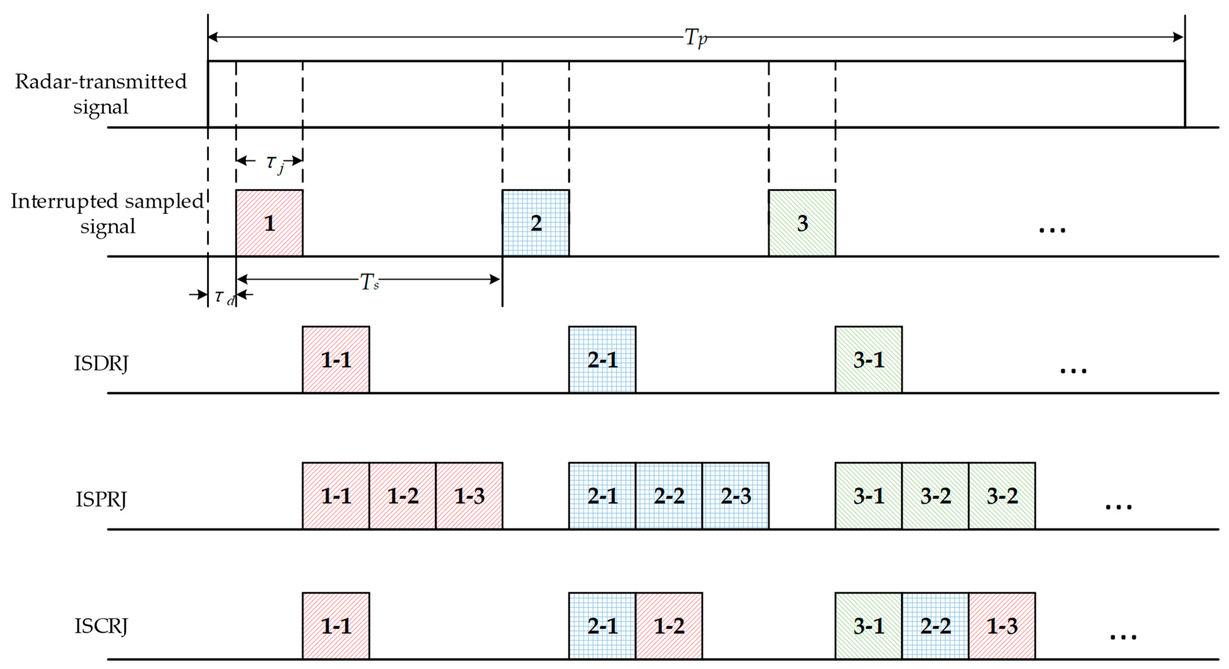
The schematic diagram of the time-frequency distribution of the intrapulse frequency-coded joint FM slope agile waveform designed in this article is shown in Figure 1.
In Figure 1, the pulse duration of the designed waveform is T p . The waveform has several subpulses, each of which has a duration of T s u b . Each subpulse is linear frequency modulated, but each subpulse has a different bandwidth and center frequency. The minimum bandwidth of the subpulse is B min , and the maximum bandwidth is B max . Moreover, the polarity of the FM slope of adjacent subpulses is agile. In engineering, waveform generators often need time to update parameters and reset logic when producing different waveforms. Therefore, we insert a delay slice between adjacent subpulses, and the duration of the delay slice is T d ( T d T s u b ) .
The number of subpulses contained in the transmitted signal is N = T p / ( T s u b + T d ) , and denotes rounding down. The bandwidth range of the subpulse is B min ~ B max . The bandwidth of the nth subpulse is B n = B min + ( a n 1 ) Δ B , and Δ B = ( B max B min ) / ( N 1 ) is the minimum interval of the subpulse bandwidth. a n { 1 , 2 , , N } is the subpulse bandwidth coding sequence, and when i j , a i a j . The neighboring subpulses are modulated with positive and negative FM slopes. The FM slope of the nth subpulse is k n = ( 1 ) n 1 B n / T s u b . The center frequency of the nth subpulse is f n = f 0 + ( b n 1 ) Δ f B 0 / 2 , where f 0 represents the initial carrier frequency of the subpulse, Δ f = B 0 / ( N 1 ) is the minimum interval of the subpulse carrier frequency, and B 0 is the maximum interval of the subpulse carrier frequency. The value of B 0 should be large to reduce the correlation of neighboring subpulses. b n { 1 , 2 , , N } is the subpulse frequency coding sequence, and when i j , b i b j .
The intrapulse frequency-coded joint FM slope agile waveform transmitted by the radar is
s t = n = 1 N s n t   = n = 1 N rect t 2 n 1 T s u b / 2 n 1 T d T s u b exp j 2 π f n t 2 n 1 T s u b / 2 n 1 T d + j π k n t 2 n 1 T s u b / 2 n 1 T d 2 ,
where s n t is the nth subpulse of the transmitted signal, and n = 1 , 2 , , N . rect u = 1 , u 1 / 2 0 , other is a rectangular window function.

2.2. ISRJ Model

According to different forwarding times and forwarding methods, ISRJ can be divided into three types [16]: interrupted-sampling direct repeater jamming (ISDRJ), interrupted-sampling periodic repeater jamming (ISPRJ), and interrupted-sampling cyclic repeater jamming (ISCRJ). The process of generating ISRJ by jammer is shown in Figure 2.
In Figure 2, the jammer first samples the radar signal intermittently. Box patterns with different colors and numbers indicate different sampled sections of the radar signal. τ j is the duration of the jammer sampling pulse, T s is the repetition period of the sampling pulse, and τ d is the jammer sampling delay. Then, the jammer forwards the sampled section. Box patterns with the same color but different numerical labels represent the same sampled section at different forwarding times. The jammer forwards the sampled section once to form ISDRJ and forwards the sampled section several times to form ISPRJ. ISCRJ is generated by forwarding current and past stored sampled sections.
The jammer sampling pulse train p t is a pulse train with a rectangular envelope, which is defined as follows [3]:
p t = rect t τ d τ j / 2 τ j i = 0 L 1 δ t i T s ,
where L is the number of sampling pulses, and represents the convolution operation.
Intermittent sampling of the radar-transmitted signal by jammer is equivalent to the product of the radar-transmitted signal and sampling pulse train, so the interrupted sampled signal can be expressed as
s s t = s t p t .
Then, the jammer can obtain three typical types of ISRJ by controlling the forwarding times and forwarding modes as follows [26]:
j I S D R J t = A j s s t τ j ,
j I S P R J t = A j m = 1 M s s t m τ j ,
j I S C R J t = A j r = 0 R 1 s s t τ j r τ j + T s ,
where j I S D R J t , j I S P R J t , and j I S C R J t stand for ISDRJ, ISPRJ, and ISCRJ, respectively. A j denotes the interference amplitude. M is the number of periodic forwarding times of ISPRJ, and M = T s / τ j 1 . R is the number of cyclic forwarding times of ISCRJ, and R = min M , L ,   L = T p / T s . min means to take the minimum value.

2.3. Echo Signal Model

Assume that there is a point target in the radar observation scenario, and the distance between the target and the radar is R 0 . The initial time delay of the target is t 0 = 2 R 0 / c , and the target echo signal is
s t a r t = A t s t t 0 ,
where A t represents the target amplitude.
Substituting s t into Equations (4)–(6), the specific expressions of the ISDRJ, ISPRJ, and ISCRJ can be obtained, respectively. To facilitate the analysis, the different ISRJs are uniformly expressed in terms of j I S R J t . Then, the ISRJ received by the victim radar can be expressed as j I S R J t t 0 .
The echo signal received by the radar is
s r t = A t s t t 0 + j I S R J t t 0 + n t ,
where n t denotes Gaussian white noise.

3. Dual-Parameter Agile Waveform Characteristics Analysis

Ref. [25] designed an intrapulse FM slope agile signal to make the FM slope of the target and interference different, and then suppress interference in the fractional domain. However, in terms of waveform design, the intrapulse single-parameter (i.e., FM slope) agile signal [25] has two disadvantages. On the one hand, the correlation of adjacent subpulses is strong, and the matched filter output of the intrapulse FM slope agile signal has high range sidelobes which easily cause range ambiguity, which is not conducive to target detection. On the other hand, the instantaneous change of the magnitude and polarity of the FM slope of adjacent subpulses is difficult to achieve in engineering, because the direct digital waveform synthesis requires time for logical reset and parameter update when forming different waveforms.
To overcome the two shortcomings above, this article designs an intrapulse frequency-coded joint FM slope agile waveform. The problem of difficult engineering implementation is solved by inserting a delay slice between adjacent subpulses. The range sidelobes of the transmitted signal are reduced by the dual-parameter (i.e., FM slope and center frequency) agility of the subpulses. Figure 3 compares the time-frequency distribution and PC output of the designed waveform with the waveform in [25]. Figure 4 simulates the ambiguity function diagram of the designed waveform.
The parameters of the following simulations are set as follows: T p = 100   μ s , T s u b = 5   μ s , subpulse bandwidth is 2~10 MHz, τ d = 0 , T d = T s u b , and the sampling frequency is 20 MHz. Subpulse bandwidth coding sequence a = [10,7,2,1,9,5,6,8,3,4]. Subpulse frequency coding sequence b = [4,9,1,8,2,7,3,6,5,10].
Figure 3a,b simulate the time-frequency distribution of the intrapulse single-parameter agile signal [25] and the intrapulse dual-parameter agile signal, respectively. It can be seen that the designed waveform in this article enhances the difference between subpulses and improves the mutual cover ability of subpulses through the center frequency and FM slope agility. Figure 3c compares the matched filter outputs of the two waveforms. The intrapulse dual-parameter agile waveform designed in this article has lower sidelobes than the intrapulse single-parameter agile waveform, and is therefore more conducive to target detection.
Figure 4 shows the ambiguity function diagram of the designed waveform, and the specific ambiguity function expression can be found in [27]. It can be seen from Figure 4a,b that the ambiguity function diagram of the designed waveform is approximately thumbtack type. In Figure 4c,d, both the zero-Doppler cut and zero-delay cut of the ambiguity function have narrow main lobes at the origin, indicating that the designed waveform has high range and velocity resolution.

4. ISRJ Suppression Method

The flow chart of the proposed interference suppression method is shown in Figure 5.
In Figure 5, the echo signal is first divided into several slices according to the subpulse timing of the transmitted signal. The inserted delay can be used as a trap to preliminarily filter the interference. Fractional order search and comparison are used to classify echo slices. Next, according to the approximate sparsity of target and interference in the fractional domain, the interference and target can be reconstructed by compressed sensing. Then, interference-free echo slices are extracted to construct a time-domain filter, and PC outputs after signal reconstruction are further filtered to reduce the range sidelobes. Finally, the echo signal after interference suppression is obtained.

4.1. Interfered Echo Slice Identification Based on FrFT

FrFT is a generalized Fourier transform with good focusing property for chirp signals. The principle of interfered echo slice classification is described below from the perspective of the energy-focusing property.
Assume that the chirp signal x t = r e c t t / T exp j π k t 2 with pulse duration T and FM slope k , then the FrFT of x t is as follows [28]:
X α u = K α t , u x t d t ,
where α = p π / 2 is the transform angle, p is the transform order, and K α t , u is the transform kernel function.
The expression of K α t , u [28] is
K α t , u = 1 j cot α exp j 2 π t 2 + u 2 2 cot α j 2 π u t csc α , i f   α   i s   n o t   a   m u l t i p l e   o f   π δ t u , i f   α   i s   a   m u l t i p l e   o f   2 π δ t + u , i f   α + π   i s   a   m u l t i p l e   o f   2 π .
When k + cot α = 0 , then α is the optimal transform angle and is denoted as α o p t . The transform order corresponding to the optimal transform angle is called the optimal transform order and is denoted as p o p t . The expression for the optimal transform angle is
α o p t = arc cot k .
Under α o p t , Equation (9) can be further expressed as
X α o p t u = K α t , u x t d t = 1 j cot α o p t e j π u 2 cot α o p t T sin π u csc α o p t T π u csc α o p t T .
Usually k ≫1, Equation (11) yields the approximate relations [12,25]: csc α o p t k and 1 j cot α o p t k . Substituting into Equation (12) and taking the absolute value yields
X α o p t u B T sin c π B u .
In (13), the output envelope of FrFT for x t is the sinc function, and its energy is mainly concentrated in the main lobe of the sinc function, which reflects the good energy-focusing property of FrFT for chirp signals.
In the context of the designed radar-transmitted waveform, the ISRJ and the target in the interfered echo slices have different FM slopes due to the time-domain discontinuity of the ISRJ. Assuming that the FM slopes of the interference and the target are k j and k t respectively, then under the corresponding optimal transform angle α o p t _ j = arc cot k j and α o p t _ t = arc cot k t , the FrFT outputs of the interference and target are
X α o p t _ t u A t B t T s l i c e sin c π B t u ,
X α o p t _ j u A j B j T s l i c e sin c π B j u ,
where B t and B j are the bandwidths of the target and interference, respectively, and T s l i c e is the length of the interfered echo slice.
Since the interference energy is usually much larger than the target, there is A j A t Therefore, X α o p t _ j u max X α o p t _ t u max . This indicates that the transform order corresponding to the maximum FrFT output of the interfered echo slice is the optimal transform order of the interference due to the energy suppression of the interference. When the echo slice contains only the target, the FrFT output of the slice is maximized at the optimal transform order of the target. According to these characteristics, the FrFT output of the echo slice can be first traversed over the fractional order to find the transform order when the FrFT output of the echo slice obtains the maximum value, and then compared with the optimal transform order of the corresponding subpulse of the transmitted signal. When the error is greater than the decision threshold, the echo slice is judged to be an interfered echo slice, and when the error is less than or equal to the decision threshold, the echo slice is judged to be an interference-free echo slice. The selection of the decision threshold is generally the step size of the order.

4.2. Interference Suppression Based on Signal Reconstruction Joint Time-Domain Filtering

The specific steps of the interference suppression method based on signal reconstruction joint time-domain filtering are as follows:
I.
Time-domain preliminary filtering. The echo signal is divided into several slices according to the width of the transmitted signal subpulse. According to the delay position inserted between the adjacent subpulses, the echo signal at the corresponding position is zeroed.
II.
Echo slice classification. Each remaining echo slice is classified to determine whether it is an interfered echo slice or an interference-free echo slice. The specific steps are as follows:
(a)
The set of echo slices to be classified is s r _ 1 ,   s r _ 2 ,     , s r _ N . Set the fractional order traversal range to 0~2 and the step size to Δ p . The FrFT of each echo slice is traversed to find the fractional order corresponding to the maximum FrFT output of the echo slice. The pseudo-code of the specific algorithm (Algorithm 1) is as follows:
Algorithm 1: Fractional Order Search
Input: echo slice set S , number of slices N , upper and lower bounds for order traversal D,
  step size Δ p
Output: optimal fractional order set of echo slices p s = p s _ 1 , p s _ 1 , , p s _ N .
Initialize: p s = ; D = ( 0 , 2 )
1:for (i =1 to N ) do
2:for (p = 0 to 2 with step size Δ p ) do
3:Compute the FrFT of s r _ i at order p according to Equation (9);
4:end for
5:Search for the maximum value of the FrFT of s r _ i in the traversal range;
6: p s _ i = arg max p max FrFT p s r _ i ; // FrFT p is the FrFT operator at order p
7:end for
8:return  p s = p s _ 1 , p s _ 1 , , p s _ N
(b)
The optimal transform orders of the subpulses in the radar-transmitted signal are known as the prior information. The optimal transform order set of the transmitted subpulses is denoted as p 0 = p 1 , p 2 ,   , p N . Comparing the optimal order set p s of the echo slice in step 2.1 with p 0 , the error of the ith slice is Δ i = p s _ i p i ,   i = 1 , 2 , , N . Set the threshold to Δ p . When Δ i Δ p , it is judged that the echo slice contains only the target, and when Δ i > Δ p , it is judged that the echo slice is jammed.
III.
Signal reconstruction. After step 2, we know the optimal transform orders of the interference and the target in interfered echo slices. According to the focusing property of FrFT for chirp signals, the FrFT outputs of the target and interference signal are approximately sparse under their respective optimal transform order. Therefore, the fractional sparse matrix can be constructed, and the target and interference can be reconstructed by the compressed sensing algorithm. The specific steps are as follows:
(a)
Target-jamming joint dictionary construction. We used the Pei-type discrete FrFT algorithm [29] to construct the sparse matrix. Take the sparse matrix construction of x t as an example.
First, we sample x t in the time domain and the fractional domain. Let the sampling intervals of x t in the time domain and fractional domain be Δ t and Δ u , and the resulting sampled signals are x w = x w Δ t , w [ W , W ] and θ p z = X p z Δ u , z [ Z , Z ] , respectively. Z and W are all integers. 2 W + 1 and 2 Z + 1 are sampling points in the time domain and fractional domain, respectively.
The discrete FrFT corresponding to Equation (9) can be expressed in terms of the matrix as
θ p = K p x ,
x = x W , x W + 1 , , x W T ,
θ p = θ p Z , θ p Z + 1 , , θ p Z T ,
where K p is the p-order discrete FrFT matrix.
The elements of K p are [30]
K p z , w = sgn sin α sin α j cos α 2 Z + 1 exp j z 2 Δ u 2 cot α 2 j 2 π S w z 2 Z + 1 + j w 2 Δ t 2 cot α 2 ,
where S is an integer that is prime to 2 Z + 1 .
Let S = sgn sin α = ± 1 , for sin α > 0 , Equation (19) can be further written as
K p z , w = sin α j cos α 2 Z + 1 exp j z 2 Δ u 2 cot α 2 2 π z w 2 Z + 1 + w 2 Δ t 2 cot α 2 .
The orthogonal base dictionary [30] is used in this article. Let W = Z , the p-order base dictionary of the fractional domain is
Ψ p = K p 1 = K p z , w H .
It is assumed that the ith echo slice is the interfered echo slice. It can be seen from step 2 that the optimal transform order of the interference in the ith echo slice is p s _ i and the optimal transform order of the target is p i . Therefore, the sparse matrices corresponding to the interference and target are Ψ p s _ i and Ψ p i , respectively. Then, the target-interference joint base dictionary is constructed as
Ψ t j = Ψ p i   Ψ p s _ i .
  • (b)
    Observation of interfered echo slice. The observation matrix Φ has Q rows and 2 W + 1 columns, and Q 2 W + 1 . Φ is an independent and identically distributed Gaussian random matrix. The observed signal vector obtained by measuring the ith echo slice is
l = Φ s r _ i = Φ Ψ t _ j θ t _ j + n = Φ Ψ t _ j θ t _ j + ε ,
where θ t _ j = θ t θ j is the target-jamming joint sparse vector, θ t is the target sparse vector, and θ j is the interference sparse vector. n is the noise, and ε = Φ n is the observation vector of the noise.
  • (c)
    The solution of θ t _ j can be converted to the following L 1 norm optimization problem, i.e.,
  θ ^ t _ j = arg min θ t _ j 1   s . t .   l Φ Ψ t _ j θ t _ j δ ,
where δ is a constant related to the noise.
The reconstructed target and interference in the ith slice are
  s ^ i = Ψ p i   θ ^ t ,
  j ^ i = Ψ p s _ i   θ ^ j .
IV.
Reconstruct the target and interference in each interfered echo slice. Subsequently, the echo signal after target reconstruction is obtained as s r t .
V.
Further time-domain filtering. The interference-free echo slices identified in step 2 are extracted and noted as s f r e e t . Convolve s f r e e t with the radar-transmitted signal, and a normalized time-domain filter [22] is constructed as
H t = s f r e e t s t max s f r e e t s t .
Convolving s r t with the radar-transmitted signal yields the PC output of the echo signal after target reconstruction, i.e.,
y r t = s r t s t
By passing y r t through H t , the PC output after further time-domain filtering is obtained as
y ˜ r t = y r t H t .

5. Simulation Result

In this section, simulation experiments are conducted to verify the effectiveness of the proposed method. It is worth noting that the intrapulse frequency-coded joint FM slope agile waveform requires the subpulse duration to be less than or equal to the jammer sampling pulse width to take advantage of proactive anti-jamming. In this article, it is assumed that the radar has already obtained the interference parameters during the environment sensing process, and the subpulse duration is less than or equal to the jammer sampling pulse width. At the same time, for the convenience of analysis, the simulation experiments first consider the case when the two are equal. The radar-transmitted waveform and interference parameters in the simulations are shown in Table 1.
The time-frequency distribution of the radar-transmitted waveform is shown in Figure 6.
In Figure 6, the transmitted waveform has ten subpulses, each of which has a different bandwidth and center frequency. The polarity of adjacent subpulses is agile, and delay slices are inserted between adjacent subpulses.

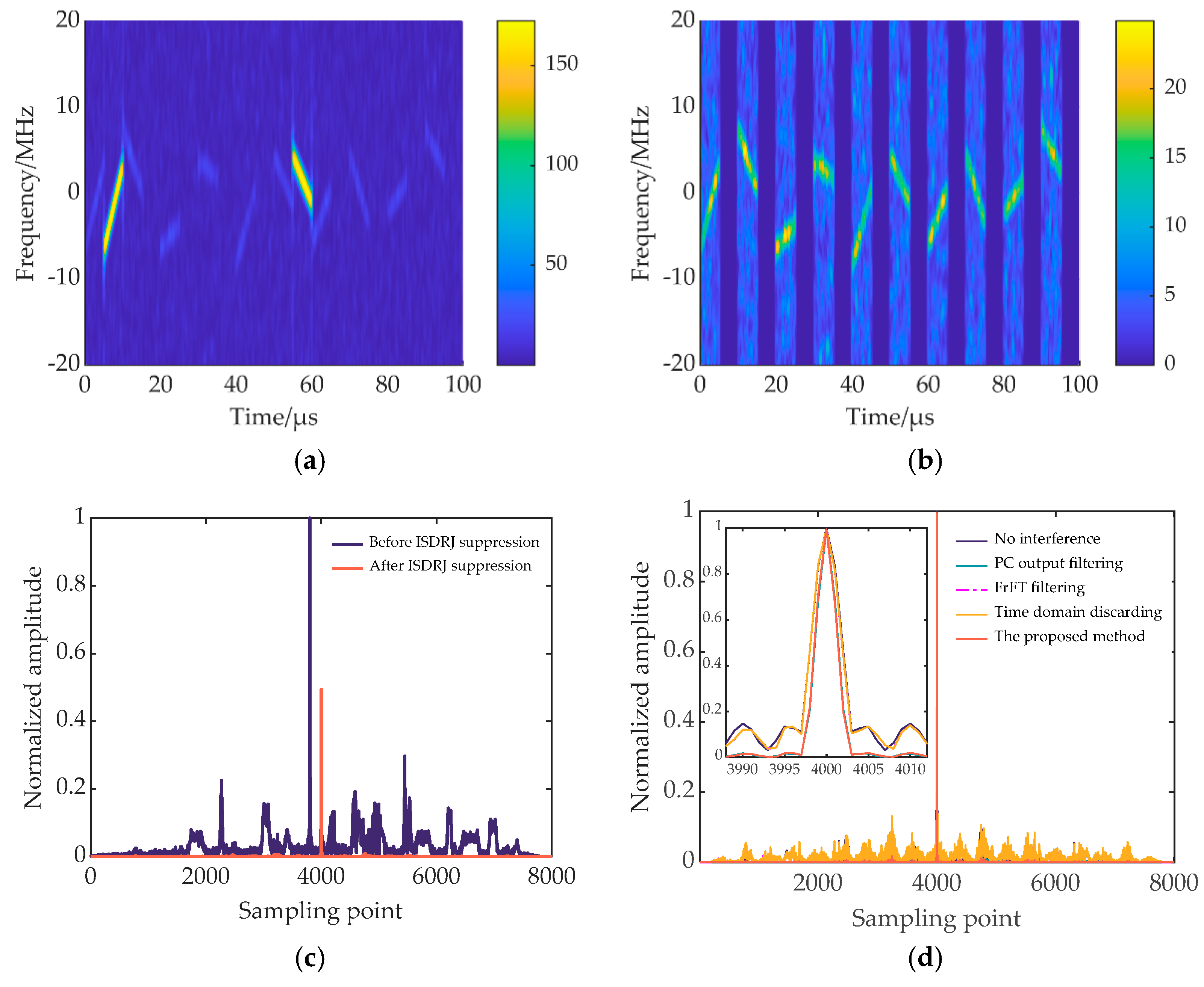
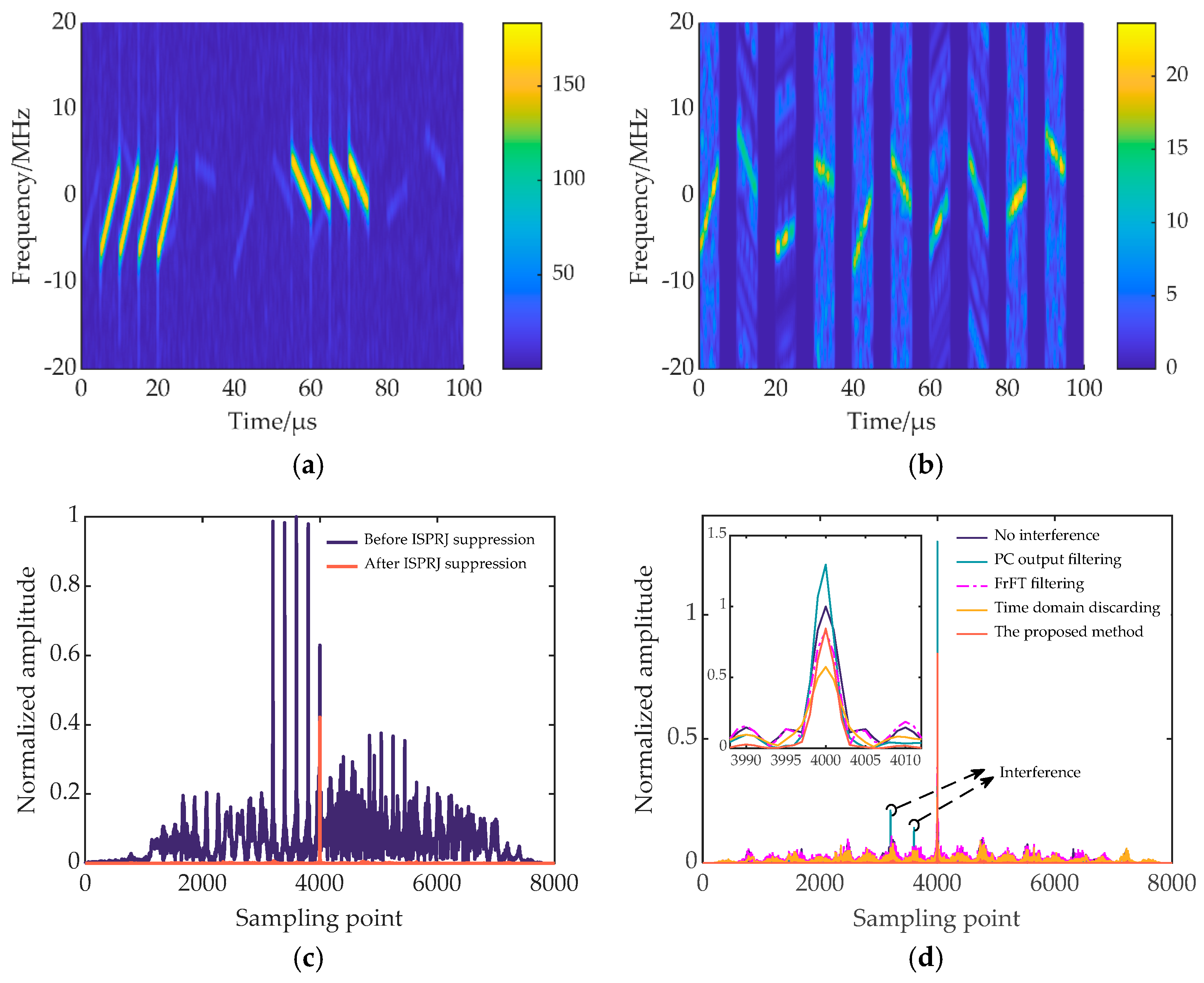
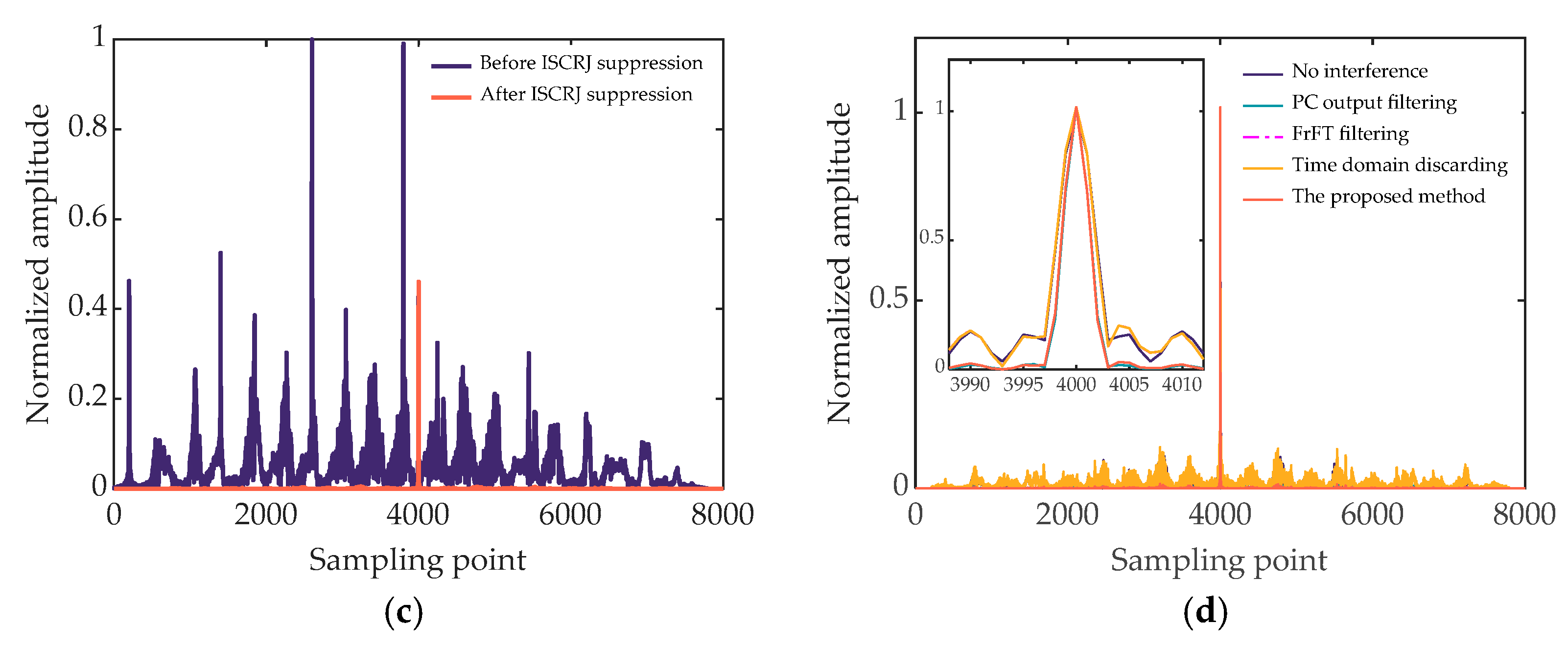
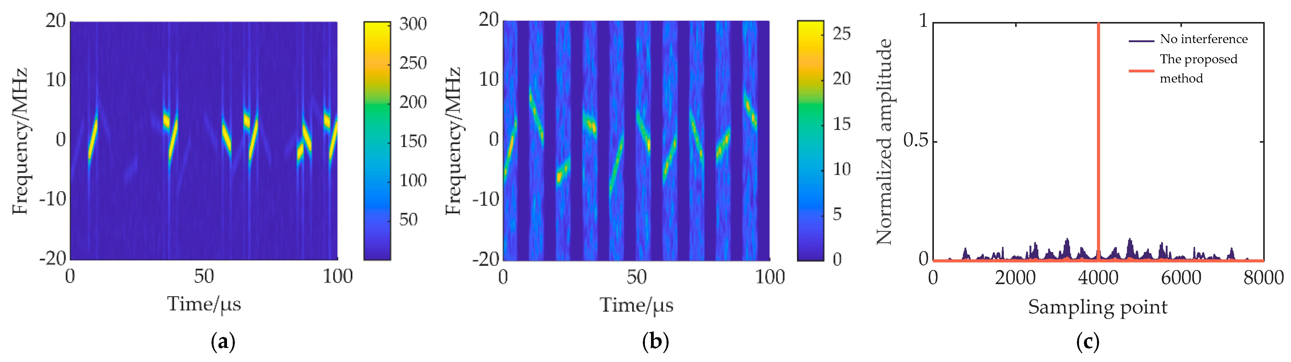
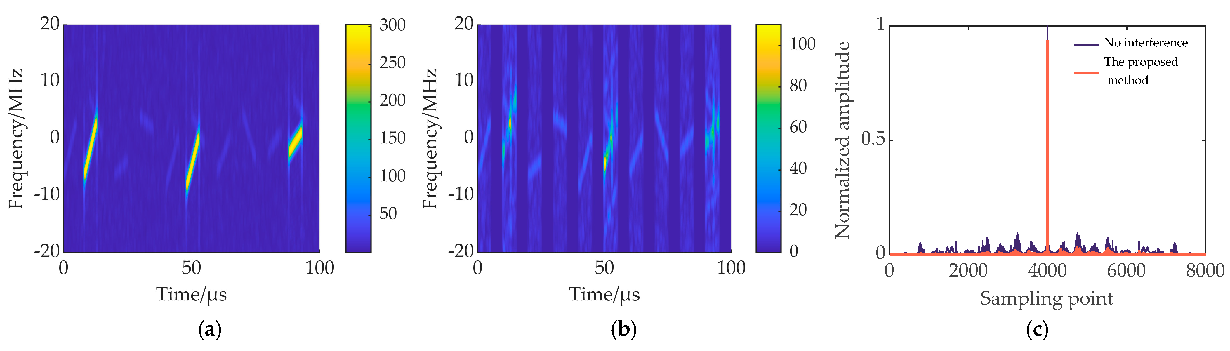
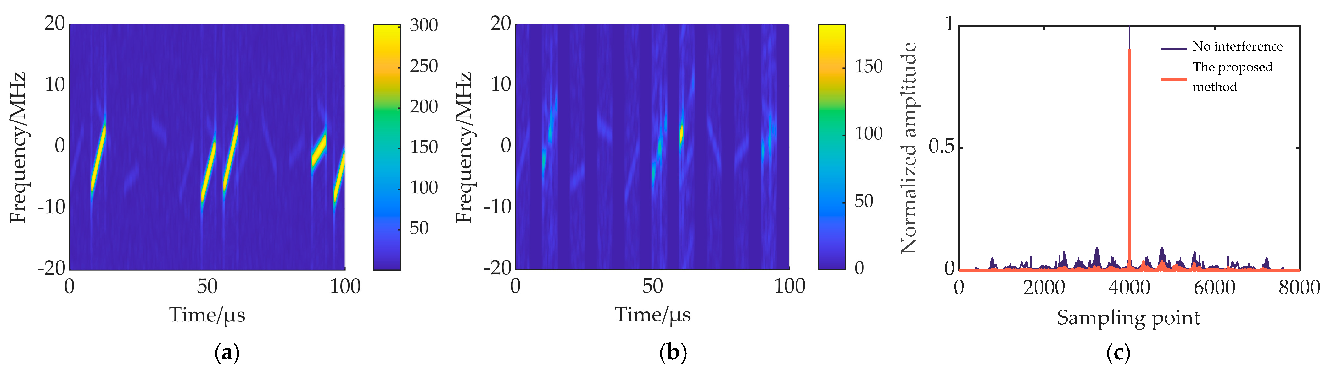
5.1. Interference Suppression Effect

It is assumed that the jammer samples the radar-transmitted signal synchronously, i.e., the sampling delay τ d = 0 . The interference suppression results for three typical types of ISRJ are shown in Figure 7, Figure 8, and Figure 9, respectively.
Figure 7a, Figure 8a, and Figure 9a show the time-frequency diagrams of the transmitted signal designed in this article under interference from the three types of ISRJ, respectively. It can be seen that the inserted delay slices between the subpulses have two specific effects when fighting against jamming. First, when the jammer intermittently samples, it protects part of the subpulses, so that the jammer cannot sample all subpulses. Second, when the jammer intermittently forwards, part of the interference falls in the delay slices and cannot interfere with the target signal. As shown in Figure 7a and Figure 9a, all the interference in the echo signal falls into the delay slices. Therefore, in the time-domain preliminary filtering, the delay slice can be zeroed to completely suppress the interference, and there is no target energy loss. In Figure 8a, some subpulses of the echo signal are interfered with by ISPRJ, so further interference suppression is required after time-domain preliminary filtering. Figure 7b, Figure 8b, and Figure 9b show the time-frequency diagrams of the echo signal after target reconstruction, where the targets in Figure 7b and Figure 9b are lossless, and the target in some of the slices in Figure 8b is the reconstructed target. The comparison shows that the target signal can be reconstructed efficiently in the fractional domain by compressed sensing. Then, after matched filtering and further time-domain filtering, the PC outputs of the echo signal before and after interference suppression are shown in Figure 7c, Figure 8c, and Figure 9c. It can be seen that the proposed method can effectively suppress the three typical ISRJs. Figure 7d, Figure 8d, and Figure 9d are the comparison results of PC output after ISRJ suppression by using PC output filtering [22], FrFT filtering [12], time domain discarding [13], and the proposed method under the transmitted signal designed in this paper. For the echo signal interfered with by ISDRJ or ISCRJ, the interference all falls in the delay slice, so there is no target energy loss in the PC outputs for different processing methods after time-domain preliminary filtering. However, the method in [22] and the proposed method have lower range sidelobes. When the echo signal is interfered with by ISPRJ, some subpulses are jammed. At this time, the method in [13] eliminates the identified interfered echo slices, resulting in a large target energy loss. Ref. [22] extracts interference-free slices through time-frequency analysis and constructs a time-domain filter to directly filter echo PC output, which preserves the signal energy in the target range cell. However, for strong false targets in other range cells, large peaks can still be formed after suppression and will affect radar detection. In [12], the interference spectrum peak is suppressed in the fractional domain. Although most of the interference is suppressed, the remaining interference will lead to higher range sidelobes. In contrast, the proposed method retains the target and suppresses the interference by signal reconstruction in the fractional domain. Then, a time-domain filter is constructed to further filter the PC output after target reconstruction, and the range sidelobes formed by the residual interference are reduced to a great extent. In summary, the proposed method is superior.

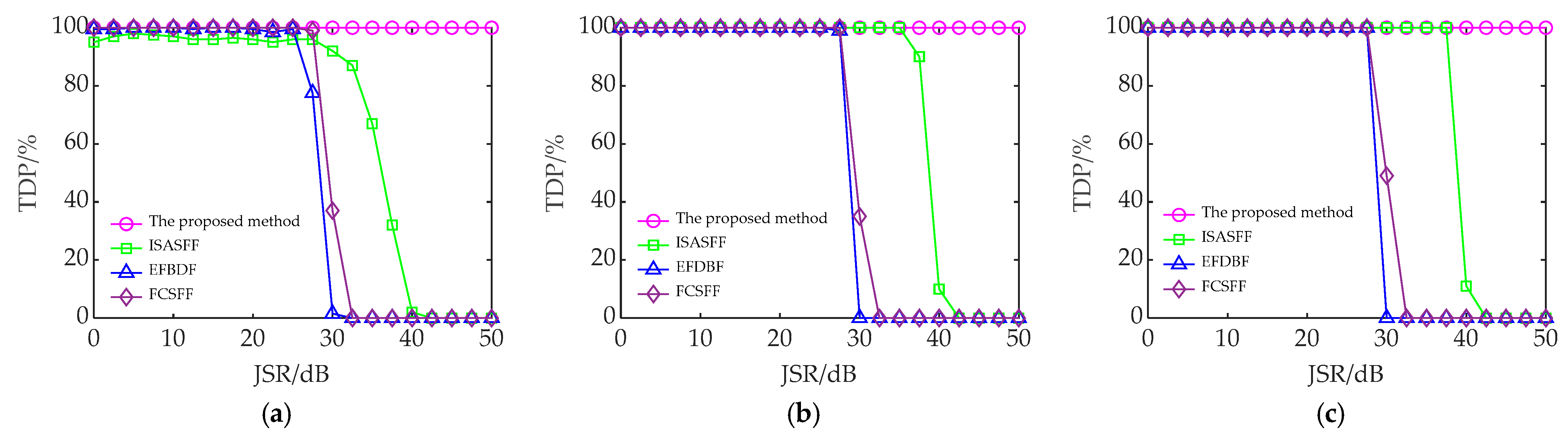
5.2. Performance Analysis of the Proposed Method

In this article, the signal reconstruction in the interfered echo slices and the construction of the time-domain filter both depend on the accurate classification of the echo slice. The classification accuracy (CA) of the interfered echo slices is used as the evaluation criterion. CA is the average ratio of the interfered echo slices being correctly classified, and its expression is as follows:
C A = 100 M C N i = 1 M C N j = 1 N t o t a l U i j N t o t a l ,
where M C N denotes the number of Monte Carlo experiments, N t o t a l is the actual number of interfered echo slices, and U i j represents the metric for classifying the jth interfered echo slice in the ith Monte Carlo experiment. When the jth interfered echo slice is classified correctly, the value is 1. Otherwise, the value is 0.
To investigate the CA of the proposed method on the interfered echo slices, the variation range of SNR is set to be −10~10 dB, the values of JSR are 5 dB, 10 dB, 15 dB, and 20 dB, respectively, and the number of Monte Carlo experiments is 200. The CA curves of the proposed slice order optimizing and comparison (SOOC) method and time-domain blanking (TDB) [24] method for the interfered echo slices are shown in Figure 10.
The TDB method classifies the echo slices by energy difference between the interfered and interference-free echo slices and has good classification performance at higher JSR. However, when SNR and JSR are low, the main component in the echo is noise. At this time, the amplitude of the noise overshadows the target and the interference, making it difficult for the TDB method to accurately classify the echo slices. In contrast, the proposed SOOC method utilizes the energy-focusing property of FrFT on chirp signals to improve the classification ability of echo slices at low SNR. As shown in Figure 10, under the same SNR and JSR conditions, the classification accuracy of the SOOC method is higher than that of the TDB method for the interfered echo slices, and the classification accuracy is more than 90% at low SNR, which shows good noise immunity performance.
We adopt target detection probability (TDP) [31] as the evaluation criterion for interference suppression performance, and TDP is defined as follows:
TDP = 100 M C N i = 1 M C N E i ,
where E i denotes the metric for the target detection in the ith Monte Carlo experiment. Searching for the peak value of the PC output of the echo signal after interference suppression, the value of E i is 1 if the peak coordinate is consistent with the target location, and 0 otherwise.
The number of Monte Carlo experiments is set to 200. The interference suppression of the echo signal is carried out by using the proposed method, the intrapulse slope agile signal joint fractional filtering (ISASFF) method [25], the energy function detection and band-pass filtering (EFDBF) method [11], and the frequency-coded signal joint fractional filtering (FCSFF) method [24], respectively. For different types of ISRJ, the TDP curves of different methods at different JSRs and SNRs after interference suppression are shown in Figure 11, Figure 12 and Figure 13.
In Figure 11, Figure 12 and Figure 13, the performance of all four methods improves to different degrees as the SNR increases. When JSR is small, the TDP of all four methods exceeds 90%. However, as the JSR increases, the performance of the four methods decreases to different degrees. At the same SNR and JSR, the TDP of the proposed method after interference suppression is greater than that of the other three methods. Furthermore, taking the critical value of JSR when TDP ≥ 90% as the index to measure the anti-jamming performance of different methods, the JSR tolerances of the four methods for different types of ISRJ at different SNRs are shown in Table 2.
In Table 2, as the SNR increases, the JSR tolerance of different methods also increases. Under the same conditions, the ISR tolerances of the proposed method are all higher than that of the other three methods. When JSR = 50 dB, the TDP of the proposed method after interference suppression is still ≥90%. In addition, compared with the other three methods, the proposed method is not affected by the interference type and can maintain a stable anti-interference performance under different types of ISRJ.

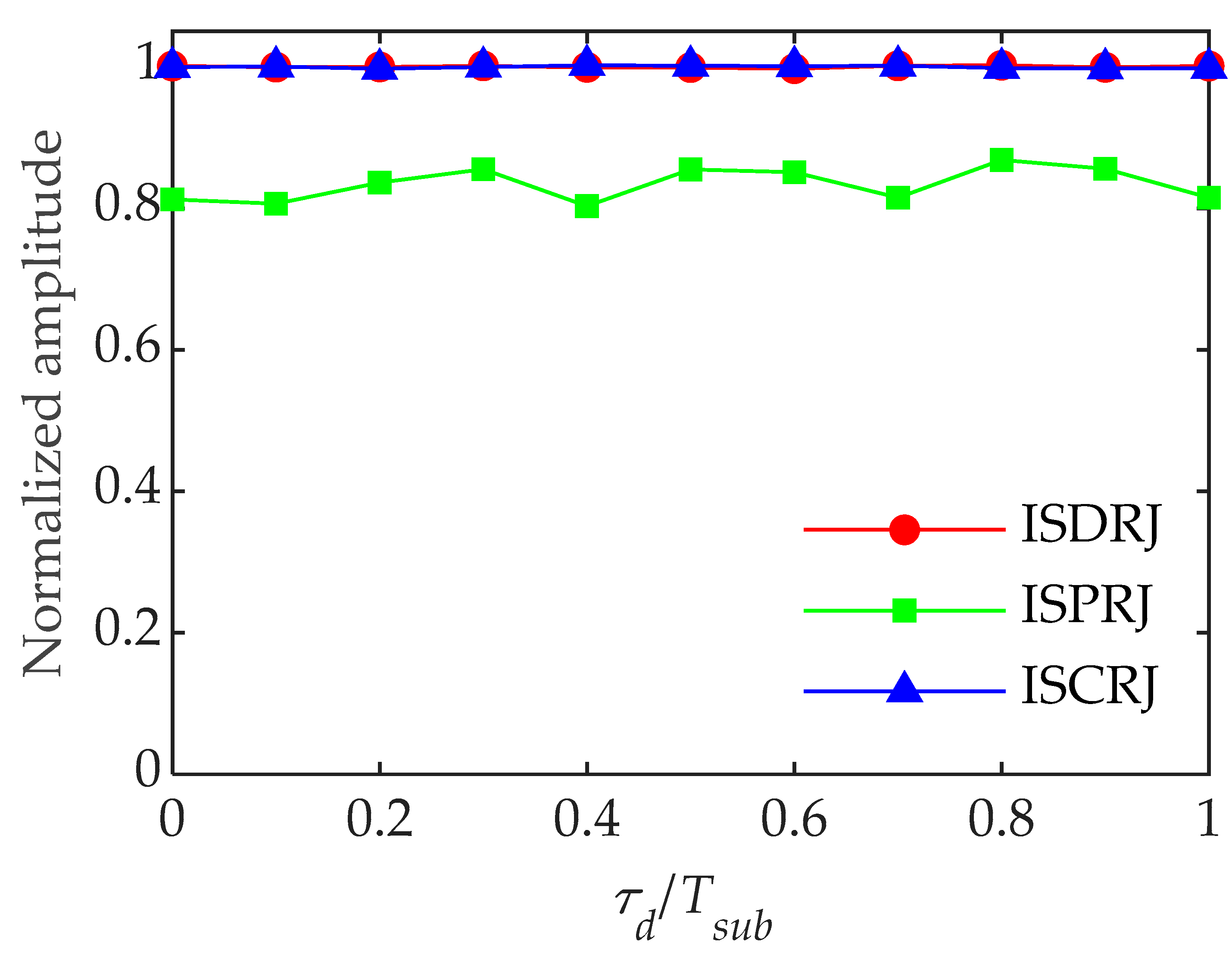
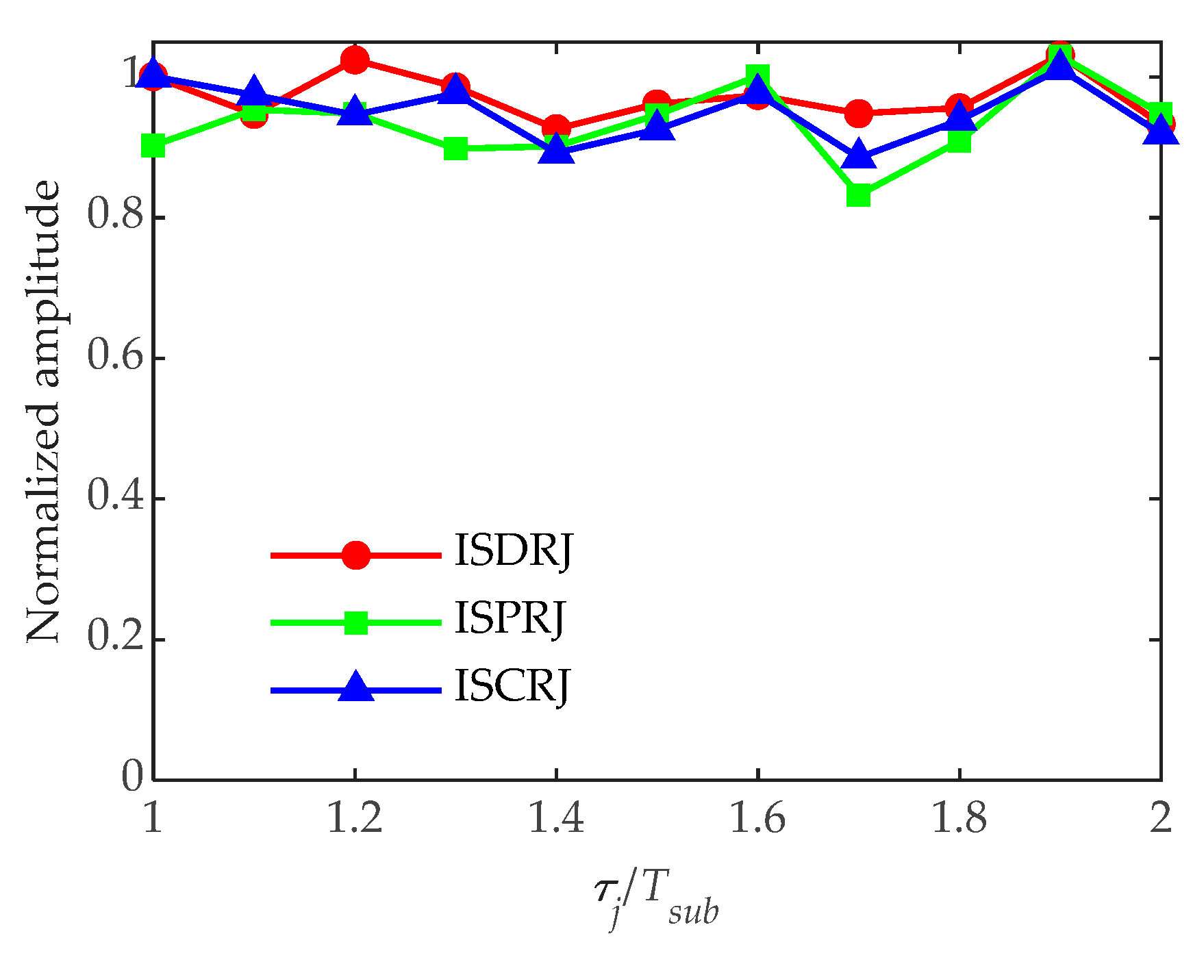
5.3. Influence of Jammer Sampling Delay

The above simulation experiments are all conducted under synchronous sampling of the jammer. In the following, we analyze the anti-interference performance when the jammer samples non-synchronously. Set the sampling delay to 2 μs, JSR = 25 dB, and SNR = 0 dB. The results of suppressing the three types of ISRJ by the proposed method are shown in Figure 14, Figure 15 and Figure 16.
In Figure 14a and Figure 16a, the interference slices of ISDRJ and ISCRJ all fall in the delay slices of the echo signal. The interference can be completely suppressed by the time-domain preliminary filtering, and the target signal is well preserved as shown in Figure 14b and Figure 16b. Therefore, there is no target energy loss in PC outputs in Figure 14c and Figure 16c. In Figure 15a, the jammer sampling delay increases the number of interfered echo slices and makes it more difficult to suppress the interference. In Figure 15b, after signal reconstruction and interference cancellation, most of the interference is eliminated, but some residual interference still exists and will generate high range sidelobes. To degrade the range sidelobes, further time-domain filtering is conducted. Figure 15c shows the range profile of the target after further time-domain filtering. It can be seen that the range sidelobe is reduced to a great extent, and the target has some energy loss because of the error of the reconstruction.
The value of τ d / T s u b is taken from 0 to 1, the number of Monte Carlo experiments is 200, and other parameters are unchanged. Figure 17 shows the target normalized amplitude after interference suppression versus τ d / T s u b .
In Figure 17, for ISDRJ and ISCRJ, the target normalized amplitude after interference suppression is approximately 1. This is because the interference slices all fall in the delay slices, and no interfered echo slices exist. Therefore, there is almost no target energy loss after interference suppression. For ISPRJ, the sampling delay increases the number of interfered echo slices in the echo signal. Then, due to the existence of noise, the signal reconstruction in the disturbed echo slice will inevitably have errors, which leads to target energy loss. Overall, the normalized amplitude of the target after interference suppression does not fluctuate much with the increase of τ d / T s u b , which indicates that the proposed method is not sensitive to the sampling delay of the jammer.

5.4. Influence of Jammer Sampling Pulse Width

The above experiments are carried out under the special case that the sampling pulse width of the jammer is equal to the subpulse width. The following simulation analyzes the situation where the jammer sampling pulse width is larger than the subpulse width. Set τ j / T s u b = 1.6 , JSR = 25 dB, SNR = 0 dB and τd = 0. The anti-interference results of the proposed method are as follows.
Comparing Figure 18a, Figure 19a, and Figure 20a with Figure 7a, Figure 8a, and Figure 9a, respectively, the number of interfered echo slices increases when τ j > T s u b . In Figure 18b, Figure 19b, and Figure 20b, the interference in some interfered echo slices is not well reconstructed and canceled, because in some slices, the interference signal does not completely fill the entire slice length, causing difficulty in subsequent reconstruction. This residual interference will lead to high range sidelobes after PC, but further time domain filtering can reduce it. In Figure 18c and Figure 20c, the target has some energy loss due to reconstruction errors. However, in Figure 19c, the peak value of the target exceeds 1, because there is more residual interference in the echo signal interfered with by ISPRJ, and the PC output of the residual interference enhances the energy of the target range unit. In summary, although the increase in jammer sampling pulse width makes signal construction difficult, further time domain filtering can degrade its impact.
The value of τ j / T s u b is further set as 1~2, other parameters remain unchanged, and the number of Monte Carlo experiments is 200. The target normalized amplitude after interference suppression versus τ j / T s u b is shown in Figure 21.
In Figure 21, the target normalized amplitude curves after suppression for three kinds of IDRJ exhibit great fluctuation with the change of sampling pulse width. There are two main reasons for this. One is that there is an error in signal reconstruction, which causes a loss of target energy during interference suppression. The second is that some residual interference exists after interference cancellation, and the PC output of the residual interference enhances the energy of the range unit where the target is located. Combining the two factors, the amplitude curve of the target greatly fluctuates.

6. Conclusions

For self-defense ISRJ, an anti-jamming method based on intrapulse dual parameter agile waveform is proposed in this paper. Compared with intrapulse frequency modulation slope agile waveform, this paper introduces subpulse center frequency agility and inserts delay slices between adjacent subpulses, which reduces the range sidelobes of the transmitted waveform autocorrelation and the difficulty of engineering implementation. The ambiguity function diagram of the designed waveform is approximated as a thumbtack type with good range and velocity resolution. The echo slice classification utilizes the energy-focusing property of FrFT for chirp signals and achieves a more robust performance. The echo signal data are fully utilized for interference suppression, in which signal reconstruction in the fractional domain is performed for the interfered echo slices to preserve the target energy, and a time-domain narrowband filter is constructed from the interference-free echo slices to reduce the effect of range sidelobes caused by the residual interference. The TDP of the proposed method is ≥ 90% when JSR = 50 dB, which effectively improves the radar’s anti-interference capability.
However, the designed signal has some disadvantages. The intrapulse agile waveform increases the complexity of the radar system, and the delay slice inserted in the transmitted signal sacrifices the detection range of the radar. The proposed method also has some limitations. Fractional order search is more computationally intensive and the complexity of the algorithm is relatively high. Then, the segmentation of echo slices requires an accurate estimation of the front edge of the echo signal, which is difficult to estimate at low SNRs. In addition, the performance of the proposed method is significantly degraded when multiple time-dislocated compound interferences or strong noise interferences are included. All of these need to be further studied in future work.

Author Contributions

Conceptualization, X.W. and B.L.; methodology, X.W.; validation, B.L.; software, X.W. and B.L.; investigation, X.W. and H.C.; formal analysis, B.L. and X.W.; resources, L.N. and Y.Z.; data curation, J.L. and Y.Z.; writing—original draft, X.W.; visualization W.L.; writing—review and editing, W.L.; supervision, H.C. and B.L. All authors have read and agreed to the published version of the manuscript.

Funding

This research was funded by the National Nature Science Foundation of China, grant numbers 62001510 and 62101593.

Data Availability Statement

The data presented in this study are available on request from the corresponding author.

Conflicts of Interest

The authors declare no conflicts of interest.

References

  1. Riabukha, V.P.; Semeniaka, A.V.; Katiushyn, Y.A.; Atamanskiy, D.V. Pulse DRFM Jamming Formation and Its Mathematical Simulation. In Proceedings of the 2022 IEEE 2nd Ukrainian Microwave Week (UkrMW), Kharkiv, Ukraine, 14–18 November 2022; pp. 654–659. [Google Scholar]
  2. Hanbali, S.B.S.; Kastantin, R. A review of self-protection deceptive jamming against chirp radars. Int. J. Microw. Wirel. Technol. 2017, 9, 1853–1861. [Google Scholar] [CrossRef]
  3. Wang, X.; Liu, J.; Zhang, W.; Fu, Q.; Liu, Z.; Xie, X. Mathematic principles of interrupted-sampling repeater jamming (ISRJ). Sci. China Ser. F Inf. Sci. 2007, 50, 113–123. [Google Scholar] [CrossRef]
  4. Lan, L.; Marino, A.; Aubry, A.; Maio, A.D.; Liao, G.; Xu, J.; Zhang, Y. GLRT-Based Adaptive Target Detection in FDA-MIMO Radar. IEEE Trans. Aerosp. Electron. Syst. 2021, 57, 597–613. [Google Scholar] [CrossRef]
  5. Lan, L.; Xu, J.; Liao, G.; Zhang, Y.; Fioranelli, F.; So, H.C. Suppression of Mainbeam Deceptive Jammer With FDA-MIMO Radar. IEEE Trans. Veh. Technol. 2020, 69, 11584–11598. [Google Scholar] [CrossRef]
  6. Wang, X.; Chen, H.; Ni, M.; Ni, L.; Li, B. Radar anti-false target jamming method based on phase modulation. Syst. Eng. Electron. 2021, 43, 2476–2483. [Google Scholar]
  7. Wang, X.; Chen, H.; Ni, L.; Ni, M.; Shen, W.; Zhang, J. False target suppression method based on stepped frequency and Doppler filtering. In Proceedings of the ICFEICT 2021: International Conference on Frontiers of Electronics, Information and Computation Technologies, Changsha, China, 21–23 May 2021; pp. 1–5. [Google Scholar]
  8. Yuan, H.; Wang, C.; Li, X.; An, L. A Method against Interrupted-Sampling Repeater Jamming Based on Energy Function Detection and Band-Pass Filtering. Int. J. Antennas Propag. 2017, 2017, 6759169. [Google Scholar] [CrossRef]
  9. Chen, J.; Wu, W.; Xu, S.; Chen, Z.; Zou, J. Band pass filter design against interrupted-sampling repeater jamming based on time-frequency analysis. IET Radar Sonar Navig. 2019, 13, 1646–1654. [Google Scholar] [CrossRef]
  10. Wang, Z.; Li, J.; Yu, W.; Luo, Y.; Zhao, Y.; Yu, Z. Energy function-guided histogram analysis for interrupted sampling repeater jamming suppression. Electron. Lett. 2023, 59, e12778. [Google Scholar] [CrossRef]
  11. Yang, S.; Tian, B.; Zhou, R. ECCM against Interrupted Sampling Repeater Jamming based on Time-frequency Analysis. J. Signal Process. 2016, 32, 1244–1251. [Google Scholar] [CrossRef]
  12. Wan, P.; Bai, W.; Fu, X. Fractional Fourier Transform-based LFM Radars for Countering Interrupted-sampling Repeater Jamming. Fire Control Command Control 2018, 43, 35–39. [Google Scholar]
  13. Zhang, J.; Mu, H.; Wen, S.; Li, Y.; Gao, H. Anti-Intermittent Sampling Repeater Jamming Method Based on LFM Segmented Pulse Compression. J. Electron. Inf. Technol. 2019, 41, 1712–1720. [Google Scholar] [CrossRef]
  14. Zhou, C.; Liu, Q.; Chen, X. Parameter estimation and suppression for DRFM-based interrupted sampling repeater jammer. IET Radar Sonar Navig. 2018, 12, 56–63. [Google Scholar] [CrossRef]
  15. Zhou, C.; Liu, Q.; Hu, C. Time-frequency analysis techniques for recognition and suppression of interrupted sampling repeater jamming. J. Radars 2019, 8, 100–106. [Google Scholar] [CrossRef]
  16. Lu, L.; Gao, M. An Improved Sliding Matched Filter Method for Interrupted Sampling Repeater Jamming Suppression Based on Jamming Reconstruction. IEEE Sens. J. 2022, 22, 9675–9684. [Google Scholar] [CrossRef]
  17. Zhou, K.; He, F.; Su, Y. Fast algorithm for joint waveform and filter design against interrupted sampling repeater jamming. J. Radars 2022, 11, 264–277. [Google Scholar] [CrossRef]
  18. Zhou, K.; Li, D.; Su, Y.; Liu, T. Joint Design of Transmit Waveform and Mismatch Filter in the Presence of Interrupted Sampling Repeater Jamming. IEEE Signal Process. Lett. 2020, 27, 1610–1614. [Google Scholar] [CrossRef]
  19. Wang, F.; Li, N.; Pang, C.; Li, C.; Li, Y.; Wang, X. Complementary Sequences and Receiving Filters Design for Suppressing Interrupted Sampling Repeater Jamming. IEEE Geosci. Remote Sens. Lett. 2022, 19, 4022305. [Google Scholar] [CrossRef]
  20. Yu, T.; Zhou, Z.; Du, X.; Bao, Q.; He, Y. An Anti-Interrupted Sampling Repeater Jamming Method Based on Complete Complementary Code Waveform Design. J. Electron. Inf. Technol. 2023, 45, 3896–3905. [Google Scholar] [CrossRef]
  21. Zhang, J.; Mu, H.; Wen, S.; Li, Y. Anti interrupted-sampling repeater jamming method based on stepped LFM waveform. Syst. Eng. Electron. 2019, 41, 1013–1020. [Google Scholar] [CrossRef]
  22. Du, S.; Liu, Z.; Wu, Y.; Sha, M.; Quan, Y. Frequency agility waveform combined with time-frequency filter to suppress interrupted-sampling repeater jamming. Syst. Eng. Electron. 2023, 45, 3819–3827. [Google Scholar] [CrossRef]
  23. Dong, S.; Wu, Y.; Fang, W.; Quan, Y. Anti-interrupted sampling repeater jamming method based on frequency-agile radar joint fuzzy C-means. J. Radars 2022, 11, 289–300. [Google Scholar] [CrossRef]
  24. Liu, Z.; Du, S.; Wu, Y.; Sha, M.; Xing, M.; Quan, Y. Anti-interrupted sampling repeater jamming method for interpulse and intrapulse frequency-agile radar. J. Radars 2022, 11, 301–312. [Google Scholar] [CrossRef]
  25. Wang, X.; Li, B.; Liu, W.; Chen, H.; Zhu, Y.; Ni, M. Anti-interrupted Sampling Repeater Jamming Based on Intra-pulse Frequency Modulation Slope Agile Radar Waveform Joint FrFT. Digit. Signal Process. 2024, 147, 104418. [Google Scholar] [CrossRef]
  26. Zhang, L.; Wang, G.; Zhang, X.; Li, S.; Xin, T. Interrupted-sampling repeater jamming adaptive suppression algorithm based on fractional dictionary. Syst. Eng. Electron. 2020, 42, 1439–1448. [Google Scholar] [CrossRef]
  27. Nadav, L.; Eli, M. Ambiguity Function. In Radar Signals; IEEE: New York, NY, USA, 2004; pp. 34–52. [Google Scholar]
  28. Almeida, L.B. The fractional Fourier transform and time-frequency representations. IEEE Trans. Signal Process. 1994, 42, 3084–3091. [Google Scholar] [CrossRef]
  29. Ozaktas, H.M.; Arikan, O.; Kutay, M.A.; Bozdagt, G. Digital computation of the fractional Fourier transform. IEEE Trans. Signal Process. 1996, 44, 2141–2150. [Google Scholar] [CrossRef]
  30. Fang, B.; Huang, G.; Gao, J.; Zuo, W. Compressive sensing of linear frequency modulated echo signals in fractional Fourier domains. J. Xidian Univ. 2015, 42, 200–206. [Google Scholar] [CrossRef]
  31. Wang, X.; Chen, H.; Liu, W.; Zhang, L.; Li, B.; Ni, M. Echo Preprocessing-Based Smeared Spectrum Interference Suppression. Electronics 2023, 12, 3690. [Google Scholar] [CrossRef]
Figure 1. Schematic diagram of the time-frequency distribution of the designed signal.
Remotesensing 16 02810 g001
Figure 2. Mechanism of ISRJ.
Remotesensing 16 02810 g002
Figure 3. Comparison of different radar-transmitted waveforms. (a) Time-frequency distribution of the intrapulse single-parameter agile waveform; (b) time-frequency distribution of the intrapulse dual-parameter agile waveform; (c) comparison of matched filter outputs of intrapulse single-parameter agile waveform and intrapulse dual-parameter agile waveform.
Remotesensing 16 02810 g003
Figure 4. Ambiguity function diagram of the intrapulse frequency-coded joint FM slope agile waveform. (a) Ambiguity function; (b) contour of ambiguity function; (c) zero-Doppler cut of the ambiguity function; (d) zero-delay cut of the ambiguity function.
Remotesensing 16 02810 g004
Figure 5. Flow chart of the proposed method.
Remotesensing 16 02810 g005
Figure 6. Time-frequency distribution of the radar-transmitted signal.
Remotesensing 16 02810 g006
Figure 7. ISDRJ suppression results. (a) Time-frequency diagram of the echo signal; (b) time-frequency diagram of the echo signal after target reconstruction; (c) PC results of the proposed method before and after interference suppression; (d) comparison of PC results of different processing methods.
Remotesensing 16 02810 g007
Figure 8. ISPRJ suppression results. (a) Time-frequency diagram of the echo signal; (b) time-frequency diagram of the echo signal after target reconstruction; (c) PC results of the proposed method before and after interference suppression; (d) comparison of PC results of different processing methods.
Remotesensing 16 02810 g008
Figure 9. ISCRJ suppression results. (a) Time-frequency diagram of the echo signal; (b) time-frequency diagram of the echo signal after target reconstruction; (c) PC results of the proposed method before and after interference suppression; (d) comparison of PC results of different processing methods.
Remotesensing 16 02810 g009aRemotesensing 16 02810 g009b
Figure 10. CA of the SOOC method and TDB method [24] for the interfered echo slices at different JSRs and SNRs. (a) The echo signal interfered with by ISDRJ; (b) the echo signal interfered with by ISPRJ; (c) the echo signal interfered with by ISCRJ.
Remotesensing 16 02810 g010
Figure 11. The TDP of the echo signal interfered with by ISDRJ after interference suppression. (a) SNR = −10 dB; (b) SNR = −5 dB; (c) SNR = 0 dB.
Remotesensing 16 02810 g011
Figure 12. The TDP of the echo signal interfered with by ISPRJ after interference suppression. (a) SNR = −10 dB; (b) SNR = −5 dB; (c) SNR = 0 dB.
Remotesensing 16 02810 g012
Figure 13. The TDP of the echo signal interfered with by ISCRJ after interference suppression. (a) SNR = −10 dB; (b) SNR = −5 dB; (c) SNR = 0 dB.
Remotesensing 16 02810 g013
Figure 14. ISDRJ suppression results (τd = 2 μs). (a) Time-frequency diagram of echo signal; (b) time-frequency diagram of echo signal after signal reconstruction; (c) PC results of the proposed method after interference suppression.
Remotesensing 16 02810 g014
Figure 15. ISPRJ suppression results (τd = 2 μs). (a) Time-frequency diagram of echo signal; (b) time-frequency diagram of echo signal after signal reconstruction; (c) PC results of the proposed method after interference suppression.
Remotesensing 16 02810 g015
Figure 16. ISCRJ suppression results (τd = 2 μs). (a) Time-frequency diagram of echo signal; (b) time-frequency diagram of echo signal after signal reconstruction; (c) PC results of the proposed method after interference suppression.
Remotesensing 16 02810 g016
Figure 17. Target normalized amplitude after interference suppression versus τ d / T s u b .
Remotesensing 16 02810 g017
Figure 18. ISDRJ suppression results (τj/Tsub = 1.6). (a) Time-frequency diagram of echo signal; (b) time-frequency diagram of echo signal after signal reconstruction; (c) PC results of the proposed method after interference suppression.
Remotesensing 16 02810 g018
Figure 19. ISPRJ suppression results (τj/Tsub = 1.6). (a) Time-frequency diagram of echo signal; (b) time-frequency diagram of echo signal after signal reconstruction; (c) PC results of the proposed method after interference suppression.
Remotesensing 16 02810 g019
Figure 20. ISCRJ suppression results (τj/Tsub = 1.6). (a) Time-frequency diagram of echo signal; (b) time-frequency diagram of echo signal after signal reconstruction; (c) PC results of the proposed method after interference suppression.
Remotesensing 16 02810 g020
Figure 21. Target normalized amplitude after interference suppression versus τ j / T s u b .
Remotesensing 16 02810 g021
Table 1. Parameter settings for simulation experiments.
ParameterSymbolValue
Radar-transmitted waveform duration T p 100 μs
Subpulse duration T s u b 5 μs
Inserted delay duration T d 5 μs
The number of subpulses N 10
Minimum bandwidth of subpulse B min 2 MHz
Maximum bandwidth of subpulse B max 10 MHz
Maximum carrier frequency interval of subpulse B 0 10 MHz
Sampling frequency f s 40 MHz
Jammer sampling pulse width τ j 5 μs
Interrupted-sampling repetition period T s 25 μs
Subpulse bandwidth coding sequencea[10,7,2,1,9,5,6,8,3,4]
Subpulse frequency coding sequenceb[4,9,1,8,2,7,3,6,5,10]
Jamming-to-signal ratioJSR20 dB
Signal-to-noise ratioSNR0 dB
Table 2. The JSR tolerance of different methods at different SNRs (dB).
TypeISDRJISPRJISCRJ
 SNR −10 dB−5 dB0 dB−10 dB−5 dB0 dB−10 dB−5 dB0 dB
Method  
Intrapulse slope agile signal joint fractional filtering (ISASFF)303537.527.53032.527.53030
Energy function detection and band-pass filtering (EFDBF)2527.527.522.522.522.5252527.5
Frequency-coded signal joint fractional filtering (FCSFF)27.527.527.527.527.527.527.53030
The proposed method505050505050505050
Disclaimer/Publisher’s Note: The statements, opinions and data contained in all publications are solely those of the individual author(s) and contributor(s) and not of MDPI and/or the editor(s). MDPI and/or the editor(s) disclaim responsibility for any injury to people or property resulting from any ideas, methods, instructions or products referred to in the content.

