Article

Real-Time Detection and Correction of Abnormal Errors in GNSS Observations on Smartphones

1
School of Transportation, Southeast University, Nanjing 211189, China
2
Research Group of Astronomy and Geomatics (gAGE), Universitat Politecnica de Catalunya (UPC), 08034 Barcelona, Spain
*
Author to whom correspondence should be addressed.
Remote Sens. 2024, 16(17), 3117; https://doi.org/10.3390/rs16173117
Submission received: 24 July 2024 / Revised: 15 August 2024 / Accepted: 21 August 2024 / Published: 23 August 2024

Abstract

:
Smartphones, due to the integration of low-cost GNSS chips and linearly polarized antennas, frequently experience abnormal errors in their observations, particularly during positioning on water surfaces. In response to this issue, this paper proposes a method for detecting and correcting abnormal errors in GNSS observations on smartphones. Firstly, the state and observation equations of the Kalman filter are formulated based on the continuous and smooth characteristics of pseudorange and carrier observations. Secondly, real-time detection of abnormal error occurrence in observations is performed by assessing whether the difference between the predicted and observed values computed by the Kalman filter exceeds a specified threshold. Finally, depending on abnormal errors within the epoch, different strategies are applied for real-time reparation of observations containing anomalies. Two smartphones have been used for static tests on land and kinematic tests on water. Results show that under various environmental conditions, the proposed method effectively enhances the quality of observations on smartphones. Specifically, the method achieved a maximum improvement of 86.03% in pseudorange quality and 84.31% in carrier phase quality. The method proposed in this paper outperformed the State-Based method by approximately 10% on land and by 10–35% on water. It also shows high stability and reliability, particularly in complex environments such as navigation on water.

1. Introduction

In recent years, smartphones have become ubiquitous in people’s lives. As navigation and positioning technologies in smartphones continue to advance, their potential for achieving higher accuracy in navigation and positioning has become increasingly promising [1,2,3,4,5,6,7,8]. Leveraging advantages such as low cost, high precision, and portability, smartphones have wide-ranging applications in areas such as smart driving, maritime positioning, and emergency rescue [9]. However, the use of low-cost GNSS chips and linearly polarized antennas in smartphones leads to poor quality observations, making them prone to frequent abnormal errors [10]. These abnormal errors significantly affect the quality of smartphone GNSS observations, making it difficult to meet the demands of high-precision positioning [11,12].
Currently, to mitigate the impact of abnormal errors and enhance the quality of smartphone observations, some scholars have conducted a series of studies focusing on three aspects: hardware devices, environmental conditions, and positioning algorithms. Regarding smartphone hardware specifically, prior research has demonstrated that the GNSS observation data from smartphones has serious quality issues and is significantly different from that of geodetic receivers, mainly in signal strength, measurement noise, and resistance to multipath effects [13,14].
Pesyna et al. [15] analyzed smartphone GNSS observations, emphasizing that the performance gap between smartphones and geodetic receivers is primarily due to the poorer multipath suppression capability of smartphone antennas compared to measurement-grade antennas. Geng et al. [16] analyzed the impact of smartphone antennas on observations. The results showed that the signal-to-noise ratio of smartphones is about 10 Db-Hz lower than that of geodetic receivers equipped with measurement-grade GNSS antennas. They believed that the linearly polarized smartphone antenna caused its observation data to be seriously affected by multipath effects. Kirkko-Jaakkola et al. [17] analyzed the observation quality of Nokia Lumia 1520 smartphones and U-Blox low-cost receivers. The results indicated that smartphone observations exhibited significant noise and numerous outliers, resulting in meter-level positioning being only achievable through post-processing. For smartphones, hardware such as GNSS chips and antennas are the main factors limiting the quality of their observations [18]. Thus, high-quality hardware could significantly improve the quality of observations, but this option is totally out of our reach and unsuitable for application and promotion.
In terms of usage environments, some studies have highlighted the close relationship between smartphone positioning accuracy and specific environmental conditions. Scholars have analyzed the positioning accuracy of smartphones when located in open spaces against areas with complex environments such as cities, forests, and severe occlusion [19,20,21,22]. Findings indicate that smartphone positioning accuracy is profoundly influenced by environmental factors. In urban and forested areas, the positioning accuracy of a smartphone may become dozens of times worse than in the open sky. Shinghal et al. [8] collected single-point positioning (SPP) data of pedestrians running in an area with many tall buildings in downtown Toronto, Canada. The positioning results exhibited deviations ranging from several meters to several tens of meters, with irregular large jumps observed. Weng et al. [9] conducted experiments in urban areas of Hong Kong and analyzed multipath effects on smartphones. The analysis indicated that in urban environments, the quality of GNSS pseudorange measurements on smartphones significantly deteriorates due to the presence of multipath effects and non-line-of-sight (NLOS) effects, leading to a large number of outliers. In the actual environments where these smartphones are frequently employed, positioning often suffers due to complex surroundings.
Unlike urban environments populated with dense buildings, there are fewer obstacles obstructing satellite signals on the ocean, lakes, and waterways. Nevertheless, multipath effects caused by water surface reflections can severely impact the quality of observations gathered by smartphones [23,24]. Multipath effects [25,26] are closely related to factors such as the surrounding environment of the receiver, more precisely to the reflectivity of surrounding surfaces, and satellite elevation angles. Combined effects of various reflected, scattered, and diffracted signals around the antenna cannot be eliminated through modeling and differencing methods. Specht et al. [27] analyzed the accuracy of kinematic positioning using six Samsung Galaxy smartphones during ship navigation and compared the results with land outcomes. The findings indicated that the positioning accuracy of smartphones on water was lower compared to that on land. In 2022, Bai et al. [28] conducted an analysis of GNSS observation data from smartphones at sea, focusing on four aspects: visible satellite count, signal-to-noise ratio, pseudorange noise, and multipath effects. The results indicated that smartphones exhibited significant carrier phase jitter and that poor stability of most positioning errors is within 10 m.
A significant amount of research studies tends to focus on algorithmic improvements not specifically targeting smartphones but rather, GNSS receivers in general [29,30]. Anomaly detection and repair methods in GNSS navigation can be broadly categorized into three main types: algorithms based on linear combinations of observations, TurboEdit-like algorithms, and time-correlation-based algorithms. The linear combination method is widely used due to its simplicity and convenience, such as the GF (Geometry-Free), HMW (Hatch–Melbourne–Wübbena) combination [31], and its related extensions and improvements. However, the GF method requires high precision in pseudorange, which may be difficult for smartphones to achieve. The HMW combination [32], as a dual-frequency pseudorange carrier phase combination, effectively removes most interference by differencing wide-lane carrier phase observations and narrow-lane pseudorange observations. This algorithm introduces pseudorange noise and pseudorange multipath into cycle slip detection values, making it challenging to detect small cycle slips.
Some researchers have proposed an anomaly detection and correction method based on TurboEdit [33]. This approach requires observations from at least two or more frequencies to be viable. Due to the limited GNSS frequencies received by smartphones, such methods that rely solely on multi-frequency data combinations cannot be directly utilized for error detection and correction in smartphone observations at present. Li et al. [34] proposed a Time-Correlated Pseudorange Correction (TCPC) method. This approach utilizes trend analysis and breakpoint detection methods to handle data anomalies and employs an adaptive smoothing technique to estimate pseudorange errors. In high-kinematic or urban environments, this method may falter due to significant measurement anomalies. In summary, there are several limitations to anomaly detection algorithms for smartphones. Combination algorithms have high requirements for GNSS observation data quality and some methods are only suitable for post-processing, whereas smartphones are often used in real-time kinematic scenarios. TurboEdit-like algorithms require observation values from at least two frequencies, but the availability and reception of multi-frequency data for smartphones are often inadequate. Time-correlated algorithms may struggle to achieve precise repairs in high-kinematic or complex environments.
In response to the frequent occurrence of abnormal errors in smartphone observations and the limitations of currently proposed anomaly detection methods when applied to smartphones, this paper proposes a real-time detection and correction method in smartphone observations, thereby aiming at providing higher-quality GNSS observation data for high-precision smartphone positioning.

2. Methods

2.1. Analysis of Abnormal Errors in Smartphone Pseudorange/Carrier Measurements

Due to the significantly higher reliability of geodetic receivers compared to smartphones, their observations will be considered the true values for this analysis. This section will analyze the phenomenon of abnormal errors in GNSS observations gathered by smartphones in different environments. The data were concurrently obtained by two smartphones and a geodetic receiver, using the single-differenced method between epochs. The GNSS Receiver Chipsets and Supported Signal Frequencies for the three receivers are detailed in Table 1.

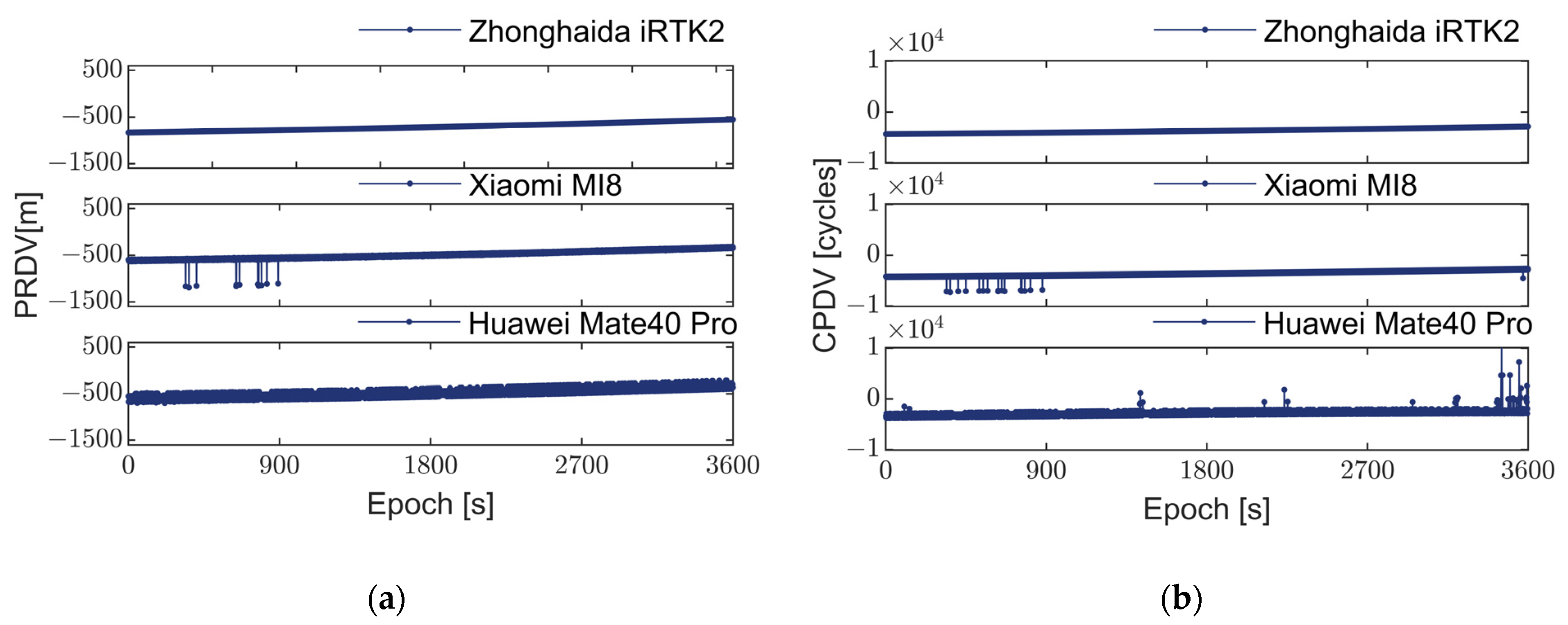
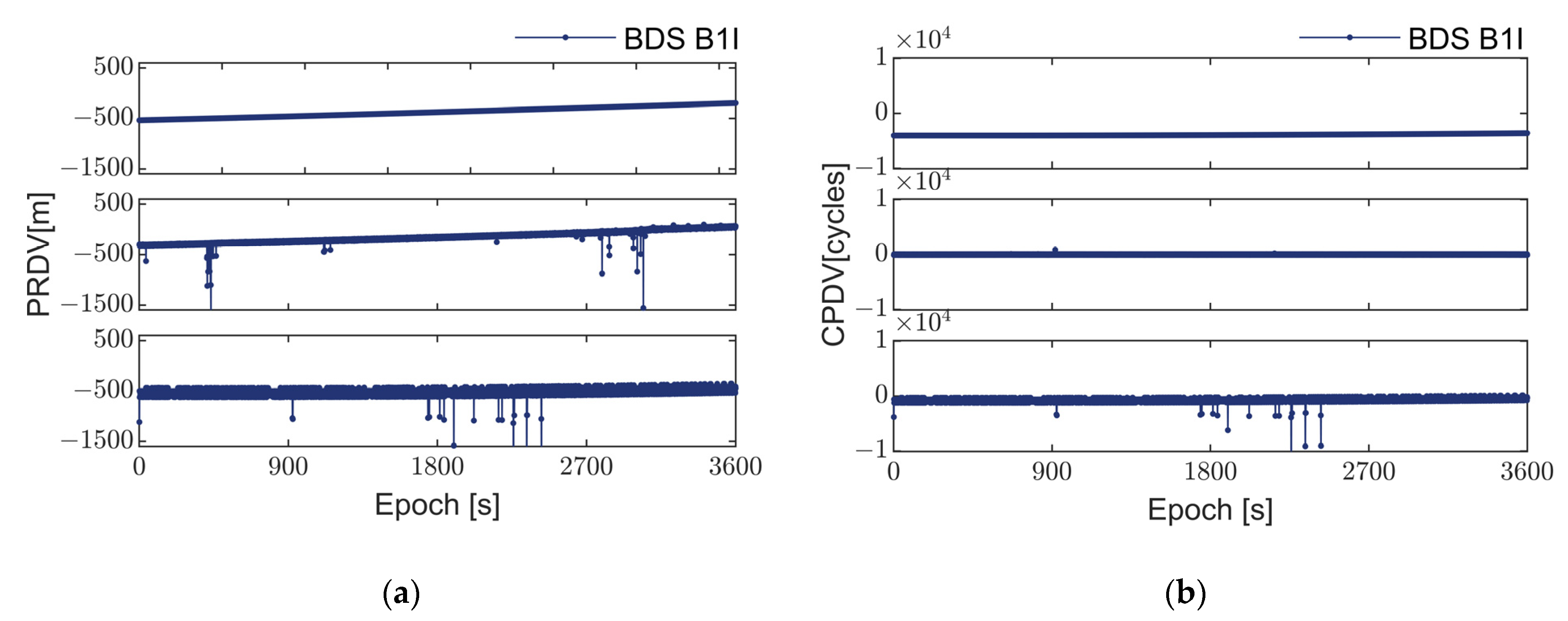
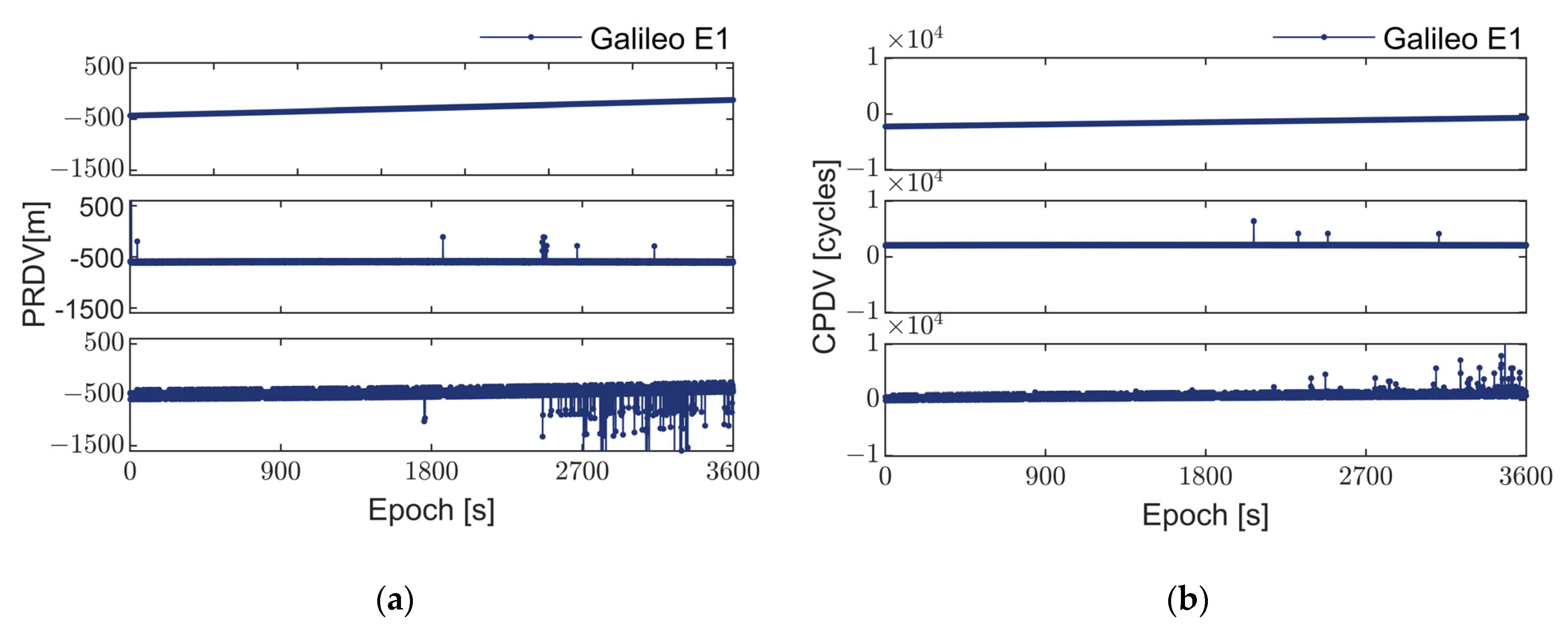
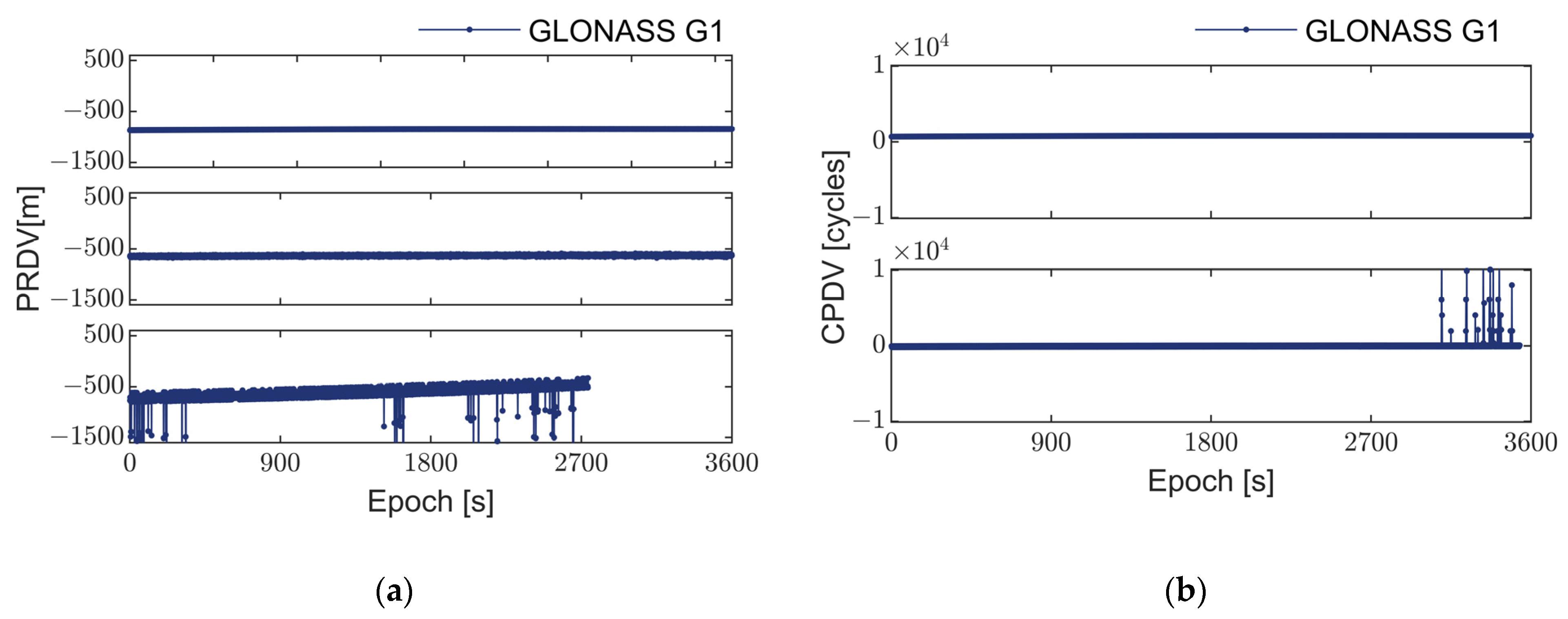
2.1.1. Analysis of Abnormal Errors in Land Pseudorange/Carrier Measurements

To minimize factors like multipath effects, an open university playground field was chosen for the experiment. The three receivers were placed within 5 cm of each other on a single platform. A one-hour static observation with a 1-s sampling interval was conducted. See Figure 1 for details on the observation environment and receivers’ placement.
This section focuses solely on the analysis of acquired observations from the first frequency of each GNSS system listed in the second column of Table 1 [35]. Following the acquisition of GNSS observations, single-differenced observations between epochs were analyzed in a static environment for the pseudorange and carrier phase observations from both smartphones and geodetic receivers. Figure 2, Figure 3, Figure 4 and Figure 5 depict the single-differenced pseudorange and carrier phase observations from the geodetic receiver and the two smartphones.
A quantitative analysis was conducted to show the characteristics of abnormal errors in smartphone observations under various environmental conditions and frequencies. A third-order derivative method was used to calculate the noise values of pseudorange and carrier phase, followed by the determination of the standard deviation (STD). An observation epoch was considered to contain abnormal errors if it exceeded twice the standard deviation [36]. Finally, a statistical analysis of the occurrence of abnormal errors across observation epochs was performed. Detailed results are presented in Table 2 and Table 3.
As depicted in Figure 2, Figure 3, Figure 4 and Figure 5, the pseudorange and carrier phase observation data from various GNSS systems, recorded by the geodetic receiver during a one-hour static observation experiment, display continuous and smooth trends. These observations show no significant outliers or systematic errors. Consequently, it can be inferred that under favorable observation conditions, the observation values from different GNSS systems should theoretically exhibit smoothness and are less likely to manifest in systematic errors or outliers.
However, the pseudorange and carrier phase observation values obtained from the two smartphones exhibit significant fluctuations and present frequent outliers. These outliers are prevalent across different systems and models of smartphones, indicating that the cause of such outliers is not attributed to satellite signals or propagation paths but rather to issues at the receiver end. It can also be seen from Table 2 that these outliers do not follow a consistent pattern and appear in both pseudorange and carrier phase observations. Therefore, they cannot be simply categorized as cycle slips [37].
Through comparative analysis of the pseudorange and carrier phase observation values from the Huawei Mate 40 Pro and Xiaomi Mi 8 smartphones, it was observed that the frequency of outliers in the Huawei Mate 40 Pro is significantly higher than that in the Xiaomi Mi 8. This suggests a notable difference in performance between the two devices. Particularly, as illustrated in Figure 5a, smartphones in the positioning process not only encounter issues with observation data quality but may also experience satellite signal loss. These outliers may stem from hardware limitations such as the linearly polarized antenna, low-precision clock, and low-cost GNSS chip adopted in smartphones. Given the considerable gap between smartphones and geodetic receivers in terms of satellite tracking count, observation frequency, and data quality, it is imperative to utilize existing observation values fully. This can be achieved by eliminating the outliers to enhance the overall quality of observation values, thereby further improving the positioning performance and accuracy of smartphones.

2.1.2. Analysis of Abnormal Errors in Water Pseudorange/Carrier Measurements

As shown in Section 2.1.1, smartphone pseudorange and carrier phase observations exhibit numerous abnormal errors in land environments. Navigation in water is also an important application of GNSS. Thus, to investigate the characteristics of abnormal errors in smartphone GNSS observations during water navigation, this study analyzes epoch-to-epoch differential values of GPS L1, L5, and BDS B1I B1C frequency pseudoranges and carrier phases by placing two smartphones on a platform mounted on a boat for kinematic testing. The experiment took place along the Yanshao Line route in Yancheng City, Jiangsu Province, China. Data were gathered during one hour with a sampling interval of 1 s. Figure 6 and Figure 7 depict the pseudorange and carrier phase differential values of the two smartphones in a water environment.
Figure 6 and Figure 7 illustrate the abnormal errors in GNSS observations from smartphones during water navigation. The presence of multipath effects, caused by fluctuations and reflections on the water surface, substantially amplifies both the magnitude and frequency of these anomalies compared to terrestrial environments. As seen from Table 2 and Table 3, the percentage of this type of abnormal error reaches a maximum of 6.90% in the experiments conducted on land. In contrast, in the kinematic experiments conducted on water, the rate peaks at 48.53%, occupying almost half of the observed epochs. The linearly polarized antennas typically employed in smartphones have limited capability to mitigate multipath effects, thereby exacerbating their influence on these observations.
Additionally, there are differences in the occurrence epochs and magnitude of abnormal errors in observation values across various GNSS systems and frequencies. In theory, observation values at the GPS L5 frequency should exhibit better quality than those at the L1 frequency. As shown in Table 3, the percentage of abnormal errors in the carriers of GPS L1 and L5 for the Xiaomi Mi8 smartphone is 39.21% and 36.32%, respectively. The difference between these two percentages is minimal. Similarly, the percentage of abnormal errors in the pseudorange of GPS L1 and L5 for the Huawei Mate 40 Pro smartphone is 38.84% and 34.27%, respectively. The advantage of L5 is not obvious in the smartphone. Moreover, as depicted in Figure 7b, the carrier data integrity of the Huawei Mate 40 Pro is notably lower, particularly with the BDS B1C frequency where the data discontinue at around 1000 epochs.
Considering the challenges related to the quality of acquired observables, available satellite count, and frequency of abnormal errors in smartphones, there is an urgent need to devise an error detection and elimination method tailored to these characteristic errors. This method should aim to enhance the quality of GNSS observation values acquired by smartphones.

2.2. Design of Detection and Repair Solutions

Based on the conditions mentioned above, real-time detection and reparation are performed on the pseudorange and carrier of each frequency obtained by the smartphone. The methodology initiates by using predicted values derived from Kalman filtering [38] to calculate the difference compared to the observed values. Subsequently, abnormal errors in the observations are identified in real time by evaluating whether these differences exceed predefined thresholds. Finally, depending on the presence of abnormal errors within the epoch, three distinct strategies are formulated to facilitate real-time repairs for these anomalies.

2.2.1. Establishment of State Equations

By establishing the satellite-to-ground distance state equation of the Kalman filter, the satellite-to-ground distance change can be predicted, and its predicted value can be used to correct abnormal errors. The satellite-to-ground distance ρ at the k epoch time is differentiated between epochs to obtain the differential component, as follows:
Δ ρ k 1 = ρ k ρ k 1
According to the motion characteristics of GNSS satellites, differential correction can be expressed as a second-order recursive equation
Δ ρ k = Δ ρ k 1 + Δ ρ ˙ k 1 t + Δ ρ ¨ k 1 2 t 2 + w k 1 6 t 3 Δ ρ ˙ k = Δ ρ ˙ k 1 + Δ ρ ¨ k 1 t + w k 1 2 t 2 Δ ρ ¨ k = Δ ρ ¨ k 1 + w k 1 t
where t represents the sampling interval, Δ ρ ˙ k denotes the rate of change in the satellite-to-ground distance, Δ ρ ¨ k represents the acceleration of the satellite-to-ground distance change, and w k 1 ~ N 0 , D w w stands for the system’s kinematic noise.
Taking the state vector as
X k = Δ ρ k , Δ ρ ˙ k , Δ ρ ¨ k T
The state equation can be represented as
X k = F X k 1 + G w k 1
where F and G represent the system state transition matrix and the kinematic noise matrix, respectively.
F = 1 t t 2 / 2 0 1 t 0 0 1
G = t 3 / 6 t 2 / 2 t
The state equation established through Equation (4) can effectively fit and predict the motion state of GNSS satellites.

2.2.2. Establishment of Observation Equations

By establishing the observation equation, it is possible to utilize the observed measurement information to update the state equation, thereby enhancing the accuracy of the state equation. Suppose P k , i represents the pseudorange of frequency i at time k and φ k , i represents the carrier of frequency i at time k . Utilizing Equation (1), the differential observation value can be obtained.
Δ P k , i = P k + 1 , i P k , i Δ φ k , i = φ k + 1 , i φ k , i
Furthermore, the variance can be calculated as
D ( Δ P k , i ) = 2 δ p 2 D ( Δ φ k , i ) = 2 δ φ 2
where σ P 2 and σ φ 2 represent the variance of pseudorange and carrier observation values, respectively.
The observation equation can be formulated as follows:
δ ρ k = Δ P k , i + ε P 1 λ i δ ρ k = Δ φ k , i + ε φ
where ε P and ε φ represent the observation errors of pseudorange and carrier, respectively, and λ i represents the wavelength of frequency i .
Let
L k , i = δ P k , i δ φ k , i ~ E L k , i , D Z Z
H = 1 0 0 1 λ i 0 0 V = ε P ε φ
Then, the observation equation can be represented as
L k , i = H k X k + V
where H is the observation matrix and V is the measurement noise matrix.

2.2.3. Abnormal Detection Solution Computation

Before using the Kalman filter for computation, it is necessary to provide appropriate initial values and variances for the state vector. Since the carrier observation values exhibit high precision, the differential satellite-to-ground distance Δ ρ 1 between epochs at the initial time can be obtained through carrier phase measurements [39]. Given the stability of obtaining GPS L1 frequency carrier observations from smartphones, calculations of the satellite-to-ground distance are conducted using carrier measurements at the following frequency:
Δ ρ 1 = λ 1 Δ φ 1
Subsequently, deduce the initial rate of change Δ ρ ˙ 1 and acceleration Δ ρ ¨ 1 of the satellite-to-ground distance at the initial time.
Δ ρ ˙ 1 = Δ ρ 2 Δ ρ 1 t Δ ρ ¨ 1 = Δ ρ ˙ 2 Δ ρ ˙ 1 t
The initial values of the state vector can be determined as follows:
X 1 = Δ ρ 1 , Δ ρ ˙ 1 , Δ ρ ¨ 1 T
Assuming that the initial state components are independent of each other, let σ φ 1 2 be the variance of the original carrier of GPS L1 frequency at the initial epoch. Based on Equation (15), according to the law of error propagation, the initial variance can be obtained, as follows:
D [ X 1 ] = 2 σ φ 1 2 D [ X ˙ 1 ] = D [ δ Δ ρ 2 δ Δ ρ 1 t 2 ] = 4 σ φ 1 2 t 2 D [ X ¨ 1 ] = D [ δ Δ ρ ˙ 2 δ Δ ρ ˙ 1 t 4 ] = 8 σ φ 1 2 t 4
The initial variance can be expressed as
D [ X 1 ] = d i a g 2 σ φ 1 2 , 4 σ φ 1 2 t 2 , 8 σ φ 1 2 t 4
Once the initial values and variances of the state vector are determined, the filtering recursion can be carried out.
Using the state equation, the predicted value of the satellite-to-ground distance can be recursively obtained. In theory, this value should be close to the observed value. Therefore, the difference between the predicted and observed values is calculated, and if it exceeds a predefined threshold, it indicates the presence of abnormal errors in the observations of that epoch.
Given the state vector at epoch k 1 , it is possible to recursively derive the state at epoch k , as follows:
X k = F X k 1
and the variance, as follows:
D ( X k ) = F D ( X k 1 ) F T + G D w w G T
The predicted value Δ ρ k of the satellite-to-ground distance can be obtained through X k .
By using Equations (7) and (8), we can obtain the pseudorange and carrier Δ P k , i and Δ φ k , i , along with their variances. Moreover, we can then calculate the difference between the predicted and observed values, as follows:
Δ P k , i = Δ P k , i Δ ρ k Δ φ k , i = Δ φ k , i Δ ρ k
and the variance of the difference is as follows:
D ( Δ P k , i ) = D ( X k ) + D ( Δ P k , i ) D ( Δ φ k , i ) = D ( X k ) + D ( Δ φ k , i )
When
Δ P k , i > 2 D ( Δ P k , i ) Δ φ k , i > 2 D ( Δ φ k , i )
it is considered that the pseudorange or carrier of frequency i at epoch k contains abnormal errors.
When at time k , both Δ P k , i and Δ φ k , i satisfy
Δ P k , i < 2 D ( Δ P k , i ) Δ φ k , i < 2 D ( Δ φ k , i )
the observations at k time are considered normal and do not need to be repaired.

2.2.4. Abnormal Repair Solution Computation

After completing the detection of abnormal errors, it is necessary to perform real-time repair on the observation values within that epoch containing abnormal errors. If some of the observation values within that epoch are abnormal data, the observation equation can be established using Equation (9) for the normal data in the observation values, yielding the Kalman gain matrix.
K k = D ( X k ) H k T ( H k D ( X k ) H k T + D z z ) 1
Subsequently, the optimal estimate of the state vector can be obtained
X ˜ k = X k + K k ( L k + 1 H X k )
and the variance is as follows:
D ( X ˜ k ) = ( I K k H k ) D ( X k ) ( I K k H k ) T + K k D w w K k T
For the abnormal set of data, Equation (25) is utilized to obtain the state vector X ˜ k , which in turn leads to the optimal valuation of the star-earth distance Δ ρ ˜ k . The abnormal data are replaced as follows:
Δ P ^ k , i = Δ ρ ˜ k Δ φ ^ k , i = 1 λ i Δ ρ ˜ k
where Δ P ^ k , i and Δ φ ^ k , i denote the amount of star-earth distance replaced by the optimal valuation.
The repair of the observation values is as follows:
P ¯ k , i = Δ P ^ k , i + P k 1 , i φ ¯ k , i = Δ φ ^ k , i + φ k 1 , i
where P ¯ k + 1 , i and φ ¯ k + 1 , i denote the restored pseudorange and carrier.
If all observation values within the epoch exhibit abnormal errors, then the predicted satellite-to-ground distance Δ ρ k calculated using Equation (18) is used to replace the abnormal data, as follows:
Δ P ^ k , i = Δ ρ k Δ φ ^ k , i = 1 λ i Δ ρ k
The repair of the observation values is as follows:
P ¯ k , i = Δ P k , i + P k 1 , i φ ¯ k , i = Δ φ k , i + φ k 1 , i
At this point, the repair of abnormal errors in the pseudorange and carrier has been completed.
As the number of epochs increases, the predicted values of the satellite-to-ground distance derived from the state equation become more accurate, providing more precise predictions and variances. For epochs with abnormal errors, especially those with significant errors, the repair is performed using the optimal estimates obtained from filtering predictions and observations from other frequencies without abnormal errors. Figure 8 presents the flowchart of the real-time detection and repair method for abnormal errors in smartphone GNSS.
As depicted in Figure 8, the key steps of the abnormal error detection and repair method based on Kalman filtering are outlined as follows:
  • Equation establishment: The smartphone observation values are used to compute epoch-to-epoch differences, resulting in single-differenced observation values. These are used to establish the observation equations. The state vector includes the satellite-to-ground distance, rate of change, and acceleration, forming the system state equation;
  • Anomaly detection computation: After determining the initial values and variances of the system state, Kalman filtering is employed to predict the satellite-to-ground distance. Differences between predicted values and pseudorange and carrier observation values for each epoch are calculated alongside their standard deviations. The standard deviation multiplied by two serves as the threshold to ascertain whether the differences exceed acceptable limits;
  • Anomaly repair computation: Based on the anomalies identified in the second step, three scenarios are considered. First, if no abnormalities are detected in the epoch, the original observation values are directly output without any alterations. Second, if abnormalities are present in some observations within the epoch, normal observations are used to establish observation equations for subsequent Kalman filtering. The resultant filtered values replace the abnormal observations to rectify errors. Third, if all observations within the epoch exhibit abnormalities, predicted values replace the observations to rectify errors.

3. Results

To validate the effectiveness of the proposed abnormal error detection and repair scheme, as well as its performance in land and water environments, multiple sets of experiments were conducted using Xiaomi MI 8 and Huawei Mate 40 Pro smartphones. These experiments included static tests on a university campus field and kinematic tests while boating on a waterway. Furthermore, the experimental results were analyzed.

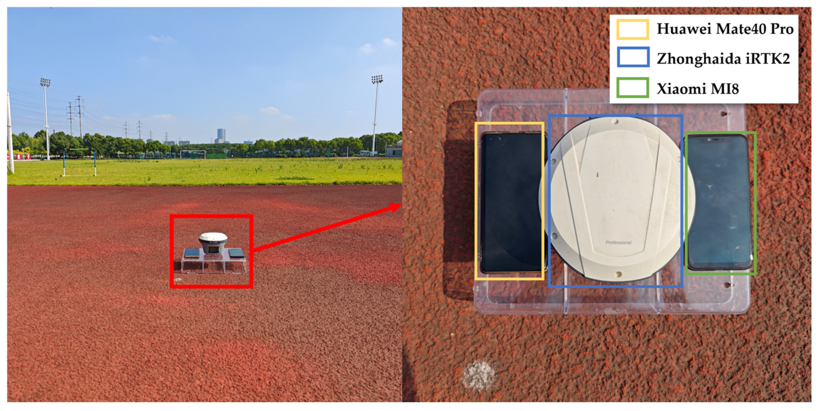
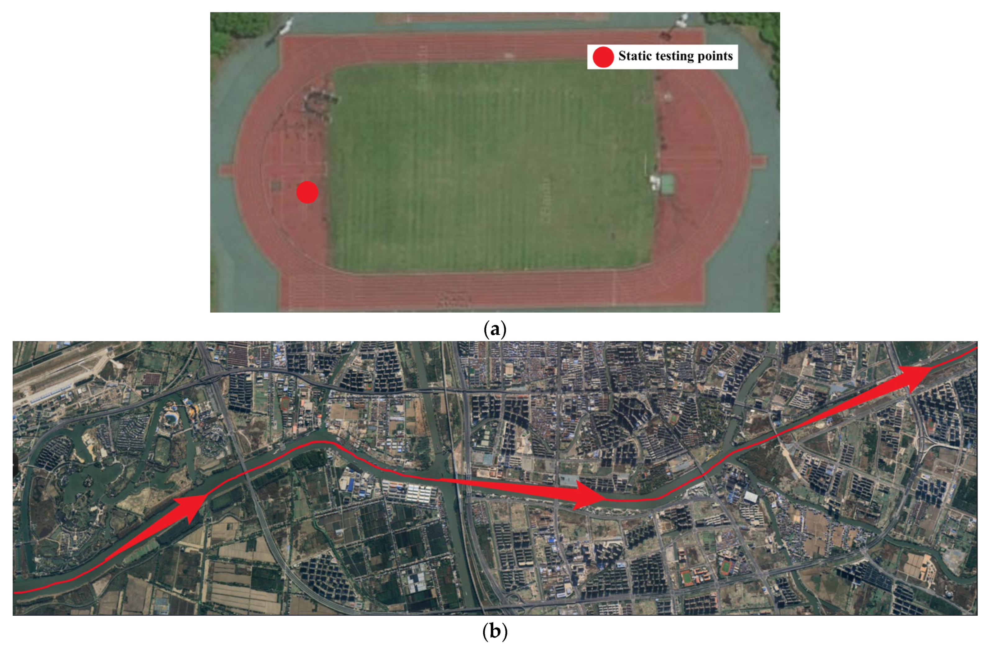
3.1. Experimental Description

The experiment on land consisted of multiple static tests conducted on the playground of Southeast University in Jiangsu Province, China, from May to June 2023. Xiaomi MI 8 and Huawei Mate 40 Pro smartphones were placed on a ground platform with a distance of less than 15 cm between them. Each set of static tests lasted for 1 h with a sampling interval of 1 s. The water experiment occurred on 16 August 2023 aboard a boat in the waterways of Yancheng City, Jiangsu Province, China. The experimental setup mirrored that of the land experiment. Each session lasted approximately 1 h with a sampling interval of 1 s. The test route traversed urban areas, introducing a relatively complex environment, and the cargo vessel maintained a speed of approximately 10 km/h. The test trajectory is depicted in Figure 9. To validate the effectiveness of the method, the proposed approach was compared with a method that constructs state test statistics using the state-estimated value and the state-predicted value, hereafter denoted as the State-Based method [40].

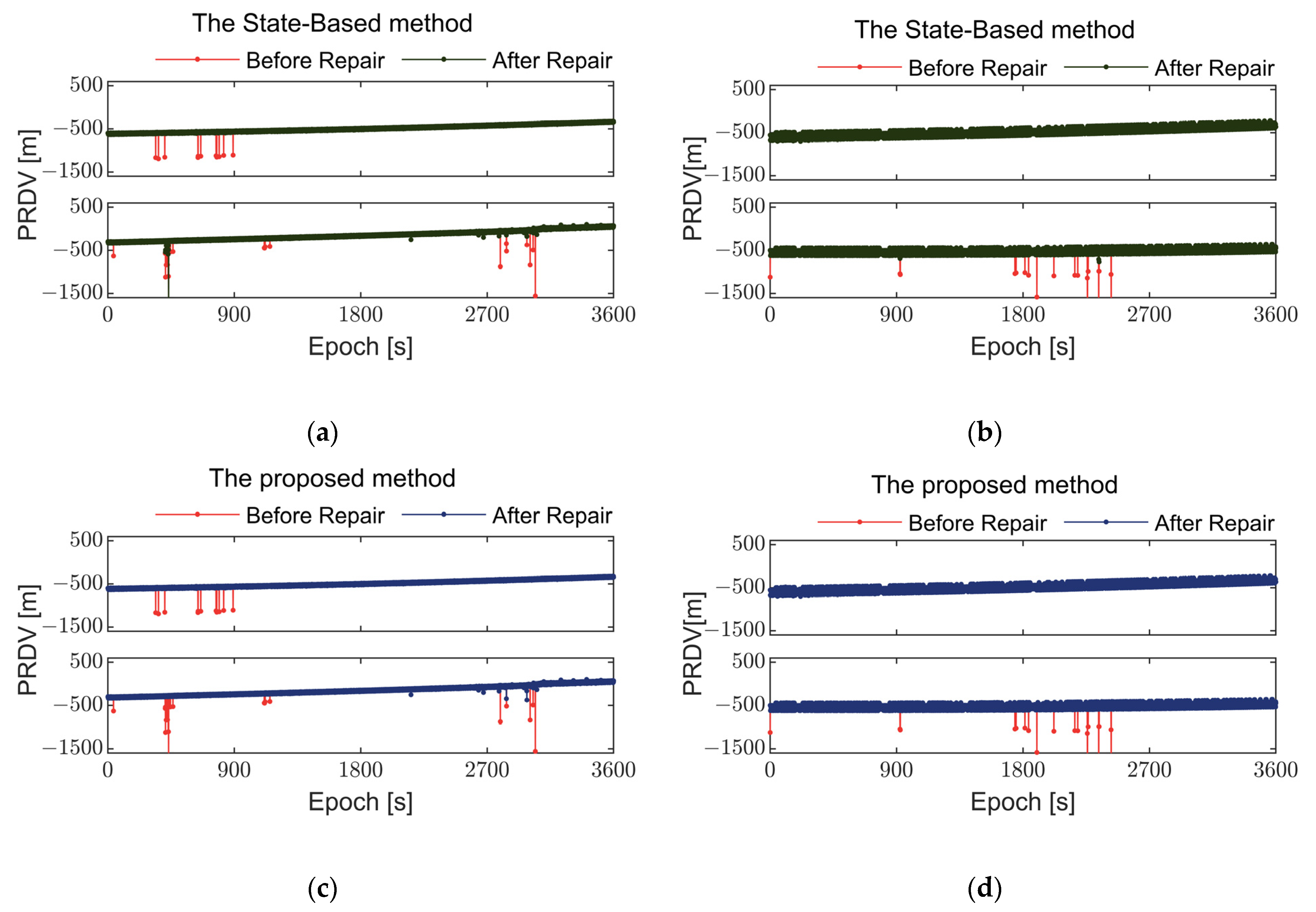
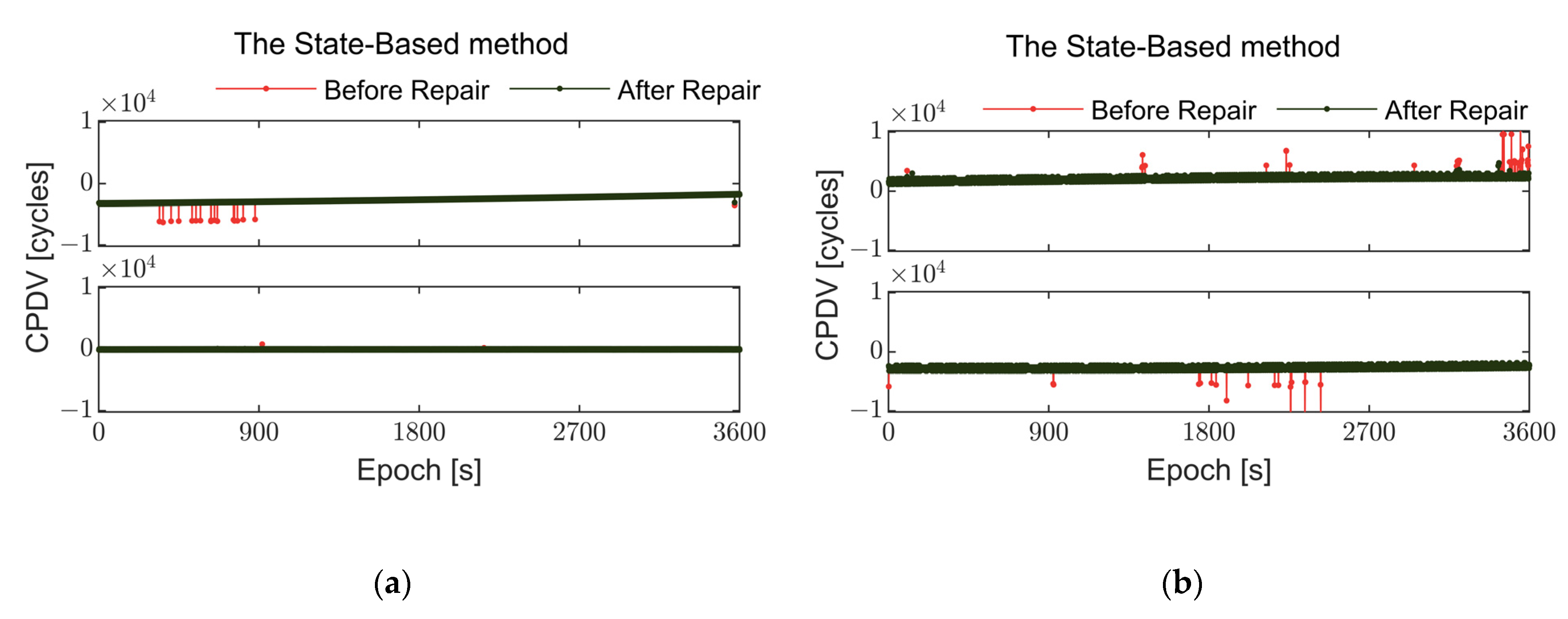
3.2. Performance Analysis of Detection and Repair Methods

To better showcase the effectiveness of the repair, the experiment evaluated the effectiveness of the repair method by comparing the pseudorange and carrier phase differentials before and after the repair. Due to the kinematic nature of real-time testing, conducting synchronous observations with a high-precision geodetic receiver and mobile phone for comparative analysis was not feasible. The observed values were fitted using the least squares method to generate a continuous and smooth curve. This curve was then utilized as a reference to quantitatively evaluate the effectiveness of the repair process.
The observations were processed using the real-time detection and repair methods proposed in this paper and the State-Based method to detect and repair abnormal errors. A comparison of the pseudorange and carrier before and after correction is presented, with the repair outcomes shown in Figure 10, Figure 11, Figure 12 and Figure 13.
Figure 10 and Figure 11 illustrate the comparison before and after repair of observation values for Xiaomi MI 8 and Huawei Mate 40 Pro during static land tests. In the open and spacious observation environment on land, the multipath effect is minimal, resulting in good quality observation values received by smartphones. However, during the observation process, significant fluctuations are observed in the values from most satellites, with only a few satellites showing nearly no abnormal errors. Compared to the Huawei Mate 40 Pro, the Xiaomi MI 8 experiences fewer abnormal errors. Although Huawei uses a different GNSS chip and antenna, this has not significantly improved the situation of abnormal errors in the observation values, necessitating the use of the algorithm proposed in this paper to enhance the quality of observations.
It can be seen that both methods are capable of repairing such abnormal errors. However, as shown in Figure 10c and Figure 11b, when abnormal errors occur frequently, the State-Based method struggles to effectively repair these observations. In contrast, the method proposed in this paper shows a better capability to detect and repair abnormal errors even under such challenging conditions.
Table 4 and Table 5 compare standard deviations of pseudorange and carrier phase observations for different satellites before and after repair during land positioning for the two smartphones used in this experiment. In most cases, the standard deviations decrease after repair, indicating that the repair method effectively improves the quality of observations. Specifically, for Xiaomi MI 8, satellites G02 and C01 exhibit significant reductions in pseudorange and carrier phase standard deviations after repair. Additionally, the proposed method in this paper outperforms the State-Based method by approximately 10% in the land experiment.
However, in certain cases, the standard deviations after repair did not show significant improvement. For instance, the pseudorange observations of the G02 satellite for Huawei Mate40 Pro did not change in standard deviation before and after repair, as there were no abnormal errors present in its pseudorange observations during the observation process; thus, the method did not correct it. Additionally, there are variations in the standard deviation changes before and after repair among different smartphones and satellite numbers. Comparing the performance of the two smartphones, it is evident that in certain cases, the Huawei Mate40 Pro exhibits improved standard deviations post-repair compared to the Xiaomi Mi 8. This difference may stem from variations in the GNSS chips and antennas employed in these smartphones.
Figure 12 and Figure 13 depict the observation repair results during kinematic testing on water for two smartphones. During water positioning, the frequency and magnitude of abnormal errors in observations are significantly higher than on land, indicating that smartphones equipped with linearly polarized antennas have almost no capability to resist multipath effects. In Figure 13, the GPS L1 frequency observations of the Huawei Mate 40 Pro exhibit numerous and continuous abnormal errors, whereas BDS B1I frequency observations show fewer abnormal errors.
In Figure 12, the BDS B1I frequency data of the Xiaomi MI 8 display abnormal errors around epoch 1500 that were not repaired in real time. This may be due to an inadequate threshold setting during filtering to detect abnormal errors or because other frequency data at that moment also contained abnormal errors, making it impossible to utilize them for repair. The State-Based method, when faced with a large number of abnormal errors during water testing, often fails to repair these errors adequately due to the lack of sufficient measurement information, leading to the replacement of some erroneous observations with predicted values, which is not sufficiently accurate. In contrast, the method proposed in this paper, by making full use of multi-frequency data, is able to better repair abnormal errors even under such conditions.
Table 6 and Table 7 present the standard deviations of observations before and after repair for two smartphones across different systems. By applying the method proposed in this paper to correct abnormal errors in observations, the standard deviations of observations from various satellites have all been reduced, enhancing data quality. Specifically, observations of carrier quality were poorer without methodological repair, particularly for satellite G05, where the carrier standard deviations for the two smartphones were 377.612 m and 240.025 m, much lower than those of geodetic receivers. Such poor-quality observations are challenging to utilize in high-precision positioning. However, after repair using the method, the standard deviations of observations improved to 59.233 m and 40.598 m, respectively, representing a quality improvement of nearly 83%. The repair effect of the method proposed in this paper is 10–35% better than the State-Based method.
The improvement in observation quality varies for different observations, primarily depending on the quantity and magnitude of abnormal errors present. Taking the pseudorange observations of satellites G05 and G17 with the Xiaomi MI 8 smartphone as an example, the standard deviation of G05 satellite pseudorange was 173.341 m before repair and improved to 51.287 m after repair, a quality improvement of 70.42%. For the G17 satellite, the improvement was 86.04%. Additionally, based on the original pseudorange observations of the two satellites, it is evident that the G17 satellite observations contained significantly higher quantities and magnitudes of abnormal errors compared to the G05 satellite.

4. Discussion

Comparison between the GNSS observations obtained from geodetic receivers and smartphones revealed distinct characteristics. Geodetic receiver data exhibited a consistent smooth trend with no abnormal or systematic errors. In contrast, smartphone observations displayed noticeable fluctuations and frequent outliers. Given the limited availability of dual-frequency data and fewer visible satellites for smartphones, optimizing the utilization of acquired observations is essential to enhance the quality of smartphone-derived observations [41,42].
An analysis of experimental results in both land and water environments reveals that the abnormal errors in smartphone GNSS observations do not exhibit a clear pattern. The frequency of outliers in the Huawei Mate 40 Pro smartphone is higher than in the Xiaomi Mi 8. While the Huawei Mate 40 Pro is more advanced than the Xiaomi Mi 8, the quality of its observational data does not match that of older models. This suggests that current smartphone hardware, such as GNSS chips, has not undergone significant improvements. The positioning performance of smartphones is severely constrained by hardware limitations. Abnormal errors vary across different systems, satellites, and smartphones, with pseudorange errors reaching up to 6000 m. Carrier phase errors can reach tens of thousands of cycles. kinematic and static tests indicate that these abnormal errors are closely correlated with the quality of the observation environment, with users often encountering severe multipath effects in practical usage scenarios.
The real-time detection and repair method proposed in this paper performed well in both environments, effectively reducing abnormal errors and improving data quality. In water environments, the frequency and magnitude of abnormal errors in smartphone observations increased by almost 40%, affecting positioning accuracy and stability. After repair using the proposed method, the standard deviation noticeably decreased, especially for lower-quality observations, with a more pronounced enhancement effect. For observations of lower quality, the standard deviation of the observations after repair increased by over 80%. In certain instances, observation data were unaffected by abnormal errors and thus did not necessitate correction.
In our experiments, especially during tests conducted on water, there was a high probability of abnormal errors in the smartphone observations. As depicted in Figure 12a, within 100 epochs, more than 50 epochs contained observations with abnormal errors. Our proposed method is constrained when all frequency observations simultaneously exhibit prolonged anomalies without recent updates using measurement values. Moreover, as evidenced in Section 2.1 experiments, different smartphones employ varying hardware devices, leading to differing occurrences of abnormal errors in their observations. Our method uses twice the standard deviation as the threshold for anomaly detection, which may hinder effective real-time detection and repair of abnormal errors for some smartphones. Adapting the threshold to accommodate different smartphone hardware is a key focus of our future research.

5. Conclusions

This paper proposes a real-time detection and repair method to mitigate frequent abnormal errors in GNSS observations during smartphone navigation. Based on the continuous smoothness of pseudorange and carrier observations, this method establishes state equations and observation equations separately. It utilizes the residuals between the predicted state vector from the Kalman filter and the observed values. Real-time detection of abnormal errors in observations is achieved by determining whether the residuals exceed the current epoch threshold. Subsequently, using the optimal estimation derived from normal data, the abnormal observations are replaced in real time, thereby realizing the real-time repair of smartphone observations. The method employs data synthesis from multiple frequencies and systems to repair continuous abnormal errors. Compared to filtering individual observations in isolation, using multi-frequency multi-system data for simultaneous filtering and replacement can prevent a decrease in prediction accuracy and also mitigate the risk of filter divergence or instability in cases where continuous abnormal errors occur in a single observation.
To validate the effectiveness of the proposed abnormal error detection and repair solution, experiments were conducted using Xiaomi MI 8 and Huawei Mate 40 Pro smartphones at the Southeast University campus in Jiangsu Province, China, and in the waterway of Yancheng City. Multiple sets of static/kinematic experiments were performed. The experimental results show that the method effectively repaired various types of abnormal errors, especially continuous ones, by integrating data from multiple frequencies and systems. This approach successfully prevented degradation in prediction accuracy or filter divergence. In scenarios with frequent occurrences of abnormal errors in the observations, the method demonstrated a maximum enhancement of 93.47% in pseudorange quality and 86.61% in carrier phase quality in the most favorable cases. The method proposed in this paper outperformed the State-Based method by approximately 10% on land and by 10–35% on water. However, during the repair process, there may be 2–3% of abnormal errors that are not detected and repaired in real time. This could be attributed to the failure to establish appropriate thresholds for detecting abnormal errors.
The method demonstrates high stability and reliability in repairing observations. By comparing the standard deviations of observations before and after repair, it is verified that the method significantly reduces the influence of abnormal errors on observations, thereby enhancing data quality. This provides crucial support for achieving high-precision positioning with smartphones in scenarios heavily affected by multipath, such as maritime navigation, and contributes to improving their positioning accuracy and reliability.

Author Contributions

Methodology, H.M., X.Y. and A.A.-A.; software, H.M., J.W. and Y.W.; validation, H.M. and Y.W.; data curation, Y.W.; writing—original draft preparation, H.M.; writing—review and editing, A.A.-A. and J.W.; supervision, X.Y.; project administration, X.Y.; funding acquisition, X.Y. All authors have read and agreed to the published version of the manuscript.

Funding

This research was funded by the National Key R&D Program of China, grant number 2023YFB3907103.

Data Availability Statement

The raw data supporting the conclusions of this article will be made available by the authors on request.

Conflicts of Interest

The authors declare no conflicts of interest.

References

  1. Bahadur, B. A Study on the Real-Time Code-Based GNSS Positioning with Android Smartphones. Measurement 2022, 194, 111078. [Google Scholar] [CrossRef]
  2. Li, B.; Miao, W.; Chen, G.; Li, Z. Ambiguity Resolution for Smartphone GNSS Precise Positioning: Effect Factors and Performance. J. Geod. 2022, 96, 63. [Google Scholar] [CrossRef]
  3. Paziewski, J.; Fortunato, M.; Mazzoni, A.; Odolinski, R. An Analysis of Multi-GNSS Observations Tracked by Recent Android Smartphones and Smartphone-Only Relative Positioning Results. Measurement 2021, 175, 109162. [Google Scholar] [CrossRef]
  4. Wang, L.; Li, Z.; Wang, N.; Wang, Z. Real-Time GNSS Precise Point Positioning for Low-Cost Smart Devices. GPS Solut. 2021, 25, 69. [Google Scholar] [CrossRef]
  5. Yun, J.; Lim, C.; Park, B. Inherent Limitations of Smartphone GNSS Positioning and Effective Methods to Increase the Accuracy Utilizing Dual-Frequency Measurements. Sensors 2022, 22, 9879. [Google Scholar] [CrossRef]
  6. Aggrey, J.; Bisnath, S.; Naciri, N.; Shinghal, G.; Yang, S. Multi-GNSS Precise Point Positioning with next-Generation Smartphone Measurements. J. Spat. Sci. 2020, 65, 79–98. [Google Scholar] [CrossRef]
  7. Zhang, X.; Tao, X.; Zhu, F.; Shi, X.; Wang, F. Quality Assessment of GNSS Observations from an Android N Smartphone and Positioning Performance Analysis Using Time-Differenced Filtering Approach. GPS Solut. 2018, 22, 70. [Google Scholar] [CrossRef]
  8. Shinghal, G.; Bisnath, S. Conditioning and PPP Processing of Smartphone GNSS Measurements in Realistic Environments. Satell. Navig. 2021, 2, 10. [Google Scholar] [CrossRef]
  9. Weng, D.; Hou, Z.; Meng, Y.; Cai, M.; Chan, Y. Characterization and Mitigation of Urban GNSS Multipath Effects on Smartphones. Measurement 2023, 223, 113766. [Google Scholar] [CrossRef]
  10. Peng, Z.; Gao, Y.; Gao, C.; Shang, R.; Gan, L. Improving Smartphone GNSS Positioning Accuracy Using Inequality Constraints. Remote Sens. 2023, 15, 2062. [Google Scholar] [CrossRef]
  11. Liu, W.; Li, J.; Zeng, Q.; Guo, F.; Wu, R.; Zhang, X. An Improved Robust Kalman Filtering Strategy for GNSS Kinematic Positioning Considering Small Cycle Slips. Adv. Space Res. 2019, 63, 2724–2734. [Google Scholar] [CrossRef]
  12. Li, Z.; Wang, L.; Wang, N.; Li, R.; Liu, A. Real-Time GNSS Precise Point Positioning with Smartphones for Vehicle Navigation. Satell. Navig. 2022, 3, 19. [Google Scholar] [CrossRef]
  13. Lachapelle, G.; Gratton, P.; Horrelt, J.; Lemieux, E.; Broumandan, A. Evaluation of a Low Cost Hand Held Unit with GNSS Raw Data Capability and Comparison with an Android Smartphone. Sensors 2018, 18, 4185. [Google Scholar] [CrossRef] [PubMed]
  14. Paziewski, J.; Sieradzki, R.; Baryla, R. Signal Characterization and Assessment of Code GNSS Positioning with Low-Power Consumption Smartphones. GPS Solut. 2019, 23, 98. [Google Scholar] [CrossRef]
  15. Pesyna, K.M.; Heath, R.W.; Humphreys, T.E. Centimeter Positioning with a Smartphone-Quality GNSS Antenna. In Proceedings of the 27th International Technical Meeting of the Satellite Division of The Institute of Navigation (ION GNSS+ 2014), Tampa, FL, USA, 8–12 September 2014. [Google Scholar]
  16. Geng, J.; Jiang, E.; Li, G.; Xin, S.; Wei, N. An Improved Hatch Filter Algorithm towards Sub-Meter Positioning Using Only Android Raw GNSS Measurements without External Augmentation Corrections. Remote Sens. 2019, 11, 1679. [Google Scholar] [CrossRef]
  17. Kirkko-Jaakkola, M.; Söderholm, S.; Honkala, S.; Koivula, H.; Nyberg, S.; Kuusniemi, H. Low-Cost Precise Positioning Using a National GNSS Network. In Proceedings of the 28th International Technical Meeting of the Satellite Division of The Institute of Navigation (ION GNSS+ 2015), Tampa, FL, USA, 14–18 September 2015. [Google Scholar]
  18. Zabala Haro, M.; Martín Furones, Á.; Anquela Julián, A.; Jiménez-Martínez, M.J. Comprehensive Analysis of Xiaomi Mi 8 GNSS Antenna Performance. Sensors 2024, 24, 2569. [Google Scholar] [CrossRef]
  19. Tomaštík, J.; Chudá, J.; Tunák, D.; Chudý, F.; Kardoš, M. Advances in Smartphone Positioning in Forests: Dual-Frequency Receivers and Raw GNSS Data. For. Int. J. For. Res. 2021, 94, 292–310. [Google Scholar] [CrossRef]
  20. Gao, H.; Groves, P.D. Environmental Context Detection for Adaptive Navigation Using GNSS Measurements from a Smartphone: Environment Detection Using GNSS Measurements. J. Inst. Navig. 2018, 65, 99–116. [Google Scholar] [CrossRef]
  21. Tomaštík, J., Jr.; Tomaštík, J., Sr.; Saloň, Š.; Piroh, R. Horizontal Accuracy and Applicability of Smartphone GNSS Positioning in Forests. For. Int. J. For. Res. 2017, 90, 187–198. [Google Scholar] [CrossRef]
  22. Angrisano, A.; Gaglione, S. Smartphone GNSS Performance in an Urban Scenario with RAIM Application. Sensors 2022, 22, 786. [Google Scholar] [CrossRef]
  23. Ch, V.R.; Alekhya, N.L.; Rahaman, M.M.; Imran, M.; Pujasri, K.; Killamsetti, H.K. Analyzing Multipath Fading in Deep Water Through Signal to Noise Ratio. In Proceedings of the 2024 International Conference on Integrated Circuits and Communication Systems (ICICACS), Raichur, India, 23 February 2024; pp. 1–4. [Google Scholar]
  24. Tranquilla, J.M.; Carr, J.P. GPS Multipath Field Observations at Land and Water Sites. Navigation 1990, 37, 393–414. [Google Scholar] [CrossRef]
  25. Zangenehnejad, F.; Gao, Y. GNSS Smartphones Positioning: Advances, Challenges, Opportunities, and Future Perspectives. Satell. Navig. 2021, 2, 24. [Google Scholar] [CrossRef] [PubMed]
  26. Paziewski, J. Recent Advances and Perspectives for Positioning and Applications with Smartphone GNSS Observations. Meas. Sci. Technol. 2020, 31, 091001. [Google Scholar] [CrossRef]
  27. Specht, C.; Dabrowski, P.S.; Pawelski, J.; Specht, M.; Szot, T. Comparative Analysis of Positioning Accuracy of GNSS Receivers of Samsung Galaxy Smartphones in Marine Dynamic Measurements. Adv. Space Res. 2019, 63, 3018–3028. [Google Scholar] [CrossRef]
  28. Bai, T.; Chai, H.; Wang, M.; Tian, X.; Du, Z.; Zhang, F. Analysis of GNSS Data Quality and Dynamic Positioning Assessment on Smartphones at Sea. Hydrogr. Surv. Mapp. 2022, 42, 42–47. [Google Scholar]
  29. Robustelli, U.; Paziewski, J.; Pugliano, G. Observation Quality Assessment and Performance of GNSS Standalone Positioning with Code Pseudoranges of Dual-Frequency Android Smartphones. Sensors 2021, 21, 2125. [Google Scholar] [CrossRef]
  30. Pan, C.; Li, Z.; Zhang, Q.; Soja, B.; Gao, J. Smartphone-Based Vision/MEMS-IMU/GNSS Tightly Coupled Seamless Positioning Using Factor Graph Optimization. Measurement 2024, 229, 114420. [Google Scholar] [CrossRef]
  31. Blewitt, G. An Automatic Editing Algorithm for GPS Data. Geophys. Res. Lett. 1990, 17, 199–202. [Google Scholar] [CrossRef]
  32. Zhang, X.; He, X.; Liu, W. Characteristics of Systematic Errors in the BDS Hatch–Melbourne–Wübbena Combination and Its Influence on Wide-Lane Ambiguity Resolution. GPS Solut. 2017, 21, 265–277. [Google Scholar] [CrossRef]
  33. Li, Y.G. Zuofa Cycle Slip Detection and Ambiguity Resolution Algorithms for Dual-Frequency GPS Data Processing. Mar. Geod. 1999, 22, 169–181. [Google Scholar] [CrossRef]
  34. Li, W.; Song, J.; Li, J.; Zhu, X. Improving GNSS Positioning Performance of Android Smart Devices by a Novel Pseudorange Correction Method. Meas. Sci. Technol. 2023, 34, 045010. [Google Scholar] [CrossRef]
  35. Li, M.; Huang, T.; Li, W.; Zhao, Q.; Jiang, K. Precise Point Positioning with Mixed Single- and Dual-Frequency GNSS Observations from Android Smartphones Considering Code-Carrier Inconsistency. Adv. Space Res. 2023, 74, 2664–2679. [Google Scholar] [CrossRef]
  36. Li, G.; Geng, J. Characteristics of Raw Multi-GNSS Measurement Error from Google Android Smart Devices. GPS Solut. 2019, 23, 90. [Google Scholar] [CrossRef]
  37. Chen, K.; Chang, G.; Chen, C.; Zhu, T. An Improved TDCP-GNSS/INS Integration Scheme Considering Small Cycle Slip for Low-Cost Land Vehicular Applications. Meas. Sci. Technol. 2021, 32, 055006. [Google Scholar] [CrossRef]
  38. Zhao, J.; Wang, J.; Han, H.; Jiang, T. A Study on the Model of Robust Fractional-Order Extended Kalman Filtering with Gross Error. GPS Solut. 2024, 28, 87. [Google Scholar] [CrossRef]
  39. Xia, S.; Yu, X. A GNSS Triple-Frequency Combination Cycle Slip Detection and Repair Method without Blind Spots. Sci. Surv. Mapp. 2020, 45, 62–69. [Google Scholar] [CrossRef]
  40. Sun, A.; Zhang, Q.; Yu, Z.; Meng, X.; Liu, X.; Zhang, Y.; Xie, Y. A Novel Slow-Growing Gross Error Detection Method for GNSS/Accelerometer Integrated Deformation Monitoring Based on State Domain Consistency Theory. Remote Sens. 2022, 14, 4758. [Google Scholar] [CrossRef]
  41. Gao, R.; Xu, L.; Zhang, B.; Liu, T. Raw GNSS Observations from Android Smartphones: Characteristics and Short-Baseline RTK Positioning Performance. Meas. Sci. Technol. 2021, 32, 084012. [Google Scholar] [CrossRef]
  42. Zangenehnejad, F.; Gao, Y. Quality Analysis of Smartphone Gnss Observations and Impact on Precise Positioning. Int. Arch. Photogramm. Remote Sens. Spat. Inf. Sci. 2023, 48, 1169–1177. [Google Scholar] [CrossRef]
Figure 1. The layout of two smartphones and a geodetic receiver (right) at an open observation point on the university playground field (left).
Remotesensing 16 03117 g001
Figure 2. Observations of GPS satellite G03. The horizontal axis represents epochs, while PRDV (pseudorange single-differenced values between epochs) and CPDV (carrier phase single-differenced values between epochs) are depicted on the vertical axis. (a) Illustrates the single-differenced pseudorange between epochs for three receivers listed from top to bottom: Zhonghaida iRTK2, Xiaomi MI8 smartphone, and Huawei Mate40 Pro smartphone; (b) Displays the single-differenced carrier phase between epochs for the same receivers.
Remotesensing 16 03117 g002
Figure 3. Observations of BDS satellite C17. (a) Illustrates the single-differenced pseudorange between epochs for three receivers listed from top to bottom: Zhonghaida iRTK2, Xiaomi MI8 smartphone, and Huawei Mate40 Pro smartphone; (b) Displays the single-differenced carrier phase between epochs for the same receivers.
Remotesensing 16 03117 g003
Figure 4. Observations of Galileo satellite E05. (a) Illustrates the single-differenced pseudorange between epochs for three receivers listed from top to bottom: Zhonghaida iRTK2, Xiaomi MI8 smartphone, and Huawei Mate40 Pro smartphone; (b) Displays the single-differenced carrier phase between epochs for the same receivers.
Remotesensing 16 03117 g004
Figure 5. Observations of GLONASS satellite R22. (a) Illustrates the single-differenced pseudorange between epochs for three receivers listed from top to bottom: Zhonghaida iRTK2, Xiaomi MI8 smartphone, and Huawei Mate40 Pro smartphone; (b) Displays the single-differenced carrier phase between epochs for the same receivers. The Huawei Mate40 Pro is unable to track GLONASS carrier phase observations.
Remotesensing 16 03117 g005
Figure 6. Observations of GPS satellite G05 and BDS satellite B10. Comparison of pseudorange differential values on water between two smartphones with different systems: (a) Xiaomi MI8 smartphone and (b) Huawei Mate40 Pro smartphone. From top to bottom, the figures display observations of GPS L1 and L5 frequencies and BDS B1I and/or BDS B1C frequencies, respectively. It should be noted that the Xiaomi MI8 cannot acquire BDS B1C data.
Remotesensing 16 03117 g006
Figure 7. Observations of GPS satellite G20 and BDS satellite B05. Comparison of carrier phase differential values over water between two smartphones with different systems: (a) Xiaomi MI8 smartphone and (b) Huawei Mate40 Pro smartphone.
Remotesensing 16 03117 g007
Figure 8. Flowchart of real-time detection and repair method of abnormal errors in smartphone GNSS observations.
Remotesensing 16 03117 g008
Figure 9. Smartphone testing in different environments. (a) Static test site on the land playground. (b) Waterway kinematic test track. The red line represents the navigation track and the red arrow indicates the navigation direction.
Remotesensing 16 03117 g009
Figure 10. Comparison of GNSS pseudorange differentials before and after repair using different methods during static tests on land for two smartphones. The red line represents the uncorrected observations, the green line indicates the results after repair using the State-Based method, and the blue line shows the results after repair using the method proposed in this paper. Subplots (a,b) show results obtained using the State-Based method, while subplots (c,d) display results from the method proposed in this paper. (a,c) show observed pseudorange differentials of GPS L1 frequency from satellite G02 and BDS B1I frequency from satellite C01 on the Xiaomi MI 8 smartphone, while (b,d) show corresponding observations on the Huawei Mate 40 Pro smartphone. This presentation format remains consistent across Figure 10, Figure 11, Figure 12 and Figure 13.
Remotesensing 16 03117 g010
Figure 11. Comparison of GNSS carrier phase differentials before and after repair using different methods during static tests on land for two smartphones. (a,c) show Xiaomi MI 8 smartphone, observed carrier phase differentials of GPS L1 frequency from satellite G02 and BDS B1I frequency from satellite C01. (b,d) show Huawei Mate 40 Pro smartphone, observed carrier phase differentials of GPS L1 frequency from satellite G02 and BDS B1I frequency from satellite C01.
Remotesensing 16 03117 g011aRemotesensing 16 03117 g011b
Figure 12. Comparison of GNSS pseudorange differentials before and after repair using different methods during kinematic tests on water for two smartphones. (a,c) show Xiaomi MI 8 smartphone, observed pseudorange differentials of GPS L1 frequency from satellite G04 and BDS B1I frequency from satellite C07. (b,d) show Huawei Mate 40 Pro smartphone, observed carrier phase differentials of GPS L1 frequency from satellite G04 and BDS B1I frequency from satellite C07. Similar to the land experiment, the green line represents the results repaired by the State-Based method, while the blue line represents the results repaired by the method proposed in this paper.
Remotesensing 16 03117 g012
Figure 13. Comparison of GNSS carrier phase differentials before and after repair using different methods during kinematic tests on water for two smartphones. (a,c) show Xiaomi MI 8 smartphone, observed carrier phase differentials of GPS L1 frequency from satellite G04 and BDS B1I frequency from satellite C07. (b,d) show Huawei Mate 40 Pro smartphone, observed carrier phase differentials of GPS L1 frequency from satellite G04, and BDS B1I frequency from satellite C07.
Remotesensing 16 03117 g013
Table 1. GNSS Receiver Chipsets and Supported Signal Frequencies for Zhonghaida iRTK2, Xiaomi Mi 8, and Huawei Mate 40 Pro. The Zhonghaida iRTK2, with RTK version RS323.v2.1.2, is manufactured in Guangzhou, China. The Xiaomi Mi 8, version dipper, is produced in Beijing, China. The Huawei Mate 40 Pro, version NOH-AN00, is manufactured in Shenzhen, China.
Receiver ModelsGNSS Chipset ModelTracked Satellite SystemsSupported Signal Frequencies
Zhonghaida iRTK2NovAtel OEM719 (2016)GPS/GLONASS/Galileo/BDS/QZSS/WAAS/MSAS/EAGANGPS (L1 C/A, L2C, L5) GLONASS (G1, G2)
Galileo (E1, E5a, E5b) BDS (B1I, B1C, B2a)
Xiaomi Mi 8Broadcom BCM47755 (2018)GPS/GLONASS/Galileo/BDS/QZSSGPS (L1 C/A, L5) GLONASS (G1) Galileo (E1, E5a) BDS (B1I)
Huawei Mate 40 ProKirin 9000 integrated GNSS chipset (2020)GPS/GLONASS/Galileo/BDS/QZSS/NavICGPS (L1 C/A, L5) GLONASS (G1) Galileo (E1, E5a) BDS (B1I, B1C, B2a, B2b)
Table 2. Presence of pseudorange and carrier abnormal errors in different GNSS during static land tests with the Xiaomi Mi8 and Huawei Mate40 Pro.
Pseudorange Standard DeviationCarrier Standard Deviation
Total Observation EpochsEpochs with Abnormal ErrorsProportionTotal Observation EpochsEpochs with Abnormal ErrorsProportion
Mi8GPS L14048310.76%4032571.41%
BDS B140771644.02%398320.05%
Galileo E14075551.34%3997110.28%
GLONASS G1408000.00%3865822.12%
Mate40 ProGPS L1359600.00%35961183.28%
BDS B14027451.12%4027270.67%
Galileo E138382977.74%37962035.34%
GLONASS G127401896.90%///
Table 3. Presence of pseudorange and carrier abnormal errors at different GNSS frequencies during kinematic water tests with the Xiaomi Mi8 and Huawei Mate40 Pro.
Pseudorange Standard DeviationCarrier Standard Deviation
Total Observation EpochsEpochs with Abnormal ErrorsProportionTotal Observation EpochsEpochs with Abnormal ErrorsProportion
Mi8GPS L1202387743.35%156161239.21%
GPS L52052221.02%136049436.32%
BDS B1I30132217.33%165732819.79%
Mate40 ProGPS L12629102138.84%146371048.53%
GPS L5260389234.27%161043226.83%
BDS B1I281141214.66%16451287.78%
BDS B1C282638813.73%1071312.89%
Table 4. Comparison of standard deviations of pseudorange and carrier observations from different satellites during land positioning for Xiaomi Mi 8 before and after repair.
Pseudorange Standard Deviation (m) Carrier Standard Deviation (m)
Repair MethodSatellite NumberBefore
Repair
After
Repair
ImprovementBefore
Repair
After
Repair
Improvement
The proposed methodG0234.15717.67948.29%39.34517.52955.41%
G0946.74235.35224.36%59.03636.22138.65%
G1227.32125.8945.22%53.15932.64438.59%
C0154.79220.58162.52%13.74213.5061.72%
C0439.23530.23122.94%15.28515.1610.81%
C1564.23827.34657.46%37.76133.28811.85%
E11365.829 58.16446.78%198.46556.12444.83%
R05168.432 50.38746.19%130.76253.12445.03%
The State-Based methodG0234.15718.97244.46%39.34518.91851.95%
G0946.74235.94423.12%59.03638.02335.60%
G1227.32126.0354.74%53.15934.28535.52%
C0154.79222.26359.38%13.74213.5221.58%
C0439.23530.99621.02%15.28515.1760.76%
C1564.23829.67253.81%37.76133.72410.69%
E11365.829209.54742.72%198.465115.93741.59%
R05168.43298.27241.66%130.76277.32940.87%
Table 5. Comparison of standard deviations of pseudorange and carrier observations from different satellites during land positioning for Huawei Mate 40 Pro before and after repair.
Pseudorange Standard Deviation (m) Carrier Standard Deviation (m)
Repair MethodSatellite NumberBefore
Repair
After
Repair
ImprovementBefore
Repair
After
Repair
Improvement
The proposed methodG0250.35350.3530.00%95.39250.75646.82%
G0947.74231.26334.55%91.25441.86554.13%
G1287.32345.40148.02%75.56437.55450.29%
C0192.09050.20545.50%91.35149.86645.42%
C04107.34052.41251.17%38.31137.7821.38%
C1591.23440.41355.72%122.30657.24753.20%
E11397.812 59.21440.92%223.48756.21738.89%
R05154.892 47.23833.98%117.34850.17434.27%
The State-Based methodG0250.35350.3530.00%95.39256.17341.12%
G0947.74233.04130.79%91.25447.54847.90%
G1287.32350.61542.05%75.56442.45643.82%
C0192.09054.88540.41%91.35154.81440.00%
C04107.34059.36344.70%38.31137.8421.22%
C1591.23446.37249.18%122.30664.93846.91%
E11397.812255.61435.75%223.487145.31234.98%
R05154.892108.62629.88%117.34881.52330.53%
Table 6. Comparison of standard deviations of pseudorange and carrier observations from different satellites during water positioning for Xiaomi Mi 8 before and after repair.
Pseudorange Standard Deviation (m) Carrier Standard Deviation (m)
Repair MethodSatellite NumberBefore
Repair
After
Repair
ImprovementBefore
Repair
After
Repair
Improvement
The proposed methodG04512.00087.89582.81%401.61154.11886.61%
G05173.34151.28770.42%240.02540.59883.08%
G17266.93237.28186.04%192.66978.26659.34%
C07106.40244.59958.11%169.80461.96263.52%
C12537.45381.23584.87%141.29537.96973.11%
C22311.51067.35978.39%186.35060.86667.38%
E17450.187 64.23972.34%320.87659.78368.91%
R22251.476 52.83161.27%183.94553.92861.89%
The State-Based methodG04512.000132.13274.19%401.61196.79375.90%
G05173.34183.81151.65%240.02586.08564.14%
G17266.93295.97064.05%192.66993.05451.70%
C07106.40261.51542.19%169.80493.11745.17%
C12537.453216.21759.77%141.29559.11658.17%
C22311.510130.77358.02%186.35083.76455.05%
E17405.872 187.15458.43%320.876133.57358.37%
R22487.234 136.86945.58%183.94599.11946.12%
Table 7. Comparison of standard deviations of pseudorange and carrier observations from different satellites during water positioning for Huawei Mate 40 Pro before and after repair.
Pseudorange Standard Deviation (m) Carrier Standard Deviation (m)
Repair MethodSatellite NumberBefore
Repair
After
Repair
ImprovementBefore
Repair
After
Repair
Improvement
The proposed methodG04418.10850.21388.04%194.36355.72671.40%
G05511.64270.88586.11%377.61259.23384.29%
G17488.34149.63189.84%162.39161.72761.99%
C07131.03959.00455.00%103.87749.19952.61%
C12179.35341.96276.65%131.75454.87858.36%
C22611.27439.74193.47%209.37580.168 61.72%
E17450.187 64.23972.34%320.87659.78368.91%
R22251.476 52.83161.27%183.94553.92861.89%
The State-Based methodG04418.108116.08372.24%194.36389.45353.98%
G05511.642160.75268.58%377.612165.10456.28%
G17488.341100.52179.42%162.39179.81650.85%
C07131.03978.65439.98%103.87763.81738.57%
C12179.35375.10658.13%131.75465.09350.60%
C22611.274134.96777.92%209.375116.21244.50%
E17450.187199.69355.64%320.876137.87257.03%
R11251.476116.42253.70%183.94586.70752.87%
Disclaimer/Publisher’s Note: The statements, opinions and data contained in all publications are solely those of the individual author(s) and contributor(s) and not of MDPI and/or the editor(s). MDPI and/or the editor(s) disclaim responsibility for any injury to people or property resulting from any ideas, methods, instructions or products referred to in the content.

