Technical Note

A HRWS SAR Motion Compensation Method with Multichannel Phase Correction

1
National Key Laboratory of Electromagnetic Space Security, Chengdu 610036, China
2
School of Information and Communication Engineering, University of Electronic Science and Technology of China, Chengdu 611731, China
*
Author to whom correspondence should be addressed.
Remote Sens. 2024, 16(19), 3544; https://doi.org/10.3390/rs16193544
Submission received: 25 July 2024 / Revised: 8 September 2024 / Accepted: 12 September 2024 / Published: 24 September 2024
(This article belongs to the Special Issue SAR Images Processing and Analysis (2nd Edition))

Abstract

:
The multichannel synthetic aperture radar (SAR) possesses the capability to acquire high-resolution, wide-swath SAR imagery, which has great potential for application. However, similar to traditional single-channel SAR systems, it suffers from imaging quality degradation due to motion errors. Many motion compensation algorithms have been used to improve the quality of single-channel SAR images, while fewer studies have been conducted on multichannel SAR motion compensation methods. The sub-image motion compensation method utilizes the single channel motion errors to perform multichannel motion errors compensation, considering that multiple channels have the same phase errors. To improve the quality of multichannel SAR imaging when multiple channel motion errors are inconsistent, this paper proposes a motion compensation method with multichannel phase correction for HRWS SAR. First, the method derives the phase errors estimation model via maximum sharpness to simultaneously estimate multichannel phase. Then, it compensates for the motion errors of all channels during backprojection imaging. The inconsistent motion errors of multiple channels can be compensated by estimating the phase errors of all channels, improving the image quality. The channel phase errors can be corrected while compensating for the motion errors. Moreover, the experimental results of point targets and complex scenes validate the effectiveness of the proposed method.

1. Introduction

Obtaining high-resolution and wide-swath (HRWS) images through a single flight can provide more texture features of the observation scene and expand the field of view, which is one of the goals pursued by synthetic aperture radar (SAR) technique [1,2,3,4]. The azimuth multichannel SAR system lays multiple channels in the azimuth direction and receives echo signals from multiple channels simultaneously, which improves the sampling rate of the azimuth signals to realize the high resolution and wide swath under the low PRF conditions [5,6,7]. It overcomes the contradiction that the traditional single-channel SAR system needs high PRF to realize azimuth high resolution and low PRF to realize large width when realizing HRWS. However, since the equivalent sampled echoes of azimuth multichannel SAR usually cannot satisfy the uniform sampling condition, imaging using the original multichannel echo data will result in ambiguous images. Therefore, reconstruction of the multichannel echo data is usually required to obtain unambiguous images [1,8,9,10].
The unstable atmospheree and vibration of the system can make the platform trajectory deviate from the designed value [11]. This deviation typically results in motion errors in SAR systems [11]. Thus, the effect of motion errors on high-resolution imaging cannot be ignored and is more complicated for multichannel SAR systems. In HRWS SAR, the motion errors will not only cause the image to be unfocused but also affect the performance of channel mismatch correction [11]. Therefore, it is necessary to investigate the compensation of motion errors for azimuth multichannel SAR systems.
A large number of motion compensation algorithms have been widely studied [12,13,14,15]. The motion errors of the platform can be compensated by using an inertial navigation system (INS) [16,17]. Still, it has large residual errors, which makes it difficult to meet the high-resolution SAR imaging. This method can be used as coarse motion compensation. Autofocus algorithms are a class of data-driven motion compensation methods that utilize the echo data to estimate the motion errors and implement compensation to improve the SAR image quality [12]. In these algorithms, phase gradient autofocus (PGA) is a typical autofocus approach, which employs an innovative iterative windowing and averaging process [18]. But its performance decreases for high-frequency phase errors [19]. Other widely studied data-driven motion compensation algorithms are autofocus methods based on different metrics, such as minimum entropy [20,21], maximum sharpness [22,23,24], maximum intensity, and so on. Maximum sharpness autofocus optimizes the sharpness of SAR images for excellent restorations of the unfocused image [22,23]. However, these methods provide an in-depth analysis of the intensity-squared minimization metric, but the combination of these methods and conventional frequency domain imaging algorithms cannot be applied to non-uniform sampling. In [24], Ash derives a phase correction based on maximizing sharpness, which can support the backprojection (BP) imaging algorithm. However, this method is computationally intensive. Many fast methods [12], which utilize local scenes for focusing, have been proposed to reduce the amount of calculations. Minimum entropy autofocus methods have been proposed in [25,26,27], which can iteratively estimate phase errors. A parametric approach is constructed to estimate the phase errors fitting the polynomial mode [25], and some nonparametric algorithms without any assumption for phase errors are proposed in [20,27]. However, these algorithms mentioned previously exhibit poor performance when applied directly to multichannel SAR systems. Guo establishes a multichannel SAR motion error geometric model and proposes a multichannel motion error compensation method, which derives the phase error of each channel based on the geometric relationship between the receiving channel and the reference channel. However, since this method utilizes the INS and global positioning system to acquire the motion error of the reference channel, there are residual motion errors [11,28]. A motion compensation method for 2D multichannel SAR systems is proposed in [29]. The posture error of each channel is compensated with quaternion posture calculation, and the residual aperture-variant motion error is compensated by a modified aperture-dependent motion compensation method. It is also an INS-based method, and the quality of motion error compensation is affected by the accuracy of the INS. Huang proposes a channel error correction algorithm for a multichannel SAR system in which the PGA is used for motion error compensation in the flow of this algorithm after the reconstruction of the multichannel echo data [30]. It directly utilizes the single-channel motion error compensation method and ignores the phase differences between the multiple channels before reconstruction. In [31], a sub-image motion compensation method (SI-MEC) was proposed in which one-channel motion errors via maximum intensity are estimated. The multichannel motion errors are compensated by using the estimated values during the sub-image reconstruction processing. This method compensates for spatially varying phase errors, assuming that the motion errors are the same for all channels. The performance of SI-MEC will degrade when the multiple channels motion errors are inconsistent.
This article proposes a multichannel motion compensation algorithm based on backprojection reconstruction, which is named MMEC. It consists of two main stages. First, the SAR imaging process without reconstruction is executed to acquire the initial SAR image, which utilizes the multichannel raw echo data. In order to estimate the phase errors of all channels, the phase errors estimation model via initial image maximum sharpness is derived. Then, the estimated phase errors are utilized to compensate for the motion errors during the HRWS SAR sub-images imaging process to obtain an unambiguous high-quality SAR image.
The principal contributions in this article are enumerated as follows.
  • The inconsistent motion errors of multiple channels can be compensated by estimating and compensating for phase errors of all channels. It improves the imaging quality of HRWS SAR with inconsistent motion errors in multiple channels. Furthermore, since the proposed method is based on BP imaging and sub-image reconstruction, it can inherit the advantages of dealing with nonlinear trajectories and implementing image domain-weighted reconstruction.
  • The channel phase errors can be corrected while compensating for the motion errors, as the phase errors of multiple channels are estimated simultaneously. It simplifies the steps of channel phase errors estimation.
Section 2 introduces the sub-image reconstruction signal model that contains motion errors. Section 3 deduces the multichannel SAR motion compensation method utilizing BP and maximum sharpness. Section 4 conducts the simulation experiments to illustrate the effectiveness of the proposed method. The channel phase errors compensation and the dominant scatters selection are discussed in Section 5. Finally, conclusions are made in Section 6.

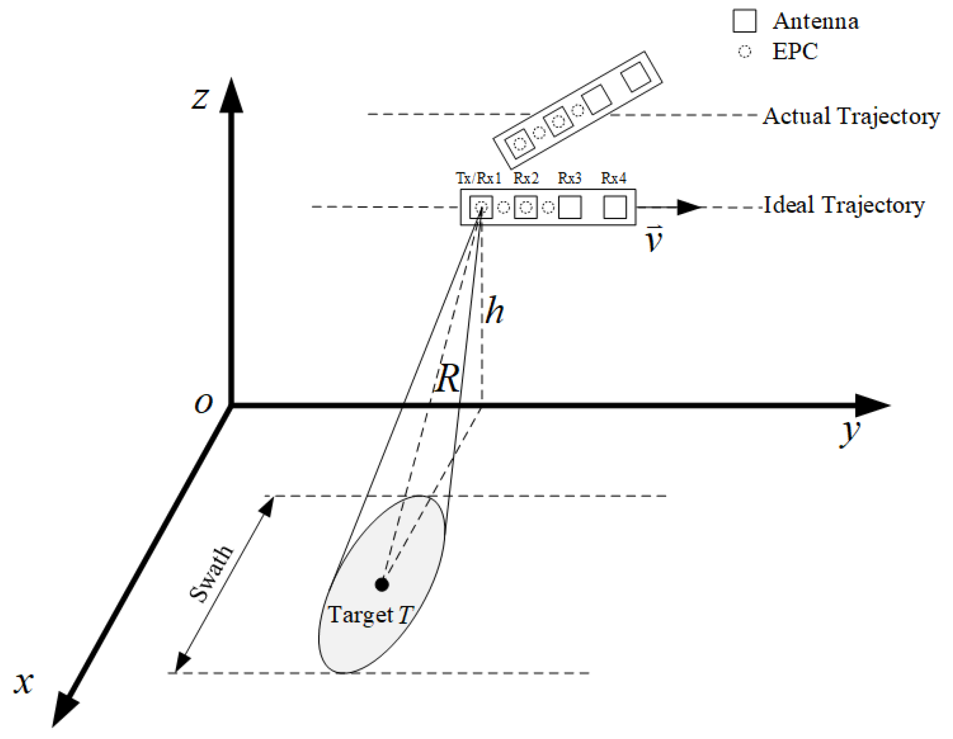
2. Reconstruction Signal with Motion Errors

Azimuth multichannel SAR geometry with motion errors is shown in Figure 1, where the platform traverses along the y-axis, the platform velocity is v, and R is the range between the target and the platform. The SAR system has four channels in azimuth, where the first channel denoted by Tx transmits signals and all the channels denoted by Rx receive signals. Multiple channels are distributed at equal intervals along the azimuth direction with a channel spacing of L. A multichannel SAR system with a separate transmitter and receiver can be equated to a single-channel SAR by compensating for the echo phase [32]. The equivalent phase centers (EPCs) of the equivalent single-channel SAR are situated at the midpoint between the transmitter and receiver as shown by the dashed circle in Figure 1. When the platform is subjected to vibration and turbulence, the platform deflects and rotates during flight, deviating from the desired trajectory.
In general, considering the transmission of a linear frequency modulation signal transmitted by the SAR system, the compressed echo acquired received at EPC is represented as follows:
s ( t , η ) = sinc { B [ t t * ( η ) ] } e j 2 π f c t * ( η )
where t denotes the fast time in range, η represents the azimuth slow time, sinc ( · ) is the sinc function and represents the range envelope, B is the transmitted signal bandwidth, t * represents the time delay dependent on azimuth slow time η and the scatter, and f c denotes the signal frequency.
Let i denote the pulse repetition interval (PRI) index, where i = 1 , 2 , . . . , I . u denotes the channel index where u = 1 , 2 , 3 , 4 . η i , u denotes the non-uniformly slow time at the ith PRI for channel u. The compressed echo at η i , u is represented as s ( t , η i , u ) .
To acquire the unambiguous image of the HRWS SAR, the non-uniformly sampled echo needs to be processed. Using the image-domain reconstruction algorithm [33], the imaging result is computed as
z m = h = 1 H γ h b m , h
where m denotes the pixel index in the discrete imaging scene, h denotes the sub-image index, γ h denotes the reconstruction coefficient for the hth sub-image, and b m , h denotes the mth imaging value of the hth sub-image. The sub-image value b m , h by utilizing the BP algorithm is obtained as follows.
b m , h = b m , u , l , w = i = 1 I s ( t i + l , u , m , η i + l , u ) e j 4 π R i , w , m λ
where l is the interpolation factor. w denotes the channel index in uniform sampling. h denotes a sequence of three variables u, l and w. R i , w , m is the range between EPC at uniformly slow time and the mth pixel, which is written as follows.
R i , w , m = p i , w q m 2
where p i , w denotes the ideal EPCs by uniformly sampling, and q m denotes the position of the mth pixel.
When there are motion errors, the motion errors severely degrade the image quality of the multichannel SAR. SI-MEC can compensate for the motion errors by utilizing one-channel errors [31], and Equation (3) can be rewritten as follows.
b m , h = i = 1 I s ( t i + l , u , m , η i + l , u ) e j 4 π R ˜ i , w , m λ
where
R ˜ i , w , m = p i , w + Δ p i + l , 1 q m 2
Δ p i + l , 1 is the EPC error of channel 1, which is utilized to rectify the motion errors across all channels. When the multiple channels motion errors are inconsistent, the method fails to perform adequate compensation for each individual channel, leading to a degradation of imaging quality.

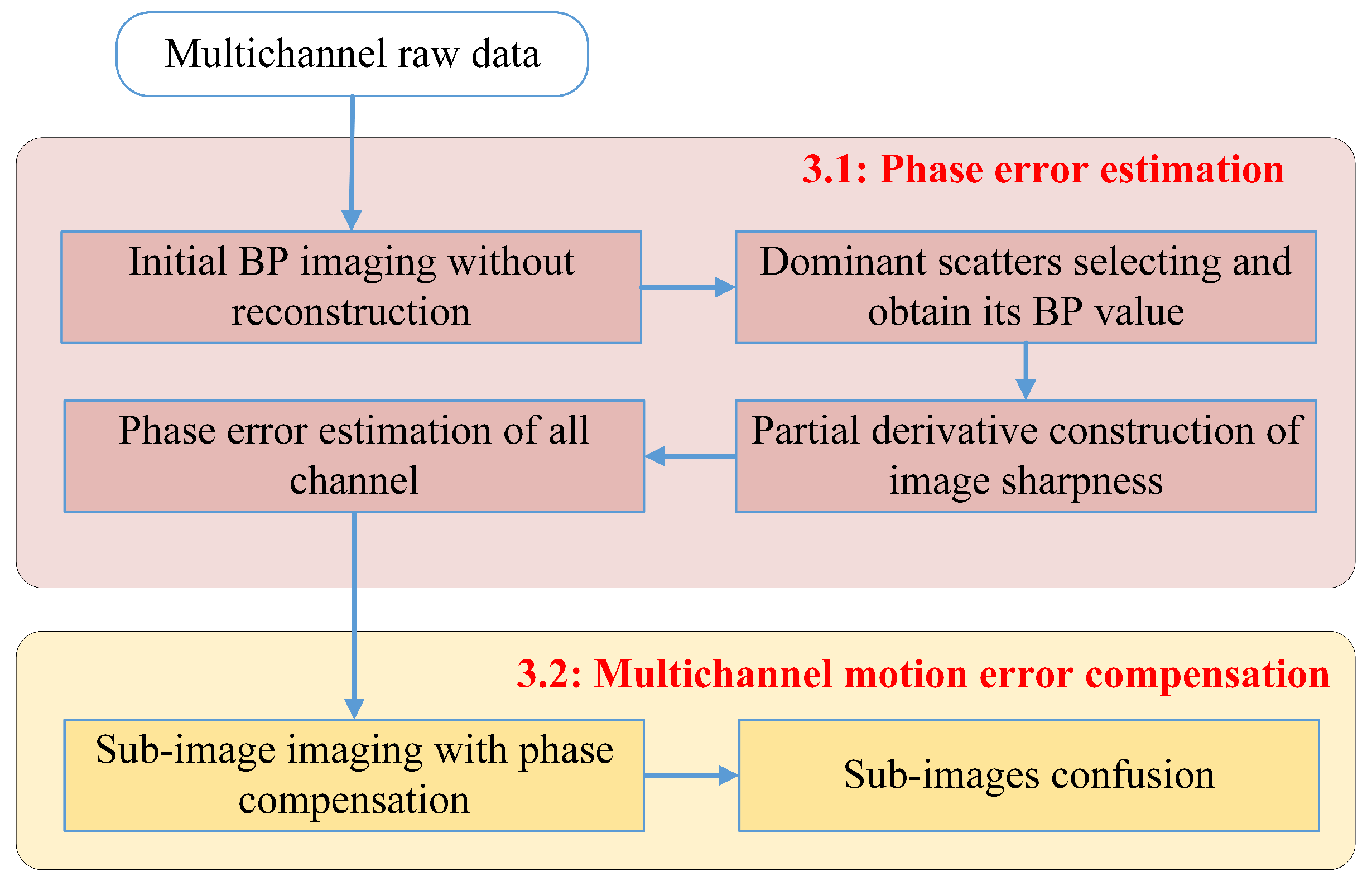
3. Multichannel SAR Motion Compensation Method

To obtain high-quality images, multichannel motion errors need to be compensated. This section first describes the multichannel phase errors estimation method, which utilizes an image quality-based autofocus method to simultaneously estimate the phase errors of multiple channels at each azimuth time. The estimated errors are then utilized for multichannel motion compensation during HRWS SAR imaging.
Figure 2 shows the flowchart for multichannel SAR motion compensation. The method consists of two main stages. First, the SAR imaging process without reconstruction is executed to acquire the initial SAR image, which utilizes the multichannel raw echo data. To improve the estimation efficiency, the dominant scatters in the initial image are selected. The image sharpness of the initial image and partial derivatives are constructed. In order to estimate the phase errors of all channels, the phase errors estimation model via initial image maximum sharpness is derived. Then, the estimated phase errors are utilized to compensate for the motion errors during the HRWS SAR sub-images imaging process to obtain an unambiguous high-quality SAR image. The final image is obtained by weighting the sub-images using the reconstruction coefficients.

3.1. Phase Errors Estimation

Before multichannel motion compensation, the phase errors estimation of all channels in each pulse repetition period is introduced. In order to concurrently estimate the phase errors, we use the image quality-based autofocus method, utilizing the multichannel echo before reconstruction. When the multichannel echo before reconstruction is directly utilized for imaging, the image result suffers from defocusing and ambiguity. Since defocus is caused by motion errors and is independent of ambiguity, motion errors can be estimated according to the image defocus phenomena, i.e., imaging quality before reconstruction. The motion errors estimation process does not require reconstruction of the multichannel echo, thus avoiding the operation of reconstruction in this process.
Autofocus methods based on image quality require the quantification of SAR image quality. Drawing inspiration from the maximum sharpness technique, image sharpness is imployed as the evaluative criterion.
We use the BP algorithm [34] to process the multichannel non-uniformly sampling echo, and the imaging results with motion compensation are given as follows.
B m = u = 1 4 i = 1 I s t i , u , m , η i , u · e j ϕ i , u · e j 4 π R i , u , m λ = u = 1 4 i = 1 I b m , i , u · e j ϕ i , u
where
b m , i , u = s t i , u , m , η i , u · e j 4 π R i , u , m λ
ϕ i , u denotes the phase errors of the uth channel at the ith PRI. The phase errors vector ϕ is denoted as
ϕ = ϕ 1 , 1 , ϕ 1 , 2 , ϕ i , u , , ϕ I , 4
The image sharpness of the mth pixel is obtained as follows [22].
S m = g m 2
where g m = B m B m * denotes the image intensity.
Assume that there are a total of M pixels in the entire imaging region. The maximum BP value of the imaging region can be expressed as
σ = max B m
Select the pixels to satisfy the following equation
B m s e l α · σ
where m s e l is the selected pixel index. α is the coefficient where 0 < α < 1 . Suppose there are M selcted dominant scatters in the observed imaging area. The image sharpness for the dominant scatters is written as
S ϕ = m = 1 M g m ( ϕ ) 2
The closer the phase errors are to the true value, the higher the imaging quality. Let ϕ ^ be the optimal estimation results of the phase errors. High imaging quality is reflected in the image quality evaluation function as a larger image sharpness value. Given the correlation between image sharpness and phase errors, the following optimization model is formulated [35].
ϕ ^ = arg max ϕ S ϕ
where ϕ ^ should satisfy the following equation.
S ϕ ϕ i , u ϕ i , u = ϕ ^ i , u = 0
The gradient of image sharpness S ( ϕ ) can be derived as
S ϕ ϕ i , u = 2 m = 1 M g m g m ϕ ϕ i , u
where
g m ϕ ϕ i , u = B m ϕ B m * ϕ ϕ i , u + B m * ϕ B m ϕ ϕ i , u = 2 Re B m * ϕ B m ϕ ϕ i , u
The gradient of B m ( ϕ ) can be derived as
B m ϕ ϕ i , u = j b i , u , m exp j ϕ i , u
Substituting Equations (17) and (18) into Equation (16), Equation (16) can be expressed as
S ϕ ϕ i , u = 4 m = 1 M g m Re B m * ϕ j b i , u , m exp j ϕ i , u
The gradient vectors consisting of all computed gradient values is written as
S ( ϕ ) = S ϕ 1 , 1 , S ϕ 1 , 2 , , S ϕ I , 4
In order to solve Equation (15), we employ the conjugate gradient method [36]. The procedural steps of the algorithm are delineated as Algorithm 1. The conjugate gradient method is an excellent optimization method, and the optimal estimate can usually be obtained through several iterations [37].
Algorithm 1. Multichannel Phase Estimating via Maximum Sharpness
Inputs: Multichannel SAR echo signal s
Step1: Process multichannel echoes using BP algorithm to obtain preliminary imaging results B m
Step2: Select dominant scatters B m s e l from the preliminary image
Step3: Derive the image sharpness of the selected region S ϕ
Step4: Construct the gradient of the objective function S ϕ ϕ i , u
Step5: Obtain the jth estimated phase by conjugate gradient method
             ϕ j + 1 = ϕ j + β j d j
Step6: Repeat step 5 when
             S ϕ j + 1 S ϕ j 2 S ϕ j 2 < α
Outputs: compensation phase ϕ
MMEC consists of two main parts: one is phase errors estimation and the other is HRWS SAR imaging with motion errors compensation. Their computational complexity is analyzed.
(1) For phase errors estimation: M dominant scatters in the observed imaging region were selected by MMEC. The main operations of the estimation algorithm are the computation of sharpness and gradient. The time complexity of the BP algorithm can be expressed as O N a N x N y , where N a is the number of azimuth samples, and N x and N y are the sizes of the imaging scene. The time complexity for M scatters is O N a M . Let the amount of calculation of the BP algorithm for full-scene pixels be Θ B P , one estimation contains l 1 BP imaging and l 2 iterations. Compared to the phase errors estimation using full scene pixels, the total computation amount of MMEC is approximated as l 1 l 2 M Θ B P N x N y .
(2) For HRWS SAR imaging with motion errors compensation: HRWS SAR imaging mainly consists of γ h times BP imaging, whose amount of calculation is γ h Θ B P , which is the main computation of the sub-image reconstruction-based HRWS SAR imaging algorithm.

3.2. Multichannel Motion Errors Compensation

We used the sub-image reconstruction method to process non-uniform sampling echo for HRWS SAR imaging, which utilizes a BP algorithm to obtain sub-images and performs reconstruction on image fusion. Motion compensation for each channel is implemented during obtaining the sub-image, which is derived as
b m , h = b m , u , l , w = i = 1 I s t i + l , u , m , η i + l , u · e j ϕ ^ i , u · e j 4 π R i , w , m λ
In this equation, the estimated motion errors of each channel in each pulse repetition period are utilized for motion compensation. Finally, the unambiguous imaging result is obtained according to Equation (2).

4. Experiments

In this section, multichannel SAR simulations are conducted to validate the proposed method.

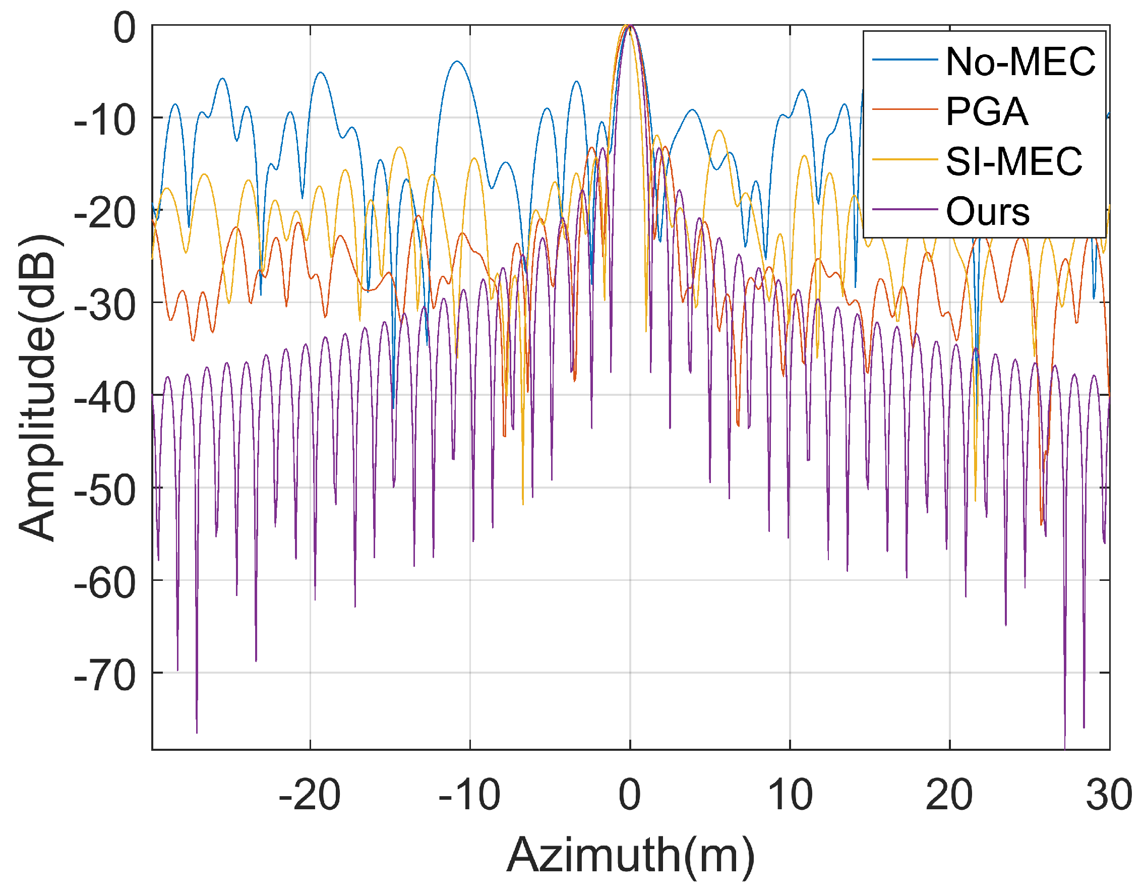
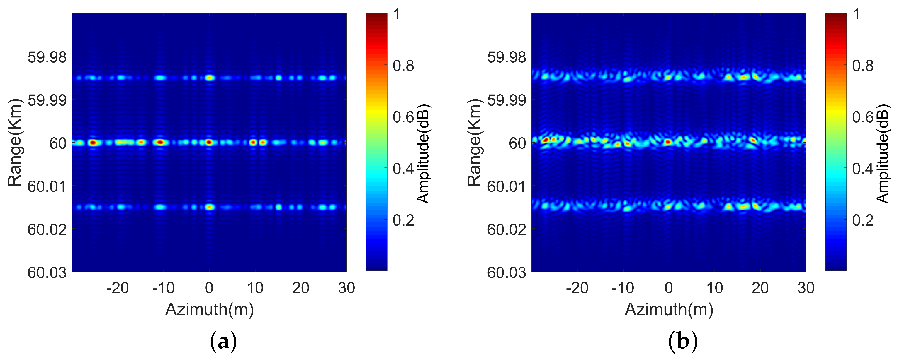
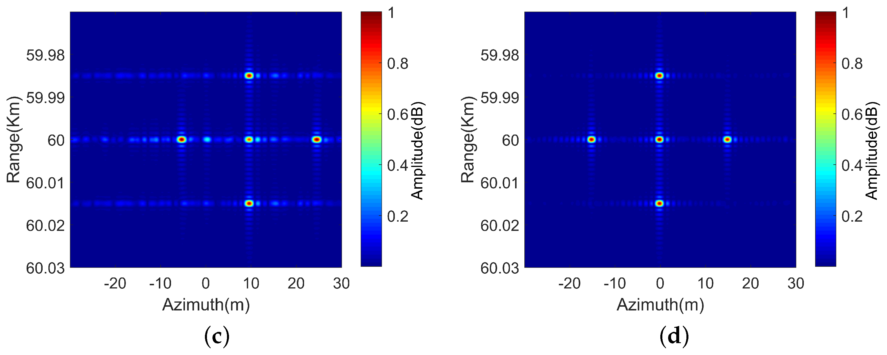
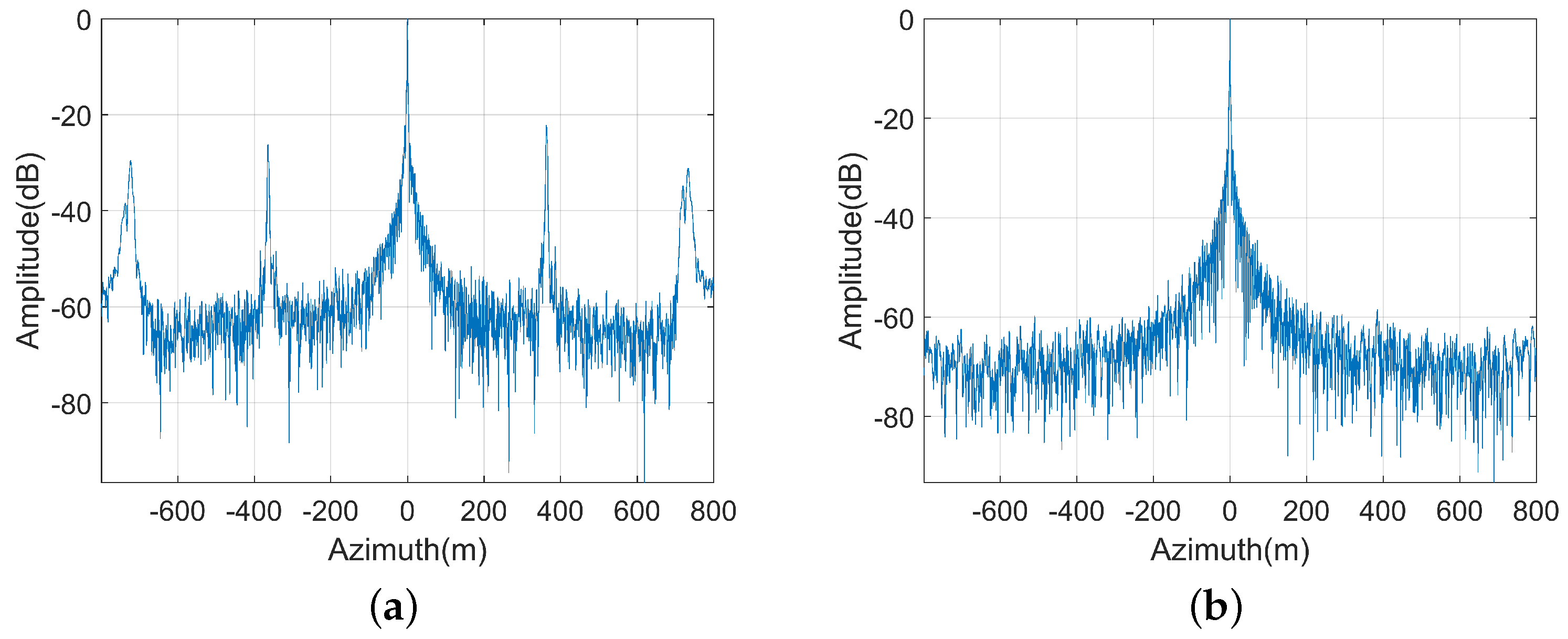
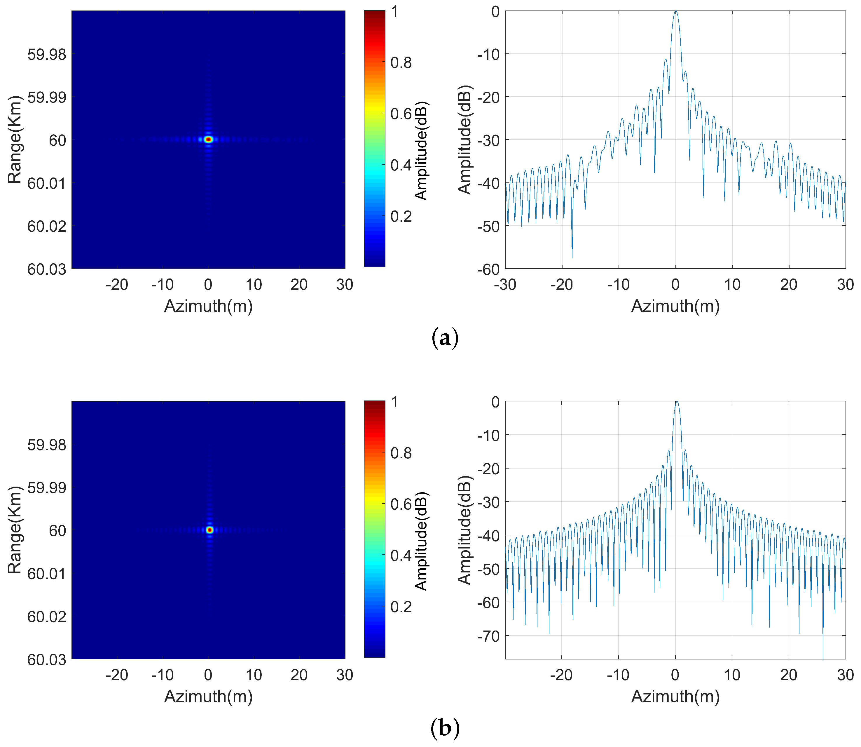
4.1. Point Target Simulation

The simulation parameters for the point target are presented Table 1. Let the coordinate of the point target be [60,0,0] Km. The platform moves uniformly and linearly in the azimuth direction, and we add motion errors in the height direction to each channel in each pulse repetition period, which features random uniform noises between 2 λ and 2 λ .
In order to validate the efficacy of the proposed method, we conducted a comparative analysis with PGA and SI-MEC. Figure 3 is the point target results by using different motion compensation methods. From Figure 3a, we can see that the point target imaging result defocused seriously without motion compensation. In Figure 3b,c, the PGA and SI-MEC can improve the quality of imaging to some extent, but they still suffer from high sidelobes. Obviously, the focusing quality of MMEC performs well compared to the traditional PGA and SI-MEC.
Moreover, we compare the point target results in azimuth for various approaches, as shown in Figure 4. It indicates that the sidelobes of MMEC are significantly lower than those of PGA and SI-MEC.
To further analyze the performances of different methods, Table 2 displays the azimuth peak sidelobe ratio (PSLR) and azimuth integrated sidelobe ratio (ISLR) for the point target. The PSLR and ISLR of MMEC are inferior compared to those of PGA and SI-MEC. The results demonstrate that MMEC significantly enhances the focusing quality.
To further validate the effectiveness of the proposed algorithm for multiple point targets, simulation experiments for five point targets are implemented. The simulation parameters are kept constant, as shown in Table 1. The simulation results for multiple point targets are shown in Figure 5. From the figure, it can be seen that it is difficult for PGA to improve the image quality, and SI-MEC improves the image quality but the sidelobe is high and the position of the point targets is shifted. The proposed method has good imaging results.

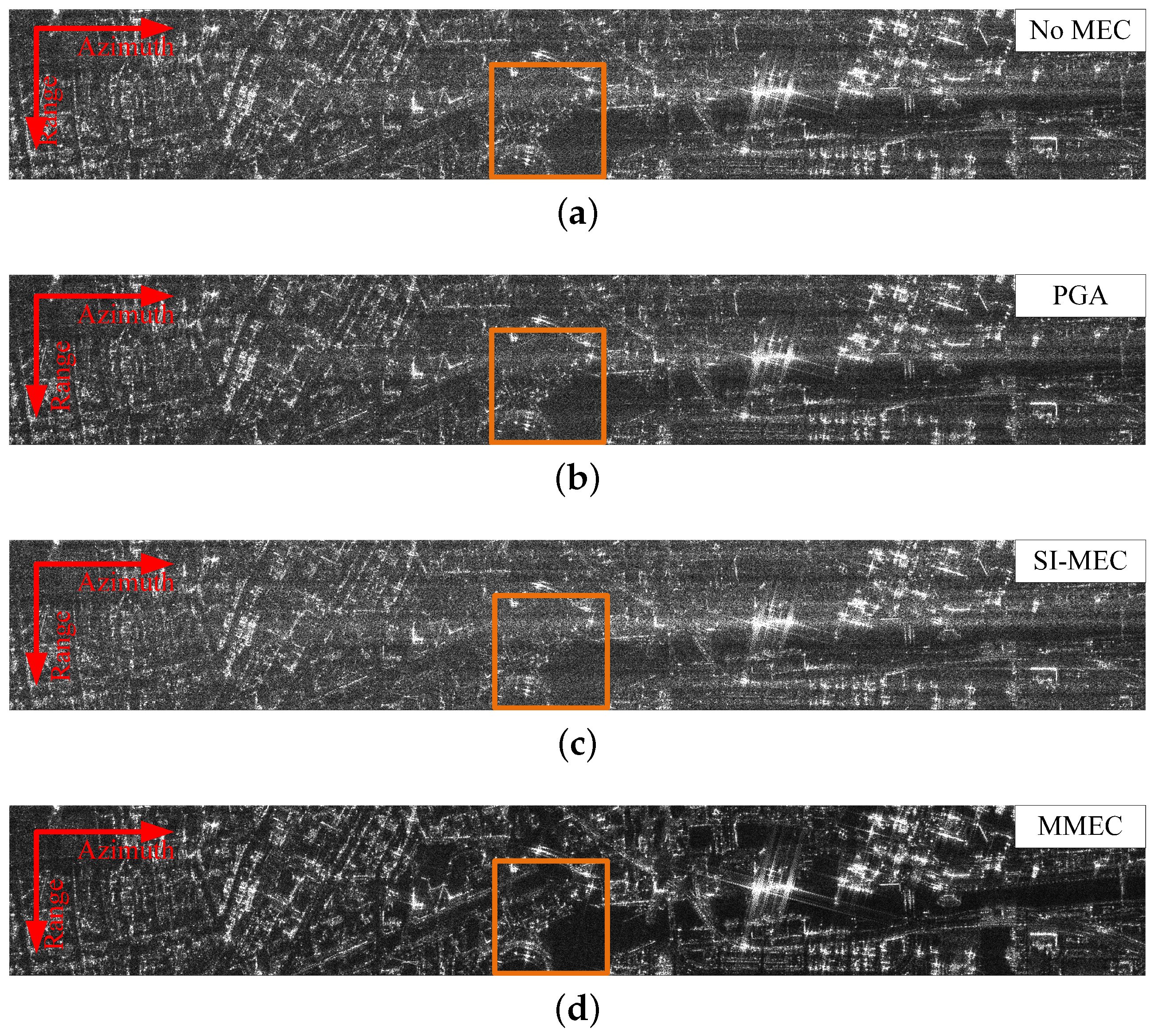
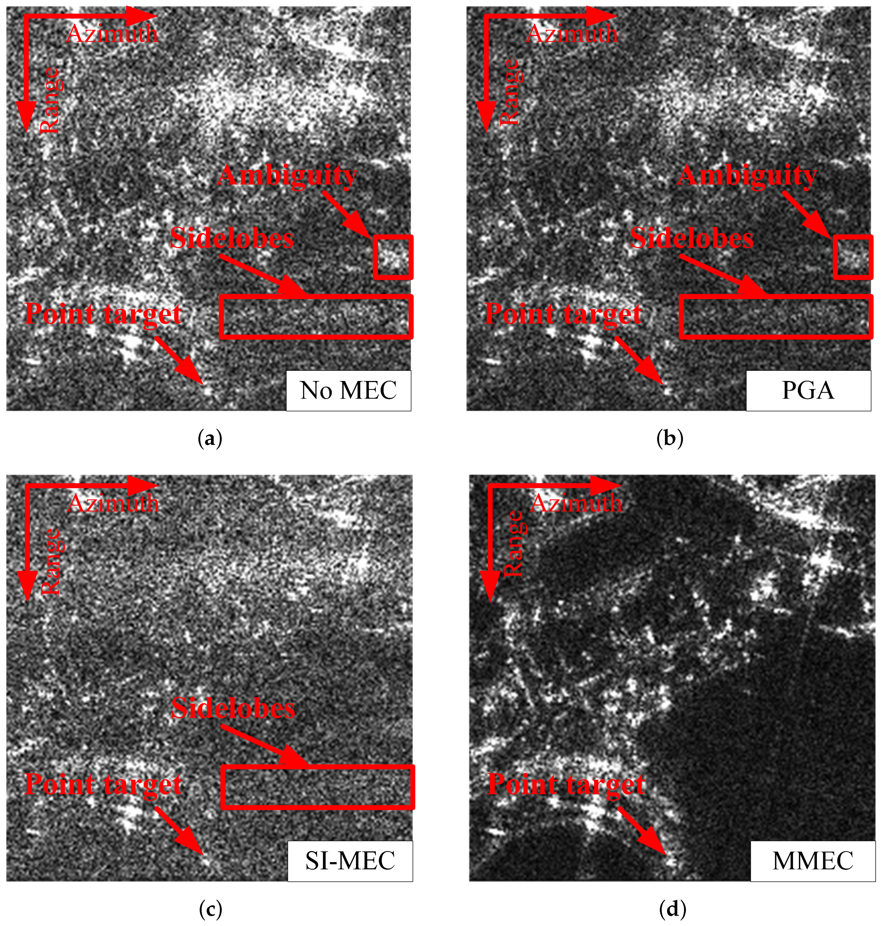
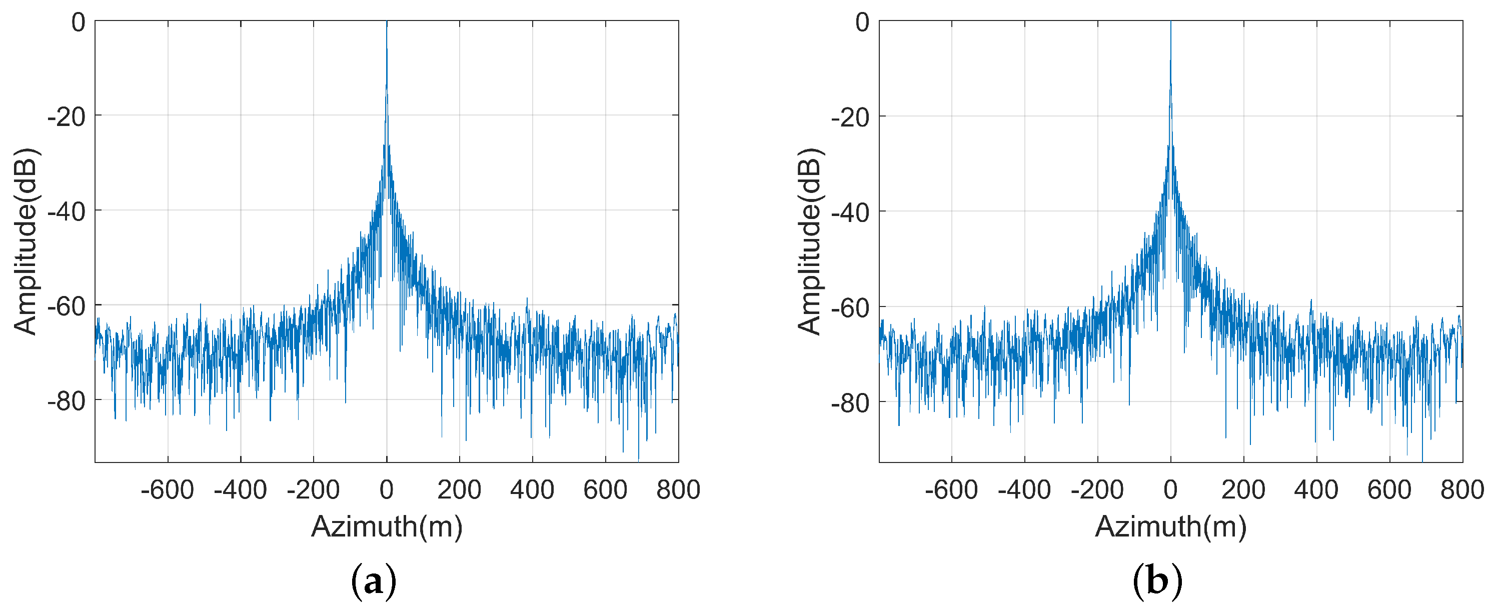
4.2. Complex Scene Simulation

This section uses the imaging result of a complex scene to substantiate the efficacy of MMEC. The system parameters are the same as those of the target simulation experiment as delineated in Table 1. We add motion errors to each channel in each pulse repetition period, whose values range from 0.25 λ to 0.25 λ in the height direction. A real SAR image is utilized to simulate multichannel SAR echo signal. The size of the scene is 300 m in range and 2000 m in azimuth. The image-domain reconstruction (IDR) method is an HRWS SAR imaging algorithm that utilizes interpolation and BP algorithms [33]. Figure 6 presents the performance of the complex scene using IDR without autofocus, PGA, SI-MEC and the proposed method, respectively. Clearly, IDR without autofocus, PGA, and SI-MEC suffer from severe defocus. MMEC is capable of delivering superior focusing quality compared to both the PGA and SI-MEC. It can be found that MMEC is capable of performing effectively even in complex environments.
To evaluate the effectiveness of different methods in complex scenes, two metrics consisting of the image sharpness and entropy are displayed in Table 3. It can be seen that the image entropy of MMEC is inferior to that of PGA and SI-MEC, and the image sharpness is higher than that of PGA and SI-MEC. In terms of image metrics, the proposed method significantly improves the imaging quality.
The magnified images for the full scene are depicted in Figure 7. Figure 8 illustrates the azimuthal imaging result for the point target marked in the magnified image. From the figure, we can see that MMEC exhibits a significantly reduced sidelobe level. This also proves that MMEC has better performance than PGA and SIMEC.

5. Discussion

This section examines the capacity of MMEC to rectify channel phase errors and the effect of the dominant scatterers areas of the proposed method on the performance of motion errors estimation.

5.1. Performance under Channel Phase Errors

Channel phase errors are added to each channel of the multichannel system, and the phase errors for each channel are set as 0°, 10°, 60°, and 20°, respectively. Figure 9a illustrates the azimuthal imaging result for a simulation point target, which only compensates for motion errors. Since the channel phase error is not compensated, there is ambiguity.
Figure 9b shows the azimuthal imaging result by utilizing MMEC, whose sidelobe and ambiguity of the point target are suppressed. MMEC estimates the motion errors of all channels simultaneously and obtains a compensated phase that includes the channel phase errors, thus compensating for both the motion errors and the channel phase errors.
Figure 10 indicates that the sidelobe of the point target imaging result is affected by the channel phase errors. The maximum sidelobe is −11.16 dB in Figure 10a, while the maximum sidelobe is −14.51 dB in Figure 10b. MMEC exhibits a reduced sidelobe level compared to the procedure that does not incorporate channel phase error compensation.
The proposed method requires selecting an area for phase errors estimation, and we have analyzed the imaging performance of selecting different areas. An area of 10 m × 1600 m around the point target is selected for estimating the phase errors, and the imaging result is shown as Figure 11a. If there is ambiguity in the imaging result of the point target, this area contains the ambiguity. For Figure 11b, a region of 100 m × 100 m around the point target is selected to estimate the phase errors, and this region contains only the point target and its sidelobe. It can be seen that selecting different regions has little effect on the imaging quality of point targets.
Figure 12 illustrates the imaging result of the complex scene with channel phase errors. This experiment adds not only the motion error utilized in Figure 6 but also the channel phase error. It is verified that the proposed method can correct the channel phase error. Table 4 shows the quality indicators of complex scene HRWS SAR images. It has good imaging quality by using the proposed method. This shows that MMEC can rectify the channel phase errors while compensating for the motion errors.
Figure 13 illustrates the azimuthal imaging result of a point target marked in Figure 12. It shows that MMEC can effectively improve the imaging quality when there are motion errors and channel errors in multichannel SAR.

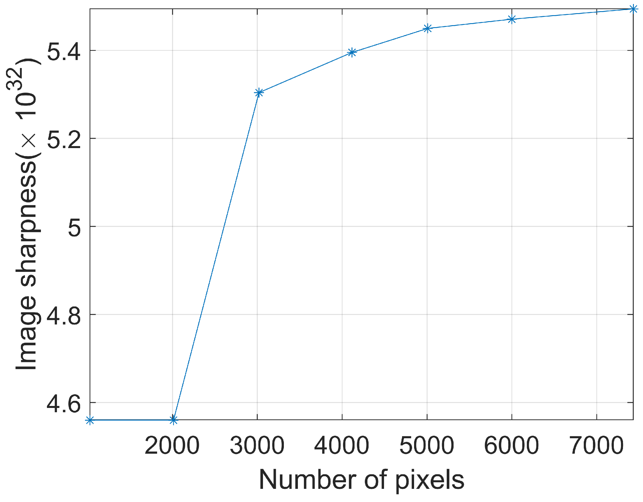
5.2. The Area Selecting for Estimation

The proposed method requires the selection of dominant scatterers of the preliminary imaging results to estimate the phase errors. The effect of selecting various dominant scatterers on the performance of phase errors estimation is analyzed. The proposed method uses the multichannel echo data without reconstruction to generate preliminary imaging results for dominant scatterers selection. Figure 14a shows the preliminary imaging result, which contains motion errors and channel phase errors. Figure 14b is the dominant scatterers selected from the preliminary image. These dominant scatterers are used for phase error estimation in subsequent steps. The dominant scatterers are sparse compared to the pixels of the full scene, which reduces the amount of computation for estimation.
Figure 15 shows the relationship between the number of pixels and the image sharpness of the imaging result. The more pixels there are, the higher the image quality of the imaging result, but the more time is consumed for estimation. When the number of pixels is too small, it will result in failure to compensate for the motion errors. In this experiment, when the number of pixels is less than 2000, the image quality of the imaging result is severely degraded.

6. Conclusions

In this article, we have presented a multichannel SAR motion compensation algorithm based on backprojection reconstruction. First, the SAR imaging process without reconstruction is executed to acquire the initial SAR image. After that, the phase error estimation model via initial image maximum sharpness is derived by using the initial SAR image. Then, the estimated phase errors are utilized to compensate for the motion errors during the HRWS SAR sub-images imaging process to obtain an unambiguous high-quality SAR image. The proposed method can estimate the phase errors of all channels and compensate for the inconsistent motion errors of multiple channels. Compared with PGA and SIMEC, the proposed method can compensate the random phase error well. Since the proposed method compensates for the phase errors during sub-image reconstruction by BP, it can inherit the advantages of dealing with nonlinear trajectories and implementing weighted reconstruction in the image domain. Moreover, the proposed method can correct the channel phase errors while compensating for the motion errors, suppressing azimuth ambiguity when there are channel phase errors. Selecting more dominant scatterers improves imaging quality but suffers a greater computational burden.

Author Contributions

All the authors contributed extensively to the preparation of this manuscript. L.Z. and S.W. conceived the methods and performed the experiments; M.D., J.H. and X.L. provided support for the experiment and offered suggestions on revision; B.W. and S.Z. supervised the research and commented on the manuscript; and L.Z. wrote the paper. All authors have read and agreed to the published version of the manuscript.

Funding

This work was supported in part by the Foundation of ‘National Key Laboratory of Electromagnetic Space Security’, and in part by the National Natural Science Foundation of China under Grant 62271108.

Data Availability Statement

Data sharing is not applicable to this article.

Acknowledgments

We thank anonymous reviewers for their comments toward improving this manuscript.

Conflicts of Interest

The authors declare no conflicts of interest.

References

  1. Jiang, Y.; Sun, B.; Li, J. An Image-Domain Signal Model for Azimuth Multichannel Reconstruction and Its Applications. IEEE Trans. Geosci. Remote Sens. 2023, 61, 1–13. [Google Scholar] [CrossRef]
  2. Wang, X.; Ruan, Y.; Zhang, X. Accuracy Improvement of High-Resolution Wide-Swath Spaceborne Synthetic Aperture Radar Imaging with Low Pule Repetition Frequency. Remote Sens. 2023, 15, 3811. [Google Scholar] [CrossRef]
  3. Xu, Z.; Lu, P.; Cai, Y.; Li, J.; Yang, T.; Wu, Y.; Wang, R. An Efficient Channel Imbalance Estimation Method Based on Subadditivity of Linear Normed Space of Sub-Band Spectrum for Azimuth Multichannel SAR. Remote Sens. 2023, 15, 1561. [Google Scholar] [CrossRef]
  4. Zhang, S.; Xing, M. A Novel Doppler Chirp Rate and Baseline Estimation Approach in the Time Domain Based on Weighted Local Maximum-Likelihood for an MC-HRWS SAR System. IEEE Geosci. Remote Sens. Lett. 2017, 14, 299–303. [Google Scholar] [CrossRef]
  5. Li, B.; Sun, G.C.; Xing, M.; Hu, Y.; Guo, L.; Bao, Z. Clutter suppression via subspace projection for spaceborne HRWS multichannel SAR system. IEEE Geosci. Remote Sens. Lett. 2019, 17, 1538–1542. [Google Scholar] [CrossRef]
  6. Krieger, G.; Gebert, N.; Moreira, A. SAR signal reconstruction from non-uniform displaced phase centre sampling. In Proceedings of the IGARSS 2004. 2004 IEEE International Geoscience and Remote Sensing Symposium, Anchorage, AK, USA, 20–24 September 2004; IEEE: Piscataway, NJ, USA, 2004; Volume 3, pp. 1763–1766. [Google Scholar]
  7. Cai, Y.; Lu, P.; Li, B.; Li, J.; Chen, Y.; Wang, Y.; Nan, Y.; Wang, R.; Wu, Y. An efficient phase error calibration method for azimuth multichannel SAR based on least spectrum difference. IEEE Trans. Geosci. Remote Sens. 2024, 62, 1–13. [Google Scholar] [CrossRef]
  8. Li, N.; Zhang, H.; Zhao, J.; Wu, L.; Guo, Z. An Azimuth Signal-Reconstruction Method Based on Two-Step Projection Technology for Spaceborne Azimuth Multi-Channel High-Resolution and Wide-Swath SAR. Remote Sens. 2021, 13, 4988. [Google Scholar] [CrossRef]
  9. Sikaneta, I.; Cerutti-Maori, D.; Klare, J.; Gierull, C. Comparison of multi-channel high-resolution wide-swath SAR processing methods. In Proceedings of the 2014 IEEE Geoscience and Remote Sensing Symposium, Quebec City, QC, Canada, 13–18 July 2014; IEEE: Piscataway, NJ, USA, 2014; pp. 3834–3837. [Google Scholar]
  10. Tang, J.; Deng, Y.; Wang, R.; Zhao, S.; Li, N.; Wang, W. A weighted backprojection algorithm for azimuth multichannel SAR imaging. IEEE Geosci. Remote Sens. Lett. 2016, 13, 1265–1269. [Google Scholar] [CrossRef]
  11. Guo, J.; Chen, J.; Li, C.; Yang, W. An airborne multi-channel SAR imaging method with motion compensation. In Proceedings of the IGARSS 2019—2019 IEEE International Geoscience and Remote Sensing Symposium, Yokohama, Japan, 28 July–2 August 2019; IEEE: Piscataway, NJ, USA, 2019; pp. 8554–8557. [Google Scholar]
  12. Zhang, T.; Liao, G.; Li, Y.; Gu, T.; Zhang, T.; Liu, Y. A two-stage time-domain autofocus method based on generalized sharpness metrics and AFBP. IEEE Trans. Geosci. Remote Sens. 2021, 60, 1–13. [Google Scholar] [CrossRef]
  13. Thompson, D.G.; Bates, J.S.; Arnold, D.V. Extending the phase gradient autofocus algorithm for low-altitude stripmap mode SAR. In Proceedings of the 1999 IEEE Radar Conference. Radar into the Next Millennium (Cat. No. 99CH36249), Waltham, MA, USA, 22 April 1999; IEEE: Piscataway, NJ, USA, 1999; pp. 36–40. [Google Scholar]
  14. Zhang, L.; Qiao, Z.; Xing, M.d.; Yang, L.; Bao, Z. A robust motion compensation approach for UAV SAR imagery. IEEE Trans. Geosci. Remote Sens. 2012, 50, 3202–3218. [Google Scholar] [CrossRef]
  15. Yang, L.; Xing, M.; Zhang, L.; Sheng, J.; Bao, Z. Entropy-based motion error correction for high-resolution spotlight SAR imagery. IET Radar Sonar Navig. 2012, 6, 627–637. [Google Scholar] [CrossRef]
  16. Potsis, A.; Reigber, A.; Mittermayer, J.; Moreira, A.; Uzunoglou, N. Sub-aperture algorithm for motion compensation improvement in wide-beam SAR data processing. Electron. Lett. 2001, 37, 1–2. [Google Scholar] [CrossRef]
  17. Kennedy, T. Strapdown inertial measurement units for motion compensation for synthetic aperture radars. IEEE Aerosp. Electron. Syst. Mag. 1988, 3, 32–35. [Google Scholar] [CrossRef]
  18. Kim, J.W.; Hwang, I.J.; Jo, H.W.; Kim, G.; Yoo, J.S.; Yu, J.W. Phase error compensation in fourier domain for fast autofocus of spotlight SAR. In Proceedings of the 2017 USNC-URSI Radio Science Meeting (Joint with AP-S Symposium), San Diego, CA, USA, 9–14 July 2017; IEEE: Piscataway, NJ, USA, 2017; pp. 31–32. [Google Scholar]
  19. Kim, J.W.; Kim, Y.D.; Yeo, T.D.; Khang, S.T.; Yu, J.W. Fast Fourier-Domain Optimization Using Hybrid L1−/Lp-Norm for Autofocus in Airborne SAR Imaging. IEEE Trans. Geosci. Remote Sens. 2019, 57, 7934–7954. [Google Scholar] [CrossRef]
  20. Zeng, T.; Wang, R.; Li, F. SAR Image Autofocus Utilizing Minimum-Entropy Criterion. IEEE Geosci. Remote Sens. Lett. 2013, 10, 1552–1556. [Google Scholar] [CrossRef]
  21. Xi, L.; Guosui, L.; Ni, J. Autofocusing of ISAR images based on entropy minimization. IEEE Trans. Aerosp. Electron. Syst. 1999, 35, 1240–1252. [Google Scholar] [CrossRef]
  22. Morrison, R.L.; Do, M.N.; Munson, D.C. SAR image autofocus by sharpness optimization: A theoretical study. IEEE Trans. Image Process. 2007, 16, 2309–2321. [Google Scholar] [CrossRef]
  23. Schulz, T.J. Optimal sharpness function for SAR autofocus. IEEE Signal Process. Lett. 2006, 14, 27–30. [Google Scholar] [CrossRef]
  24. Ash, J.N. An Autofocus Method for Backprojection Imagery in Synthetic Aperture Radar. IEEE Geosci. Remote Sens. Lett. 2012, 9, 104–108. [Google Scholar] [CrossRef]
  25. Wang, J.; Liu, X. SAR minimum-entropy autofocus using an adaptive-order polynomial model. IEEE Geosci. Remote Sens. Lett. 2006, 3, 512–516. [Google Scholar] [CrossRef]
  26. Wang, J.; Liu, X.; Zhou, Z. Minimum-entropy phase adjustment for ISAR. IEE Proc. Radar Sonar Navig. 2004, 151, 203–209. [Google Scholar] [CrossRef]
  27. Kragh, T.J.; Kharbouch, A.A. Monotonic iterative algorithm for minimum-entropy autofocus. In Proceedings of the Adaptive Sensor Array Processing (ASAP) Workshop, Lexington, MA, USA, 6–7 June 2006; Volume 40, pp. 1147–1159. [Google Scholar]
  28. Guo, J.; Chen, J.; Liu, W.; Li, C.; Yang, W. An Improved Airborne Multichannel SAR Imaging Method with Motion Compensation and Range-Variant Channel Mismatch Correction. IEEE J. Sel. Top. Appl. Earth Obs. Remote Sens. 2020, 13, 5414–5423. [Google Scholar] [CrossRef]
  29. Chen, Z.; Zhang, Z.; Qiu, J.; Zhou, Y.; Wang, R. A Novel Motion Compensation Scheme for 2-D Multichannel SAR Systems with Quaternion Posture Calculation. IEEE Trans. Geosci. Remote Sens. 2020, 59, 9350–9360. [Google Scholar] [CrossRef]
  30. Huang, H.; Huang, P.; Liu, X.; Xia, X.G.; Deng, Y.; Fan, H.; Liao, G. A Novel Channel Errors Calibration Algorithm for Multichannel High-Resolution and Wide-Swath SAR Imaging. IEEE Trans. Geosci. Remote Sens. 2021, 60, 1–19. [Google Scholar] [CrossRef]
  31. Zhou, L.; Zhang, X.; Pu, L.; Zhang, T.; Shi, J.; Wei, S. A High-Precision Motion Errors Compensation Method Based on Sub-Image Reconstruction for HRWS SAR Imaging. Remote Sens. 2022, 14, 1033. [Google Scholar] [CrossRef]
  32. Krieger, G.; Gebert, N.; Moreira, A. Unambiguous SAR signal reconstruction from nonuniform displaced phase center sampling. IEEE Geosci. Remote Sens. Lett. 2004, 1, 260–264. [Google Scholar] [CrossRef]
  33. Zhou, L.; Zhang, X.; Wang, Y.; Li, L.; Pu, L.; Shi, J.; Wei, S. Unambiguous Reconstruction for Multichannel Nonuniform Sampling SAR Signal Based on Image Fusion. IEEE Access 2020, 8, 71558–71571. [Google Scholar] [CrossRef]
  34. Jun, S.; Zhang, X.; Yang, J. Principle and methods on bistatic SAR signal processing via time correlation. IEEE Trans. Geosci. Remote Sens. 2008, 46, 3163–3178. [Google Scholar] [CrossRef]
  35. Wei, S.; Zhou, L.; Zhang, X.; Shi, J. Fast back-projection autofocus for linear array SAR 3-D imaging via maximum sharpness. In Proceedings of the 2018 IEEE Radar Conference (RadarConf18), Oklahoma City, OK, USA, 23–27 April 2018. [Google Scholar]
  36. Dai, Y.H.; Yuan, Y. A nonlinear conjugate gradient method with a strong global convergence property. SIAM J. Optim. 1999, 10, 177–182. [Google Scholar] [CrossRef]
  37. Zhou, L.; Zhang, X.; Zhan, X.; Pu, L.; Zhang, T.; Shi, J.; Wei, S. A Novel Sub-Image Local Area Minimum Entropy Reconstruction Method for HRWS SAR Adaptive Unambiguous Imaging. Remote Sens. 2021, 13, 3115. [Google Scholar] [CrossRef]
Figure 1. Four-channel SAR geometry.
Remotesensing 16 03544 g001
Figure 2. Flowchart for multichannel SAR motion compensation.
Remotesensing 16 03544 g002
Figure 3. Point target results utilizing different algorithms. (a) No MEC. (b) PGA. (c) SI-MEC. (d) MMEC (the proposed method).
Remotesensing 16 03544 g003
Figure 4. Point target results in azimuth.
Remotesensing 16 03544 g004
Figure 5. Multiple point targets results utilizing different algorithms. (a) No MEC. (b) PGA. (c) SI-MEC. (d) MMEC (the proposed method).
Remotesensing 16 03544 g005aRemotesensing 16 03544 g005b
Figure 6. Imaging results of complex scene of HRWS SAR system. (a) No MEC. (b) PGA. (c) By SI-MEC. (d) MMEC (the proposed method).
Remotesensing 16 03544 g006
Figure 7. The enlarged imaging results in Figure 6. (a) No MEC. (b) PGA. (c) SI-MEC. (d) MMEC (the proposed method).
Remotesensing 16 03544 g007
Figure 8. The azimuthal imaging result for a point target marked in the enlarged image.
Remotesensing 16 03544 g008
Figure 9. The azimuthal imaging result for a simulation point target. (a) Compensating motion errors only. (b) Using MMEC (the proposed method).
Remotesensing 16 03544 g009
Figure 10. The imaging results. (a) Compensating motion errors only. (b) Using MMEC (the proposed method).
Remotesensing 16 03544 g010
Figure 11. The azimuthal imaging results by selecting diverse areas. (a) Area size 10 m × 1600 m. (b) Area size 100 m × 100 m.
Remotesensing 16 03544 g011
Figure 12. Complex scene HRWS SAR image with channel phase errors. (a) No MEC. (b) PGA. (c) SI-MEC. (d) MMEC (the proposed method).
Remotesensing 16 03544 g012
Figure 13. The azimuthal imaging result for a point target in Figure 12.
Remotesensing 16 03544 g013
Figure 14. Complex scene imaging results without reconstruction. (a) The preliminary imaging result. (b) Dominant scatterers selection.
Remotesensing 16 03544 g014
Figure 15. The relationship between the number of pixels and the image sharpness of the imaging result.
Remotesensing 16 03544 g015
Table 1. Key parameters for simulation.
ParameterValue
Wavelength0.031 m
Bandwidth150 MHz
Sampling frequency210 MHz
Squint angle
PRF700 Hz
Synthetic aperture length987 m
Distance between channel1 m
Number of channels4
Speed1900 m/s
Height20 Km
Table 2. Performance of different methodologies.
MethodNo-MECPGA [18]SI-MEC [31]MMEC
PSLR (dB)−9.15−13.12−11.88−13.26
ISLR (dB)5.988.52−2.42−9.93
Table 3. Quality indicator of complex scene imaging results.
MethodNO MECPGASI-MECMMEC
Image entropy12.2912.2912.3811.77
Image sharpness3.63 × 10 32 3.82 × 10 32 3.0 × 10 32 5.45 × 10 32
Table 4. Quality indicator of complex scene imaging results with channel phase errors.
MethodNO MECPGASI-MECMMEC
Image entropy12.3812.3812.4711.71
Image sharpness3.50 × 10 32 3.67 × 10 32 2.90 × 10 32 5.49 × 10 32
Disclaimer/Publisher’s Note: The statements, opinions and data contained in all publications are solely those of the individual author(s) and contributor(s) and not of MDPI and/or the editor(s). MDPI and/or the editor(s) disclaim responsibility for any injury to people or property resulting from any ideas, methods, instructions or products referred to in the content.

