Abstract
Sea level monitoring is of great significance to the life safety and daily production activities of coastal residents. In recent years, GNSS interferometric reflectometry (GNSS-IR) has gradually developed into a powerful complementary technique for sea level monitoring, with the advantages of wide signal spatial coverage and lower maintenance cost. However, GNSS-IR-retrieved sea level estimates suffer from a prominent error source, referred to as the dynamic height error due to the nonstationary sea level. In this study, the tidal analysis method, least squares method and cubic spline fitting method are used to correct the dynamic height error, and their performances are analyzed. These three methods are applied to multi-system and multi-frequency data from three coastal GNSS stations, MAYG, SC02 and TPW2, for three years, and the retrievals are compared and analyzed with the in situ measurements from co-located tide gauges to explore the applicability of the three methods. The results show that the three correction methods can effectively correct the sea level dynamic height error and improve the accuracy and reliability of the GNSS-IR sea level retrievals. The tidal analysis method shows the best correction performance, with an average reduction of 39.3% (10.7 cm) and 37.6% (6.7 cm) in RMSE at the MAYG and TPW2 stations, respectively. At station SC02, the cubic spline fitting method performs the best, with the RMSE reduced by an average of 39.3% (5.5 cm) after correction. Furthermore, the iterative process of the tidal analysis method is analyzed for the first time. We found the tidal analysis method could significantly remove the outliers and correct the dynamic height error through iterations, generally superior to the other two correction methods. With the dense preliminary GNSS-IR sea level retrievals, the smaller window length of the least squares method can yield more corrected retrievals and better correction performance. The least squares method and cubic spline fitting method, especially the former, are highly dependent on the amount of daily GNSS-IR sea level retrievals, but they are more suitable for dynamic height correction in storm events than the tidal analysis method.
1. Introduction
With global warming, the rise in sea level has become a major challenge for the life and production of residents in coastal areas. To effectively protect the lives and property of residents in these areas, it is crucial to timely monitor and quantify the variation in coastal sea levels. Currently, the most commonly used sea level monitoring methods mainly rely on tide gauges and satellite altimetry. Tide gauges can provide sea level information with the advantages of high precision and high temporal resolution. However, the tide gauge directly contacts with the seawater during its operation and faces many difficulties in installation and maintenance. Furthermore, they are vulnerable to the effects of coastal natural disasters such as storm surges, which can challenge their stability and reliability [1]. Satellite altimetry technology can continuously monitor the sea level of the ocean with a wide coverage. However, satellite altimetry suffers from some limitations such as low spatial resolution, long revisit period, and relatively low precision, which renders it unsuitable for monitoring daily or hourly sea level variations in coastal areas [2].
In recent years, with the continuous development of the Global Navigation Satellite System (GNSS), the signal coverage has been significantly expanded, and related research has been further expanded. Some scholars have found that the reflected GNSS signals contain Earth surface physical information. It has led to the emergence of the GNSS interferometric reflectometry (GNSS-IR) technique, which can retrieve Earth surface parameters through the signal-to-noise ratio (SNR) collected by the ground-based GNSS receivers. This technique has gradually been widely applied in fields such as soil moisture sensing [3,4,5], vegetation detection [6,7,8], snow depth retrieval [9,10,11,12], and sea level monitoring [13,14,15,16,17]. Different from the typical application of GNSS in navigation and positioning, GNSS-IR technology used for sea level monitoring can estimate the vertical distance from the phase center of the GNSS antenna to the instantaneous sea surface by utilizing satellite signals reflected from the sea surface, thus achieving near real-time and continuous monitoring of sea level [18]. GNSS-IR for sea level monitoring has the advantages of wide signal spatial coverage, non-contact measurement and lower maintenance cost [19,20,21]. In 2013, Larson et al. [22,23] successfully retrieved sea level measurements by GNSS-IR from a geodetic GNSS receiver for the first time, with the precision reaching decimeter level. Then, many scholars contributed to the research on GNSS-IR sea level retrieval and developed some methods to correct systemic errors in GNSS-IR sea level retrievals, such as atmospheric refraction correction [24,25] and inter-frequency bias correction [26].
Besides the errors mentioned above, the dynamic height error caused by the sea level variation is the most prominent and dominant error source in GNSS-IR sea level estimates. Various correction methods have been proposed to deal with this error, among which the tidal analysis method [27,28] and the least squares method based on the sliding window [29,30,31] are two representative methods. In 2013, Larson et al. [23] roughly calculated the height derivative based on the initially retrieved height series to obtain the sea level dynamic variation rate, thereby correcting the height error. Löfgren et al. [27] fitted four tidal components to the GNSS-IR sea level retrievals to determine the sea level dynamic variation rate based on the fact that large sea level variations are mainly controlled by the diurnal and semi-diurnal tides. In 2017, Larson et al. [28] further proposed a correction method based on the tidal curve fitting of the original retrieved sea level estimates. In 2015, Roussel et al. [29] first utilized a least squares correction method based on the sliding window to simultaneously solve for sea level variation rate and dynamic sea level. In 2019, Wang et al. [30] proposed a multi-GNSS combined algorithm by integrating multi-frequency data from GPS, GLONASS, Galileo and BDS, significantly improving the precision and temporal resolution of retrieved sea level estimates. In 2022, Wang et al. [31] successfully corrected the dynamic height error of a single SNR arc by combining wavelet analysis and least squares estimation to solve the dynamic variation rate of sea level. In addition to the two main methods mentioned above, Strandberg et al. [14] proposed cubic spline (i.e., B-spline) functions to model the sea level height to obtain more accurate GNSS-IR sea level retrievals.
Currently, many scholars have conducted extensive research on methods for correcting the dynamic height error in GNSS-IR sea level retrievals. Still, there is little literature comparing the correction performances of different methods and their applicability in different station environments. In this study, we apply tidal analysis, least squares, and cubic spline fitting methods to the multi-system and multi-frequency SNR data collected by three coastal GNSS stations over the past three years. Then, the corrected results are compared with the tide gauge measurements, and the applicability of the three methods is analyzed and discussed. In addition, the performance of tidal analysis in an iterative process and the impacts of the window length and step size of the least squares method on the correction results are analyzed for the first time. Lastly, the conclusions are given by summarizing the results and discussion.
2. Materials and Methods
2.1. Sites and Data Description
The three GNSS stations (i.e., MAYG, SC02, and TPW2) used in this study are all located in coastal areas with an open view, suitable for sea level monitoring with GNSS-IR. Figure 1 illustrates the geographic locations of the three GNSS stations. Table 1 summarizes the geographic and instrumental information of each station. Table 2 lists the systems and frequency bands used in the experiment.
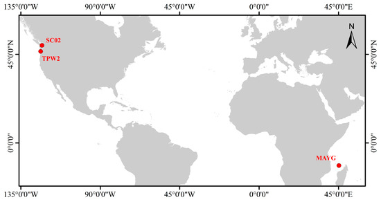
Figure 1.
The geographic locations of the GNSS stations MAYG, SC02 and TPW2.

Table 1.
Information on MAYG, SC02, and TPW2 stations.

Table 2.
Information on the systems and frequencies used in the experiment.
The MAYG station is located on the island of Mayotte in the northwest Indian Ocean, which is officially part of France. MAYG station is operated by Institut Géographique National (IGN) and Centre National d’Etudes Spatiales (CNES). About 2 m away from the station, a tide gauge called Dzaoudzi measures sea level at an interval of 1 min. The tide gauge measurements were reported to have a precision of 1–3 cm [32,33], and they are usually regarded as the references to validate the GNSS-IR sea level retrievals in previous studies [21,28]. We used the GPS toolbox developed by Roesler and Larson [32] and checked the surrounding environment of the MAYG station to determine the azimuth and elevation ranges for GNSS-IR experiments. The azimuth range and elevation range at MAYG are [−30° 180°] and [5° 20°], respectively. Figure 2 shows the surrounding environment of the GNSS station MAYG and tide gauge Dzaoudzi as well as the first Fresnel reflection zone (i.e., sensing zone) of the GNSS-IR from the GPS L1 frequency band at MAYG. We collected the SNR data from the MAYG station from 2018 to 2020 to retrieve sea levels using GNSS-IR.
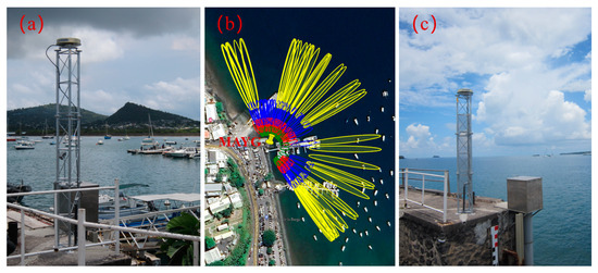
Figure 2.
(a) The surrounding environment of the GNSS station MAYG (https://network.igs.org/ accessed on 25 March 2024); (b) the first Fresnel reflection zone from GPS L1 at MAYG with yellow, blue, red, and green ellipses representing the sensing zones for elevation angles of 5°, 10°, 15°, and 20°, respectively; (c) the surrounding environment of the tide gauge Dzaoudzi (https://www.sonel.org/spip.php?page=maregraphe&idStation=1903 accessed on 25 March 2024).
GNSS station SC02 is located at Friday Harbor on the west coast of the United States, and it is operated by the EarthScope Plate Boundary Observatory (PBO). A tide gauge is situated about 300 m away from the station and provides sea level measurements at a 6-min sampling interval. An elevation angle mask of [5° 13°] and an azimuth angle mask of [50° 240°] are determined for this station. The 3-year-long SNR data from 2020 to 2022 are used for the GNSS-IR experiments. It should be noted that the SC02 station is unable to receive the BDS signals. Figure 3 shows the surrounding environment of the GNSS station SC02 and tide gauge Friday Harbor as well as the first Fresnel reflection zone from the GPS L1 frequency band of the GNSS-IR at SC02.
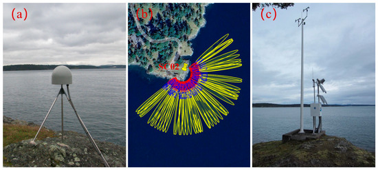
Figure 3.
(a) The surrounding environment of the GNSS station SC02 (https://www.unavco.org/instrumentation/networks/status/nota/photos/sc02 accessed on 25 March 2024); (b) the first Fresnel reflection zone from GPS L1 at SC02 with yellow, blue, red, and green ellipses representing the sensing zones for elevation angles of 5°, 10°, 15°, and 20°, respectively; (c) the surrounding environment of the tide gauge Friday Harbor (https://tidesandcurrents.noaa.gov/stationphotos.html?id=9449880 accessed on 25 March 2024).
GNSS station TPW2 is located at Astoria on the west coast of the United States. A tide gauge Astoria is 2 m away from the station TPW2 and records sea levels at 1-minute intervals. It is also operated by the PBO. At this station, the mask of elevation angle is [5° 15°], and the azimuth angle mask is [170° 250°]. The SNR data recorded by TPW2 from 2020 to 2022 are processed and analyzed. Figure 4 shows the surrounding environment of the GNSS station TPW2 and tide gauge Astoria as well as the first Fresnel reflection zone from the GPS L1 frequency band of the GNSS-IR at TPW2.
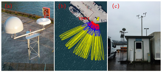
Figure 4.
(a) The surrounding environment of the GNSS station TPW2 (https://www.unavco.org/instrumentation/networks/status/nota/photos/tpw2 accessed on 25 March 2024); (b) the first Fresnel reflection zone from GPS L1 at TPW2 with yellow, blue, red, and green ellipses representing the sensing zones for elevation angles of 5°, 10°, 15°, and 20°, respectively; (c) the surrounding environment of the tide gauge Astoria (https://tidesandcurrents.noaa.gov/stationphotos.html?id=9439040 accessed on 25 March 2024).
2.2. Principles of GNSS-IR for Sea Level Retrieving
In addition to direct signals from satellites, the GNSS antenna also receives the signals reflected by the surrounding reflector, such as the ground and water surface. The reflected signals interfere with direct signals in the receiver and are quantified as the SNR. This interference is known as the multipath effect [33], which is the foundation of the GNSS-IR. By analyzing the SNR at a low elevation angle over the sea area, the oscillation information can be obtained, and thus the sea level can be retrieved. Figure 5 shows the geometry of GNSS-IR sea level retrieval.
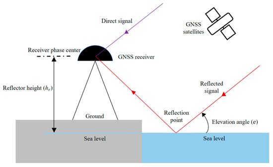
Figure 5.
Geometry of GNSS-IR sea level retrieval.
Since the trend in SNR mainly comes from the direct signal, a low-order polynomial fitting is usually used to remove it. The detrended SNR after removing the trend term can be expressed as [3]:
where is the amplitude (unit: volts/volts) and is the phase shift (unit: degrees), is the signal wavelength (unit: m), is the satellite elevation angle (unit: degrees), and is the reflector height (unit: m) denoting the vertical distance from the phase center of the GNSS receiver antenna to the instantaneous sea surface. The detrended SNR after trend term removal is a cosine function, and the sea level is related to its frequency. The static reflector height is
where is the oscillation frequency of the detrended SNR. Since the Lomb–Scargle Periodogram (LSP) analysis is capable of handling unevenly sampled data and overcoming the effects of spurious signals, missing signals and other problems, it is used to determine the dominant frequency [34]. Then, the static reflector height can be obtained by Equation (2). The number of retrievals depends on the satellite tracks.
As the GNSS signal is affected by the atmosphere along its propagation path, it would introduce a bias in the elevation angle in SNR. The bias would be manifested at a low elevation angle. The atmospheric refraction correction model is used to determine the correction for the elevation angle [35,36].
During the LSP analysis process, quality control is necessary. Generally, retrieval values with a peak-to-noise ratio greater than 3 are selected to ensure the significance and rationality of the peak. The peak-to-noise ratio is the ratio of the spectral peak power to the spectral noise power, where the spectral noise power is the average spectral power of each spectral point, excluding the peak [30]. In addition, it is difficult to avoid the presence of outliers in the retrieved series, and it is necessary to control the range of according to the tidal range of the sea level.
In the reflector height retrieval through Equation (1), it is generally assumed that the sea level is static. However, the sea level is nonstationary, causing the dynamic height error in retrieved reflector height. Larson et al. [23] found the dynamic height error in GNSS-IR sea level retrievals and assumed that it is related to the rate of sea level and the rate of satellite elevation angle , which can be expressed as
where is the static reflector height and is the dynamic reflector height. Correcting the dynamic height error in sea level retrievals is a crucial step towards enhancing the reliability of GNSS-IR sea level monitoring.
2.3. Tidal Analysis Correction Method
Tidal analysis mainly relies on the fact that the sea level changes are dominated by the periodic tide components, which can be expressed as follows [37]:
where is the static reflector height; is the reference reflector height; represents the number of tidal components; is the amplitude of the tidal component; is the period of the tidal component; and is the initial phase of the tidal component.
Sea level variations are mainly dominated by diurnal and semi-diurnal tides. Therefore, we only consider the main driving forces affecting sea level changes, which are four diurnal tides (O1, K1, P1, Q1) and four semi-diurnal tides (M2, S2, N2, K2) (see Table 3). For the tidal analysis (i.e., Equation (4)), except for the known periods for the eight tidal components, the eight amplitude parameters and eight phase parameters as well as the are unknown parameters to be determined. By fitting the time series of to Equation (4), we can solve for the above 17 parameters in total. With the determined parameters, the fitting reflector heights with tidal analysis (i.e., Equation (4)) at the observation time of the GNSS-IR-derived reflector heights are obtained. Then, taking the derivative of Equation (4) with determined parameters, we can obtain the rate of and further obtain the dynamic reflector height through Equation (3). Then, the dynamic reflector height is compared to the fitting reflector height with tidal analysis, and the outliers are detected by using three times the standard deviation as the threshold. If outliers exist, they are removed, and the above steps are repeated iteratively until there are no outliers detected in the retrieved reflector height series. Larson et al. [23,28] used an iterative method to solve the sea level dynamic height error through tidal analysis but did not mention the specific iterative process, and the performance in the iterative process has not been presented. The tidal analysis method used in this study can weaken the negative impact of outliers in the sea level retrieval series on dynamic height error correction through an iterative process. The flowchart of tidal analysis for dynamic height error correction in GNSS-IR sea level retrievals is illustrated in Figure 6.

Table 3.
Detailed information on the eight major tide components.
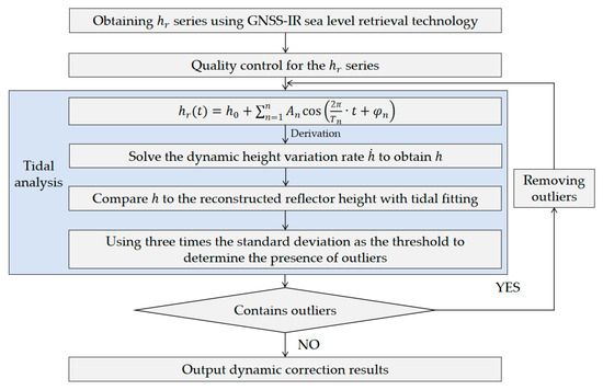
Figure 6.
Flowchart of the correction method for dynamic height error based on tidal analysis in GNSS-IR sea level retrievals.
2.4. Least Squares Correction Method Based on Sliding Window
Roussel et al. [29] first introduced the least squares method for dynamic height error correction in GNSS-IR sea level retrievals. This method commonly applies a temporal window to the time series of static vertical reflection height , and solves dynamic reflector height and height rate using the least squares method window by window as
where . The weights of all retrieved reflector heights within the window are defined as 1, with the weight matrix being the identity matrix. Applied with least squares, the parameters can be estimated as follows:
In the least squares method, the window length is crucial. If the window is too short, the number of retrievals within the window will be insufficient to perform reliable estimation. However, if the window is too long, it may not accurately reflect the temporal sea level variation. The window length is empirically set to 4 h with a moving step of 0.5 h. The empirical window length and moving step are applicable to most GNSS stations with various daily GNSS-IR sea level retrievals. The maximum sea level change within 4 h at three GNSS stations is approximately 2.5 m.
2.5. Cubic Spline Fitting Correction Method
Spline functions can effectively model sea level height [14]. The core idea of the cubic spline fitting method is to smoothly interpolate a given time series of GNSS-IR sea level retrievals by constructing a segmented cubic polynomial function. These polynomials are used to ensure that the interpolation curve not only passes through the retrieval points but also maintains continuity in the derivatives at these points, thereby achieving smooth curve transitions. On each subinterval , the function can be expressed as
where are the parameters to be solved on adjacent intervals and . The two cubic polynomials and need to satisfy the continuity of the zeroth, first, and second derivatives at the common node . In this study, cubic spline fitting was performed with a 3-hour interval to solve for the sea level dynamic variation rate. The outliers are detected using three times the standard deviation as the threshold, and then they are removed from the original GNSS-IR sea level retrievals.
3. Results
3.1. Preliminary GNSS-IR Sea Level Retrievals
Applying the GNSS-IR method described in Section 2.2 to the SNR data collected by the three GNSS stations, we obtained the preliminary time series of the sea level noised by dynamic height error. For simplicity and clarity, Figure 7 only shows the differences between GNSS-IR sea level retrievals and tide gauge measurements for an arbitrary 30 days as well as the tide gauge measurements. The 30-day periods for MAYG, SC02, and TPW2 are from 27 September to 26 October 2020, from 1 January to 30 January 2022, and from 2 December to 31 December 2022, respectively. As can be seen from Figure 7, the differences between GNSS-IR-retrieved sea levels and tide gauge measurements at different systems and frequency bands are small, indicating that the GNSS-IR can effectively monitor the variation in sea level. However, a few large difference values especially at MAYG indicate outliers in the preliminary GNSS-IR retrieval series. The tidal ranges indicated by GNSS-IR sea level estimates from MAYG, SC02 and TPW2 are about 4.4 m, 4.5 m and 4.0 m, respectively, basically consistent with that estimated by the tide gauges. The small differences and similar tidal ranges demonstrates the effectiveness of GNSS-IR sea level monitoring.
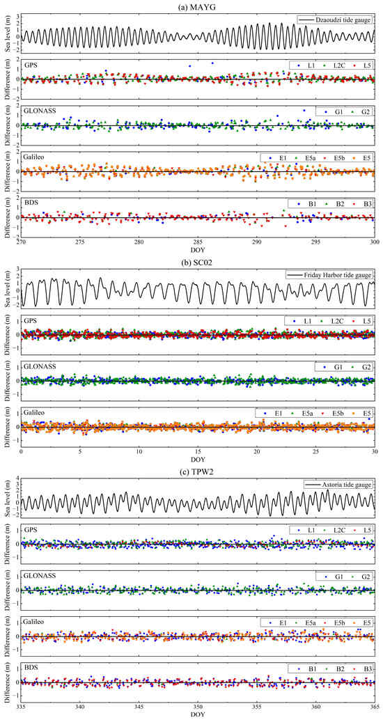
Figure 7.
Time series of the differences between GNSS-IR-retrieved sea levels at three GNSS stations and corresponding tide gauge measurements: (a) the differences between GNSS-IR-retrieved sea levels at MAYG and Dzaoudzi tide gauge measurements from DOY 271 (27 September) to 300 (26 October) in 2020; (b) the differences between GNSS-IR-retrieved sea levels at SC02 and Friday tide gauge measurements from DOY 1 (1 January) to 30 (30 January) in 2022; (c) the differences between GNSS-IR-retrieved sea levels at TPW2 and Astoria tide gauge measurements from DOY 336 (2 December) to 365 (31 December) in 2022.
Due to differences in satellite orbits, the number of sea level estimates obtained through each system and frequency band also varies. Taking the MAYG station as an example, we can see that the number of GNSS-IR-retrieved sea level estimates by the other three systems in each frequency band is significantly larger than that retrieved by the BDS system. This is mainly attributed to the fact that the satellite coverage of the BDS system in the region is relatively sparse, resulting in fewer available satellites and thus affecting the number of retrievals (Figure A1). We compared the preliminary GNSS-IR sea level retrievals to the records from co-located tide gauges. The comparison shows that the average root mean square error (RMSE) of all systems and frequencies at MAYG is 27.2 cm, while the RMSEs at SC02 and TPW2 are 14.0 cm and 17.8 cm, respectively. The results imply the existence of significant error in the preliminary GNSS-IR sea level retrievals.
3.2. Performance of Dynamic Height Error Correction
We corrected the dynamic height error in the GNSS-IR sea level retrievals with different methods described in Section 2. Then, we compared the corrected GNSS-IR sea level retrievals to the tide gauge measurements and obtained the precision indices. The retrieval precisions of all systems and frequency bands at three stations are determined accordingly.
Table 4 shows the precision statistics for the MAYG station. The RMSE of each system and frequency band has been significantly reduced with dynamic height error correction by all three methods, indicating a precision improvement in the GNSS-IR-retrieved sea level. Among the three methods, the tidal analysis method performs best with an average RMSE of 16.5 cm, followed by the least squares method (RMSE = 19. 7 cm), while the cubic spline fitting performs worst with an average RMSE of 21.4 cm. Compared to the uncorrected GNSS-IR sea level retrievals, the precisions are improved by 39.3% (10.7 cm), 27.6% (7.5 cm) and 21.3% (5.8 cm) for tidal analysis, least squares and cubic spline fitting methods, respectively.

Table 4.
Statistics of the number of sea level retrievals and RMSE with and without dynamic height error correction at MAYG station.
In terms of frequency, the RMSE of the GLONASS G1 corrected by the tidal analysis method is the smallest, which is only 12.9 cm. Compared to the RMSE of 27.4 cm without correction, the precision is improved by 52.9%. The RMSE of the Galileo E1 corrected with cubic spline fitting is the largest (25.9 cm), indicating only 5.4% improvements in precision. It should be noted that the relatively fewer retrievals in the BDS B1 (0.7 retrieval per day) and BDS B2 (1.3 retrievals per day) frequency bands are insufficient for the least squares estimation in the sliding window. Thus, the least squares method cannot be applied to the dynamic height error corrections in GNSS-IR sea level retrievals at these two frequencies. Figure 8 presents scatter plots of the GNSS-IR-retrieved sea levels versus in situ sea levels at MAYG for partial frequencies. The scatter plots for other frequencies are presented in Figure A2. It can be seen that the corrected GNSS-IR seal level retrievals agree well with the tide gauge measurements, with correlation coefficients exceeding 96%.
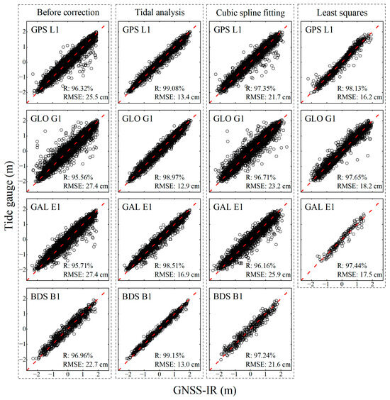
Figure 8.
Scatter plots of GNSS-IR-retrieved sea levels with and without dynamic height error corrections for GPS L1, GLONASS G1, Galileo E1, and BDS B1 at MAYG versus tide gauge measurements. The 1:1 diagonal in each plot is shown as a red dashed line.
Table 5 shows the precision statistics of the GNSS-IR sea level retrievals at SC02 station. It can be seen that the RMSE of the uncorrected GNSS-IR sea level retrievals ranges from 11.7 cm at GLONASS G1 to 15.3 cm at Galileo E5a. As for the GNSS-IR sea level retrievals corrected with the tidal analysis method, the average RMSE of all frequencies is 9.3 cm, indicating 33.6% (4.7 cm) precision improvement over uncorrected GNSS-IR sea level retrievals. The RMSEs of GPS L1 and GPS L2C are 10.0 cm and 10.1 cm, respectively, which are larger by about 1 cm than that of other frequencies. GPS L5 and Galileo E5 perform the best with an RMSE of only 8.9 cm, indicating precision improvements by 34.56% and 39.04%, respectively. As for the GNSS-IR sea level retrievals corrected with the least squares method, except for the GPS L2C, Galileo E5a and Galileo E5b with the RMSEs slightly lower than that of the tidal analysis method by 1~2 mm, the precisions of the other six frequencies are significantly worse than the tidal analysis method, and the average RMSE (9.9 cm) decreases by 29.3% (4.1 cm) compared to that of the uncorrected GNSS-IR measurements. As for the cubic spline fitting method, it performs best among all three methods. The average RMSE is only 8.5 cm, indicating 39.2% (5.5 cm) precision improvement over corrected GNSS-IR measurements. Specifically, the RMSE of Galileo E5 with the cubic spline fitting method is only 7.5 cm, which is the highest precision among all corrected GNSS-IR measurements. Figure 9 presents scatter plots of the GNSS-IR-retrieved sea levels versus in situ sea levels at SC02 for partial frequencies. The scatter plots for other frequencies are presented in Figure A3. As can be seen in Figure 9 and Figure A3, the correlation coefficient between GNSS-IR-retrieved sea levels for each frequency and tide gauge measurements is about 99%. From Figure 9 and Figure A3, it can be seen that there are a few outliers at GPS L1, GPS L2C, and GPS E5a frequencies that are not visible before the correction using the least squares method. This is partly explained by the unstable solution of the least squares for some windows with few retrievals or outliers. Another possible reason is the failure of the least squares method with linear equation when the sea level undergoes drastic nonlinear changes in low tides or high tides. Thus, the estimated sea level significantly deviates from the actual sea level. However, the RMSE reductions after correction indicate the overall effectiveness of the least squares method.

Table 5.
Statistics of the number of sea level retrievals and RMSE with and without dynamic height error correction at SC02 station.
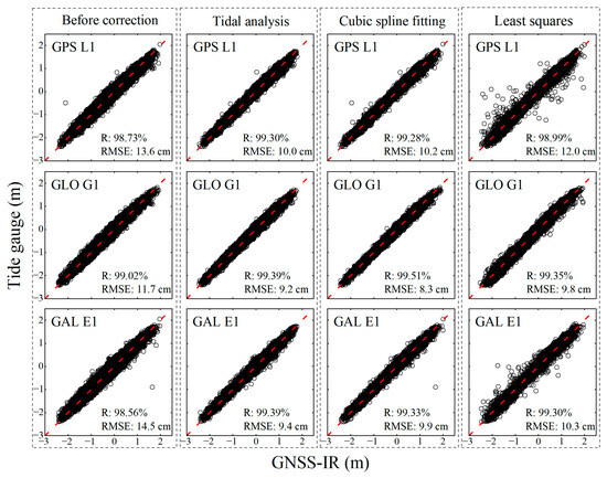
Figure 9.
Scatter plots of GNSS-IR-retrieved sea levels with and without dynamic height error correction for GPS L1, GLONASS G1, and Galileo E1 at SC02 versus tide gauge measurements. The 1:1 diagonal in each plot is shown as a red dashed line.
Table 6 shows the precision statistics of the TPW2 station. It can be seen that the tidal analysis method performs better than the other two methods. The average RMSE of the GNSS-IR sea level measurements corrected by tidal analysis is 11.1 cm, while the average RMSE is 15.0 cm and 14.2 cm for the least squares and cubic spline fitting methods, respectively. Compared to the uncorrected GNSS-IR sea level retrievals, the average RMSE reductions are 37.6% (6.7 cm), 15.7% (2.8 cm), and 25.4% (4.6 cm) for the tidal analysis, least squares, and cubic spline fitting methods, respectively. For individual system and frequency, the RMSE of the tidal analysis method is 1–6 cm smaller than the result of the least squares and cubic spline fitting methods. In terms of frequency, the GPS L5 frequency band performs best with an RMSE of 8.5 cm, indicating a precision improvement of 6.6 cm (42.86%) compared to the precision (RMSE = 15.1 cm) without dynamic height error correction. In contrast, the GLONASS G2 frequency band has the largest RMSE of 14.0 cm, indicating a precision improvement by 2.7 cm (16.17%) compared to the precision (RMSE = 16.7 cm) without correction. Similarly to the results at MAYG station, the relatively fewer retrievals at the GPS L5 (2.3 retrievals per day), Galileo E5a (0.9 retrieval per day) and BDS B2 (1.4 retrievals per day) frequencies are insufficient for the least squares correction. This is the major limitation of the least squares method, which needs dense retrievals for reliable estimation. Figure 10 presents scatter plots of the GNSS-IR-retrieved sea levels versus in situ sea levels at TPW2 for partial frequencies. The scatter plots for other frequencies are presented in Figure A4. It can be seen that the corrected GNSS-IR sea level retrievals agree well with the tide gauge measurements, with correlation coefficients exceeding 98%. Figure 10 and Figure A4 also show some outliers that are not visible before the correction using the least squares method. These outliers also can be associated with the unstable estimation of the least squares method with linear equation under some specific situations such as low tides and high tides.

Table 6.
Statistics of the number of sea level retrievals and RMSE with and without dynamic height error correction at TPW2 station.
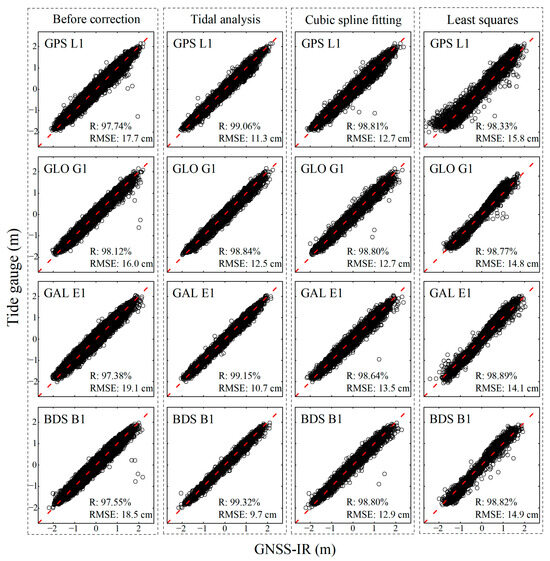
Figure 10.
Scatter plots of GNSS-IR-retrieved sea levels with and without dynamic height error correction for GPS L1, GLONASS G1, Galileo E1, and BDS B1 at TPW2 versus tide gauge measurements. The 1:1 diagonal in each plot is shown as a red dashed line.
Figure 11 shows the comparisons of the RMSE of GNSS-IR-retrieved sea levels with and without the dynamic height error correction for each system and frequency band at the three stations. As can be seen, the tidal analysis method performs better at MAYG and TPW2 stations, followed by the cubic spline fitting method and least squares method. At the SC02 station with the densest retrievals, the cubic spline fitting method is slightly better than the other two methods. The least squares method failed to correct the dynamic height error at two frequencies at MAYG and three frequencies at TPW2, indicating its high dependence on the number of daily GNSS-IR sea level retrievals. Although the correction effects of the retrieved sea levels vary by different systems and frequencies, the precisions are improved significantly after the dynamic height error correction by all three methods, indicating the effectiveness of the correction methods.
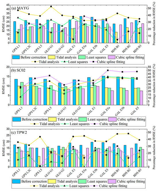
Figure 11.
Histogram of RMSE with and without dynamic height error correction at each station: (a) comparisons at MAYG station; (b) comparisons at SC02 station; (c) comparisons at TPW2 station.
4. Discussion
4.1. RMSE Variation in the Iterative Process of the Tidal Analysis Method
Due to the influence of various factors such as sea surface roughness and signal characteristics, outliers inevitably exist in the series, and it is difficult to completely eliminate them even through quality control. And these outliers can negatively affect the effectiveness of dynamic correction. In this study, the tidal analysis method (Figure 6) can eliminate these outliers and thus obtain better dynamic height correction in the iterative process, contributing to the higher overall precision over the other two methods. This iterative process has not been explicitly investigated in previous studies. Table 7 shows the number of iterations in the dynamic height error correction with tidal analysis in each system and frequency band at the three stations. The number of iterations is related to the outliers in the time series of GNSS-IR sea level retrievals, and it typically needs 3~5 iterations for convergence. Figure 12 shows the variation in the RMSE during the iterative process at GPS L1, GLONASS G1, Galileo E1 and BDS B1 frequencies at three stations. Taking the GPS L1 frequency at the MAYG station as an example, the RMSE of the series without the iterative process is up to 19.2 cm after the first dynamic height error correction. After the first iteration to eliminate outliers and recalculate the dynamic height error correction, the RMSE is reduced to 14.3 cm, indicating that the outliers have a significant impact on the precision of sea level retrieval. With the number of iterations increasing, the RMSE further decreases to 13.7 cm after the second iteration and then to 13.5 cm after the third iteration, and the results begin to converge thereafter. This result demonstrates that iterative outlier removal enhances the dynamic height error correction and the precision of sea level retrieval. Notably, although the reduction in RMSE begins to converge and even stabilize in subsequent iterations, this method can still effectively eliminate the remaining outliers in the series, thus ensuring the reliability of retrieved sea levels.

Table 7.
The number of iterations in the dynamic height error correction in the tidal analysis method in each system and frequency band at the MAYG, SC02 and TPW2 stations.

Figure 12.
(a) Variation in RMSEs in the iteration process for GPS L1, CLONASS G1, Galileo E1 and BDS B1 frequency bands at MAYG station; (b) Variation in RMSEs in the iteration process for GPS L1, CLONASS G1 and Galileo E1 frequency bands at SC02 station; (c) Variation in RMSEs in the iteration process for GPS L1, CLONASS G1, Galileo E1 and BDS B1 frequency bands at TPW2 station.
4.2. The Influence of Window Length and Step Size on the Least Squares Method
In the sliding window least squares method for dynamic height error correction in GNSS-IR sea level retrievals, the window length and movement step size determine the final correction effect. The window length and step size are four hours and half an hour, respectively, which generally perform well in various frequency bands across the three GNSS stations. Sufficient retrievals need to be included in each window for reliable least squares estimation. The processing scheme adopted by this study is to only output correction results for windows containing three or more retrievals. The least squares method has high requirements for the density of the original GNSS-IR sea level retrievals. Since the retrievals at SC02 station are densest among all three stations, we select the GNSS-IR sea level retrievals at three frequencies at SC02 station as the representatives to conduct analysis of the impact of window length and step size in the least squares method. Table 8 shows the number of retrievals and RMSEs of three frequency bands at SC02 station under the least squares correction with different window lengths and a fixed step size of half an hour. It can be seen from Table 8 that when the window length is 1 h and 2 h, the RMSEs of the three frequency bands are very small, but their retrievals are far less than that before correction. When the window length is 4 h, it achieves a relatively good correction effect and produces enough retrievals. With the window length extended to 6 h, the RMSEs significantly increase by 4~6 cm. Thus, in the case of dense original GNSS-IR sea level retrievals, the smaller the window length, the better the correction performance. This is because the linear equation in the least squares method can better approximate the local variations in sea level within a shorter time window. However, due to the requirement for individual retrievals in the original window, the smaller window length also means less retrievals after least squares estimation. Taking into account the number of retrievals and precision of the corrected data, we fixed the window length at 4 h. Table 9 shows the number of retrievals and RMSEs corrected using the least squares method with different movement steps. It can be seen that there is no significant difference in the RMSE in the retrievals with moving step sizes of 0.5 h, 0.8 h, and 1 h, respectively. As the step size increases, the number of retrievals decreases.

Table 8.
The number of retrievals and the RMSEs by the least squares method with different window lengths for the GPS L1, GLONASS G1, and Galileo E1 frequencies at SC02 station.

Table 9.
The number of retrievals and the RMSEs by the least squares method with different step sizes for the GPS L1, GLONASS G1, and Galileo E1 frequencies at SC02 station.
4.3. Merits and Limitations of the Three Methods
As the main error source in the GNSS-IR sea level retrievals, the dynamic height errors need careful correction. Despite the different strategies used, all three methods could effectively eliminate the dynamic height errors. All three methods are simple and easy to implement in the GNSS-IR process. Among these three methods, the least squares method is less effective. This may be attributed to the use of the simple linear model in the least squares method, which cannot accurately describe the actual sea level changes since the sea level moves smoothly and continuously and could not be simply modeled with a linear function over a certain period. If the retrievals are dense enough, the sea level could be approximated with the linear model in a short time. This explains the better performance at SC02 than that at the other two stations, as the number of daily retrievals at SC02 is 2~3 times that at the other two stations. Similarly to the least squares method, the cubic spline fitting method uses the spline to model the sea level variation node by node. The spline model is more accurate in describing the sea level than the linear model, resulting in better performance in dynamic height correction. However, the correction of cubic spline fitting also highly depends on the number of daily retrievals. With dense daily retrievals, the cubic spline fitting method could achieve very good performance in dynamic height error correction. As for the tidal analysis method, it works the most steadily at the experimental stations compared to the least squares method and cubic spline fitting method. Since it is based on the four primary diurnal tides and four semi-diurnal tides that predominantly influence sea level, the outliers can be eliminated efficiently, and the retrieved height rates can be well constrained during the iterative process. More importantly, this method has less dependence on the number of daily GNSS-IR sea level retrievals than other two methods. However, due to the constraints of normal diurnal and semi-diurnal tide components, it could incorrectly estimate the sea level as well as the height rate in storm or tsunami events. Figure 13 shows the GNSS-IR sea level retrievals corrected with three methods at the GPS L1 frequency at SC02 station on 13 January 2021. The strong wind measured by Friday Harbor station indicates a storm event on this day. From Figure 13, we can see that there is a significant discrepancy between the tide gauge sea level and the fitting sea level from tidal analysis. During the period of 8:00–13:00 UTC when the wind speed exceeded 15 m/s, the three original GNSS-IR retrievals were wrongly removed after the dynamic height error correction in the iterative process of the tidal analysis method. The reason is that strong wind speed caused violent changes in sea level, and these changes deviated significantly from the fitting sea level from tidal analysis. Thus, the preliminary GNSS-IR sea level retrievals in this period were wrongly identified as the outliers by the tidal analysis method. However, the least squares method and cubic spline fitting method were not impacted by the storm, and both methods could obtain retrievals with the dynamic height error correction. Thus, in normal situations, the tidal analysis method is preferred for dynamic height error correction due to its simple formulation and efficient calculation. In storm events, especially with dense daily GNSS-IR retrievals, the cubic spline fitting method is highly recommended, followed by the least squares method.
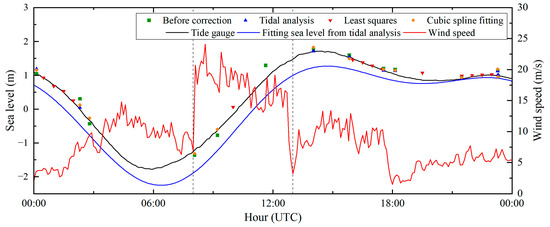
Figure 13.
The GNSS-IR sea level retrievals corrected with three methods at GPS L1 frequency at SC02 station on 13 January 2021. The sea level and wind speed measured by Friday Harbor as well as the fitting sea level from tidal analysis are also shown. The two black dashed lines represent 8:00 UTC and 13:00 UTC respectively.
This study processes and analyzes the multi-system and multi-frequency data from three stations one by one, demonstrating that all three methods have good universality in dynamic height error correction for GNSS-IR-retrieved sea levels. However, the sea level estimates retrieved from a single frequency band still have obvious deficiencies in terms of precision and temporal resolution. The integration of multi-system and multi-frequency data has gradually developed into a major hotspot in the field of GNSS-IR sea level retrieval, as it is capable of providing denser information on sea level variations. The combination of multi-system and multi-frequency GNSS-IR may solve the data sparsity problem in the least squares method and cubic spline fitting method, but the inter-system and inter-frequency biases need careful handling before the dynamic height error correction.
5. Conclusions
In this study, we compared and analyzed the correction performance of the tidal analysis method, least squares method based on sliding window, and cubic spline fitting method in GNSS-IR sea level retrievals at three coastal GNSS stations. We applied GNSS-IR to the multi-system and multi-frequency SNR data collected by the three GNSS stations to retrieve a 3-year-long sea level time series. Then, we applied the three methods to correct the dynamic height error in GNSS-IR sea level retrievals and compared the results with the in situ sea levels from tide gauges. The results indicate that all three methods can effectively correct the dynamic height error in sea level. At the MAYG and TPW2 stations, the tidal analysis method was significantly better than the other two methods, with the RMSE of each system and frequency band decreasing by an average of 39.3% (10.7 cm) and 37.6% (6.7 cm), respectively. At the SC02 station, the cubic spline fitting method showed the best correction effect, with an average reduction of 39.3% (5.5 cm) in RMSE for each frequency band. The tidal analysis method could effectively eliminate the outliers and obtain accurate height rates during the iterative process. Based on dense preliminary GNSS-IR sea level retrievals, the smaller the window length of the least squares method, the more the corrected retrievals and the better the correction performance. Our study also shows that the tidal analysis method has less dependence on the number of daily retrievals and can achieve good correction results even in sparse retrieval series. In contrast, the least squares method and cubic spline fitting method are more susceptible to the influence of data sparsity, but these two methods are more suitable for dynamic height correction in storm events. Moreover, these three methods are expected to enhance robustness in the future by integrating multiple-system and multi-frequency GNSS-IR sea level retrievals. To our knowledge, this is the first study to comprehensively analyze the performance of all three methods for a long period (i.e., three years). The iterative process of the tidal analysis and the impact of window length and step size of the least squares method on the correction performance are also discussed for the first time in our study.
Author Contributions
Y.H. provided the original idea for the study; Z.Z. and J.G. constructed experimental frameworks and models; Z.L. and X.L. collected relevant data; Z.Z. and Y.H. analyzed the results of the experiment and wrote the article. All authors have read and agreed to the published version of the manuscript.
Funding
This research was funded by the National Natural Science Foundation of China, grant number 42041006; the Natural Science Research Project of Shaanxi Province, grant number 2024JC-YBMS-197; the Fundamental Research Funds for the Central Universities, CHD, grant number 300102263203; the Shaanxi Province Geoscience Big Data and Geohazard Prevention Innovation Team (2022); Research Funds for the Interdisciplinary Projects, CHU, grant number 300104240914.
Data Availability Statement
Tide-gauge records are publicly available here: https://www.ioc-sealevelmonitoring.org/ and https://tidesandcurrents.noaa.gov/ (accessed on 1 August 2024). GNSS data are freely available here: https://www.unavco.org/ and https://cddis.nasa.gov/ (accessed on 1 August 2024).
Conflicts of Interest
The authors declare no conflicts of interest.
Appendix A
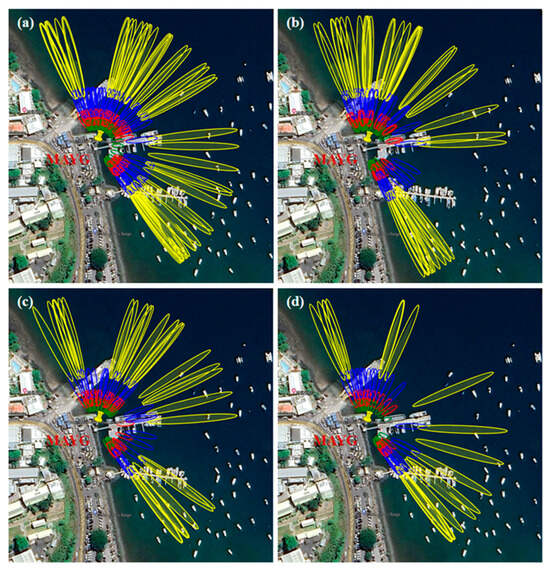
Figure A1.
The first Fresnel zones for GPS L1, GLONASS G1, Galileo E1 and BDS B1 at the MAYG station with yellow, blue, red, and green ellipses representing the sensing zones for elevation angles of 5°, 10°, 15°, and 20°, respectively.(a) GPS L1; (b) GLONASS G1; (c) Galileo E1; (d) BDS B1.
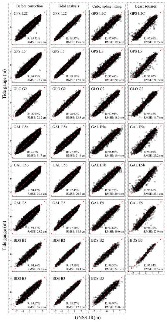
Figure A2.
Scatter plots of GNSS-IR-retrieved sea levels with and without dynamic height error corrections for other frequencies at MAYG versus tide gauge measurements. The 1:1 diagonal in each plot is shown as a red dashed line.
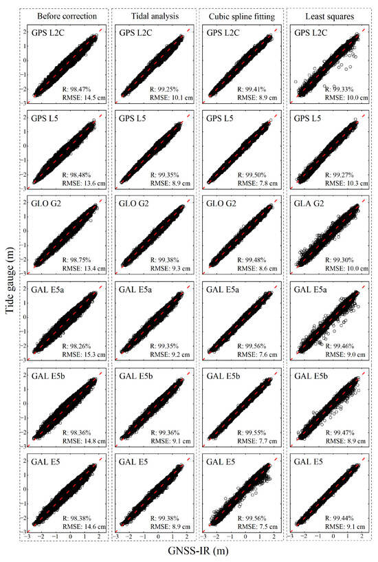
Figure A3.
Scatter plots of GNSS-IR-retrieved sea levels with and without dynamic height error corrections for other frequencies at SC02 versus tide gauge measurements. The 1:1 diagonal in each plot is shown as a red dashed line.
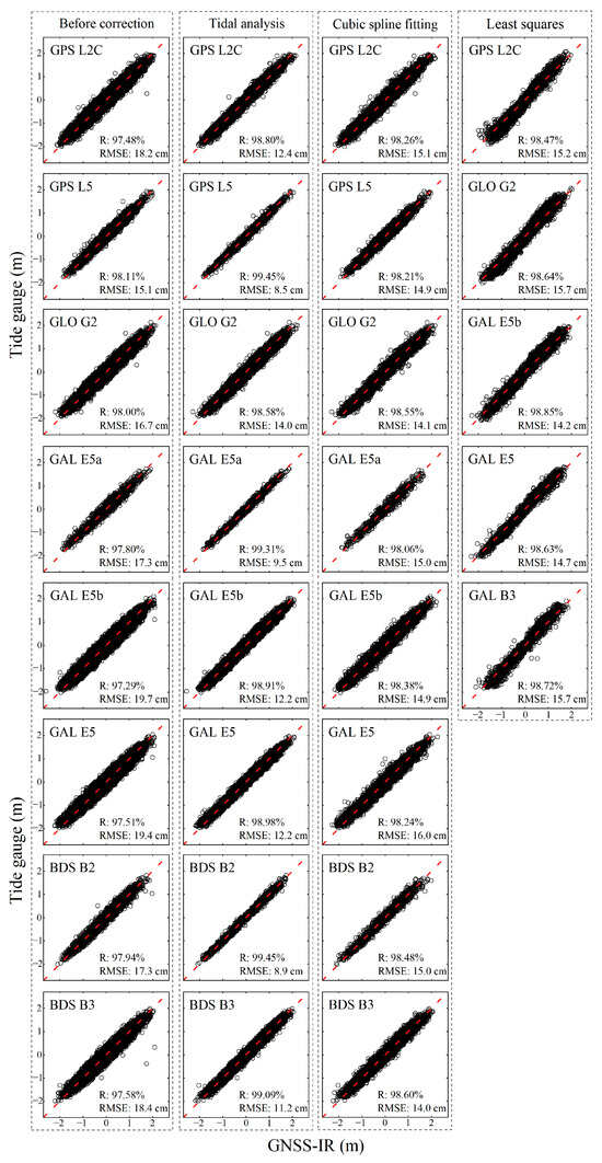
Figure A4.
Scatter plots of GNSS-IR-retrieved sea levels with and without dynamic height error corrections for other frequencies at TPW2 versus tide gauge measurements. The 1:1 diagonal in each plot is shown as a red dashed line.
References
- Chepurin, G.A.; Carton, J.A.; Leuliette, E. Sea level in ocean reanalyses and tide gauges. J. Geophys. Res. Ocean. 2014, 119, 147–155. [Google Scholar] [CrossRef]
- Cazenave, A.; Palanisamy, H.; Ablain, M. Contemporary sea level changes from satellite altimetry: What have we learned? What are the new challenges? Adv. Space Res. 2018, 62, 1639–1653. [Google Scholar] [CrossRef]
- Larson, K.M.; Small, E.E.; Gutmann, E.D.; Bilich, A.L.; Braun, J.J.; Zavorotny, V.U. Use of GPS receivers as a soil moisture network for water cycle studies. Geophys. Res. Lett. 2008, 35, L24405. [Google Scholar] [CrossRef]
- Zavorotny, V.U.; Larson, K.M.; Braun, J.J.; Small, E.E.; Gutmann, E.D.; Bilich, A.L. A physical model for GPS multipath caused by land reflections: Toward bare soil moisture retrievals. IEEE J. Sel. Top. Appl. Earth Obs. Remote Sens. 2009, 3, 100–110. [Google Scholar] [CrossRef]
- Chew, C.; Small, E.E.; Larson, K.M. An algorithm for soil moisture estimation using GPS-interferometric reflectometry for bare and vegetated soil. GPS Solut. 2016, 20, 525–537. [Google Scholar] [CrossRef]
- Small, E.E.; Larson, K.M.; Braun, J.J. Sensing vegetation growth with reflected GPS signals. Geophys. Res. Lett. 2010, 37, L12401. [Google Scholar] [CrossRef]
- Larson, K.M.; Small, E.E. Normalized microwave reflection index: A vegetation measurement derived from GPS networks. IEEE J. Sel. Top. Appl. Earth Obs. Remote Sens. 2014, 7, 1501–1511. [Google Scholar] [CrossRef]
- Li, J.; Yang, D.; Wang, F.; Hong, X. A new algorithm for measuring vegetation growth using GNSS interferometric reflectometry. IEEE J. Sel. Top. Appl. Earth Obs. Remote Sens. 2022, 16, 1033–1041. [Google Scholar] [CrossRef]
- Larson, K.M.; Gutmann, E.D.; Zavorotny, V.U.; Braun, J.J.; Williams, M.W.; Nievinski, F.G. Can we measure snow depth with GPS receivers? Geophys. Res. Lett. 2009, 36, L17502. [Google Scholar] [CrossRef]
- McCreight, J.L.; Small, E.E.; Larson, K.M. Snow depth, density, and SWE estimates derived from GPS reflection data: Validation in the western US. Water Resour. Res. 2014, 50, 6892–6909. [Google Scholar] [CrossRef]
- Larson, K.M.; Small, E.E. Estimation of snow depth using L1 GPS signal-to-noise ratio data. IEEE J. Sel. Top. Appl. Earth Obs. Remote Sens. 2016, 9, 4802–4808. [Google Scholar] [CrossRef]
- Siegfried, M.; Medley, B.; Larson, K.; Fricker, H.; Tulaczyk, S. Snow accumulation variability on a West Antarctic ice stream observed with GPS reflectometry, 2007–2017. Geophys. Res. Lett. 2017, 44, 7808–7816. [Google Scholar] [CrossRef] [PubMed]
- Löfgren, J.S.; Haas, R.; Scherneck, H.-G. Sea level time series and ocean tide analysis from multipath signals at five GPS sites in different parts of the world. J. Geodyn. 2014, 80, 66–80. [Google Scholar] [CrossRef]
- Strandberg, J.; Hobiger, T.; Haas, R. Improving GNSS-R sea level determination through inverse modeling of SNR data. Radio Sci. 2016, 51, 1286–1296. [Google Scholar] [CrossRef]
- Wang, X.; Zhang, Q.; Zhang, S. Sea level estimation from SNR data of geodetic receivers using wavelet analysis. GPS Solut. 2019, 23, 1–14. [Google Scholar] [CrossRef]
- Peng, D.; Feng, L.; Larson, K.M.; Hill, E.M. Measuring coastal absolute sea-level changes using GNSS interferometric reflectometry. Remote Sens. 2021, 13, 4319. [Google Scholar] [CrossRef]
- Zheng, N.; Chen, P.; Li, Z. Accuracy analysis of ground-based GNSS-R sea level monitoring based on multi GNSS and multi SNR. Adv. Space Res. 2021, 68, 1789–1801. [Google Scholar] [CrossRef]
- Peng, D.; Hill, E.M.; Li, L.; Switzer, A.D.; Larson, K.M. Application of GNSS interferometric reflectometry for detecting storm surges. GPS Solut. 2019, 23, 1–11. [Google Scholar] [CrossRef]
- Rodriguez-Alvarez, N.; Munoz-Martin, J.F.; Morris, M. Latest advances in the global navigation satellite system—Reflectometry (GNSS-R) field. Remote Sens. 2023, 15, 2157. [Google Scholar] [CrossRef]
- Jin, S.; Camps, A.; Jia, Y.; Wang, F.; Martin-Neira, M.; Huang, F.; Yan, Q.; Zhang, S.; Li, Z.; Edokossi, K. Remote sensing and its applications using GNSS reflected signals: Advances and prospects. Satell. Navig. 2024, 5, 19. [Google Scholar] [CrossRef]
- Jin, S.; Qian, X.; Wu, X. Sea level change from BeiDou Navigation Satellite System-Reflectometry (BDS-R): First results and evaluation. Glob. Planet. Chang. 2017, 149, 20–25. [Google Scholar] [CrossRef]
- Larson, K.M.; Löfgren, J.S.; Haas, R. Coastal sea level measurements using a single geodetic GPS receiver. Adv. Space Res. 2013, 51, 1301–1310. [Google Scholar] [CrossRef]
- Larson, K.M.; Ray, R.D.; Nievinski, F.G.; Freymueller, J.T. The accidental tide gauge: A GPS reflection case study from Kachemak Bay, Alaska. IEEE Geosci. Remote Sens. Lett. 2013, 10, 1200–1204. [Google Scholar] [CrossRef]
- Santamaría-Gómez, A.; Watson, C.; Gravelle, M.; King, M.; Wöppelmann, G. Levelling co-located GNSS and tide gauge stations using GNSS reflectometry. J. Geod. 2015, 89, 241–258. [Google Scholar] [CrossRef]
- Williams, S.; Nievinski, F. Tropospheric delays in ground-based GNSS multipath reflectometry—Experimental evidence from coastal sites. J. Geophys. Res. Solid Earth 2017, 122, 2310–2327. [Google Scholar] [CrossRef]
- Zeming, W.; Haojun, L.; Yafeng, S. Robust estimation of GNSS-R tide level monitoring. Acta Geod. Et Cartogr. Sin. 2023, 52, 195. [Google Scholar]
- Löfgren, J.S.; Haas, R. Sea level measurements using multi-frequency GPS and GLONASS observations. EURASIP J. Adv. Signal Process. 2014, 2014, 50. [Google Scholar] [CrossRef]
- Larson, K.M.; Ray, R.D.; Williams, S.D. A 10-year comparison of water levels measured with a geodetic GPS receiver versus a conventional tide gauge. J. Atmos. Ocean. Technol. 2017, 34, 295–307. [Google Scholar] [CrossRef]
- Roussel, N.; Ramillien, G.; Frappart, F.; Darrozes, J.; Gay, A.; Biancale, R.; Striebig, N.; Hanquiez, V.; Bertin, X.; Allain, D. Sea level monitoring and sea state estimate using a single geodetic receiver. Remote Sens. Environ. 2015, 171, 261–277. [Google Scholar] [CrossRef]
- Wang, X.; He, X.; Zhang, Q. Evaluation and combination of quad-constellation multi-GNSS multipath reflectometry applied to sea level retrieval. Remote Sens. Environ. 2019, 231, 111229. [Google Scholar] [CrossRef]
- Wang, X.; Niu, Z.; Chen, S.; He, X. A Correction Method of Height Variation Error Based on One SNR Arc Applied in GNSS–IR Sea-Level Retrieval. Remote Sens. 2021, 14, 11. [Google Scholar] [CrossRef]
- Roesler, C.; Larson, K.M. Software tools for GNSS interferometric reflectometry (GNSS-IR). GPS Solut. 2018, 22, 80. [Google Scholar] [CrossRef]
- Ye, M.; Jin, S.; Jia, Y. Ten-minute sea-level variations from combined multi-GNSS multipath reflectometry based on a weighted iterative least-square method. IEEE Trans. Geosci. Remote Sens. 2022, 60, 1–10. [Google Scholar] [CrossRef]
- Lomb, N.R. Least-squares frequency analysis of unequally spaced data. Astrophys. Space Sci. 1976, 39, 447–462. [Google Scholar] [CrossRef]
- Bennett, G. The calculation of astronomical refraction in marine navigation. J. Navig. 1982, 35, 255–259. [Google Scholar] [CrossRef]
- Böhm, J.; Möller, G.; Schindelegger, M.; Pain, G.; Weber, R. Development of an improved empirical model for slant delays in the troposphere (GPT2w). GPS Solut. 2015, 19, 433–441. [Google Scholar] [CrossRef]
- Stephenson, A. Harmonic Analysis of Tides Using TideHarmonics. 2016. Available online: https://CRAN.R-project.org/package=TideHarmonics (accessed on 1 August 2024).
Disclaimer/Publisher’s Note: The statements, opinions and data contained in all publications are solely those of the individual author(s) and contributor(s) and not of MDPI and/or the editor(s). MDPI and/or the editor(s) disclaim responsibility for any injury to people or property resulting from any ideas, methods, instructions or products referred to in the content. |
© 2024 by the authors. Licensee MDPI, Basel, Switzerland. This article is an open access article distributed under the terms and conditions of the Creative Commons Attribution (CC BY) license (https://creativecommons.org/licenses/by/4.0/).