Article

Modified Hybrid Integration Algorithm for Moving Weak Target in Dual-Function Radar and Communication System

School of Electronics and Communication Engineering, Shenzhen Campus of Sun Yat-sen University, Shenzhen 518107, China
*
Author to whom correspondence should be addressed.
Remote Sens. 2024, 16(19), 3601; https://doi.org/10.3390/rs16193601
Submission received: 17 August 2024 / Revised: 15 September 2024 / Accepted: 20 September 2024 / Published: 27 September 2024

Abstract

:
To detect moving weak targets in the dual function radar communication (DFRC) system of an orthogonal frequency division multiplexing (OFDM) waveform, a modified hybrid integration method is addressed in this paper. A high-speed aircraft can cause range walk (RW) and Doppler walk (DW), rendering traditional detection methods ineffective. To overcome RW and DW, this paper proposes an integration approach combining DFRC and OFDM. The proposed approach consists of two primary components: intra-frame coherent integration and hybrid multi-inter-frame integration. After the echo signal is re-fragmented into multiple subfragments, the first step involves integrating energy across fixed situations within intra-frames for each subcarrier. Subsequently, coherent integration is performed across the subfragments, followed by the application of a Radon transform (RT) to generate frames based on the properties derived from the coherent integration output. This paper provides detailed expressions and analyses for various performance metrics of our proposed method, including the communication bit error ratio (BER), responses of coherent and non-coherent outputs, and probability of detection. Simulation results demonstrate the effectiveness of our strategy.

1. Introduction

In recent years, radar and communication equipment has grown increasingly complex due to rapid technological advancements. Radar systems are essential in tracking and detecting targets [1,2,3], while communication devices serve to transmit information [4]. In certain applications, there is a need to not only detect targets but also provide communication capabilities. For instance, in smart transportation systems, base stations detect vehicle conditions and relay this information to other devices or base stations [5,6,7,8,9]. Similarly, unmanned aerial vehicles (UAVs) require the communication of air transportation information. To integrate radar and communication functionalities into a single device, digital signal processing techniques are indispensable. Integrated radar and communication systems (IRCSs) have garnered significant attention from researchers [10,11,12,13,14]. IRCSs involve hardware and software integration to merge radar and communication capabilities [15,16,17]. Central to IRCSs is the design of integrated radar and communication waveforms (IRCW), which unify radar and communication operations using the same waveform. Researchers have developed various IRCWs, categorized primarily into common waveforms and multiplexing waveforms [10,11,12,13,14,15,16,17,18,19,20,21,22]. Multiplexing waveforms encompass techniques such as space division multiplexing, time division multiplexing, frequency division multiplexing, and code division multiplexing. Among these, the orthogonal frequency division multiplexing (OFDM) waveform stands out, widely recognized for its application in digital television broadcasting [23], digital video [24,25,26,27], and wireless local area networks (WLANs) [28,29,30]. OFDM has also gained prominence in radar applications, including synthetic aperture radar (SAR) imaging [31], space-time adaptive processing (STAP) [32], radar target detection, and parameter estimation [33,34,35]. Consequently, extensive research focuses on OFDM IRCW, covering waveform design, ambiguity analysis, and receiving signal parameter estimation [36].
Due to differences between the DFRC OFDM waveform and traditional OFDM radar waveforms, the direct application of conventional radar parameter estimation methods for target detection is not feasible. OFDM radar typically employs pulse waveforms [32,33,34], whereas DFRC OFDM integrates communication signals, resulting in unique variations across each OFDM symbol. This variation complicates the application of standard radar target detection algorithms in DFRC systems. Christian Sturm addresses this challenge by proposing an integrated OFDM radar and communication waveform approach, allowing the separate determination of the range and velocity. However, the algorithm described in [8] is effective primarily under the conditions of a high signal-to-noise ratio (SNR) and when the target echo energy is concentrated within the same range cell. The performance of detection is increasingly affected by advancements in stealth techniques and the presence of numerous moving targets, such as birds and UAVs. It is well known that the long-term integration of multiple sampling pulses significantly enhances the radar detection performance, addressing these challenges [37,38,39,40].
Building upon the long-time coherent integration algorithm, several scholars have proposed intra-frame integration techniques. Carlson et al. proposed the Hough transform (HT) for the accumulation of energy from moving targets with a range walk (RW) [36,41,42]. Perry et al. proposed the Keystone transform (KT), which utilizes range–frequency scaling to correct range ambiguities (RA) [43,44]. Xu et al. proposed the Radon Fourier transform (RFT) to achieve intra-frame coherent integration by leveraging the coupling between target motion and RW [45,46,47,48,49,50]. In addition to intra-frame methods, researchers have also proposed inter-frame integration approaches [51,52]. These methods enable the multi-frame integration of target energy, thereby enhancing the target detection performance. It is noteworthy that these inter-frame integration methods do not account for the RA of moving targets, assuming that the range walk within each frame is less than one range unit. Consequently, the performance gain from intra-frame integration is constrained by the target’s residency time within a single range unit. However, to our knowledge, these methods are predominantly applied in radar signal processing. Research addressing RA and low signal-to-noise ratios (SNRs) in DFRC OFDM signal processing remains sparse in the open literature, forming the primary focus of this study.
In this paper, we propose joint intra-frame coherent integration and inter-multi-frame coherent integration for the DFRC OFDM signal processing of moving weak targets with RW during the observation time. The main steps are summarized as follows.
(1) Intra-frame integration along the symbol axis is introduced to integrate energy within one OFDM frame, enabling the extraction of the speed information of targets within a single frame.
(2) A multi-frame hybrid coherent integration approach is proposed, combining intra-frame integration across different OFDM frames with incoherent methods across subframes. This method leverages the integration gain from intra-frame and inter-frame coherent accumulation to enhance the SNR and improve the detection performance of the DFRC OFDM system.
(3) The paper provides the formulation, reasoning, and analysis of various performance metrics for the proposed DFRC OFDM algorithm, including the communication bit error ratio and output response probability of detection at different SNRs. Detailed numerical experiments are presented to demonstrate its effectiveness.
The remainder of this paper is organized as follows. Section 2 presents the DFRC OFDM transmit and receive signal model. Section 3 details intra-frame and inter-frame coherent integration, along with the modified generalized Radon transform. Section 4 provides a performance analysis of the methods discussed. Section 5 includes the experimental results and SNR analysis. Conclusions are drawn in Section 6.

2. Signal Model

Assume that S subcarriers are presented in the baseband DFRC OFDM signal, each consisting of N s OFDM symbols, referred to as one-frame OFDM in this paper, included within a single pulse. After modulation, the OFDM signal for p pulses is described as
s ( t ) = p = 0 P 1 n = 0 N s 1 s = 0 S 1 a s , n , p e j 2 π s Δ f ( t n T s p T p ) r e c t [ t n T s p T p T s ] ,
where a s , n , p is communication information modulated on the sth subcarrier, with the nth OFDM symbol in the pth pulse; T s is the length of a single OFDM symbol; and T p is the length of a single pulse. S denotes the total number of subcarriers, and Δ f denotes the subcarrier frequency spacing. r e c t [ t / T s ] is a rectangular function defined such that, when 0 t T s , r e c t [ t / T s ] equals 1; otherwise, it equals 0.
The purpose of a cyclic prefix (CP) is to mitigate the inter-symbol interference (ISI) arising from multipath effects within the communication channel. The length of the CP must exceed the maximum delay time caused by multipath propagation, denoted as t d max . Specifically, the condition max t d max , 2 R l / c | l = 0 , 1 , , L 1 < T g must be satisfied. Therefore, the transmitted signal with the CP can be expressed as
s C P ( t ) = p = 0 P 1 n = 0 N s 1 s = 0 S 1 { a s , n e j 2 π s Δ f ( t n T s n T c p p T p ) × r e c t [ t n T s n T c p p T p T s ] } ,
where T c p is the duration after adding the CP.
The transmitted OFDM-integrated radar and communication waveform is
x ( t ) = s c p ( t ) e j 2 π f c t ,
where f c is the frequency of carriers.
At the receiver, we observe the superposition of echoes reflected from all scatters within the detection area. The Taylor series expansion of the motion parameter R i for the ith scattering point is given by
R l ( t ) = R l + v l t ,
where R l , v l is the initial range and velocity of the l th target.
Assuming that there are L targets in the environment, the multipath received signal in (4) is converted to the baseband signal as
z ( t ) = l = 0 L 1 p = 0 P 1 n = 0 N s 1 s = 0 S 1 { ψ l a s , n e j 2 π s Δ f ( t n T s p T p n T c p 2 R l ( t ) c ) e j 2 π f c 2 R l ( t ) c e j 2 π f d l t r e c t t n T s n T c p p T p 2 R l ( t ) / c T s } + n ( t ) ,
where n ( t ) represents environmental noise, c is the light velocity, and ψ l signifies the attenuation factor due to the propagation loss, scattering, and radar cross-section (RCS) of the lth target. Since OFDM is a narrowband signal, the frequency dependence of ψ l can be neglected. Therefore, we assume that the attenuation factor ψ l is frequency-independent in this paper. As the RCS of the lth target increases, the attenuation factor ψ l also increases, thereby enhancing the estimation accuracy for the lth target.
After downconverting the received signal to the baseband, the formulation of the received signal is
z ( t ) = l = 0 L 1 p = 0 P 1 n = 0 N s 1 s = 0 S 1 ψ l a s , n e j 2 π s Δ f ( t n T s p T p T c p 2 R l ( t ) c ) e j 2 π f d l t r e c t [ t n T s T c p p T p ( 2 R l ( t ) / c ) T s ] + n ( t ) .
The sample interval is τ = 1 / f s , and the time-discrete signal of the kth time sample could be reformulated as
z ( k ) = l = 0 L 1 p = 0 P 1 n = 0 N s 1 s = 0 S 1 { ψ l a m , n e j 2 π s Δ f ( k n T s p T p T g 2 R ( k ) l c ) e j 2 π f d l t r e c t [ k n T s T c p p T p ( 2 R l ( k ) / c ) T s ] } + n ( k ) .
Suppose that the sampling frequency is f s = 1 / S Δ f = T / S , the sample interval is τ = 1 / f s , and the time-discrete S time samples can be obtained in one symbol. Removing the CP, the sth OFDM symbol, pth pulse, and kth time sample can be represented as
z n , p ( k ) = l = 0 L 1 s = 0 S 1 e j 2 π f c 2 R l 2 v l ( k Δ t + T C P + n T s + p T p ) / c · ψ l a s , n , p e j 2 π s Δ f 2 R l 2 v l ( k / s Δ f + T C P + n T s + p T p ) / c + n n , p ( k ) .

3. Modified Hybrid Integration Processing

This section will introduce the modified hybrid integration algorithm (MHI). Initially, the communication information was compensated for, and the frequency modulation symbol frame was established. Next, the MHI algorithm is elaborated, including the coherent intra-frame integration and hybrid inter-frame integration of subfragments. Finally, the calculation results for the detection probability ( P d ) and false alarm probability ( P f a ) are provided. The detailed flowchart of the MHI is shown in Figure 1.

3.1. Communication Compensation of Receiver Signal

The signal in (7) includes the communication information and parameters. In the receiver, the communication information will interfere with the range and velocity estimations. Hence, in order to obtain the range and velocity estimations, the communication information is compensated for first. Let β R , l = e j 2 π f c 2 R l / c , β ˜ v , l ( n ) = e j 2 π f c 2 v l n T s / c , β v , l ( p ) = e j 2 π f c 2 v l p T p / c , and (8) can be rewritten as
z n , p ( k ) = l = 0 L 1 s = 0 S 1 ψ l β R , l β v , l β ˜ v , l ( n ) β v , l ( p ) a s , n , p · e j 2 π s ( 1 + 2 v l / c ) k / S e j 2 π s Δ f 2 R l / c e j 2 π s Δ f 2 v i T C P / c · e j 2 π s Δ f 2 v i n T s / c e j 2 π s Δ f 2 v i p T p / c e j 2 π s Δ f 2 v i k Δ t / c + n n , p ( k )
Stack the z n , p ( k ) into a vector z n , p = z n , p ( 0 ) , z n , p ( 1 ) , , z n , p ( S 1 ) T , and let n n , p ( k ) = n n , p ( 0 ) , n n , p ( 1 ) , , n n , p ( S 1 ) T , a n , p = a 0 , n , p , a 1 , n , p , , a S 1 , n , p T , ρ l = 1 + 2 v l / c ,
F ( ρ l ) = 1 1 1 1 e j 2 π ρ l / S e j 2 π ( S 1 ) ρ l / S 1 e j 2 π ρ l ( S 1 ) / S e j 2 π ( S 1 ) ρ l ( S 1 ) / S ,
and u ˜ ( R l ) = 1 , e j 2 π Δ f 2 R l / c , , e j 2 π ( S 1 ) Δ f 2 R l / c T , u n , p ( v l ) = [ 1 , e j 2 π Δ f 2 v l ( T C P + n T s + p T p ) / c , e j 2 π ( S 1 ) Δ f 2 ( T C P + n T s + p T p ) / c ] T , u ( v l ) = 1 , e j 2 π f c 2 v l Δ t / c , , e j 2 π ( S 1 ) f c 2 v l ( S 1 ) Δ t / c T .
Stack S time samples of nth OFDM symbol and pth pulse into a column vector as follows:
z n , p = l = 0 L 1 ψ l β R , l β v , l β ˜ v , l ( n ) β v , l ( p ) D u ( v l ) · D u n , p ( v l ) F ( ρ l ) D c n , p u ˜ ( R l ) + n n , p ,
where D = d i a g denotes a diagonal matrix with the diagonal elements.
Note that e j 2 π ( S 1 ) Δ f 2 ( T C P + n T s + p T p ) / c and e j 2 π ( S 1 ) f c 2 v l ( S 1 ) Δ t / c are approximately 1, since f c is usually as large as c when v i ( S 1 ) Δ t is usually much less than 1, and ( S 1 ) Δ f is usually much less than c when 2 v i ( T C P + p T p + n T s ) is usually much less than 1. Therefore, d i a g u ( v l ) is approximately I S and d i a g u n , p ( v l ) is approximately I S . Moreover, since 2 v l / c 1 , ρ l 1 , F ρ 1 F 1 = F , F is the S × S inverse fast Fourier transform (IFFT) matrix. Meanwhile, (11) can be rewritten as
z n , p = l = 0 L 1 ψ l β R , l β v , l β ˜ v , l ( n ) β v , l ( p ) F ( ρ l ) D c n , p u ˜ ( R l ) + n n , p
The frequency domain signal can be obtained by multiplying FFT matrix F 1 and matrix D 1 c n , p by both sides in (12) as follows:
F 1 D 1 c n , p z n , p = β R , l β v , l β ˜ v , l ( n ) β v , l ( p ) u ˜ ( R l ) + n ˜ n , p ,
where n ˜ n , p = F 1 D 1 c n , p n n , p .
Stacking all time samples of the nth symbol within one pulse into a vector yields
z n = l = 0 L 1 ψ l β R , l β v , l β ˜ v , l u ˜ ( v l ) u ˜ ( R l ) + n ˜ n ,
where z n = z n , 0 T , z n , 1 T , , z n , P 1 T T , n ˜ n = n ˜ n , 0 T , n ˜ n , 1 T , , n ˜ n , P 1 T T , u ˜ ( v l ) = [ β v , l ( 0 ) β v , l ( 1 ) β v , l ( P 1 ) ] T and ⊗ denotes the Kronecker product.
Let Z = z 0 , z 1 , , z N s 1 T , y ˜ i ( n ) = ψ l β R , l β v , l β ˜ v , l ( n ) , y ˜ l = y ˜ l ( 0 ) , y ˜ l ( 1 ) , , y ˜ l ( N s 1 ) T , N = n ˜ 0 , n ˜ 1 , , n ˜ N s 1 T , A ( v , R ) = u ˜ ( v 0 , R 0 ) , u ˜ ( v 1 , R 1 ) , , u ˜ ( v L 1 , R L 1 ) T and u ˜ ( v l , R l ) = u ˜ v l u ˜ ( R l ) . The received signal can be rewritten as
Z = A ( v , R ) y ˜ l + N .

3.2. DFRC OFDM Radar Signal in Modulation Symbol Frequency

Since ψ l , β R , l , β v , l ( p ) and β v , l are constant values within one pulse, we can ignore noise N , ψ l , β R , l , β v , l ( p ) and β v , l from (15), and Z is decomposed into R and V :
R = 0 , exp j 2 π Δ f 2 R c , , exp j 2 π ( N s 1 ) Δ f 2 R c ,
and
V = 0 , exp j 2 π T O F D M f d , l , , exp j 2 π ( S 1 ) T O F D M f d , l ,
where f d , l = 2 v l / λ , λ = c / f c and T O F D M represents the time duration of one symbol.
Then, Y can be rewritten as follows:
Z p = V R .
The frequency modulation symbol frame of Z is considered as a matrix:
Z p = g ( 0 , 0 ) g ( 1 , 0 ) g ( N s 1 , 0 ) g ( 0 , 1 ) g ( 1 , 1 ) g ( N s 1 , 1 ) g ( 0 , S 1 ) g ( 1 , S 1 ) g ( N s 1 , ( S 1 )
where each column represents one OFDM symbol and each row represents a subcarrier.
If the bandwidth of the OFDM signal is significantly narrower than the carrier frequency, it can be seen that, for a fixed OFDM symbol index and a single modulation symbol, the Doppler frequency induces an identical phase shift across all subcarriers. The Doppler effect causes a linear phase shift between successive modulation symbols at a fixed subcarrier index n, corresponding to a phase change of 2 π f d , l over the entire transmitted OFDM symbol duration. Additionally, the phase shift between successive modulation symbols on a single subcarrier is not affected by the distance to the reflecting object. The key observation is that the modulation symbols are influenced orthogonally by the range and Doppler effects generated by reflecting objects, respectively. Doppler introduces a linear phase change only along the time axis, whereas the range introduces a linear phase shift along the frequency axis. This orthogonality is feasible when the observation time is short enough for the reflecting object to remain within a range-resolution cell. Therefore, effective signal processing techniques must enable the separate recovery of range and Doppler information.

3.3. Modified Hybrid Integration of OFDM IRCS Frequency Signal

In this section, the modified hybrid integration method is introduced in two steps, named intra-frame integration and multi-frame integration. The total integration time T is divided into N c subfragments without the constraint of a single pulse. Each subfragment contains multiple frames of OFDM symbols, and the duration of each subfragment is T c = T / N c , where N c = S . For convenience, we refer to the integration within each subfragment as intra-frame integration and that across subfragments as multi-frame integration.
A critical step in implementing multi-frame processing is determining the subfragment duration T c . The maximum allowable subfragment duration, considering velocity effects, is crucial to prevent RW within a single subfragment:
T c T A R U = c 2 v max f s ,
where v max denotes the maximum radial speed of the detected target and f s is the sampling frequency.

3.3.1. Intra-Frame Integration

A linear phase shift is induced between each reflected subcarrier from a target at range R. The high-order motion of the targets can be ignored because it does not result in Doppler crossing within one frame of OFDM IRCS. Thus, range information is discernible through the linear phase shift of the modulation symbols along the frequency axis. We can proceed directly to moving target detection (MTD) as follows:
v f r a m e ( k ) = n = 0 N s 1 exp j 2 π n T O F D M f d exp j 2 π N s n k ,
where k is denoted by
k = N s T O F D M f d ,
which efficiently accumulates intra-frame energy within one subfragment. The workflow resembles Figure 2.

3.3.2. Multi-Inter-Frame Integration

As shown in Figure 3, the multi-inter frame integration is finished and based on the characteristics of multi-inter frame integration outputs outlined earlier, we use the multi- Generate Radon Transform (GRT) to achieve the inter-frame integration along the range dimension between the sub-fragments of the frequency symbol matrix like Figure 4 is as follow
r m u l t i f r a m e ( u ) = ζ R 1 N c m = 0 p N c exp ( j 2 π m Δ f 2 R c ) exp ( j 2 π m p N c u ) ,
where ζ R = e j 4 π f c R / c denotes the echo RCS coefficient, and u represents the index corresponding to the range. The peak index is determined by
u = 2 R Δ f p N c c ,
where l corresponds to the index of parameter R, and the energy from different ranges is coherently integrated as (23). It is observed that the two exponential terms in (23) result in a unity index u in the time response r ( u ) . This leads to a peak in the subfragment, and the position of the subfragment is determined by
C s u b p e a k = C s u b N s T O F D M f d , 2 R Δ f p N c c = C s u b ( k , u ) .

4. Performance Analysis of Different Methods

In this section, we will further investigate the SNR and computational complexities of different methods. Approaches such as MTD and hybrid integration (HI), which have been used in radar signal processing, are used for comparison with the MHI.

4.1. SNR Gains of Different Methods for Highly Maneuvering Targets

The total SNR can be obtained by summing three SNR components:
S N R t o t a l = S N R intra f r a m e + S N R inter f r a m e + S N R m u l t i f r a g m e n t s
where S N R intra f r a m e , S N R inter f r a m e , and S N R m u l t i f r a g m e n t s represent the SNRs for intra-frame integration, inter-frame integration, and multi-subfragment integration, respectively.
In the aforementioned methods, intra-frame and multi-frame integration involve coherent integration, while multi-subfragment integration is noncoherent integration. We assume that the SNR gain of N point coherent integration is N times that of the single-point gain, and the SNR gain of N point noncoherent integration is N times that of the single-point gain. Assuming that no ARU and ADU effects occur in a single subfragment, the SNR gain of two-step CI in one subfragment is
G S N R , C I = G S N R , C I , intra f r a m e + G S N R , C I , inter f r a m e = N s + N c N l o n g N s u b
where N c is the number of discrete points in one frame, N s y is the number of discrete points in one symbol, T s is the length of one subfragment, N l o n g is the total number of frames in the MHI, and N s u b is the number of frames in one subfragment.
Comparatively, the SNR gain for each subfragment’s noncoherent integration algorithm is
G S N R , N I , M u l t i f r a g m e n t s = N l o n g
Therefore, the SNR gain of MHI and HI is
G M H I = G S N R , C I + G S N R , N I = N s + N c N s u b + N l o n g
G H I = N s + N c + N l o n g

4.2. Computational Complexities of Different Methods

We assume that M pulses are transmitted, with each pulse containing one frame of OFDM symbols. The subfragments encompass multiple pulses to demonstrate the computational efficiency of the three techniques. Each subfragment has a length of N s u b and contains N c frequency points per symbol.
For intra-frame and inter-frame coherent integration within one subfragment, the computational complexity in complex operations is
C a , C I = N s u b N c 2 log 2 ( N s u b N c ) · I m , c + N s 2 log 2 ( N s ) · I m , c + 2 N s u b N c log 2 ( N s u b N c ) · I a , c + 2 N s log 2 ( N s ) · I a , c
For comparison, the computational complexities of the noncoherent method across different frames can be expressed as
C a , N I = M I a , c N r N c N v
where I m , c , I a , c represent the complexities of complex addition and complex multiplication.
Therefore, the complexities of MHI, MI and MTD in OFDM IRCS are as follows:
C a , M H I = N s u b N c 2 log 2 ( N s u b N c ) · I m , c + N s 2 log 2 ( N s ) · I m , c + 2 N s u b N c log 2 ( N s u b N c ) · I a , c + 2 N s log 2 ( N s ) I a , c ˙ + N s u b I a , c N r N c N v
C a , H I = N c 2 log 2 ( N c ) · I m , c + N s y 2 log 2 ( N s y ) · I m , c + 2 N c log 2 ( N c ) · I m , c + 2 N s y log 2 ( N s y ) · I m , c + M I a , c N r N c N v
C a , M T D = N c 2 log 2 ( N c ) · I m , c + N s 2 log 2 ( N s ) · I m , c + 2 N c log 2 ( N c ) · I m , c + 2 N s log 2 ( N s ) · I m , c
Given that both operations require only one machine cycle on advanced digital signal processors, the real multiplication operation I a , c is considered as one real floating-point operation (Flop) in the analysis presented below. Four real additions, two real multiplications, and two real divisions constitute I m , c . Therefore, defining the computational complexity of the two methods as I m , c = 3 Flops, I a , c = 1 Flop, the complexity of the proposed method compared to other methods is as shown in Table 1.

5. Numerical Results

To evaluate the performance of the proposed algorithm in terms of different aspects, such as the communication symbol error rate and radar detection performance, numerical examples are provided in this section. The radar performance for the detection of moving weak targets includes both the OFDM intra-frame response and inter-frame integration response within one subfragment. Subsequently, we compare these different approaches.

5.1. Radar Detection Performance Analysis

The radar and target’s parameters are detailed in Table 2.

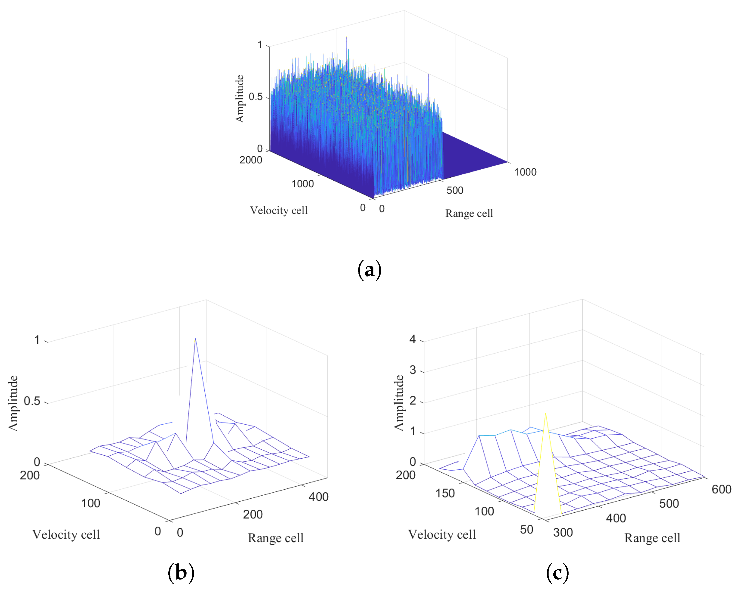
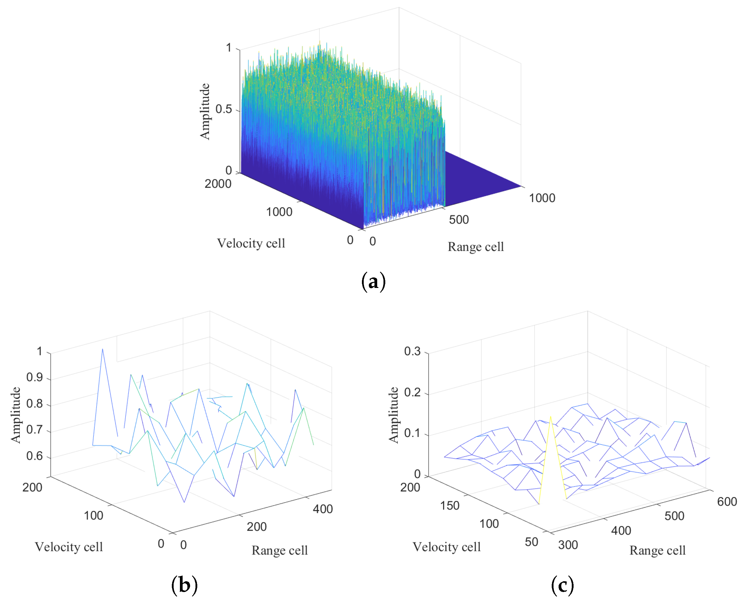
5.1.1. Integrated Output Response

Assuming the initial parameters of the target as [60 m, 150 m/s, 30 m/s2], and considering complex Gaussian noise with zero mean, various simulation experiments are conducted to demonstrate the effectiveness of the proposed approach. Figure 5a illustrates the distribution of the echo energy among different range cells. Figure 5b depicts the output of intra-frame integration, showcasing the energy distribution within a single range cell. Figure 5c shows the inter-frame integration of one subfragment. Figure 5d,e display Doppler cell and range cell cross-section slices, respectively, providing a clearer visualization of the integration results compared to the theoretical results. The experiment underscores the close alignment of the proposed method with the theoretical curves.

5.1.2. Different Methods’ Output Responses

In this subsection, the integration output responses for each method are provided in ( S N R = 20 dB). The normalized results are as follows: Figure 6a shows the result of the moving target detection (MTD) method, where the target integration is not apparent. Figure 6b displays the result of the multi-frame integration method, where the target is integrated but noise and sidelobes are prominent. Figure 6c presents the result of the proposed method, demonstrating lower sidelobes.

5.1.3. Integration for Weak Targets

In this subsection, the integration output responses for each method are provided in S N R = 15 dB, with motion parameters identical to those detailed in the preceding section. Figure 7a depicts the integration output response for MTD, Figure 7b for MFI, and Figure 7c illustrates the results of the proposed method. The findings from the simulation studies on weak-target scenarios indicate that the proposed MHI method effectively integrates the energy of weak targets compared to other approaches.

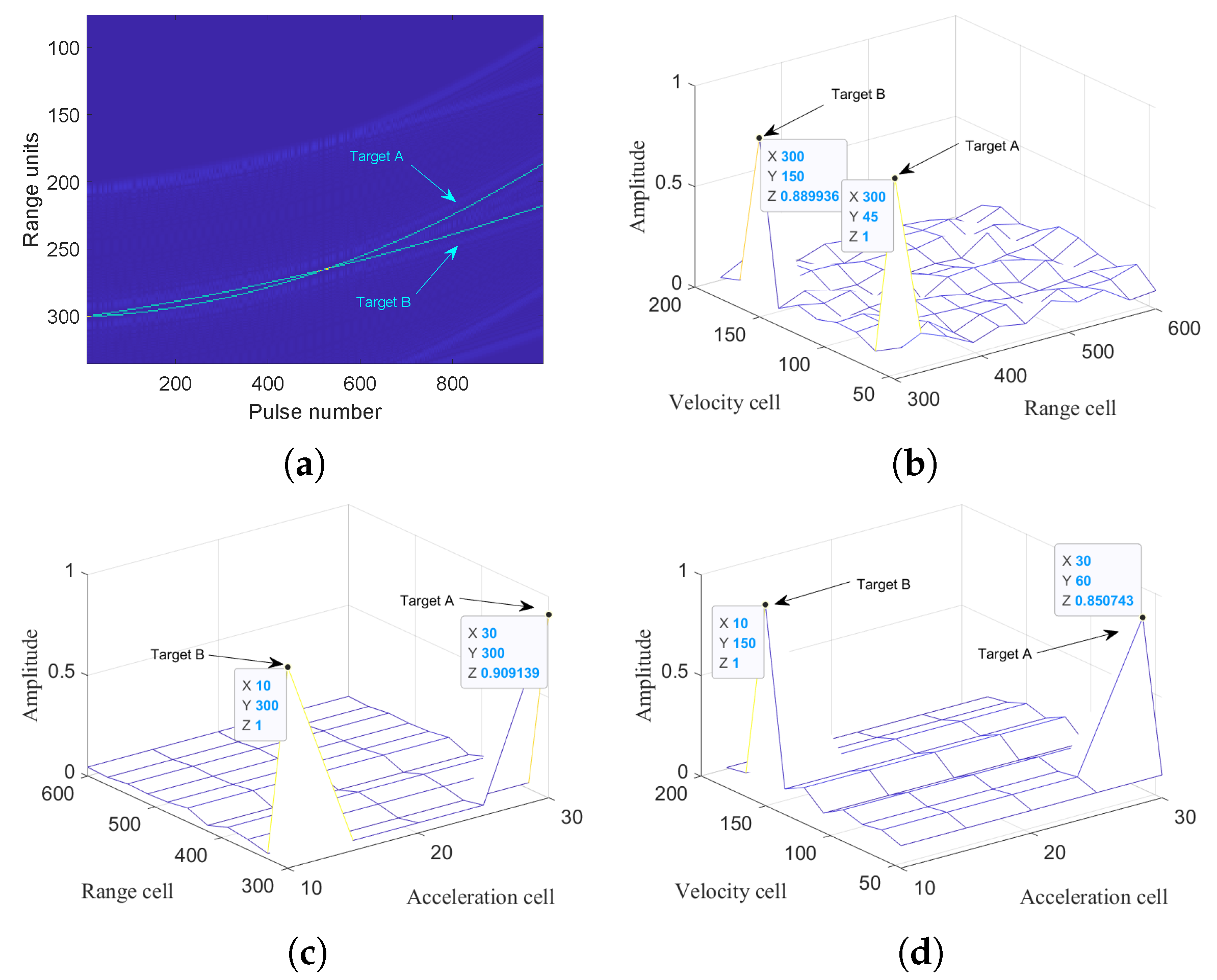
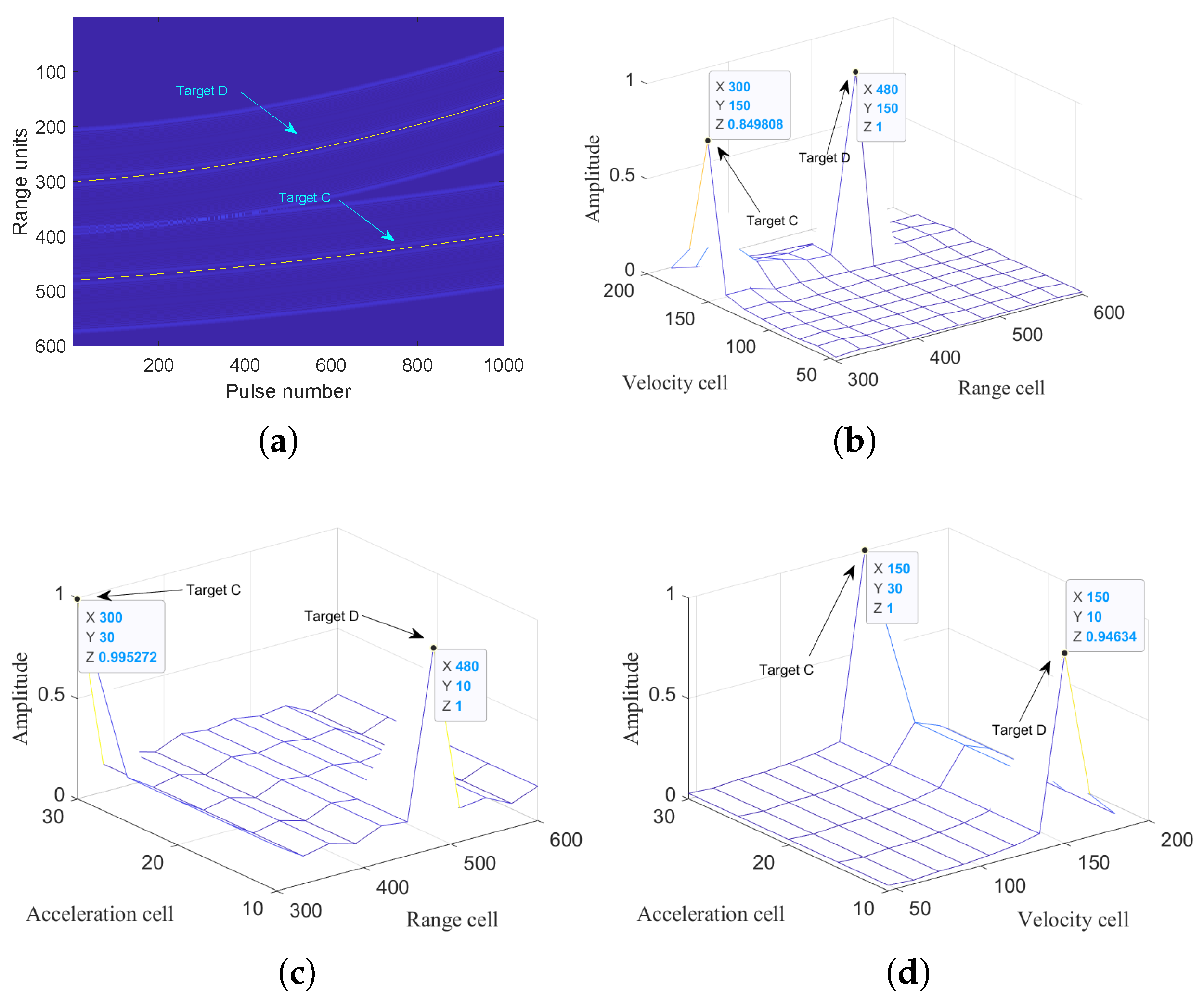
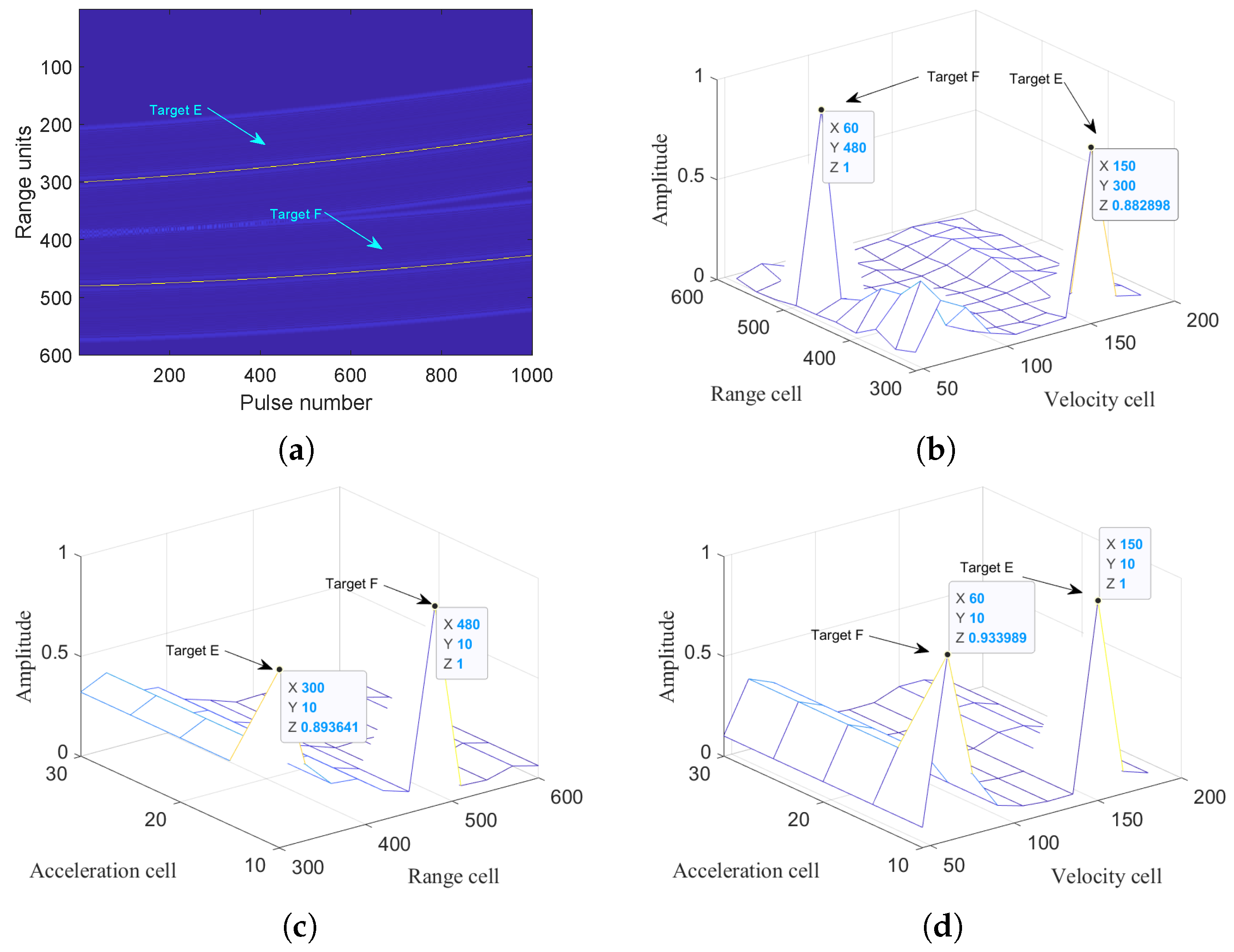
5.1.4. Integration for Multi-Targets

In this subsection, we present numerous simulation experiments to evaluate the multi-target integration performance of the proposed method when S N R = 10 dB.

Scenario 1

Targets with the same distance and different velocities and acceleration are considered. Targets A and B are positioned at an initial distance of 300 range cells, corresponding to 9000 m. Target A has a velocity of [60 m/s, 30 m/s2] and Target B has a velocity of [150 m/s, 10 m/s2]. Figure 8a illustrates the trajectories of targets A and B. Figure 8b–d depict the integration results on the range–velocity, range–acceleration, and velocity–acceleration planes, respectively, demonstrating the effectiveness of the proposed algorithm in signal integration.

Scenario 2

Targets with the same initial velocity and different ranges and acceleration are considered. The initial velocity of target C and target D is 150 m/s, with initial ranges and accelerations of [9000 m, 30 m/s2] for target C and [14,400 m, 10 m/s2] for target D, respectively. Figure 9a depicts the trajectories of targets C and D. Figure 9b–d show the integration results on the range–velocity, range–acceleration, and velocity–acceleration planes, respectively, demonstrating the outcomes after processing using the proposed algorithm. The results illustrate that the algorithm effectively concentrates the energy in the corresponding scenarios.

Scenario 3

Targets of the same acceleration and different initial distances and velocities are considered. The velocity of target E and target F is 10 m/s2, while the initial ranges and accelerations of target E and target F are [9000 m, 150 m/s] and [14,400 m, 60 m/s]. Figure 10a depicts the trajectories of targets E and F. Figure 10b–d illustrate the integration results on the range–velocity, range–acceleration, and velocity–acceleration planes after processing with the proposed algorithm. All results demonstrate that the energy peak aligns with the corresponding target parameters.

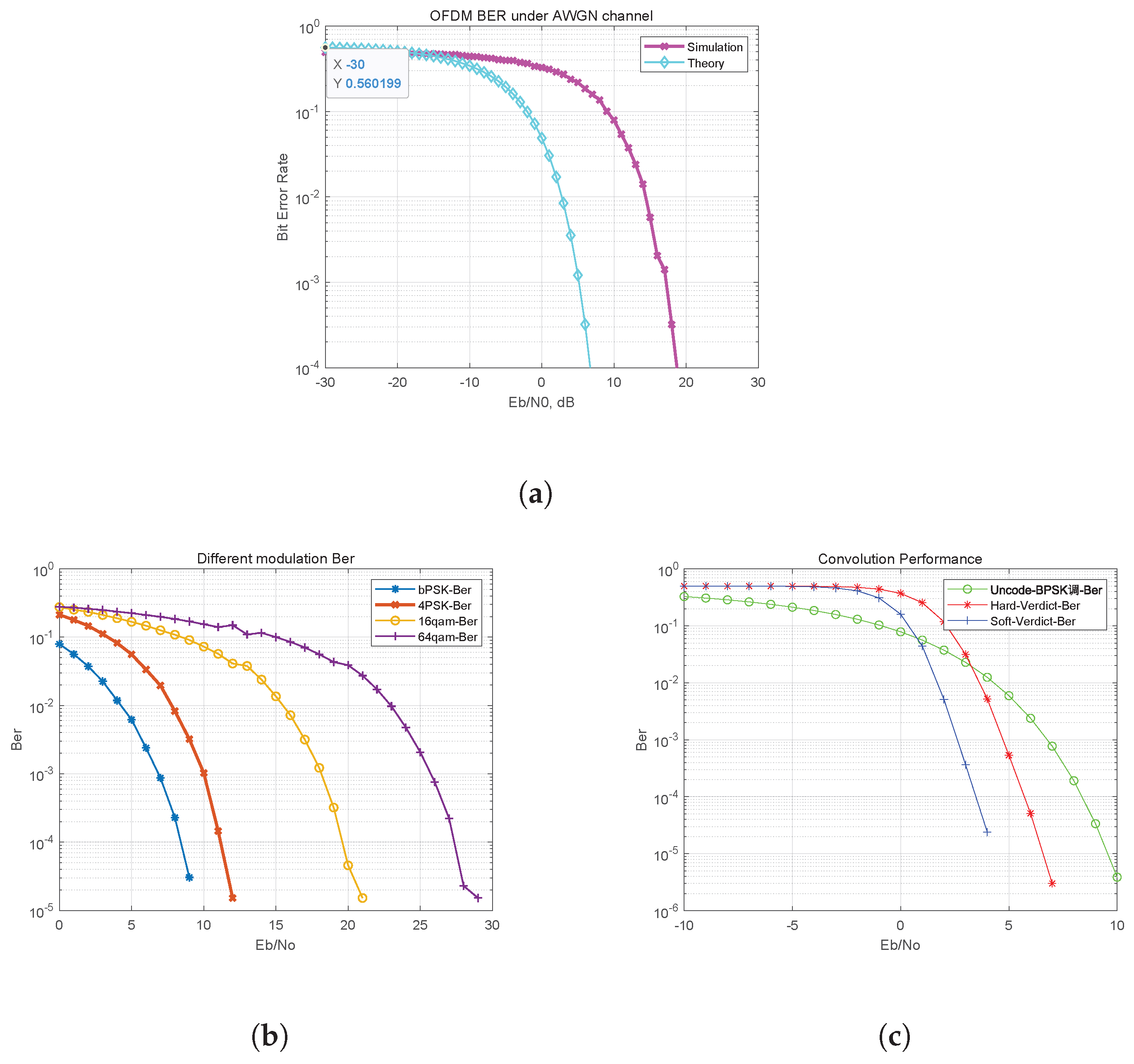
5.1.5. Communication Bit Error Ratio

In this subsection, the communication bit error ratio (BER) performance is evaluated. The BER performance proof is the same as for the traditional OFDM signal in communication. Therefore, this paper will not provide a detailed discussion of the bit error rate (BER) process in OFDM communication [23]. Figure 11a presents the varying error rates corresponding to different modulation methods in OFDM IRCS as the SNR improves, resulting in a lower BER. Figure 11b illustrates a higher BER in complex modulation under noise-free channel conditions. Figure 11c demonstrates the relationship between different demodulation methods and the BER: soft verdict outperforms hard verdict and uncoded BPSK at a high SNR, whereas, at a low SNR, uncoded BPSK performs better than soft verdict and hard verdict.

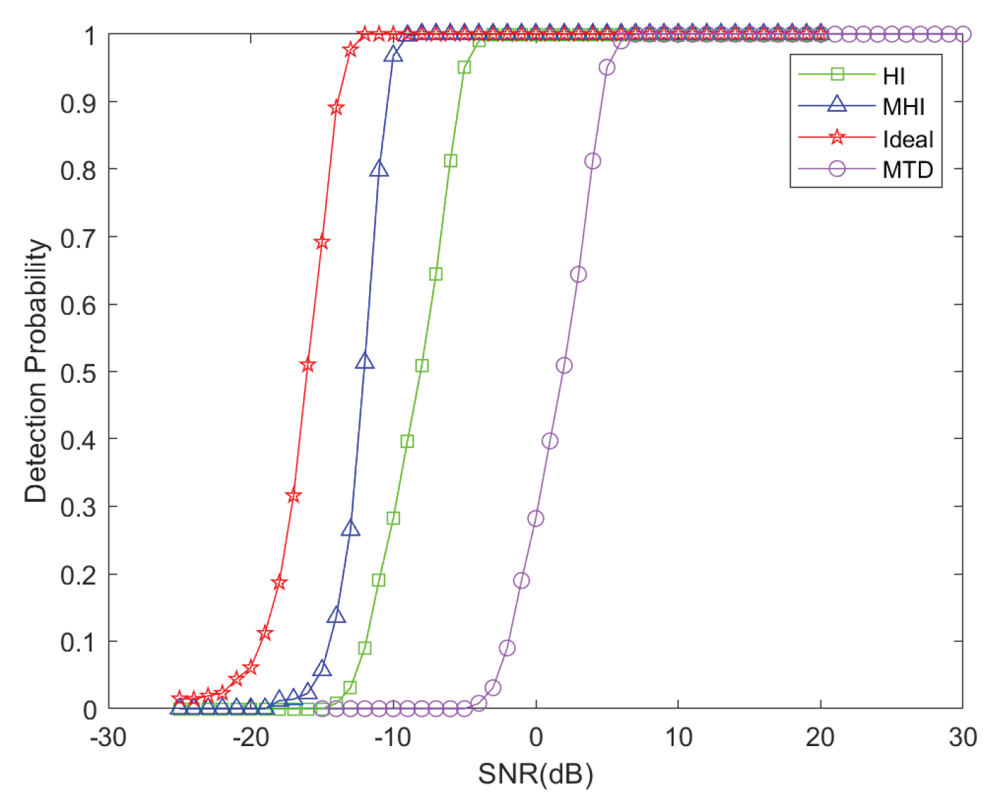
5.1.6. Detection Performance

To demonstrate the robustness of the proposed algorithm, we verify the detection probability of the algorithm using Monte Carlo experiments (10,000 times) with a false alarm rate P f a = 10 4 . The target parameters are consistent with those described in the preceding section. Given the rarity of integration algorithms in OFDM signals, we compare MTD and HI with the proposed method. The results are illustrated in Figure 12.
Compared to multi-frame integration, the proposed method achieves an approximately 4.5 dB higher SNR improvement for a detection probability of 0.9 . This enhancement arises from the proposed method’s hybrid coherent and noncoherent integration across subfragments, which yields superior SNR gains despite the similar intra-frame and inter-frame operations shared with multi-frame integration. In contrast to MTD, which employs only intra-frame coherent integration and integration across entire frames, the proposed method achieves an approximately 7.5 dB higher SNR improvement for a detection probability of 0.9. This improvement is attributed to the proposed method’s ability to mitigate range inconsistencies across the entire integration.

5.1.7. Computation Complexity

Additionally, Figure 13 illustrates the computational complexity of the proposed method compared to MTD and HI. It is observed that as the length of the subfragment increases, the computational complexity of the proposed method exceeds that of the other methods. By comparing the results, it is shown that the proposed method strikes a balance between the detection performance and computational efficiency.

6. Conclusions

This paper proposes a novel modified hybrid integration method for the detection of moving weak targets in a DFRC OFDM system. The method achieves coherent integration within subfragments and incoherent integration across different fragments. Initially, the proposed method combines intra-frame and inter-frame integration within a single subfragment. Subsequently, leveraging the output characteristics of these subfragments, the GRT is applied between different subfragments. This paper provides detailed derivations and analyses of the proposed method across three key aspects: the integration output response, probability of detection, and communication performance. Finally, we have adapted traditional radar signal processing algorithms into OFDM IRCS signals and describe comprehensive numerical experiments to validate the theoretical derivations and analyses. The results demonstrate that, without increasing the computational load, the proposed method can effectively improve the detection probability, thereby enabling the better detection of weak maneuvering targets.

Author Contributions

Methodology, W.J.; Software, W.J.; Writing—original draft, W.J. and N.Z.; Writing—review & editing, W.J., T.L., Y.S. and H.Y.; Visualization, W.J.; Supervision, B.T.; Project administration, B.T.; Funding acquisition, B.T. All authors have read and agreed to the published version of the manuscript.

Funding

This research received no external funding.

Data Availability Statement

No new data were created or analyzed in this study. Data sharing is not applicable to this article.

Conflicts of Interest

The authors declare no conflict of interest.

References

  1. Trees, H. Detection, Estimation, and Modulation Theory, Part I: Detection, Estimation, and Linear Modulation Theory; Wiley: Hoboken, NJ, USA, 1968. [Google Scholar]
  2. Stiglitz, M. Radar Handbook, 2nd ed.; McGraw-Hill Professional: New York, NY, USA, 1990. [Google Scholar]
  3. Skolnik, M.I. Introduction to Radar Systems/m.i. Skolnik; Mcgraw Hill Electrical Engineering: New York, NY, USA, 2002. [Google Scholar]
  4. HINEDI. Digital Communications—1e; HINEDI: Fall River, MA, USA, 2000. [Google Scholar]
  5. Tavik, G.C.; Olin, I.D. The advanced multifunction rf concept. IEEE Trans. Microw. Theory Tech. 2005, 53, 1009–1020. [Google Scholar] [CrossRef]
  6. Han, L.; Wu, K. Multifunctional transceiver for future intelligent transportation systems. IEEE Trans. Microw. Theory Tech. 2011, 59, 1879–1892. [Google Scholar] [CrossRef]
  7. Moghaddasi, J.; Wu, K. Multifunctional transceiver for future radar sensing and radio communicating data-fusion platform. IEEE Access 2016, 4, 818–838. [Google Scholar] [CrossRef]
  8. Sturm, C.; Wiesbeck, W. Waveform design and signal processing aspects for fusion of wireless communications and radar sensing. Proc. IEEE 2011, 99, 1236–1259. [Google Scholar] [CrossRef]
  9. Sit, Y.L.; Nuss, B.; Zwick, T. On mutual interference cancellation in a mimo ofdm multiuser radar-communication network. IEEE Trans. Veh. Technol. 2018, 67, 3339–3348. [Google Scholar] [CrossRef]
  10. Liu, Y.; Liao, G.; Yang, Z.; Xu, J. Design of integrated radar and communication system based on mimo-ofdm waveform. J. Syst. Eng. Electron. 2017, 28, 669–680. [Google Scholar]
  11. Liu, Y.; Liao, G.; Xu, J.; Yang, Z.; Zhang, Y. Adaptive ofdm integrated radar and communications waveform design based on information theory. IEEE Commun. Lett. 2017, 21, 2174–2177. [Google Scholar] [CrossRef]
  12. Liu, Y. Transmit power adaptation for orthogonal frequency division multiplexing integrated radar and communication systems. J. Appl. Remote Sens. 2017, 11, 1. [Google Scholar] [CrossRef]
  13. Liao, G.; Liu, Y.; Yang, Z. Robust ofdm integrated radar and communications waveform design based on information theory. Signal Process. 2018, 162, 317–329. [Google Scholar] [CrossRef]
  14. Liu, Y.; Yang, Z.; Liao, G.; Xu, J. Multiobjective optimal waveform design for ofdm integrated radar and communication systems. Signal Process. Off. Publ. Eur. Signal Process. (EURASIP) 2017, 141, 331–342. [Google Scholar] [CrossRef]
  15. Liu, J.; Xu, Z. Joint range and angle estimation for an integrated system combining mimo radar with ofdm communication. Multidimens. Signal Process. 2019, 30, 2. [Google Scholar] [CrossRef]
  16. Liu, Y. Range and angle estimation for mimo-ofdm integrated radar and communication systems. In Proceedings of the 2016 CIE International Conference on Radar (RADAR), Guangzhou, China, 10–13 October 2016. [Google Scholar]
  17. Chiriyath, A.R.; Ragi, S.; Mittelmann, H.D.; Bliss, D.W. Novel radar waveform optimization for a cooperative radar-communications system. IEEE Trans. Aerosp. Electron. Syst. 2019, 55, 1160–1173. [Google Scholar] [CrossRef]
  18. Hassanien, A.; Amin, M.G.; Zhang, Y.D.; Ahmad, F. Signaling strategies for dual-function radar communications: An overview. IEEE Aerosp. Electron. Syst. Mag. 2016, 31, 36–45. [Google Scholar] [CrossRef]
  19. Takase, H.; Shinriki, M. Dual-function radar-communications: Information embedding using sidelobe control and waveform diversity. IEEE Trans. Signal Process. 2016, 64, 2168–2181. [Google Scholar]
  20. Takase, H.; Shinriki, M. A dual-use radar and communication system with complete complementary codes. In Proceedings of the 2014 15th International Radar Symposium (IRS), Gdansk, Poland, 16–18 June 2014. [Google Scholar]
  21. Romero, R.A.; Shepherd, K.D. Friendly spectrally shaped radar waveform with legacy communication systems for shared access and spectrum management. IEEE Access 2015, 3, 1541–1554. [Google Scholar] [CrossRef]
  22. Guan, Y.; Dai, Y.; Zhang, W.; Lin, D.; He, D. Dtmb application in shanghai sfn transmission network. IEEE Trans. Broadcast. 2013, 59, 183–187. [Google Scholar] [CrossRef]
  23. Zheng, Z.W. Effects of power amplifier distortion and channel estimation errors on the performance of dvb-h system with multiple-antenna receiver. IEEE Trans. Consum. Electron. 2009, 55, 1810–1818. [Google Scholar] [CrossRef]
  24. Welch, G.; Bishop, G.; Union, E.B.; Committee, L.S.I. Tr 101 190—v1.3.2—Digital Video Broadcasting (dvb); Implementation Guidelines for dvb Terrestrial Services; Transmission Aspects; ETSI: Valbonne, France, 2003. [Google Scholar]
  25. Huang, J.; Presti, L.; Garello, R. Digital video broadcast-terrestrial (dvb-t) single frequency networks positioning in dynamic scenarios. Sensors 2013, 13, 10191–10218. [Google Scholar] [CrossRef]
  26. IEEE. Wireless lan medium access control (mac) and physical layer (phy) specifications; high-speed physical layer in the 5ghz band. In IEEE 802.11a-Part 11; IEEE: Piscataway Township, NJ, USA, 1999. [Google Scholar]
  27. Afaqui, M.S.; Garcia-Villegas, E.; Lopez-Aguilera, E. Ieee 802.11ax: Challenges and requirements for future high efficiency wifi. In IEEE Wireless Communications; IEEE: Piscataway Township, NJ, USA, 2016; pp. 130–137. [Google Scholar]
  28. Zhang, T.; Xia, X.G.; Kong, L. Irci free range reconstruction for sar imaging with arbitrary length ofdm pulse. IEEE Trans. Signal Process. 2014, 62, 4748–4759. [Google Scholar] [CrossRef]
  29. Sen, S. Ofdm radar space-time adaptive processing by exploiting spatio-temporal sparsity. IEEE Trans. Signal Process. 2013, 61, 118–130. [Google Scholar] [CrossRef]
  30. Sen, S.; Nehorai, A. Sparsity-based multi-target tracking using ofdm radar. IEEE Trans. Signal Process. 2011, 59, 1902–1906. [Google Scholar] [CrossRef]
  31. Yl, A.; Rsb, B.; Gl, A.; Sz, A. Passive mimo radar detection exploiting known format of the communication signal observed in colored noise with unknown covariance matrix. Signal Process. 2020, 174, 107611. [Google Scholar]
  32. Liu, Y.; Liao, G.; Xu, J.; Yang, Z.; Yin, Y. Improving detection performance of passive mimo radar by exploiting the preamble information of communications signal. IEEE Syst. J. 2020, 15, 4391–4402. [Google Scholar] [CrossRef]
  33. Liu, Y.J.; Liao, G.S.; Yang, Z.W. Ambiguity function analysis of integrated radar and communication waveform based on ofdm. Syst. Eng. Electron. 2016, 38, 2008–2018. [Google Scholar]
  34. Li, X.; Cui, G.; Wei, Y.; Kong, L. Fast coherent integration for maneuvering target with high-order range migration via trt-skt-lvd. IEEE Trans. Aerosp. Electron. Syst. 2016, 52, 2803–2814. [Google Scholar] [CrossRef]
  35. Li, X.; Sun, Z.; Yeo, T.S. Computational efficient refocusing and estimation method for radar moving target with unknown time information. IEEE Trans. Comput. Imaging 2020, 6, 544–557. [Google Scholar] [CrossRef]
  36. Li, X.; Cui, G.; Yi, W.; Kong, L.J. Coherent integration for maneuvering target detection based on radon-lv’s distribution. IEEE Signal Process. Lett. 2015, 22, 1467–1471. [Google Scholar] [CrossRef]
  37. Tian, J.; Xia, X.; Cui, W.; Yang, G.; Wu, S. A coherent integration method via radon-nufrft for random pri radar. IEEE Trans. Aerosp. Electron. Syst. 2017, 53, 2101–2109. [Google Scholar] [CrossRef]
  38. Wang, J.; Wei, Y.; Kirubarajan, T.; Kong, L. An efficient recursive multiframe track-before-detect algorithm. IEEE Trans. Aerosp. Electron. Syst. 2018, 54, 190–204. [Google Scholar] [CrossRef]
  39. Carlson, B.D.; Evans, E.D.; Wilson, S.L. Search radar detection and track with the hough transform, part i: System concept. IEEE Trans. Aerosp. Electron. Syst. 1994, 30, 102–108. [Google Scholar] [CrossRef]
  40. Carlson, B.D.; Wilson, E.S.L.; Lincoln, M. Search radar detection and track with the hough transform part ii: Detection statistics vans, member, ieeb. IEEE Trans. Aerosp. Electron. Syst. 2002, 30, 109–115. [Google Scholar] [CrossRef]
  41. Perry, R.P.; Dipietro, R.C.; Fante, R.L. Sar imaging of moving targets. IEEE Trans. Aerosp. Electron. Syst. 1999, 35, 188–200. [Google Scholar] [CrossRef]
  42. Perry, R.P.; Dipietro, R.C.; Fante, R.L. Coherent integration with range migration using keystone formatting. In Proceedings of the 2007 IEEE Radar Conference, Waltham, MA, USA, 17–20 April 2007. [Google Scholar]
  43. Xu, J.; Yu, J.; Peng, Y.; Xia, X. Radon-fourier transform for radar target detection, i: Generalized doppler filter bank. IEEE Trans. Aerosp. Electron. Syst. 2011, 47, 1186–1202. [Google Scholar] [CrossRef]
  44. Xu, J.; Yu, J.; Peng, Y.N.; Xia, X.G. Radon-fourier transform for radar target detection (ii): Blind speed sidelobe suppression. IEEE Trans. Aerosp. Electron. Syst. 2011, 47, 2473–2489. [Google Scholar] [CrossRef]
  45. Ji, Y.; Jia, X.; Peng, Y.N.; Xia, X.G. Radon-fourier transform for radar target detection (iii): Optimality and fast implementations. IEEE Trans. Aerosp. Electron. Syst. 2012, 48, 991–1004. [Google Scholar]
  46. Xu, J.; Yu, J.; Peng, Y.N.; Xia, X.G.; Long, T. Space-time radon-fourier transform and applications in radar target detection. Radar Sonar Navig. Iet 2012, 6, 846–857. [Google Scholar] [CrossRef]
  47. Xu, J.; Xia, X.G.; Peng, S.B.; Yu, J.; Peng, Y.N.; Qian, L.C. Radar maneuvering target motion estimation based on generalized radon-fourier transform. IEEE Trans. Signal Process. 2012, 60, 6190–6201. [Google Scholar]
  48. IEEE. IEEE 802.16m Technology Introduction, White Paper; IEEE: Piscataway Township, NJ, USA, 2011. [Google Scholar]
  49. Jiang, D. Ieee 802.11p: Towards an international standard for wireless access in vehicular environments. In Proceedings of the VTC Spring 2008—IEEE Vehicular Technology Conference, Marina Bay, Singapore, 11–14 May 2008. [Google Scholar]
  50. IEEE. Wireless lan medium access control (mac) and physical layer (phy) specifications: Amendment 5: Enhancements for higher throughput. In The Editors of IEEE802.11; IEEE: Piscataway Township, NJ, USA, 1997. [Google Scholar]
  51. Kumari, P.; Choi, J.; González-Prelcic, N.; Heath, R.W. Ieee 802.11ad-based radar: An approach to joint vehicular communication-radar system. IEEE Trans. Veh. Technol. 2017, 67, 3012–3027. [Google Scholar] [CrossRef]
  52. Kay, S. Fundamentals of Statistical Signal Processing, Volume II: Detection Theory; Pearson Education: New York, NY, USA, 1993. [Google Scholar]
Figure 1. Detailed processing flowchart of the MHI.
Remotesensing 16 03601 g001
Figure 2. Sketch map of the flowchart for intra-frame integration.
Remotesensing 16 03601 g002
Figure 3. Sketch map of the flowchart for inter-frame integration.
Remotesensing 16 03601 g003
Figure 4. Modified GRT integration path.
Remotesensing 16 03601 g004
Figure 5. Intra-frame integration results. (a) Range across echo, (b) intra-frame integration, (c) one frame integration result of a single target, (d) the distance slice of (c), (e) the Doppler slice of (d).
Remotesensing 16 03601 g005
Figure 6. Single target results for ( S N R = 20 dB). (a) MTD results, (b) HI integration results, (c) proposed method’s result.
Remotesensing 16 03601 g006
Figure 7. Single target results for ( S N R = 20 dB). (a) MTD result, (b) HI integration result, (c) proposed method’s result.
Remotesensing 16 03601 g007
Figure 8. Simulation results for multiple targets (scenario 1). (a) Multiple-target echo distribution, (b) integration result on velocity–range plane, (c) integration result on range–acceleration plane, (d) integration result on velocity–acceleration plane.
Remotesensing 16 03601 g008
Figure 9. Simulation results for multiple targets (scenario 2). (a) Multiple-target echo distribution, (b) integration result on velocity–range plane, (c) integration result on range–acceleration plane, (d) integration result on velocity–acceleration plane.
Remotesensing 16 03601 g009
Figure 10. Simulation results for multiple targets (scenario 3). (a) Multiple-target echo distribution, (b) integration result on velocity–range plane, (c) integration result on range–acceleration plane, (d) integration result on velocity–acceleration plane.
Remotesensing 16 03601 g010
Figure 11. Communication BER results. (a) OFDM IRCS BER with AWGN, (b) BER with different modulation methods, (c) BER with different demodulation methods.
Remotesensing 16 03601 g011
Figure 12. Detection probabilities of different methods.
Remotesensing 16 03601 g012
Figure 13. Computational complexity of different methods.
Remotesensing 16 03601 g013
Table 1. A comparison between MTD, HI, and MHI.
MethodAll Complexity (Flops)
MHI1.9 × 10 4 Flops
HI6 × 10 5 Flops
MTD1.2 × 10 4 Flops
Table 2. Parameter design.
ParameterValue
Carrier frequency3 GHz
Number of subcarriers512
Elementary OFDM symbol duration0.1 ms
Subcarrier spacing10 kHz
Cyclic prefix length0.025 ms
Total OFDM symbol duration0.125 ms
Total signal bandwidth5.12 MHz
Radar range resolution30 m
Unambiguous range15 km
Unambiguous velocity[−800 m/s, 800 m/s]
Velocity resolution1.55 m/s
Radar PRI100
Subfragment length40 pulses
Disclaimer/Publisher’s Note: The statements, opinions and data contained in all publications are solely those of the individual author(s) and contributor(s) and not of MDPI and/or the editor(s). MDPI and/or the editor(s) disclaim responsibility for any injury to people or property resulting from any ideas, methods, instructions or products referred to in the content.

