Article

Methods for Assessing the Effectiveness of Modern Counter Unmanned Aircraft Systems

by
Konrad D. Brewczyński
1,*,
Marek Życzkowski
1,
Krzysztof Cichulski
1,
Kamil A. Kamiński
1,
Paraskevi Petsioti
2 and
Geert De Cubber
3
1
Institute of Optoelectronics, Military University of Technology, ul. gen. Sylwestra Kaliskiego 2, 00-908 Warsaw, Poland
2
Center for Security Studies, P. Kanellopoulou 4, 101 77 Athens, Greece
3
Royal Military Academy of Belgium, Robotics & Autonomous Systems Unit, 30 Av. De La Renaissance, 1000 Brussels, Belgium
*
Author to whom correspondence should be addressed.
Remote Sens. 2024, 16(19), 3714; https://doi.org/10.3390/rs16193714 (registering DOI)
Submission received: 21 August 2024 / Revised: 2 October 2024 / Accepted: 4 October 2024 / Published: 6 October 2024
(This article belongs to the Special Issue Drone Remote Sensing II)

Abstract

:
Given the growing threat posed by the widespread availability of unmanned aircraft systems (UASs), which can be utilised for various unlawful activities, the need for a standardised method to evaluate the effectiveness of systems capable of detecting, tracking, and identifying (DTI) these devices has become increasingly urgent. This article draws upon research conducted under the European project COURAGEOUS, where 260 existing drone detection systems were analysed, and a methodology was developed for assessing the suitability of C-UASs in relation to specific threat scenarios. The article provides an overview of the most commonly employed technologies in C-UASs, such as radars, visible light cameras, thermal imaging cameras, laser range finders (lidars), and acoustic sensors. It explores the advantages and limitations of each technology, highlighting their reliance on different physical principles, and also briefly touches upon the legal implications associated with their deployment. The article presents the research framework and provides a structural description, alongside the functional and performance requirements, as well as the defined metrics. Furthermore, the methodology for testing the usability and effectiveness of individual C-UAS technologies in addressing specific threat scenarios is elaborated. Lastly, the article offers a concise list of prospective research directions concerning the analysis and evaluation of these technologies.

1. Introduction

In recent years, there has been an exponential increase in the use of drones. Typically used for leisure and entertainment, civilians have adopted this technology for many activities [1]. Due to project conditions and manufacturer requests, the full source material is confidential; therefore, only a synthesised analysis is presented in this article. However, for the last decade, there have been multiple reports on the use of drones for malicious intent [2,3]. As a result of these incidents, the private sector partnered with academia and concluded that there was a need to protect critical infrastructures with dedicated C-UASs. This idea is relatively new, so there is no consensus on the requirements for producing and testing such systems [4]. This article attempts to systematise and standardise anti-drone system approaches and analyse their effectiveness so that any critical infrastructure unit can decide which system is most suitable for its environment.
After a review of the solutions available on the market for detecting, tracking, and identifying (DTI) drones, a summary database of companies and their systems’ solutions was created. This database was used to analyse the following parameters for the available technologies: ranges; fields of view (in elevation and azimuth); the frequencies they use; whether these technologies are omnidirectional or consider the number of sectors covered by the technology’s field of view; whether the system detects the drone, its operator, or the communication between them; whether the system is equipped with artificial intelligence; or whether it can learn in a new given environment, etc. In addition, the operational parameters of the systems are also given, such as the mobility of the system (whether it is fixed, mobile, handheld, or automotive), whether it contains the control software, the type of power supply, the possibility of extending a given system with other technologies, the number of operators necessary to operate it, the difficulty of using the user interface, or the time needed to set up the equipment.
Due to the many types of sensors used in C-UASs, and the lack of specific requirements and the related methods of measuring the range and quality of devices, the selection of a given technology for a specific application presents a significant challenge [5]. A particularly important element is the lack of the described methods of measurement and measured parameters of C-UASs, which would make it possible to compare different technologies. It is also possible to use several different technologies in one solution, which further complicates the situation. Therefore, this article is an attempt to enumerate the advantages and disadvantages of all technologies and their combinations, in order to develop comparative metrics for C-UAS solutions. This article also serves as an introduction to proposing a methodology for conducting field tests on the selected C-UAS solutions as it indicates the limitations resulting from the physical basis of the technology as well as the limitations resulting from its design and usability.
As part of the project, we conducted a series of tests in four countries: Romania, Greece, Belgium, and Spain. The testing process was organised in an iterative and agile manner, which allowed for the continuous improvement of procedures and adaptation to changing conditions and results obtained at various stages.
The tests were carried out in accordance with specific testing frameworks, which ensured the consistency and comparability of the results obtained. Within each testing cycle, we analysed the results, identified areas requiring improvement, and implemented the appropriate adjustments to the testing methodology. This made the process dynamic and flexible, enabling effective responses to new challenges and contextual changes. The tests carried out under the COURAGEOUS project were intended to verify whether the developed methodology was correct. If any uncertainties arose during the tests, they served to prompt adjustments to the methodology. Those tests were not intended to identify the best technical solution or to rank any C-UASs.
Before commencement, it was necessary to plan the subsequent days of testing, including all the functions to be distributed among consortium partners. The selection of test scenarios in each country and its respective infrastructure was also crucial. At this stage, we needed to plan the drone flight paths, decide whether they would be operated by pilots or fly autonomously, determine the flight altitudes and speeds, etc. Subsequently, we could send invitations to the selected companies producing C-UAS solutions. We aimed to invite companies to test the widest variety of C-UAS technologies and their diverse combinations rather than focusing on a single ready-made solution. Additionally, we tested technologies, not integrating software; hence, companies that did not produce their own hardware solutions were not considered as standalone systems (but as components of larger consortia). The next step involved conducting surveys among end users (LEAs) about their expectations regarding the test procedures. Once a sufficient number of C-UASs had been submitted, we could proceed with deploying the systems near the test centre infrastructure. One of the major challenges was deciding how to test several different systems simultaneously. Sequential testing—one after another—would not guarantee identical weather conditions, drone flights, or test durations for all systems, leading to non-reproducible tests. We opted for the parallel testing of C-UASs. Therefore, we needed to ensure that the systems did not interfere with each other, which is why we conducted all-day electromagnetic background measurements at the test site. Each C-UAS was monitored by a LEA representative who recorded the moments of detection and the tracking of drones by the system. All detections and traces were additionally recorded by each company for later analysis. After the tests, the results were discussed, and then the actual drone flight paths were mapped and compared to what the C-UASs had shown. The actual drone paths were known thanks to GPS trackers attached to each launched drone. The above research framework is presented in Figure 1.
The tests involved 46 drones, representing 20 different companies, which ensured a broad spectrum of technologies and solutions. In total, these drones conducted approximately 180 flight missions. The study evaluated 24 C-UASs, allowing for an analysis of various methods for detecting, tracking, and drone identifying. Among these systems, three were tested in more than one country, providing data on their effectiveness in different conditions and usage scenarios. This extensive scale of testing provided significant insights on the current technologies.

2. Definitions in the C-UAS Framework

In order to better understand the content of the following sections of this article, it is necessary to systematise the understanding of the terms used in it. These terms are defined below.
Detection (D of DTI): detection is a basic C-UAS functionality. The task of the system is to detect a UAS (drone) in a specific space near the protected facility or area. UAS detection systems can be fixed, mobile, or portable, depending on the needs of the services responsible for security and the adopted threat scenarios. Various technologies are used for detection, as described in this article [6].
Tracking (T of DTI): when a UAS has been detected, the C-UAS may be able to track it, i.e., determine the path along which the UAS is moving and where it exactly is at the present moment. The ability to track the UAS allows the system operator and the services responsible for security to assess the situation on an ongoing basis and take action appropriate to a threat.
Identification (I of DTI): some of the technologies used in the C-UAS for some types of UASs (drones), most often the most popular ones produced in large series, have the potential to recognise the model. Such information allows one to determine the capabilities of the device, e.g., flight time and speed, and is extremely important from the point of view of the services responsible for security. In some cases, by listening to the transmission between the UAS and the pilot, it is possible to obtain information about the battery charge status, flight speed and direction, and the location of the pilot [6].
Microwave radar (R): a radiolocation system that uses radio waves (here, microwaves) to determine the distance (ranging), angle (azimuth), and radial velocity of objects relative to the site. It is used to detect and track drones (UAS). A radar system consists of a transmitter producing microwaves, a transmitting antenna, a receiving antenna (generally, the same antenna is used for transmitting and receiving), a receiver, and a processor to determine the properties of the objects. Radio waves (pulsed or continuous) from the transmitter reflect off the objects and return to the receiver, providing information about the object’s location and speed [7].
Visible light camera (V): a device that converts light visible to humans into electrical pulses that make it possible to record, display, and analyse the image observed by the camera.
Thermal imaging camera (T): a device that converts thermal radiation into electrical impulses that make it possible to record, display, and analyse the image observed by the camera. The image displayed based on the signal received from the thermal imaging camera is most often presented in black and white, where the appropriate degrees of grey colour correspond to the appropriate temperature of the observed object.
Infrared sensor (I): a detector operating in the range of thermal radiation that signals a change in the average temperature of the observed area. For the purposes of this article, systems using thermal imaging cameras to generate an alarm are also treated as an infrared detector, where the observation function is treated as secondary to the object detection function.
Lidar (L): an acronym that stands for “light detection and ranging”, this is a method for determining ranges by targeting an object or a surface with a laser and measuring the time for the reflected light to return to the receiver. This article describes lidars as laser rangefinders.
Frequency-monitoring device (F): a device that allows one to detect and listen to communication between the pilot and the UAS. It is possible to track the position of the UAS based on the triangulation of the received radio signal, and sometimes the position of the pilot as well. Some of the devices allow one to decode the signal sent by the UAS and read its position based on data from the GPS receiver installed on the drone [6].
Acoustic sensor (A): a device that uses sensitive directional microphones for its operation. The acoustic wave received by them is analysed in terms of the presence of sounds that are characteristic of drone rotors. It allows one to detect the UAS and determine the direction from which it is coming [6].
The authors conducted tests of C-UASs in accordance with the structural description of basic research. The basic research framework used in this article has a slightly modified order, as its core is the discussion of C-UAS technologies and the testing methodologies implemented within the COURAGEOUS project. To enhance the readability of the article, Figure 2 presents the structural framework of the basic research, indicating where each stage appears in this paper.

3. Technologies

This section presents a detailed analysis of C-UASs that were verified within the COURAGEOUS project. It begins with an overview of the selection process for C-UASs chosen for further testing, as well as the challenges faced by analysts during data collection. Furthermore, it provides a compilation of the most commonly used technologies in C-UASs, along with the physical limitations affecting the reduced applicability of individual technologies under specific conditions. Subsequently, this section outlines the most commonly used methods for integrating C-UASs with external systems, often utilising dedicated transmission protocols to reduce the number of transmitted data while simultaneously achieving system objectives. The collected database of C-UASs was then analysed for mobility, which can be a crucial aspect for military applications. As described in the latter part of this section, the authors conducted a detailed correlational analysis of the applied C-UAS technologies. This stems from the fact that the most accurate systems typically utilise information from multiple sensors of different technologies, allowing for information confirmation in another spectrum of signal analysis, thus increasing system sensitivity and filtering out false alarms. Artificial intelligence is often employed for this purpose. This section concludes with an analysis of the legal aspects of drone detection concerning the applied technologies.

3.1. Evaluation of Selected DTI Technologies and DTI Systems Based on Fundamental Technical Parameters

In UAS detection, tracking, and identification systems, various technologies are employed, whose usefulness in C-UASs can be evaluated based on their technical parameters. In the following text, it will be demonstrated that an assessment based solely on fundamental technical data may not always be applicable for determining the suitability of a given system in a specific scenario for an object existing in real-world conditions. Environmental factors such as the location of the object and its surroundings, climate and weather conditions, and the level of electromagnetic interference significantly impact the utility of a given technical solution in C-UASs.
The most commonly used solution for detecting, tracking, and identifying UASs is radar. These systems operate using microwave frequencies. Typically, the assessment of radar suitability for UAS detection considers the following parameters:
  • Operating frequency (wavelength)—this is a crucial parameter, especially when detecting small objects like UASs. Higher frequencies allow for the detection of smaller objects. When the size of the object is smaller than the wavelength, Rayleigh scattering occurs, and the detection efficiency significantly decreases as the size of the detected object diminishes. It should be noted that for the frequencies most used in radars for UAS detection, 10 GHz, the wavelength is 0.3 m. Conversely, higher frequencies are more heavily attenuated in the atmosphere by rain, fog, and snow, which limit the effective range of radars due to a reduction in reflected signal power.
  • Radar output power—a higher radar power allows for an increased range. According to the equation describing the power of the signal received by the radar in relation to the distance from the object, the power decreases proportionally to the fourth power of the distance. At greater distances, the radar cross-section (RCS) (3 in Table 1), which is a measure of an object’s ability to reflect radar signals, becomes a critical parameter. This coefficient depends, among other factors, on the object’s orientation relative to the radar beam. A smaller reflective surface results in a weaker reflected signal. Most radars are designed to be used without special permission. To achieve this, radars must operate within legally specified frequencies and the corresponding maximum powers. Using radars outside these legal limits requires the user to obtain permission and pay for the use of the radio spectrum.
  • Receiver sensitivity—this parameter allows for the radar’s range to be extended and detect more distant objects.
In addition to the above fundamental technical parameters influencing the ability to detect UAVs, parameters specific to the given technology are also important. Radars commonly use two technologies: pulsed radars, which emit short, intense pulses of electromagnetic waves, and Frequency Modulated Continuous Wave (FMCW) radars.
Characteristics of pulsed radars include pulse duration (a shorter pulse duration allows for a more accurate determination of object distance), dynamic range (a greater dynamic range enables the detection of objects of various sizes and at different distances), time resolution (a higher time resolution allows for more precise distance measurement), and pulse power (a higher pulse power enables object detection at greater distances).
For FMCW radars, a key characteristic parameter is the frequency modulation range (a wider modulation range allows for more accurate distance measurement but can complicate precise speed measurement, as modulation may mask small frequency shifts caused by the Doppler effect when the object is in motion), which affects distance resolution.
Both the above-mentioned radar technologies have their advantages and disadvantages, and the assessment of the suitability of a given technology based on its technical parameters may be prone to error due to the obstacles present on the real object and variable weather conditions.
Detection systems also utilise visible light and infrared observation systems to detect UASs.
The use of visible light cameras is significantly limited. The primary limitation is that a camera requires a light source for observation. Therefore, their use is essentially restricted to daylight hours when sunlight is present. As light intensity decreases, the usefulness of such cameras drops significantly (4 in Table 1). Key parameters for a visible light camera used in UAS detection include sensitivity (a higher sensitivity allows for detecting objects in lower light conditions), resolution (a higher camera resolution enables the detection, tracking, and identification of smaller objects but depends on the lens parameters used; it is also worth noting that a higher resolution generally comes with smaller pixel sizes on the detector, which directly impacts the camera’s sensitivity), electronic shutter speed (a shorter shutter speed results in clearer images of fast-moving objects but also reduces the amount of light reaching the detector), dynamic range (which affects the ability to distinguish objects of varying brightness), the lens used and its parameters, including focal length (a longer focal length allows for the observation of more distant objects but narrows the field of view (4 in Table 1)), lens aperture (a greater lens aperture increases the overall sensitivity of the camera system), and aperture range (which allows for the adjustment of light reaching the detector and affects the depth of field).
In summary, due to technological limitations, daylight cameras are more often used to verify, track, and identify UASs detected by other technologies rather than for initial detection.
Thermal imaging cameras are significantly more effective for UAS detection than visible light cameras. The average temperature of a clear sky ranges from −60 °C to −40 °C, and in the worst case, with low clouds visible, the average temperature is between −10 °C and 0 °C. The average temperature of a flying drone can range from 20 °C to 80 °C, with motors and batteries always being warmer than other parts. This temperature difference makes detecting, tracking, and often identifying UASs easier with a thermal imaging camera compared to a visible light camera. It should be noted, however, that fog and precipitation will limit the use of thermal cameras in C-UAV systems, though not to the same extent as visible light cameras.
Thermal cameras have specific parameters that can be used to evaluate them. The first characteristic of thermal cameras is the type of sensor. Cameras can use either cooled or uncooled sensors. The type of sensor significantly impacts other camera parameters relevant to use in UAS detection, tracking, and identification systems, such as thermal sensitivity (NETD—noise equivalent temperature difference), spectral range, and resolution. Since the camera is a combination of the sensor and lens, lens parameters are also crucial, so the camera should be analysed as a whole camera system.
A limitation of thermal cameras, similar to visible light cameras, is the restricted field of view. It is possible to detect UAVs from a long distance, but with a long focal length, the field of view narrows considerably (4 in Table 1). Detecting a UAV with a diameter of about 0.3 m from a distance of 2 km requires narrowing the field of view (FOV) to below three degrees. Therefore, thermal cameras are most used in detection, tracking, and observation systems for the latter two tasks when the object has already been detected by other sensors.
An interesting solution is the so-called thermal radar. This device has a rotating head with a thermal camera mounted on it, and the image processing system displays the entire area around it in a 360-degree view. UAV detection is signalled in the system, and the object’s image is enlarged in a separate window. Tests conducted as part of the COURAGEOUS project indicate that these systems are useful for detecting drones at distances from a few hundred meters to about 1 km.
In summary, given that a thermal camera must operate in C-UAV systems as an integrated unit with the lens under variable weather conditions, only actual field tests can determine its usefulness in protecting a specific object or usage scenario.
Acoustic sensors are also used in C-UAV systems. This is an intriguing technology but faces the most challenges in effectively detecting UAVs. Basic parameters of such systems include frequency range, microphone sensitivity, microphone bandwidth, time resolution, listening angle, and signal-to-noise ratio. To effectively detect a flying drone, the system requires advanced acoustic signal processing. Some systems can recognise typical drones by their acoustic signal signature (11 in Table 1). However, these sensors face limitations due to interference from external acoustic sources such as passing cars, street noise, machinery sounds, wind, rain, and reflected sounds.
The effective range of acoustic sensors varies depending on the technology used and the method of acoustic signal analysis, ranging from about 100 m to about 300 m in ideal conditions. In many cases, this distance is too short for security services to take effective action.
Since the performance quality of these sensors depends largely on the environment where they are used, only field tests, rather than technical data, can provide an indication of their actual usefulness for protecting specific objects or events under various scenarios.
Table 1 presents a subjective assessment of the technologies without delving into the specifics of individual technological solutions. This assessment is supported by the extensive experience of the authors, gained during the tests conducted within the COURAGEOUS project and beyond.
A multi-attribute comparison of technologies is an appropriate approach in most standard studies. However, in the case of C-UAS technologies, which are to be installed in various critical infrastructures and used in different scenarios, this approach becomes less effective. It could be used if only one scenario and one critical infrastructure to be protected against unauthorised drone use were considered. However, such an approach would lose its universality and could not be applied to other scenarios or infrastructures. The main goal of the COURAGEOUS project is to provide a universal evaluation of C-UASs, regardless of the technology used.

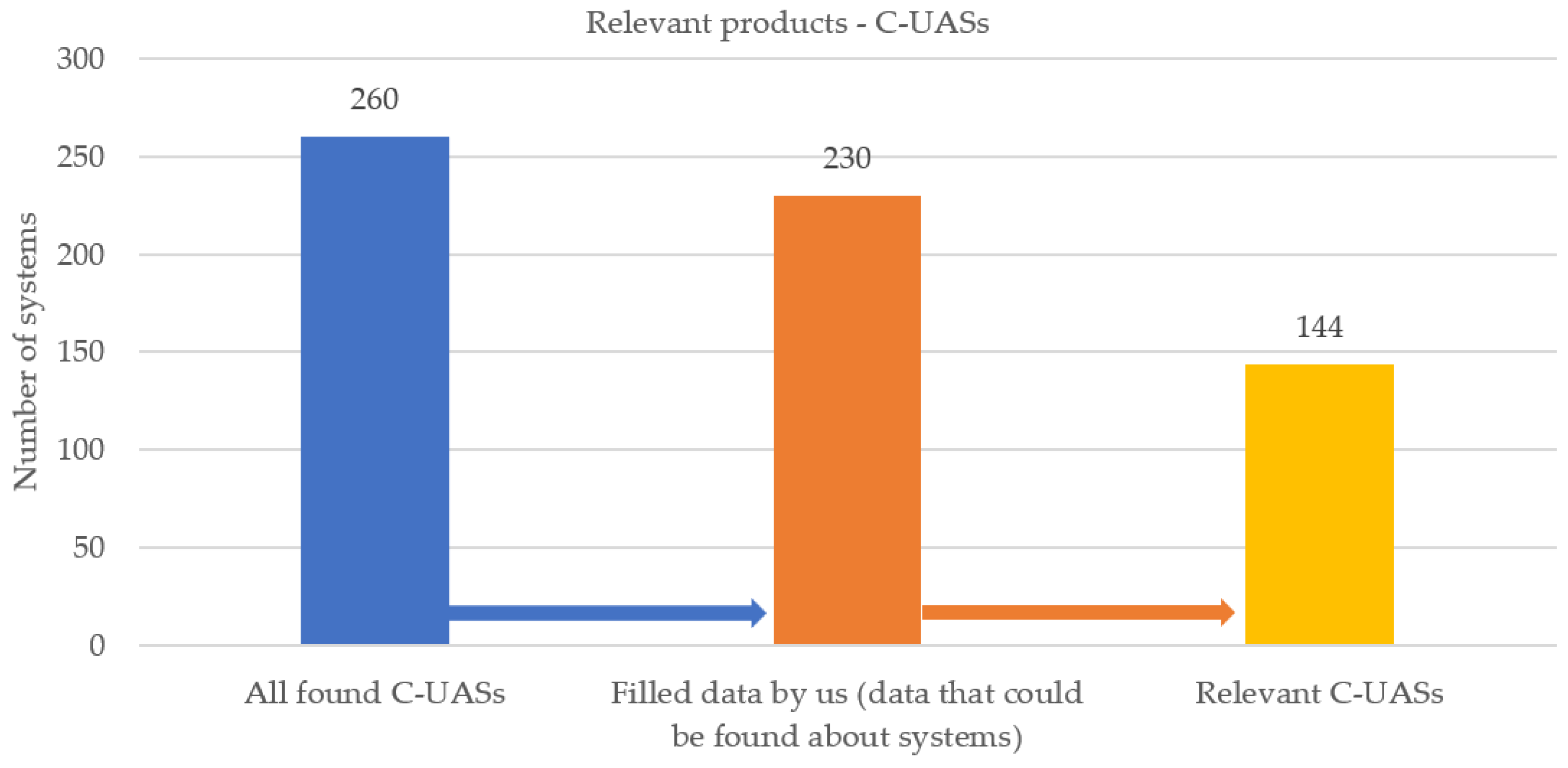
3.2. Relevant Products

During the C-UAS survey, information on 260 anti-drone systems was initially collected. The market research and analysis of available materials showed that some information is no longer valid. Many companies no longer run their websites or have completely ceased to exist. Many products are no longer offered or converted to other product types and marked accordingly with a different trade name. This resulted in 30 disappeared systems no longer being available for purchase. The main factors behind such a significant change over two years on the C-UAS market are as follows:
  • Technological changes in detection solutions;
  • A termination of cooperation with technology suppliers in the case of multi-technology systems, as an economic and competitive factor in the market;
  • Market verification of the offered solutions;
  • The impact of the COVID-19 pandemic on the development of mainly small technology spin-offs.
A summary of the identified C-UAS solutions is shown in Figure 3. In total, 260 systems were found, but the data of 30 systems were not filled. Of the relevant C-UAS solutions from 230 systems with data that were filled, 86 systems were not relevant (the “not relevant systems” are those that were only software for DTI systems of other manufacturers, devices disrupting the transmission between the pilot and the UAS (i.e., jammers), or systems designed for neutralising UASs). The final number of systems relevant for the COURAGEOUS project is, therefore, 144, as shown in Figure 3.
These 144 systems meet the COURAGEOUS project criterion regarding the detection, tracking, and identification of drones. Primary information was collected for these 144 systems, and technical data were obtained directly from the manufacturers via e-mail. After analysing these data, it was clear that the available information was not entirely reliable and comparative in technical terms. The most common issues include the following:
  • Lack of full-scale, detailed technical data.
  • Several understatements as to the detection characteristics of the system (maximum and minimum speed of the detected UAS, spectral range, radiation power for active detection, etc.).
  • No reference to the defined research samples concerning not so much the object’s size, but its characteristics adjusted to the specificity of detection. (This includes flight speed, weather conditions, and electromagnetic background levels).
  • Ambiguity in defining the classes of objects, i.e., commercial drones vs. custom drones.
  • General lack of descriptions of the operating system for multi-technology solutions.
The database of companies and their systems’ solutions cannot be shared due to the confidentiality of the information contained therein and the lack of consent from their producers.

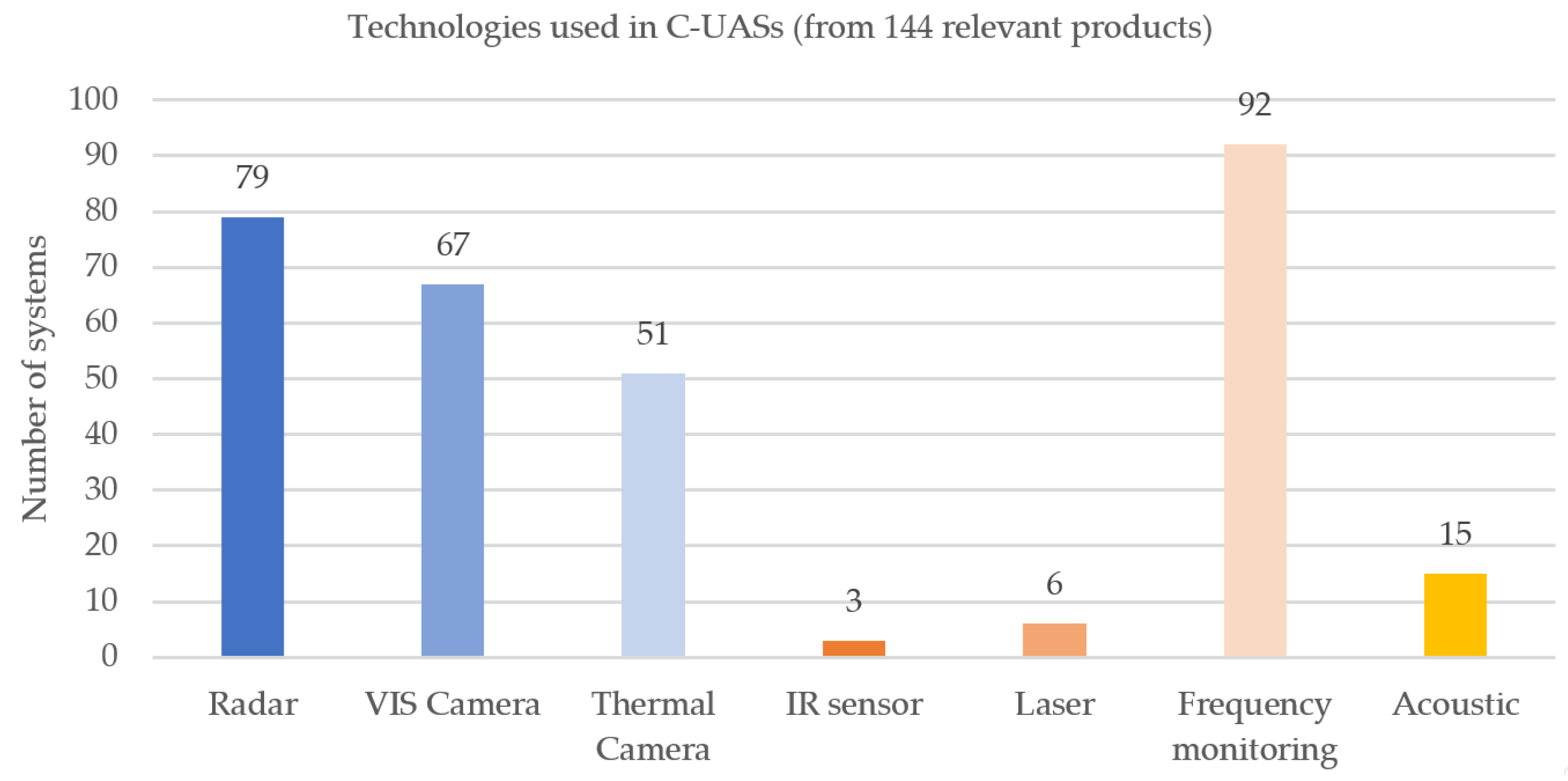
3.3. Analysis of Current Technologies

The choice of technology when selecting C-UASs is particularly important. Each of the methods of detecting and identifying drones has its limitations resulting from specific physical phenomena used in the operation of the given devices.
As part of the technological reconnaissance carried out, it should be noted that the commercial market is dominated by seven main technologies that are used in C-UASs, as shown in Figure 4. These are microwave radars [8], visible light cameras [9], thermal imaging cameras [10], infrared sensors (understood not as infrared cameras or long-range infrared sensors, the behaviour of which resembles a radar), lasers (understood as range-finding lidars) [11], frequency-monitoring systems [12], and acoustic sensors [13].
Due to the significant differences in the physical basis of the operation of the individual types of detection devices, it is worth highlighting the main shortcomings of the systems:
  • Not all detection methods enable 24/7 operation, especially at night.
  • The specificity of the operation, particularly IR (infrared sensors) and VIS (daylight) cameras, do not allow detection in satisfactory imaging zones with appropriate resolution. These technologies are mainly used to implement other functions: tracking and identification.
  • As an active detection method, the range of microwave radiation requires a thorough analysis of the possibility of using radar devices in terms of the approval for use (power, frequency) in a given scenario. Moreover, according to the properties of such radiation, a clear defining characteristic of a given device with respect to atmospheric conditions (rain, fog) is to be expected.

3.3.1. The Use of API

This subsection focuses on the possibilities of integrating the tested C-UAS solutions with external analysis and control systems. The most popular method of integration is the so-called application programming interface (API), a set of rules that closely describes how programmes or subroutines communicate with each other.
A good API makes it easier to build software, reducing it to the programmer combining blocks of elements in a set convention. It is defined at the source code level for software components, e.g., applications, libraries, and operating systems. The purpose of the application programming interface is to provide the appropriate specifications for subroutines, data structures, object classes, and the required communication protocols. One of the most popular types of API are web APIs, in which functions are made available as a resource on the web. Current web API systems allow one to easily integrate information from the web with applications, extending their functions or enabling interoperability.
However, in the case of the integration of C-UASs, which are an autonomous element that develop a decision on, e.g., detection or identification, it is not necessary to transmit raw data from the cameras. Therefore, in this case, it is much more efficient to use the SAPIENT (sensing for asset protection with integrated electronic networked technology) standard, which allows one to send the developed decisions from the autonomous elements of the system. An HTTP-based REST API would overburden bandwidth, while SAPIENT sends binary data to a TCP socket (server socket), which is more efficient. If one needs to take a screenshot from a camera, for example, it is possible to send the URL of the photo to the server, i.e., it is not sent directly. Taking into account the above information, SAPIENT is a much more tailored solution for the integration of C-UASs than REST API.

3.3.2. Other Parameters of C-UASs

Producers of the analysed C-UAS do not share information about integration methods with external systems, only paying attention to whether their C-UAS has such functionality (Figure 5). Only two manufacturers specify the possibility of integration with radar, camera, and mitigation systems. However, only one describes the API interface used, which can be accessed via JSON and gRPC. Nevertheless, it can be safely assumed that most of the systems that allow integration with external systems use the API interface due to its current universality.

3.4. Fusion of Technologies

This subsection presents the most commonly used combinations of technologies found in C-UASs. As is widely known, utilising different spectra of information enables the enhancement of the effectiveness of the final outcome of the decision-making system. Therefore, numerous manufacturers independently employ multiple technologies to complement reconnaissance information and mutually verify it with another technology. Artificial intelligence is often utilised during fusion, effectively extracting information from individual sources.

3.4.1. Combinations of Technologies Used in C-UASs

As mentioned above, the detection technologies that can be used are a finite set characterised by various parameters and offer different functionalities. This results directly from the range of the electromagnetic spectrum used or ranges of acoustic waves. According to the theory of external protection systems, the most effective system, defining an alarm signal with high probability, is a multi-spectral system. The analysis of the characteristics of the detected object, in various spectral ranges, with well-matched integration principles supported by numerical analysis, always gives the best result. With this in mind, on the basis of the market analysis, the finite set of available combinations of detection technologies offered on the market as a system were extracted, as shown in Figure 6.
Technologies used in anti-drone systems can be divided into active and passive, i.e., those that send a signal into space to detect an echo reflected from the object and those that detect the signal coming from the object without the need to “illuminate” it first. Active technologies include radars and lidars, which account for 28.6% of the available technologies. In contrast, 71.4% are passive technologies.
From a practical point of view, it is known that manufacturers are able to adjust the range of emitted electromagnetic radiation according to the legal requirements. The key, in this case, is to ensure that the standardisation of requirements in the proposed measurement methodology is compatible with practical possibilities vs. real test results. It should, therefore, be clearly declared what frequencies and radiation power are allowed in a given country and the scenario for active detection.

3.4.2. The Use of AI

C-UAS solutions very often enable decisions to be made about detection, identification, or tracking using only one technology for this purpose; however, additional technologies performing the same task can improve the efficiency of this process. The condition is that the results of individual classifications are similar, as a significantly weaker classifier may adversely affect the final results of the task. It is possible that C-UAS manufacturers use additional technologies to limit the set of results initially and then decide by using another technology or by applying the weights of the results obtained from individual technologies. Unfortunately, the manufacturers do not describe the details of this process. Figure 7 shows the likely possible correlations between the pairs of technologies used by C-UAS producers.
The compared C-UAS solutions often contain information about the use of artificial intelligence and machine learning when supporting the process of object detection and drone tracking. AI is also used during image recognition so that a specific type, brand, or model of drone can be identified. The use of AI should also be distinguished in the process of the holistic determination of a detected object as a threat.
All these elements, due to the appropriate correlation and perceived as a whole, may allow the system to qualify the object to the adopted threat level. When correlating information from different sources, one of the key elements is the correct selection of information. For this purpose, artificial intelligence algorithms are very useful.
Unfortunately, in many cases, there is only a stripped-down description of the machine learning methods used, among which are also traditional statistical methods. Furthermore, the use of artificial intelligence is now a “fashionable” trend that is often used only as a sales method, so in some cases, it is possible that manufacturers will exploit this phrase.
Figure 8 shows a pie chart of manufacturers of C-UAS solutions that use artificial intelligence methods when making decisions. Unfortunately, in the vast majority of cases, there is no information about the classification methods used during the detection and identification of drones.

3.5. Legal Aspects in C-UAS

From a legal point of view, there are two main drone detection techniques that are interesting, characterised by the use of active (energy-emitting) technologies. These are radars emitting radio waves and lidar devices emitting laser light. Each of these techniques can be analysed in the context of current legal regulations, taking into account their physical characteristics. The emission of radio waves can be analysed in the context of regulations concerning telecommunications and radio equipment (including standards), whereas drone detection techniques based on emitting laser light can be analysed in the context of laws and standards concerning the emission of laser light.
It is worth noting that the law may vary in different European Union countries [14], apart from EU-wide regulations, and this aspect is not described here.
Regarding devices emitting radio waves, the regulations of Directive 2014/53/EU of the European Parliament and of the Council are relevant. According to Article 16 of this Directive, it is assumed that radio equipment which complies with harmonised standards or parts thereof, the references to which have been published in the Official Journal of the European Union, complies with the essential requirements set out in Article 3 of this Directive. On this basis, the Commission Implementing Decision (EU) 2020/1562 of 26 October 2020 (amending the Implementing Decision (EU) 2020/167) concerning harmonised standards for radio equipment provides references to harmonised standards for radio equipment developed to support Directive 2014/53/EU.
These requirements include the safety of radio equipment use, proper installation and connection, the protection of persons and animals against the risk of bodily harm or other damage that may result from direct or indirect contact with radio equipment, and protection against threats that may result from external influences on or from radio equipment (electromagnetic compatibility). Radio equipment is subject to mandatory conformity assessment with all the listed requirements.
Additionally, it should be noted that the use of devices emitting radio waves without permission is allowed only for specified frequencies and powers. Devices emitting frequencies other than those permitted or of higher power require authorisation and payment for using the radio spectrum.
In the case of lasers (lidar), according to the Commission Implementing Decision (EU) 2021/2273 of 20 December 2021, amending the Implementing Decision (EU) 2019/1956 with regard to harmonised standards for laser products, the safety standard EN 60825-1:2014 for laser products is regulated. The EN 60825-1:2014 standard introduces a classification system for laser-related hazards, specifies requirements for users and manufacturers, provides an appropriate warning system through markings, labels, and instructions, and minimises the risk of injury by limiting available radiation.

4. Our Experiences

In this section, the authors succinctly discuss their extensive experience with the technologies utilised in C-UASs. This section begins by listing the limitations associated with individual technologies, which arise from both the theoretical considerations of physical phenomena and the authors’ experimental experiences. The second part of this section is dedicated to the methodology of the conducted C-UAS tests. A detailed presentation of the C-UAS testing methodology significantly exceeds the quantitative limitations of this article. Therefore, the authors have presented the most essential information regarding the generated test scenarios; operational, functional, and performance requirements; and metrics, in their opinion. The mentioned elements of the methodology constitute a logical whole derived from the other considerations. This allows for simulating a real-life situation of using C-UASs in one of the proposed scenarios and identifying the corresponding functional and performance requirements, as well as determining appropriate metrics that will allow one to become independent of environmental conditions. The entirety enables the repeatable conducting of experiments under similar testing conditions and facilitates the comparison of different C-UASs.

4.1. Limitations of Technologies

As mentioned above, various technologies are used to detect UASs. Each of them has certain limitations that may lower the probability of UAS detection.
The limitations of radars resulting from physical phenomena related to their operation are as follows:
  • Active detection method—possible interference with the radar signal.
  • Active detection method—it is possible to detect the presence of a radar.
  • The response characteristics of radars, depending on the weather conditions, strongly depend on the frequency of use. In general, the higher the frequency, the greater the attenuation of water molecules (fog, rain).
  • The lower the frequency of the radars, the more difficult it is to detect small objects.
  • The continuous wave (CW) radar movement of the object cross-wise to the radar is difficult to detect under certain conditions, especially for low-power radars [15].
  • The disturbance may come from the multiplication of the real object in the case of echo reflection from the Earth’s surface or the atmosphere.
  • In many cases, the interference signal reaching the radar receiver from longer distances exceeds the echo level of the useful target in its power. The ultimate performance characteristics of the detection system are solely contingent upon the quality of the firmware employed for analysis.
  • Due to the shorter distance travelled by the interference signal (the useful signal must travel two times—from the transmitter to the interference source and back again—compared to the interference emitted by the target), the power emitted by the interference transmitter may be much smaller and, therefore, unable to effectively interfere with the working radar.
  • The use of SPFA systems that can control the detection level in the presence of environmental disturbances can significantly reduce the detection range.
The limitations of visible light cameras resulting from physical phenomena related to their operation are as follows:
  • These systems are designed for imaging under stable lighting conditions within the observation area, where radiation in the visible light spectrum is confined to a precisely defined level, and are not suitable for use at night;
  • The limitations are strictly related to the choice of the lens and its parameters;
  • The resolution of image detection relies on both the resolution of the sensor matrix and the focal length of the lens, which together determine the range of the observation field;
  • The ability to indicate the distance of an object is limited only to predictions from the calculation of the potential size of the object;
  • It is difficult (software) to indicate the coordinates of the object;
  • The quality of object tracking depends on the adopted image analysis method;
  • The dynamics of image lighting (clouds, sun, etc.) significantly affect the detection of the object in the image;
  • Light reflections from dirt on the lens disqualify the solution from use.
The limitations of thermal imaging cameras resulting from physical phenomena related to their operation are as follows:
  • Poor image adjustment/sharpness; better quality available only in motor zoom systems.
  • Thermal imaging cameras are passive, which means that they detect all infrared radiation coming from a target. This means that what the viewer sees through the camera is not limited to the heat emitted by the object but can also be the result of energy reflected from the surface they are looking at, coming from other sources.
  • The identification ability of thermal imaging cameras is limited by weather phenomena. Fog, snow, and rain suppress infrared waves, which reduce the camera’s range of effective detection and imaging.
  • Cloudy conditions strongly affect the interpretation of the image, especially of small objects over long distances.
  • The key parameter of a thermal imaging camera is the MRTD, which means that cooled matrices are better for the imaging of objects.
  • The limitation in use is closely related to the choice of the lens and its parameters.
  • The resolution of image detection depends on the matching of the matrix resolution and the focal length of the lens (field of view range).
  • The ability to indicate the distance of an object is limited only to predictions from the calculation of the potential size of the object.
  • It is difficult (in terms of software) to indicate the coordinates of the object.
  • The quality of object tracking depends on the adopted image analysis method.
  • Firmware is most often closed under one manufacturer and the possibility of integration is limited to the functions provided by the SDK.
  • The detectability of objects strictly depends on the emissivity of the material from which it was made. The ambient temperature is required to compensate for the radiation reflected from the object. If the emissivity of the object is low, then the correct setting of the ambient temperature is of key importance.
  • There may be a problem with detecting and/or interpreting detected shiny objects.
The limitations of IR sensors resulting from physical phenomena related to their operation are as follows:
  • The limitations are similar to the limitations of thermal imaging cameras when the IR sensor is a rotating thermal imager;
  • The rotation frequency of the thermal imaging camera is limited to a single Hz and the image analysis depends on comparing the sequence of image changes every second;
  • The ability to indicate the distance of an object limited only to predictions from the calculation of the potential size of the object;
  • The field of view (lens) and the size of the matrix as well as mounting on a rotating platform limit the resolution of the measurement over a long distance.
The limitations of the laser lidars resulting from physical phenomena related to their operation are as follows:
  • The distance measurement may be disturbed by a drone other than the one intended;
  • Drones cannot be tracked;
  • The distance measurement may be distorted by unfavourable weather conditions such as a high extinction coefficient and insolation;
  • The reflected power from the subject may be too low to filter out from the noise;
  • The power radiated towards the object must be sufficiently high, but not too high, so as not to cause damage;
  • The optical wavelength of the laser must be eye-safe (so as not to dazzle pilots/people, etc.);
  • It is an active method, which means it is possible to detect the irradiation/lighting of the object;
  • Scattering of the 1550 nm wavelength on water molecules (rainfall, fog, etc.).
The limitations of frequency-monitoring devices resulting from physical phenomena related to their operation are as follows:
  • This type of system is prone to deliberate interference;
  • The electronic-background-rich environment significantly reduces the detection efficiency;
  • Most solutions only define possible threats in terms of direction without specifying the correct object distance;
  • The detection, tracking, and identification of objects is limited by the presence of natural and artificial terrain obstacles creating covered zones;
  • The detection range drops significantly due to interference from other devices (in an urbanised area);
  • Most frequency-monitoring systems only detect Wi-Fi frequencies (2.4 GHz and 5 GHz) and, therefore, have a narrow detection range.
The limitations of acoustic sensors resulting from physical phenomena related to their operation are as follows:
  • This type of sensor has very large range limitations;
  • Detection can be easily disturbed by noise/wind (both urbanised noisy areas and open spaces with blowing winds are unfavourable for this type of sensor);
  • The elimination of non-linear acoustic disturbances, which hinders the interpretation of the tested signals, is problematic.

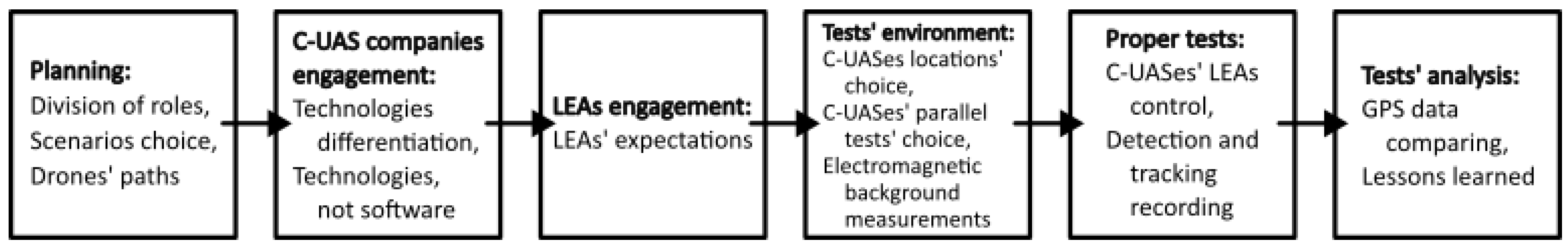
4.2. Evaluation Method

The following scheme was adopted, from the end-users’ needs in terms of protection against threats arising from the unauthorised and illegal use of drones to the technical requirements imposed on them. Ten standard scenarios were considered based on the analysis of events that occurred and potential highly dangerous incidents.
The ten usage scenarios developed within the COURAGEOUS project (divided into three categories) are:
  • Sensitive Sites/Critical National Infrastructure:
    1.
    Prison;
    2.
    Airport;
    3.
    Nuclear plant;
    4.
    Government building.
  • Public Spaces Protection/Events:
    5.
    Stadium;
    6.
    Outdoor concert;
    7.
    Outdoor political rally;
    8.
    International summit.
  • Border Protection:
    9.
    Land border;
    10.
    Maritime border.
In the first step, operational needs were defined. They describe what authorities need to eliminate or mitigate the threats posed by the illegal use of a UAS, particularly in the hands of criminals, including terrorists, to protect various places, facilities, events, and individuals (in general: assets).
In the next step, functional requirements for the C-UAS were determined based on operational needs. They describe what functions C-UASs shall, should, or may fulfil to meet operational needs.
The next step was to transition from functional requirements to C-UAS performance requirements. Performance requirements focus on the technical parameters that must be met by the C-UAS to fulfil their tasks, in relation to individual scenarios specified in operational needs and functional requirements.
The results of the above analysis are metrics defining the technical parameters that must be examined during tests to compare which of the proposed technical solutions will be most appropriate for any given assets and adopted threat scenario.
Many factors will affect the proper functioning and thus, the quality of C-UAS operation. Weather conditions are variable and difficult to predict. However, they will differ depending on the location of the assets to be protected. It would be most beneficial to check the operation of the proposed solutions in all weather conditions that may occur for a given location. Since the laboratory testing of C-UASs is not feasible due to the size of the area required for research, it is necessary, for the purpose of comparing different systems, to conduct precise measurements of weather conditions during testing. This requirement pertains to the proposed metrics related to weather measurements.
Regardless of the geographical location in which the C-UAS will be used, the degree of urbanisation in the area is very important. Assets located in the centre of a large city will expose a C-UAS to more radio frequency interference, they may be shielded by buildings, or they may be near objects emitting various types of energy (thermal, radio, etc.). In turn, assets to be protected located outside city limits may be shielded by forests, making it difficult to detect a UAS from a distance, and the lack of terrain obstacles may allow the UAS to reach high speeds, thereby limiting the number of possible asset protection scenarios despite its detection.
All of the above aspects were taken into account when developing metrics describing which parameters of C-UASs should be considered depending on the scenario and location of the assets.
Sample quantities subject to measurement during tests are provided below:
  • Specification of environmental conditions;
  • Specification of the test object, i.e., UAS [16];
  • Specification of the test site;
  • Testable parameters for detection, tracking, and identification.
As an addition to the metrics, a table has been developed on how to conduct tests to make them repeatable.
Due to the previously mentioned impact of weather and other environmental conditions on the tests, the parameters that should be measured in order to compare test results are presented in Table 2.
As part of the development of the COURAGEOUS project, individual C-UASs will be evaluated based on a multiple-criteria decision analysis (MCDA). Due to the diverse requirements of end-users of C-UAS technology and the variety of test scenarios, it is not possible to arbitrarily establish a fixed set of functional and performance requirements for C-UASs or assign them permanent weights. Therefore, the specific requirements and their weights will be determined individually prior to the multiple-criteria comparisons of C-UASs. Nevertheless, it is possible to formulate a general model (1) that allows for a quantified, single-value assessment of individual systems:
S i = j = 1 n w j · a i j
where:
  • Si is the aggregate evaluation of the ith C-UAS.
  • wj is the weight of the jth functional or performance requirement.
  • aij is the evaluation of the ith C-UAS according to the jth functional or performance requirement.
  • n is the number of functional or performance requirements considered in the evaluation of the C-UAS.

5. A Simplified Algorithm for the Use of C-UAS Effectiveness Evaluation Methods

In summary, the proposed methods for assessing the effectiveness of modern counter unmanned aircraft systems, developed within the COURAGEOUS project, are presented in the form of a simplified algorithm in Figure 9.

6. Conclusions

The article is the result of work carried out within the COURAGEOUS project. This project allowed for an innovative approach to such a significant issue as protecting important locations from illegal drone use. The focus of the project was not on determining which drone detection, tracking, and identification technology is superior but rather on evaluating which of the existing and future solutions is better suited to a given location or threat scenario.
Through the development of threat recognition within the COURAGEOUS project, 10 scenarios of unlawful drone use were identified. Technological advancements have made these devices widely available and affordable, offering significant potential for various applications, including criminal and terrorist activities.
By assessing the market of counter unmanned aircraft systems and understanding the technologies and physical phenomena utilised within them, as well as their associated limitations, the operational needs were defined for each scenario. These needs evolved into functional and performance requirements and, ultimately, metrics enabling the evaluation of the suitability of a specific solution for a particular scenario and the object or event described therein.
The approach presented in this article for assessing the suitability of a specific C-UAS is unique, allowing for a highly versatile approach to the issue of protection against illegal drone use. According to the authors, the proposed methodology for conducting C-UAS tests constitutes a significant contribution to the field. Among other considerations, due to the unprecedented scale of the C-UASs analysed in the literature (as many as 260) and the logical implication of the presented studies, it is possible to say that the developed methodology is universal and can be successfully adapted to new, not-yet-existing solutions and scenarios. A thorough, individually assessed solution evaluation tailored to specific needs plays a crucial role in minimising the risks posed by this new UAS technology.
In the next phase, it may be important to examine a larger and different group of C-UASs from those currently studied, and to expand the list of end-users participating in the development of the C-UAS testing methodology.
The anticipated future tests should be extended to include the following elements:
  • Detection of drones moving within the test area at various angles relative to the ground;
  • Determination of the minimum distances between two drones allowing for their distinguishability;
  • Conducting dedicated tests for specific technologies and their various variants;
  • Including flights of drones moving at speeds exceeding 120 km/h in the tests;
  • Examining the impact of external electromagnetic interference on technologies used by C-UASs;
  • Adapting test scenarios to potentially emerging new UAS and C-UAS technologies;
  • Developing and integrating tests into an automatic/semi-automatic C-UAS testing system.

Author Contributions

Conceptualization, M.Ż., P.P. and G.D.C.; methodology, K.C. and K.D.B.; software, K.D.B. and K.C.; validation, P.P. and G.D.C.; formal analysis, K.D.B., K.C. and K.A.K.; investigation, K.D.B., K.C. and K.A.K.; resources, K.D.B. and K.C.; data curation, K.A.K.; writing—original draft preparation, K.D.B., K.C. and K.A.K.; writing—review and editing, M.Ż., P.P. and G.D.C.; visualization, K.D.B.; supervision, M.Ż. and G.D.C.; project administration, G.D.C.; funding acquisition, G.D.C. All authors have read and agreed to the published version of the manuscript.

Funding

This research was funded by the European Union’s Internal Security Fund Police, grant number 101034655 (project: Building towards a better understanding of the capabilities of counter-UAS—COURAGEOUS).

Data Availability Statement

The original contributions presented in the study are included in the article, further inquiries can be directed to the corresponding author/s.

Acknowledgments

We would like to thank Chris Church (INTERPOL), who provided a collection of UAS incidents; Razvan Roman (SPP), Sima Silviu (SPP), and Laurentiu Chioseaua (SPP) for providing the operational requirements for C-UASs; and Ivan Maza (USE) for the inspiration to implement the test methodology and the implementation of UAS test reports.

Conflicts of Interest

The authors declare no conflicts of interest.

References

  1. Vargas-Ramírez, N.; Paneque-Gálvez, J. The Global Emergence of Community Drones (2012–2017). Drones 2019, 3, 76. [Google Scholar] [CrossRef]
  2. Franke, U. Drone Proliferation: A Cause for Concern? International Relations and Security Network (ISN), ETH Zürich: Zürich, Switzerland, 2014. [Google Scholar]
  3. Aksu, M.O.; Alwardt, C.; Berndsen, C.I.S.; Bollö, J.; Cochran, C.D.; Corum, J.; Dieckert, U.; Eckel, H.-A.; Grest, L.C.H.; Haider, L.C.A.; et al. A Comprehensive Approach to Countering Unmanned Aircraft Systems. Willis, C.M., Haider, L.C.A., Teletin, L.C.D.C., Wagner, L.C.D., Eds.; The Joint Air Power Competence Centre: Kalkar, Germany, 2021. [Google Scholar]
  4. Doroftei, D.; De Cubber, G. Qualitative and Quantitative Validation of Drone Detection Systems. In Proceedings of the International Symposium on Measurement and Control in Robotics ISMCR2018, Mons, Belgium, 26–28 September 2018. [Google Scholar]
  5. Buric, M.; De Cubber, G. Counter Remotely Piloted Aircraft Systems. MTA Rev. 2017, 27, 9–18. [Google Scholar]
  6. Lee, C.H.; Thiessen, C.; Van Bossuyt, D.L.; Hale, B. A Systems Analysis of Energy Usage and Effectiveness of a Counter-Unmanned Aerial System Using a Cyber-Attack Approach. Drones 2022, 6, 198. [Google Scholar] [CrossRef]
  7. Skolnik, M.I. Radar Handbook; McGraw-Hill: New York, NY, USA, 1990; ISBN 007057913X. [Google Scholar]
  8. Zyczkowski, M.; Szustakowski, M.; Ciurapinski, W.; Karol, M.; Markowski, P. Integrated Radar-Camera Security System: Range Test. In Proceedings of the SPIE Defense, Security, and Sensing, Baltimore, MD, USA, 23–27 April 2012; Volume 8361, pp. 493–502. [Google Scholar] [CrossRef]
  9. Rozantsev, A. Vision-Based Detection of Aircrafts and UAVs. Master’s Thesis, EPFL, Lausanne, Switzerland, 2017. [Google Scholar]
  10. Andraši, P.; Radišić, T.; Muštra, M.; Ivošević, J. Night-Time Detection of UAVs Using Thermal Infrared Camera. Transp. Res. Procedia 2017, 28, 183–190. [Google Scholar] [CrossRef]
  11. De Cubber, G.; Shalom, R.; Coluccia, A.; Borcan, O.; Chamrad, R.; Radulesku, T.; Izquierdo, E.; Gagov, Z. The SafeShore System for the Detection of Threat Agents in a Maritime Border Environment. In Proceedings of the IARP Workshop on Risky Interventions and Environmental Surveillance, Les Bons Villers, Belgium, 18–19 May 2017; pp. 1–4. [Google Scholar]
  12. Wang, J.; Liu, Y.; Song, H. Counter-Unmanned Aircraft System(s) (C-UAS) State of the Art, Challenges and Future Trends. IEEE Aerosp. Electron. Syst. Mag. 2021, 36, 4–29. [Google Scholar] [CrossRef]
  13. Mezei, J.; Molnar, A. Drone Sound Detection by Correlation. In Proceedings of the SACI 2016-11th IEEE International Symposium on Applied Computational Intelligence and Informatics, Timisoara, Romania, 12–14 May 2016; Institute of Electrical and Electronics Engineers Inc.: Piscataway, NJ, USA, 2016; pp. 509–518. [Google Scholar]
  14. Stöcker, C.; Bennett, R.; Nex, F.; Gerke, M.; Zevenbergen, J. Review of the Current State of UAV Regulations. Remote Sens. 2017, 9, 459. [Google Scholar] [CrossRef]
  15. Li, C.J.; Ling, H. An Investigation on the Radar Signatures of Small Consumer Drones. IEEE Antennas Wirel. Propag. Lett. 2017, 16, 649–652. [Google Scholar] [CrossRef]
  16. Farlik, J.; Kratky, M.; Casar, J.; Stary, V. Multispectral Detection of Commercial Unmanned Aerial Vehicles. Sensors 2019, 19, 1517. [Google Scholar] [CrossRef] [PubMed]
Figure 1. Research framework of the COURAGEOUS project.
Remotesensing 16 03714 g001
Figure 2. Structural description of the COURAGEOUS project.
Remotesensing 16 03714 g002
Figure 3. Relevant (according to the COURAGEOUS project) C-UAS products.
Remotesensing 16 03714 g003
Figure 4. Technologies used for detecting, tracking, and identifying (DTI) in C-UAS solutions.
Remotesensing 16 03714 g004
Figure 5. Integration of the C-UAS solution with external control and analysis systems.
Remotesensing 16 03714 g005
Figure 6. Combinations of technologies used in C-UAS solutions. The data label contains the percentage share of the given combination of technologies in relation to the C-UASs present in the base and the number of them.
Remotesensing 16 03714 g006
Figure 7. C-UAS technology correlation.
Remotesensing 16 03714 g007
Figure 8. The use of AI in the detection and identification of drones.
Remotesensing 16 03714 g008
Figure 9. A simplified algorithm for assessing the effectiveness of modern C-UASs.
Remotesensing 16 03714 g009
Table 1. Capabilities and limitations of technologies used in C-UASs.
TechnologyCapabilities (Defining or Measuring)Limitations
DetectionSpeedDirectionAltitudeSizeDistanceTrackingIdentificationWindRainFogInsolationElectromagnetic Disturbance
Radar1✓/- 2✓/- 3--✓/-✓/--✓/-
VIS Cam.✓/- 4---✓/--
Thermal Cam.✓/- 4---✓/- 5✓/- 6--
IR✓/- 4---✓/- 5✓/- 6--
Laser-✓/- 7-✓/- 8----✓/- 5✓/- 6-
Frequency✓/- 9✓/- 9✓/- 9-✓/- 9----
Acoustic-✓/- 10---✓/- 1011---
The symbol ✓ indicates that a specific capability or limitation exists in the given technology. The symbol—signifies that a specific capability or limitation does not exist in the given technology. The symbol ✓/- indicates that a specific capability or limitation may or may not exist. For example, a particular capability might be present in the given technology with the use of additional software, but without this software, it will not be present. Further explanations are provided below (or in the previous text) using points (1–11): 1 Depending on the radar technology employed. 2 Depending on the radar technology employed, e.g., FMCW 3D Robin, such a capability is available. 3 Radar cross-section (RCS) provides indirect information about the size. Further explanation is in the text (lines 217−221). 4 Explanation is in the above text (lines 250–263, 285–287). 5 Depending on the intensity of the rain. 6 Depending on the intensity of the fog; in dense fog, the range of the technology will significantly decrease. 7 If the drone is continuously illuminated by laser radiation, it is possible to assess the speed of the drone. 8 By knowing the distance and angle, it is possible to determine the height of the drone. 9 Depending on the technology and software used, if only frequency monitoring is employed—no, if the signal is decoded—yes. With the use of multiple antennas and triangulation—yes. 10 With a sufficiently large number of microphones, their appropriate directionality, and proper placement, it is possible to determine the direction of the drone, and it is possible to track it. 11 Explanation is in the above text (lines 301–305).
Table 2. Environmental conditions to be measured during C-UAS tests.
Type of
Conditions
Parameter
Meteorological conditionsMedium surface wind
Visibility
Height of the cloud base
Air temperature and dew point temperature
Pressure value (QNH, QFE)
Average wind measured
Air temperature measured
Water surface temperature, if the scenario assumes its occurrence
Illuminance
Electromagnetic
conditions
Average intensity of the electromagnetic field in the considered frequency range
Peak intensity of the electromagnetic field in the considered frequency range
Acoustic
conditions
Average sound level
Peak sound level and frequency at which it occurs
Disclaimer/Publisher’s Note: The statements, opinions and data contained in all publications are solely those of the individual author(s) and contributor(s) and not of MDPI and/or the editor(s). MDPI and/or the editor(s) disclaim responsibility for any injury to people or property resulting from any ideas, methods, instructions or products referred to in the content.

