Next Article in Journal
CLOUDSPAM: Contrastive Learning On Unlabeled Data for Segmentation and Pre-Training Using Aggregated Point Clouds and MoCo
Previous Article in Journal
Comparison of Different Quantitative Precipitation Estimation Methods Based on a Severe Rainfall Event in Tuscany, Italy, November 2023
Previous Article in Special Issue
Spherical Magnetic Vector Forwarding of Isoparametric DGGS Cells with Natural Superconvergent Points
 
 
remotesensing-logo
Article Menu

Article Menu

Article

The Scintillation Counters of the High-Energy Particle Detector of the China Seismo-Electromagnetic (CSES-02) Satellite

by
Simona Bartocci
1,
Roberto Battiston
2,3,
Stefania Beolè
4,5,
Franco Benotto
5,
Piero Cipollone
6,
Silvia Coli
5,
Andrea Contin
7,8,
Marco Cristoforetti
3,9,
Cinzia De Donato
6,
Cristian De Santis
6,
Andrea Di Luca
3,9,
Floarea Dumitrache
5,
Francesco Maria Follega
2,3,
Simone Garrafa Botta
5,
Giuseppe Gebbia
2,3,
Roberto Iuppa
2,3,
Alessandro Lega
2,3,
Mauro Lolli
8,
Giuseppe Masciantonio
6,
Matteo Mergè
10,
Marco Mese
11,12,
Riccardo Nicolaidis
2,3,
Francesco Nozzoli
3,
Alberto Oliva
8,
Giuseppe Osteria
12,
Francesco Palma
6,
Federico Palmonari
7,8,
Beatrice Panico
11,12,
Stefania Perciballi
4,5,
Francesco Perfetto
12,
Piergiorgio Picozza
6,13,
Michele Pozzato
8,
Ester Ricci
2,3,
Marco Ricci
14,
Sergio Bruno Ricciarini
15,
Zouleikha Sahnoun
7,8,*,
Umberto Savino
4,5,
Valentina Scotti
11,12,
Enrico Serra
3,
Alessandro Sotgiu
6,
Roberta Sparvoli
6,13,
Pietro Ubertini
16,
Veronica Vilona
3,
Simona Zoffoli
10 and
Paolo Zuccon
2,3
add Show full author list remove Hide full author list
1
Istituto Nazionale di Fisica Nucleare (INFN)—Amministrazione Centrale, Via E. Fermi 54, 00044 Frascati, Italy
2
Dipartimento di Fisica, Università di Trento, Via Sommarive 14, 38123 Trento, Italy
3
Istituto Nazionale di Fisica Nucleare (INFN)—Trento Institute for Fundamental Physics and Applications (TIFPA), Via Sommarive 14, 38123 Trento, Italy
4
Dipartimento di Fisica, Università di Torino, Via P. Giuria 1, 10125 Turin, Italy
5
Istituto Nazionale di Fisica Nucleare (INFN)—Sezione di Torino, Via P. Giuria 1, 10125 Turin, Italy
6
Istituto Nazionale di Fisica Nucleare (INFN)—Sezione di Roma Tor Vergata, Via della Ricerca Scientifica 1, 00133 Rome, Italy
7
Dipartimento di Fisica, Università di Bologna, Viale Berti Pichat 6/2, 40127 Bologna, Italy
8
Istituto Nazionale di Fisica Nucleare (INFN)—Sezione di Bologna, Viale Berti Pichat 6/2, 40127 Bologna, Italy
9
Fondazione Bruno Kessler (FBK), Via Sommarive 18, 38123 Trento, Italy
10
Italian Space Agency (ASI), Via del Politecnico, 00133 Rome, Italy
11
Dipartimento di Fisica, Università degli Studi di Napoli Federico II, Via Cintia, 80126 Naples, Italy
12
Istituto Nazionale di Fisica Nucleare (INFN)—Sezione di Napoli, Via Cintia, 80126 Naples, Italy
13
Dipartimento di Fisica, Università di Roma Tor Vergata, Via della Ricerca Scientifica 1, 00133 Rome, Italy
14
Istituto Nazionale di Fisica Nucleare (INFN)—Laboratori Nazionali di Frascati (LNF), Via E. Fermi 54, 00044 Frascati, Italy
15
Consiglio Nazionale delle Ricerche (CNR)—Istituto di Fisica Applicata “Nello Carrara” (IFAC), Via Madonna del Piano 10, 50019 Florence, Italy
16
Istituto Nazionale di Astrofisica (INAF)—Istituto di Astrofisica e Planetologia Spaziali (IAPS), Via Fosso del Cavaliere 100, 00133 Rome, Italy
*
Author to whom correspondence should be addressed.
Remote Sens. 2024, 16(21), 3982; https://doi.org/10.3390/rs16213982
Submission received: 9 August 2024 / Revised: 10 October 2024 / Accepted: 21 October 2024 / Published: 26 October 2024

Abstract

:
The High-Energy Particle Detector (HEPD-02) is one of the scientific payloads of the China Seismo-Electromagnetic Satellite (CSES-02). The HEPD-02’s main purpose is to characterize the particle environment in the Earth’s vicinity, identifying sudden changes in the fluxes and correlating them with solar and terrestrial phenomena. Additionally, HEPD-02 also has capabilities in detecting Gamma-Ray Bursts. At the core of HEPD-02, a tower of scintillation counters made of plastic and LYSO crystals is able to recognize electrons in the range between 3 and 100 MeV, protons and nuclei between 30 and 200 MeV/n. Plastic scintillators covering the calorimeter on five sides allow to reject particles entering from the top and not completely absorbed within its volume. In this work, the design of the HEPD-02 is reviewed in comparison to its predecessor, HEPD-01, highlighting the innovations of the new design. The design of each scintillation counter type has been fully validated through a campaign of prototype realization, testing, and characterization. The production of the scintillation counters, including the PMT selection process, is also discussed. Finally, the performance of the counters is compared with simulations, showing an agreement of within 20% with the expected performance, thereby meeting expectations.
PACS:
29.40.Mc; 07.20.Fw; 94.80.+g; 85.60.Ha

Graphical Abstract

1. Introduction

The China Seismo-Electromagnetic Satellite (CSES) is a space program a space program in collaboration between China and Italy, aimed at the study of the electromagnetic, plasma, and particle environment in low Earth orbit, with the main purpose of correlating perturbations observed in the magnetosphere with seismic activity [1,2]. The first satellite, CSES-01, was launched in February 2018 and is currently collecting data. A second satellite, CSES-02, will be launched at the end of 2024.
Both satellites are hosting, among several other instruments, a High-Energy Particle Detector (HEPD-01, HEPD-02), aimed at measuring the flux of electrons, protons, and nuclei in the few to a hundred MeV range. HEPD is dedicated to look for sudden increases in particle counts, i.e., particle bursts, due to particles precipitating from the Van Allen belts, and to study possible correlations with disturbances caused by solar or terrestrial phenomena. Moreover, HEPD-01 already demonstrated the capabilities of this kind of detector in characterizing the radiation environment around the Earth, such as the trapped component in the South Atlantic Anomaly [3]; in monitoring the solar activity through the detection of Solar Energetic Particles [4]; and also in the detection of Gamma-Ray Bursts (GRBs) [5].
The HEPD-02 detector introduces two main innovations ever used in a space-based experiment: Monolithic Active Pixel Sensors (MAPSs) for particle tracking [6], and the longest ever employed Cerium-doped Lutetium–Yttrium Oxyorthosilicate ( Lu 2 ( 1 x ) Y 2 x SiO 5 :Ce, or LYSO) of 15 cm. The manufacturing of the latter has been complex, but its use allows for both excellent energy measurements and presents capabilities in GRB detection [7,8].
The HEPD-02 scintillation counter system is designed to generate the trigger signal for the entire experiment, identify different types of particles, measure their energy, and detect particles entering or exiting the inner calorimetric region from the sides or bottom.
The HEPD-02 scintillation counter system introduces several improvements over the HEPD-01 design. First, the HEPD-02 LYSO scintillators are segmented into two layers, each containing three bars, compared to the single layer of nine cubes used in HEPD-01. These longer bars are read from both ends by two photomultiplier tubes (PMTs), enhancing light collection efficiency. The use of LYSO bars also improves the mechanical design by reducing the amount of passive material that particles must traverse. Second, the inclusion of a 2 mm triggering plane at the top of the HEPD-02 extends the instrument’s energy range to lower energies and enhances particle separation.
In Section 2, the HEPD-02 full detector is illustrated. In Section 3, the measurements performed to validate the design of all the counters are described. In Section 4, the additional characterization of LYSO crystals is shown, and in Section 5, the PMT characterization procedure and the sorting and coupling to scintillators are discussed. Finally, a Monte Carlo simulation able to reproduce the behavior of the HEPD-02 scintillation counters will be discussed in Section 6.

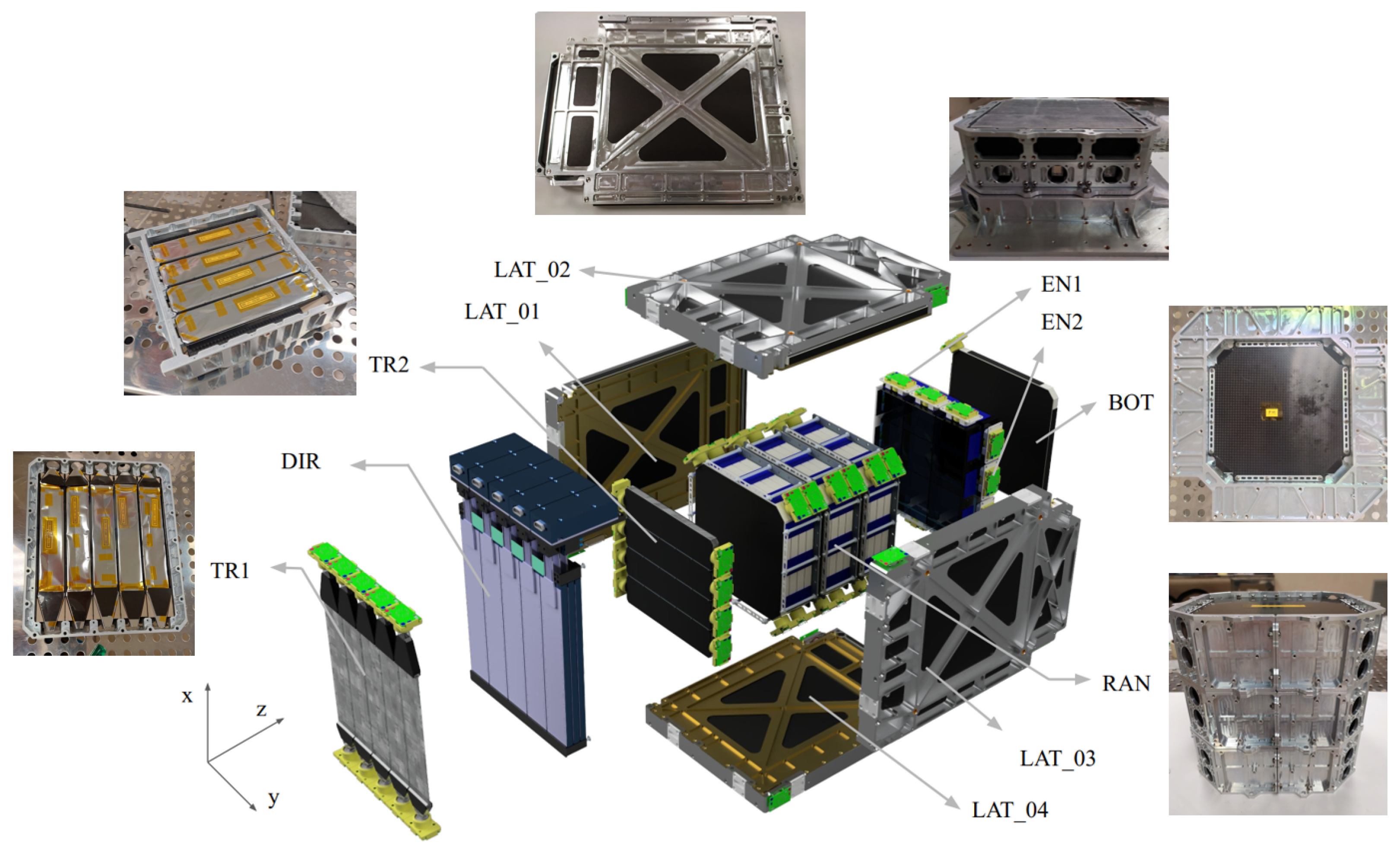
2. The High-Energy Particle Detector

The HEPD-02 design [9] is an improvement of the HEPD-01 detector [2]. The instrument is composed of a trigger system, a direction detector, a range detector, and an energy detector. The typical response of the full HEPD-02 detector is shown in Figure S1 of the Supplementary Materials, where the signal released by a 228 MeV proton traversing the detector is displayed. An exploded view of the system, with photos of the modules, before the final assembly is presented in Figure 1, wherein, from the left to the right side of the figure, the following are shown:
  • Trigger Detector (TR1): The plane is made up of five 2 mm thick, plastic scintillation counters of 32 × 154   mm 2 . Both ends of each scintillator are coupled to flat, 6 mm thick, light guides. The light guides, in a trapezoidal shape, have different lengths on the two sides—25 mm at one side and 46 mm at the other. Each guide ends in a 6 × 8   mm 2 window where it is coupled to the PMT active area. TR1 thickness is kept to a minimum to allow for the triggering of MeV particles that are of particular interest for the HEPD-02 physics.
  • Direction Detector (DIR): It has dimensions of 150 × 150   mm 2 and is made of five standalone tracking modules, each composed of three layers of MAPS [6].
  • Trigger Detector (TR2): The second trigger plane is composed of four 8 mm thick plastic scintillators, oriented perpendicularly to TR1 counters, with dimensions of 36 × 150   mm 2 .
  • Range Detector (RAN): The calorimeter is divided into two sections, whereby the upper one is made of a tower of twelve 10 mm thick plastic scintillators with dimensions of 150 × 150   mm 2 , named RAN1 to RAN12, enclosed into three separated mechanical units.
  • Energy Detector (EN): The bottom part of the calorimeter is composed of two orthogonal layers, EN1 and EN2, of three 25 mm thick LYSO crystal bars measuring 49 × 150   mm 2 .
  • Containment Detector (CD): Five 8 mm thick plastic scintillator panels enclose the detection volume and, in anti-coincidence with the trigger, reject particles not completely absorbed into the calorimeter. The bottom panel (BOT) has dimensions measuring 166 × 166   mm 2 , while the lateral ones (LAT) have an envelope size of 212 × 286   mm 2 .
The scintillation counter system of HEPD-02 (including TR1, TR2, RAN, EN, and CD) has been designed to satisfy the technical and scientific requirements detailed in Table 1. The plastic scintillators (TR1, TR2, RAN1, …, RAN12, LAT, and BOT) are made of EJ-200, a polyvinyl toluene polymer manufactured by Scionix (Utrecht, The Netherlands), with a light yield of about 10 4 photons/MeV, a maximum emission wavelength of 420 nm and a decay time of about 2.1 ns (see Eljen Technology, EJ200 Data Sheet, https://eljentechnology.com/images/products/data_sheets/EJ-200_EJ-204_EJ-208_EJ-212.pdf, accessed on 20 October 2024). The crystal scintillators (EN1, EN2) are made of LYSO, manufactured by Filar-Optomaterials (Tortolì, Italy) with an expected light yield of about 3 × 10 4 photons/MeV, with a maximum emission wavelength of 420 nm and a decay time of about 40 ns (see the Luxium Solutions, LYSO Data Sheet, https://www.luxiumsolutions.com/sites/default/files/2023-08/142266_Luxium_LYSO-Material-Data-Sheet_FIN.pdf, accessed on 20 October 2024). These LYSO bars, being 15 cm long, are the largest crystal counters ever produced for a space-based experiment.
All scintillators are wrapped in aluminized Mylar and coupled to two Hamamatsu R9880U-210 PMTs (Hamamatsu Photonics, Hamamatsu, Japan) on opposite sides. Reading scintillators from both sides ensures a uniform efficiency for the trigger counters versus the longitudinal coordinate (defined as the coordinate along the axis passing through the center of the two PMTs, with the origin in the center of the counter). Additionally, the sum of signals from the two opposite sides is roughly independent from the impact position. The PMT readout board was designed to comply with the power requirements of the satellite and to read out the last dynode matching the signal polarity needed by the CITIROC ASIC (CAEN, Viareggio, Italy) [10]. The interface between scintillators and PMTs is insured by EJ-560 silicon rubber optical pads (Scionix). To ensure a good optical contact between the PMT photocathode, the optical pad, and the scintillator face, distances are controlled by adjustable spacers. In the case of the LYSO counters, to prevent potential optical cross-talks due to their high light yield, crystals are covered with PVC black tape.
Two identical copies of HEPD-02 were built, a qualification model (QM), and a flight model (FM). The performances of both models have been extensively studied.

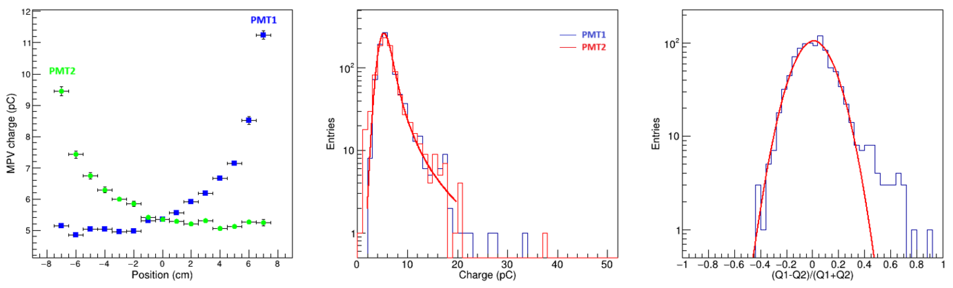
3. Counter Prototype Validation

A prototype validation campaign was performed to confirm that the scintillation photons produced by cosmic rays passing through the center of the counter were enough to provide trigger and energy deposit measurement. This is particularly important for the TR1 trigger detector, which was only 2 mm thick.
Six different types of scintillating counters are present in the HEPD-02 design as described in Section 2: TR1, TR2, RAN, EN, BOT, and LAT. Prototypes of each counter type were realized using the scintillating materials, wrapping, and PMTs selected for production.
The PMTs were read by electronic boards similar to the ones designed for the FM. While the counters were realized following procedures similar to the ones that were employed for the flight hardware, the supporting mechanics was adapted from the one readily available in the laboratory. The prototypes of the different counters are shown in Figure 2.
The prototypes were tested with a large scintillator tracker (NESSiE) available in the laboratory of INFN Bologna. NESSiE is composed of five planes, each one constituted of two orthogonal layers of scintillators, with a triangular cross-section able to reconstruct with high-efficiency tracks with inclinations up to 17 degrees and with a spatial resolution of 2 mm at the center [11]. The scintillation counter under test was placed inside a black box at the center of the NESSiE tracker. The PMT high voltages (HVs) were set to obtain a gain of 10 6 . NESSiE was used for triggering the acquisition of the counter under test read out by a CAEN digitizer V1751. Tracks were reconstructed using NESSiE information and then correlated with the two PMT-measured pulse heights and integrated charges. Off-time signals were used to evaluate the respective pedestals and noises. To accumulate enough statistics, the set-up for each counter was left in acquisition for a period of one to two weeks. The signals had a signal-to-noise ratio S / N > 10 in all positions along all the counters. In the case of TR1, a difference of 10 to 15 % between the two sides due to the asymmetry of the light guides was observed. This asymmetry does not have any impact on the trigger efficiency and can be compensated for with PMT equalization.
To test the trigger efficiency, a threshold of 20 mV was imposed [12] to signals on both sides of each counter. The trigger efficiency, derived with the logical OR of PMTs, is better than 95 % for all prototypes with good spatial uniformity.
The integrated charge measured from both the PMTs of the counter under study Q 1 , 2 was studied versus the impact position on the counter. For each position, the most probable value (MPV) of the signal distribution was calculated with a Landau distribution convoluted with a Gaussian. The two PMT responses were equalized to the MPV average at the center of the counter. In Figure 3, the equalized MPV charge registered by each one of the two PMTs of the TR1 counter under test as a function of the longitudinal coordinate, and the charge distribution observed at the center of the counter are shown.
The number of photo-electrons (p.e.) produced at the center of the counter can be derived directly from the measurement of the width of the distribution of the charge asymmetry ( Q 1 Q 2 ) / ( Q 1 + Q 2 ) , with the assumption that the signal is attenuated similarly at the location of the two PMTs, a condition that approximately holds for TR1, TR2, RAN, EN, and BOT. In the first approximation, the following relation can be derived:
N = 1 2 σ 2 .
where N is the number of photo-electrons detected at the PMT location, and σ is the width of the Gaussian fit of charge asymmetry distribution. The right-most image in Figure 3 presents the charge asymmetry of TR1 obtained for a sample of events passing through an area of 1   cm 2 at the center of the counter. The asymmetry distribution was fitted with a Gaussian, leading to an estimation of the number of the photo-electrons of N = ( 27 ± 1 ) p.e. in agreement with the expectations from the simulation.
The charge distributions and charge asymmetries were studied systematically for all counters (see Figures S2–S5 of the Supplementary Materials). In Table 2, the MPVs of the maximum signal amplitudes, integrated charges, and number of photo-electrons for impact positions in the middle of the counters are given. Counters TR2, RAN, EN, and BOT show amplitude signals and charges well above the TR1 ones. Due to its geometry and PMT location, the LAT has a very different signal dependence from transversal and longitudinal coordinates on the two sides. However, these signals are in magnitude well above the TR1 signal in all locations.

4. LYSO Crystal Characterization

To achieve a comprehensive characterization of the LYSO crystals manufactured by Filar-Optomaterials, a series of dedicated measurements was conducted [13]. These crystals constitute a novel product of the company developed specifically for HEPD-02, featuring non-standard dimensions that required careful crystal growth, cutting, and polishing, making it particularly crucial to meticulously understand their properties. The characterization of the crystals was conducted in three steps: (i) calibration of the energy response, (ii) estimation of the spectrum due to the intrinsic activity of Lutetium, and (iii) determination of the light response as a function of the particle impact point; the latter is discussed in Figure S6 of the Supplementary Materials.
Each crystal was characterized after being wrapped, and the response was recorded using two Hamamatsu R9880U-210 PMTs placed on opposite surfaces separated by the largest distance. A voltage of 700 V was applied to the PMTs to obtain a gain of about 4 × 10 5 . This characterization was performed for six crystals for the FM, six in the QM, and four spares. In the following sections, we provide a comparison of the sixteen samples.

4.1. Calibration of the Energy Response

The γ -ray emission at 1.333 MeV and 1.173 MeV of a 60Co sample was used to calibrate the crystals at low energies. The emitted radiation collected by LYSO crystals was measured using a trigger logic that required coincidence between the two PMTs of the LYSO crystal and a nearby NaI(Tl) detector. PMT signals were acquired using a Teledyne LeCroy HDO9104 oscilloscope (Marcon, Italy). For calibration at higher energies, two EJ-200 plastic scintillators with dimensions of 50   ×   30   × 10 mm 3 were placed above and below the crystal to trigger cosmic muons passing through the LYSO crystal. Minimum ionizing muons lose about 10 MeV/cm in LYSO, resulting in an energetic deposit of approximately 25 MeV for particles crossing the samples vertically. With the aid of the HEPD-02 direction detector [14,15], we evaluated the impact position and arrival direction of cosmic muons. By selecting the arrival angle of the muons, measurements were performed between 25 and 30 MeV. Measurements of the amplitude distribution MPV for muons and 60Co allowed us to perform the calibration illustrated in Figure 4. All crystals showed similar calibration factors.

4.2. Estimation of the Spectrum Due to the Intrinsic Activity of Lutetium
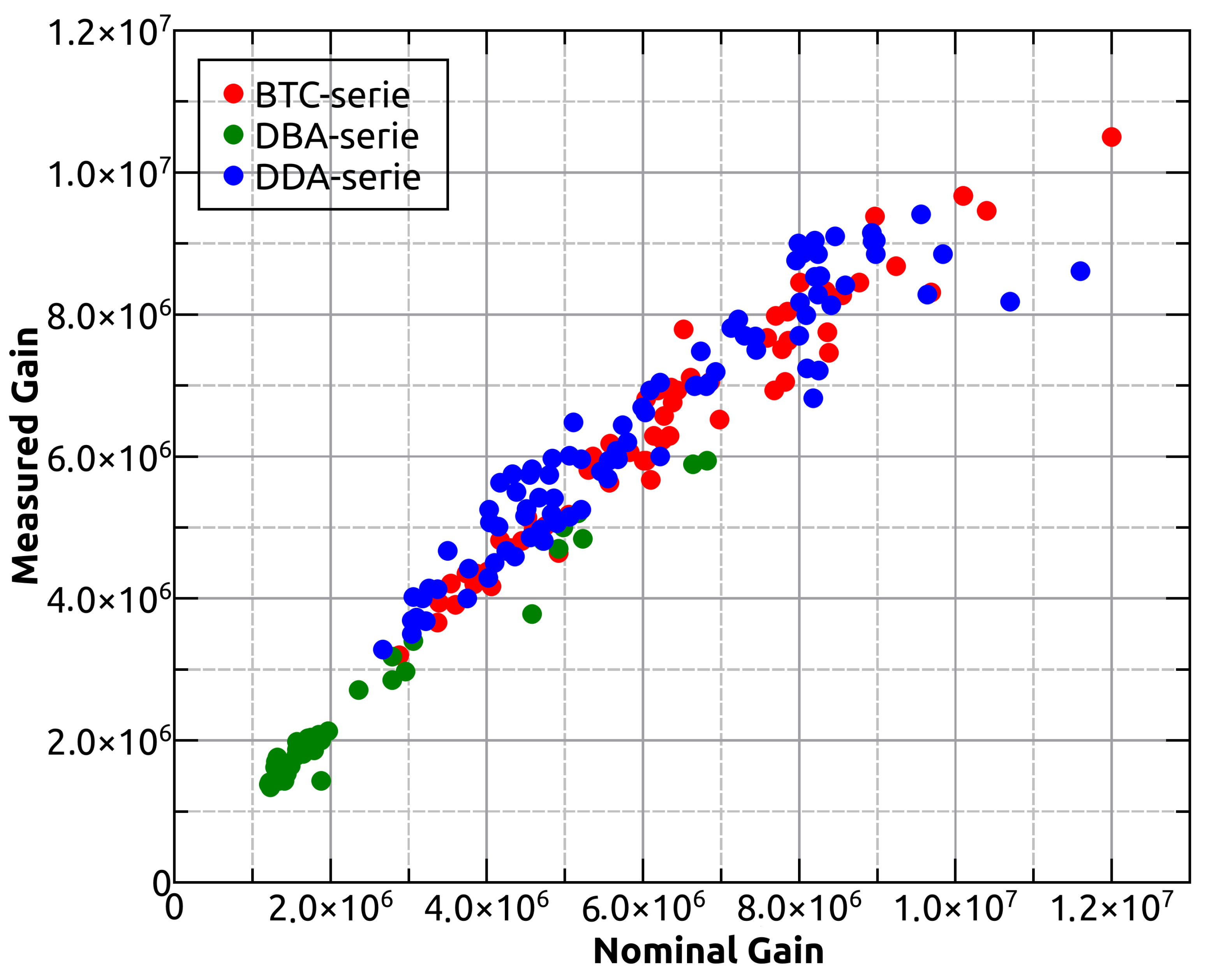
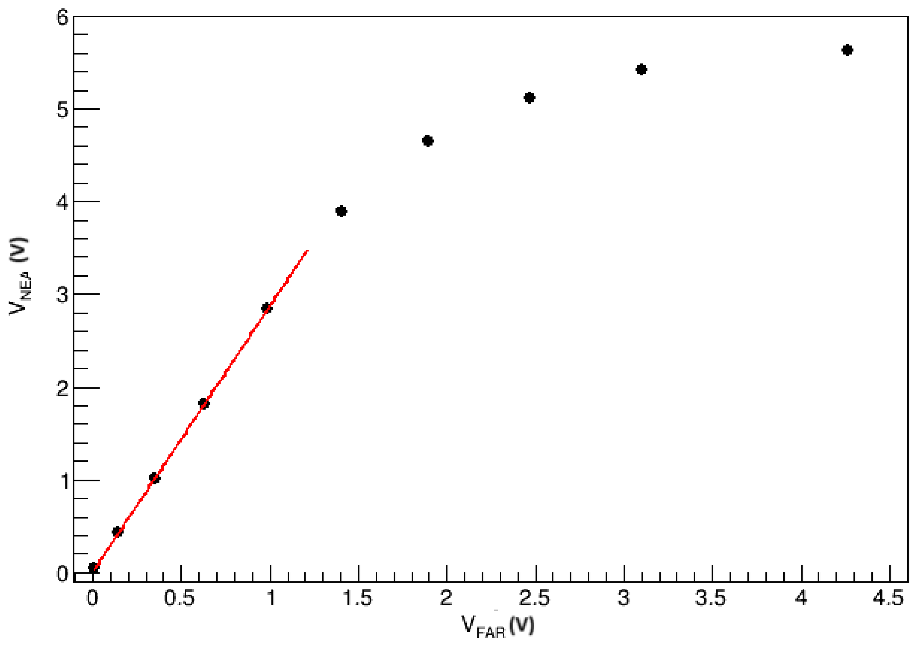
LYSO contains natural Lutetium, which comprises approximately 2.6% of the radioactive isotope 176Lu. This material is subject to an intrinsic radioactive background due to the decay of 176Lu via β -emission, with a half-life of 3.76 × 10 10 years. The mean and maximum emitted β energies are 182 keV and 593 keV, respectively, and the decay generates excited states of the daughter isotope 176Hf, which produces a chain of three γ -rays with energies of 88, 202, and 307 keV. This intrinsic radiation results in a spectrum consisting of four peaks at 88, 88 + 202, 88 + 307, and 88 + 202 + 307 keV, depending on the probability of one or more photons escaping the crystal. Extensive Monte Carlo simulations of the intrinsic radioactive spectrum are reported in the literature [16]. The measurement was performed using a trigger logic with the two PMTs coupled to the LYSO crystals in coincidence, employing signal thresholds in the mV range. The amplitude distribution obtained can be described by a Gaussian shape with an exponential tail, representing the convolution of the four γ lines and the β -decay radiation (see Figure 5). The measured rate was consistent with the LYSO total activity of approximately 40 Bq/g [17]. This measurement is essential for establishing the HEPD-02 experiment’s calorimeter thresholds, which should be kept as low as possible to detect the high-end of GRB spectra while keeping a manageable rate coming from a 176Lu intrinsic background [7]. Figure 5 reports the photo-electron MPVs measured in the LYSO samples created by the decay of 176Lu.

5. PMT Calibration

The PMTs selected for HEPD-02 are the Hamamatsu R9880U-210. These PMTs are characterized by high gain, a fast time response, and a high quantum efficiency in the range of wavelengths of our scintillators (see Hamamatsu R9880U-series PMT datasheet, https://www.hamamatsu.com/content/dam/hamamatsu-photonics/sites/documents/99_SALES_LIBRARY/etd/R9880U_TPMH1321E.pdf, accessed on 20 October 2024).
In total, 128 PMTs were needed for the integration of the QM and FM of HEPD-02. In each one of the two detectors, the 64 PMTs were powered by 16 HV lines. To perform the best possible matching of the PMTs with the different scintillation counters that have widely different numbers of photons produced by MIPs and which PMTs should be powered on the same HV line, a detailed characterization of the PMTs’ gain versus the HV was realized. The procedure also allowed for the discrimination of non-functional PMTs, and verification of the nominal characteristics provided by Hamamatsu. Globally, 200 PMTs were tested.
The method applied to calculate the gain of a PMT follows the method of photo-statistics [18]. In short, the PMT is placed inside a black box and is illuminated with different light intensities emitted from a LED controlled in voltage. For each LED intensity, the mean observed signal R is related to the number of photo-electrons emitted by the photo-cathode N by the gain factor G, or R = G N . The variance of the observed signal σ R has essentially three contributions, (i) the Poisson statistics of the photo-emission process, (ii) the variance of the single photo-electron distribution δ spe , and (iii) electronic noise. The LED intensities used in the tests are such that the electronic noise is always negligible with respect to σ R . We can write
σ R 2 = G ( 1 + δ spe 2 ) R .
By testing the PMT with different LED intensities, the σ R 2 versus R curve allowed for the derivation of the term G ( 1 + δ spe 2 ) . To derive the gain G, the needed δ spe was derived by fitting the single-photon distribution that was obtained using very low intensity on the LED with the PMT set at a reference voltage of 1000 V. To study the dependence of the PMT gain from the HV, the procedure was repeated several times for different voltages from 600 to 1000 V. Examples of the calibration procedure are given in Figures S7–S9 of the Supplementary Materials. The procedure was repeated for all PMTs in bunches of four.
A comparison of the gain measured to the nominal one given by Hamamatsu at 1000 V is given in Figure 6. The PMTs tested were found to have gains ranging from 10 6 to 10 7 and are within 20% with respect to the nominal gains provided by Hamamatsu.
As observed in Section 3, different scintillators have a very different response in terms of produced scintillation light. To ensure that the PMTs responses matched well with the scintillator response, gains reported in Table 3 were considered as a baseline PMT target configuration. For each group of counters, starting from the group with the lowest expected signal (TR1) to the one with the highest signal (EN), we calculated the HV needed by all the PMTs to obtain the target gain based on the calibration. Then, we assigned the PMTs with the lowest HV to the considered group, assigning PMTs to the FM and the QM while trying to keep the variance of the HV of each model within 20%. The assigned PMTs were removed from the list and the procedure was repeated group by group. For each group, a few PMTs were put aside as spares. Finally, the PMTs assigned to each line of the FM and QM had a gain within 12%, while the gain difference was <5% for PMTs assigned to the same counter.
There are different methods of measurement of the linearity for PMTs as described in [19]. In this work, non-linearities in the response of the PMTs are tested by comparing the PMT response at two different distances from the LED (55, 110 mm) versus the LED intensity [20]. In Figure 7, a non-linear behavior above V NEAR = 3.5 V is observed, where a value of V NEAR exceeds 10% of the extrapolation of the linear fit performed on V NEAR versus V FAR , in the range from 0 to 1.3 V.

6. Simulation

Monte Carlo simulations based on the GEANT4 toolkit [21] were developed for each scintillation counter type. GEANT4 is a framework for the simulation of the passage of particles through matter, including electromagnetic, hadronic, and optical interactions. The simulations take into account the propagation and energy release by the incident particle in the sensitive detectors, the production of optical photons, and their propagation in the material up to the interface with the PMTs. The light emission spectra of plastic scintillators (EJ-200) and crystals (LYSO) and the PMT’s quantum efficiency as a function of the wavelength were also included in the simulation. For each incident event, the charge collected at each end of a counter was obtained by integrating the total number of photo-electrons converted at the surface of the PMT photocathodes and by multiplying the PMT gain. The absorption coefficients of the materials and the reflectivity of the wrapper were set as free parameters to be adjusted to match experimental results. The absorption length was found to be ∼ 380 cm for plastic scintillators and ∼ 300 cm for LYSO crystals, whereas the reflectivity was found to range from 97% to 98%.
Longitudinal profiles and bi-dimensional maps of the MPV and the mean number of photo-electrons recorded by the PMTs were reconstructed against the incident position and then compared to the experimental data discussed in Section 3. In Figure 8, the simulated MPV profile is compared with experimental data for the TR1 scintillator bar. Figure 9 shows a comparison between the data (top) and simulation (bottom) of bi-dimensional maps of the mean relative charge to the center of the bar recorded by one of the TR1 phototubes versus the position expressed in 5 × 15 bins along the (transversal × longitudinal) dimensions. The simulation results agree with the data within 20%. The remaining discrepancy is probably due to the fact that the simulation considers perfect surfaces and optical contacts as well as constant reflectivity, i.e., independent of the wavelength. For the other counters, TR2, RAN and EN, the simulation has an agreement of better than 10%. The comparison between data and simulation are presented in Figures S10–S18 of the Supplementary Materials.

7. Conclusions

In this paper, the design and performance of the HEPD-02 scintillation counters are reviewed. The results obtained from testing them with cosmic muons and an external tracking system show that prototypes of the counters have an efficiency >95% and excellent signal uniformity, matching with the expectations of the HEPD-02’s overall design. The LYSO counters were carefully characterized using radioactive sources and the intrinsic Lutetium radiation. A set of 200 PMTs, over the needed 128, were characterized for a wide range of HVs. Taking into account the difference in the number of photo-electrons of each counter, and the fixed number of (16) HV channels in HEPD-02, the PMTs were grouped to have similar gain onto the same HV channel. The mean HVs per channel were also optimized to match the desired signal amplitude per counter type, ensuring that PMTs at both ends of the same counter were approximately equalized. The PMTs were chosen to provide the target gains at the low end of the HV working range to possibly compensate for degradation over time with HV tuning. Comparison of the performances based on test prototypes and preliminary GEANT4 simulation show an agreement within 20%. The HEPD-02 full simulation is based on these results [22,23].

Supplementary Materials

The following supporting information can be downloaded at: https://www.mdpi.com/article/10.3390/rs16213982/s1.

Author Contributions

Conceptualization, investigation, methodology, data curation, software, visualization, and writing—original draft preparation, A.L., M.L., F.N., A.O., F.P. (Federico Palmonari), M.P. and Z.S.; writing—review and editing, S.B. (Simona Bartocci), R.B., S.B. (Stefania Beolè), F.B., P.C., S.C., A.C., M.C., C.D.D., C.D.S., A.D.L., F.D., F.M.F., S.G.B., G.G., R.I., A.L., M.L., G.M., M.M. (Matteo Mergè), M.M. (Marco Mese), R.N., F.N., A.O., G.O., F.P. (Francesco Palma), F.P. (Federico Palmonari), B.P., S.P., F.P. (Francesco Perfetto), P.P., M.P., E.R., M.R., S.B.R., Z.S., U.S., V.S., E.S., A.S., R.S., P.U., V.V., S.Z. and P.Z.; supervision, project administration, and funding acquisition, R.B., A.C., C.D.S., R.I., P.P., R.S. and S.Z. All authors have read and agreed to the published version of the manuscript.

Funding

This research was supported by the Italian Space Agency (ASI) in the framework of the “Accordo attuativo 2019-22-HH.0 Programma Limadou-2 attività di fase B2/C/D/E1” and the ASI-INFN agreement no. 2021-43-HH.0.

Data Availability Statement

Reported results can be found at https://figshare.com/account/home#/projects/216307, accessed on 20 October 2024.

Conflicts of Interest

The authors declare no conflicts of interest.

Abbreviations

The following abbreviations are used in this manuscript:
BOTBottom containment panel
CSESChina Seismo-Electromagnetic Satellite
DIRDirection Detector
ENEnergy Detector
FMFlight Model
GEANT4Geometry and Tracking
GRBsGamma-Ray Bursts
HEPDHigh-Energy Particle Detector
HVHigh Voltage
LATLateral Containment Panel
LEDLight-Emitting Diode
LYSOCerium-doped Lutetium–Yttrium Oxyorthosilicate ( Lu 2 ( 1 x ) Y 2 x SiO 5 :Ce)
MAPSsMonolithic Active Pixel Sensors
MPVMost Probable Value
NESSiENeutrino Experiment with Spectrometers in Europe
p.e.photo-electron
PMTsPhotomultiplier Tubes
PMMAPolymethyl Methacrylate
QMQualification Model
RANRange Detector
TR1Trigger Detector 1st plane
TR2Trigger Detector 2nd plane

References

  1. Shen, X.; Zhang, X.; Yuan, S.; Wang, L.; Cao, J.; Huang, J.; Zhu, X.; Picozza, P.; Dai, J. The state-of-the-art of the China Seismo-Electromagnetic Satellite mission. Sci. China Tech. Sci. 2018, 61, 634. [Google Scholar] [CrossRef]
  2. Picozza, P.; Battiston, R.; Ambrosi, G.; Bartocci, S.; Basara, L.; Burger, W.J.; Campana, D.; Carfora, L.; Casolino, M.; Castellini, G.; et al. Scientific Goals and In-Orbit Performance of the High-Energy Particle Detector on Board the CSES. Astrophys. J. Supp. Ser. 2019, 243, 16. [Google Scholar] [CrossRef]
  3. Martucci, M.; Sparvoli, R.; Bartocci, S.; Battiston, R.; Burger, W.J.; Campana, D.; Carfora, L.; Castellini, G.; Conti, L.; Contin, A.; et al. Trapped Proton Fluxes Estimation Inside the South Atlantic Anomaly Using the NASA AE9/AP9/SPM Radiation Models along the China Seismo-Electromagnetic Satellite Orbit. Appl. Sci. 2021, 11, 3465. [Google Scholar] [CrossRef]
  4. Martucci, M.; Laurenza, M.; Benella, S.; Berrilli, F.; Del Moro, D.; Giovannelli, L.; Parmentier, A.; Piersanti, M.; Albrecht, G.; Bartocci, S.; et al. The First Ground-Level Enhancement of Solar Cycle 25 as Seen by the High-Energy Particle Detector (HEPD-01) on Board the CSES-01 Satellite. Space Weather 2023, 21, e2022SW003191. [Google Scholar] [CrossRef]
  5. Palma, F.; Martucci, M.; Neubüser, C.; Sotgiu, A.; Follega, F.M.; Ubertini, P.; Bazzano, A.; Rodi, J.C.; Ammendola, R.; Badoni, D. Gamma-Ray Burst Observations by the High-Energy Particle Detector on Board the China Seismo-Electromagnetic Satellite Between 2019 and 2021. Astrophys. J. 2024, 960, 21. [Google Scholar] [CrossRef]
  6. Ricci, E.; on behalf of the Limadou Collaboration. A pixel based tracker for the HEPD-02 detector. In Proceedings of the 38th International Cosmic Ray Conference (ICRC2023), Nagoya, Japan, 26 July–3 August 2023. PoS (ICRC2023) 058. [Google Scholar] [CrossRef]
  7. Lega, A.; Follega, F.M.; Iuppa, R.; Mese, M.; Nicolaidis, R.; Nozzoli, F.; Ricci, E.; Sotgiu, A.; Vilona, V.; Zuccon, P. on behalf of the Limadou-HEPD Collaboration. Exploring the Efficiency of HEPD-02 LYSO:Ce Scintillators in the CSES-02 Satellite Mission for Detecting Gamma-Ray Bursts. In Proceedings of the 38th International Cosmic Ray Conference (ICRC2023), Nagoya, Japan, 26 July–3 August 2023. PoS (ICRC2023) 758. [Google Scholar] [CrossRef]
  8. Lega, A.; Follega, F.M.; Gebbia, G.; Iuppa, R.; Nozzoli, F. Study on the homogeneity of large-size LYSO:Ce crystals for the HEPD-02 electromagnetic calorimeter. Il Nuovo Cimento C 2023, 46, 118. [Google Scholar] [CrossRef]
  9. De Santis, C.; Ricciarini, S.; on behalf of the CSES-Limadou Collaboration. The High Energy Particle Detector (HEPD-02) for the Second China Seismo-Electromagnetic Satellite (CSES-02). In Proceedings of the 37th International Cosmic Ray Conference (ICRC2021), Online, 15–22 July 2021. PoS (ICRC2021) 058. [Google Scholar] [CrossRef]
  10. Scotti, V.; on behalf of the CSES-Limadou Collaboration. Trigger and data acquisition system of the High Energy Particle Detector on board the CSES-02 satellite. Nucl. Instrum. Methods Phys. Res. A 2023, 1046, 167741. [Google Scholar] [CrossRef]
  11. Bernardini, P.; Cecchini, S.; Cindolo, F.; D’Antone, I.; Degli Esposti, L.; Fiore, G.; Lax, I.; Mandrioli, G.; Marsella, G.; Mauri, N.; et al. On the performances of a particle tracking detector based on triangular scintillator bars read out by silicon photomultipliers. Nucl. Instrum. Methods Phys. Res. A 2020, 967, 163882. [Google Scholar] [CrossRef]
  12. Mese, M.; Anastasio, A.; Boiano, A.; Masone, V.; Vanzanella, A.; Bartocci, S.; Battiston, R.; Benotto, F.; Beolé, S.; Burger, W.; et al. The HEPD-02 trigger and PMT readout system for the CSES-02 mission. In Proceedings of the 37th International Cosmic Ray Conference (ICRC2021), Online, 15–22 July 2021. PoS (ICRC2021) 063. [Google Scholar] [CrossRef]
  13. Lega, A. Large-Size LYSO:Ce Crystals for Electromagnetic Calorimetry in Space: Qualification and Characterisation of the HEPD-02 Energy Detector. In Proceedings of the 2022 IEEE Nuclear Science Symposium and Medical Imaging Conference (NSS/MIC), Milano, Italy, 5–12 November 2022; pp. 1–5. [Google Scholar] [CrossRef]
  14. Ricciarini, S.B.; Beolè, S.; de Cilladi, L.; Gebbia, G.; Iuppa, R.; Ricci, E.; Zuccon, P. Enabling low-power MAPS-based space trackers: A sparsified readout based on smart clock gating for the High Energy Particle Detector HEPD-02. In Proceedings of the 37th International Cosmic Ray Conference (ICRC2021), Online, 15–22 July 2021. PoS (ICRC2021) 71. [Google Scholar] [CrossRef]
  15. Savino, U.; CSES-Limadou Collaboration. Expected performance of the High Energy Particle Detector (HEPD-02) tracking system on board of the second China Seismo-Electromagnetic Satellite. Nucl. Instrum. Methods Phys. Res. A 2024, 1063, 169281. [Google Scholar] [CrossRef]
  16. Alva-Sanchez, H.; Zepeda-Barrios, A.; Díaz-Martínez, V.D.; Murrieta-Rodríguez, T.; Martínez-Dávalos, A.; Rodríguez-Villafuerte, M. Understanding the intrinsic radioactivity energy spectrum from 176Lu in LYSO/LSO scintillation crystals. Sci. Rep. 2018, 8, 17310. [Google Scholar] [CrossRef] [PubMed]
  17. Enríquez-Mier-y-Terán, F.E.; Ortega-Galindo, A.S.; Murrieta-Rodríguez, T.; Rodríguez-Villafuerte, M.; Martínez-Dávalos, A.; Alva-Sánchez, H. Coincidence energy spectra due to the intrinsic radioactivity of LYSO scintillation crystals. EJNMMI Phys. 2020, 7, 21. [Google Scholar] [CrossRef] [PubMed]
  18. Bencheikh, B.; DeSalvo, R.; Hao, W.; Xu, C.; You, K. A simple light detector gain measurement technique. Nucl. Instrum. Methods Phys. Res. A 1992, 315, 349–353. [Google Scholar] [CrossRef]
  19. Hamamatsu Photonics. Photomultiplier Tubes: Basics and Applications, 4th ed.; Hamamatsu Photonics: Hamamatsu, Japan, 2017; Available online: https://www.hamamatsu.com/content/dam/hamamatsu-photonics/sites/documents/99_SALES_LIBRARY/etd/PMT_handbook_v4E.pdf (accessed on 20 October 2024).
  20. Wang, X.; Qian, X.-L.; Yu, Y.-H.; Feng, C.-F.; Martineau-Huynh, O.; Zhang, Y.; Gou, Q.-B.; Liu, W.; Feng, Y.-L. Characterization of the photomultiplier tubes for the scintillation detectors of GRANDProto35 experiment. JINST 2021, 16, P04008. [Google Scholar] [CrossRef]
  21. Agostinelli, S.; Allison, J.; Amako, K.; Apostolakis, J.; Araujo, H.; Arce, P.; Asaii, M.; Axen, D.; Banerjee, S.; Barrand, G.; et al. Geant4—A simulation toolkit. Nucl. Instrum. Methods Phys. Res. A 2003, 506, 250. [Google Scholar] [CrossRef]
  22. Sahnoun, Z.; Follega, F.M.; Iuppa, R.; Oliva, A.; Pozzato, M.; Ricci, E.; on behalf of the CSES-Limadou Collaboration. Expected performance of the High-Energy Particle Detector on-board the second China Seismo-electromagnetic Satellite. In Proceedings of the 37th International Cosmic Ray Conference (ICRC2021), Online, 15–22 July 2021. PoS (ICRC2021) 072. [Google Scholar] [CrossRef]
  23. Contin, A.; Di Luca, A.; Follega, F.M.; Iuppa, R.; Lolli, M.; Oliva, A.; Palmonari, F.; Pozzato, M.; Ricci, E.; Sahnoun, Z. on behalf of the CSES-Limadou Collaboration. GEANT4 simulation strategy and event reconstruction for HEPD-02 detector onboard the CSES-02 Satellite. In Proceedings of the 38th International Cosmic Ray Conference (ICRC2023), Nagoya, Japan, 26 July–3 August 2023. PoS (ICRC2023) 148. [Google Scholar] [CrossRef]
Figure 1. An exploded view of the HEPD-02 detector, from left to right: the two trigger planes (TR1 and TR2) with the direction detector (DIR) in between, one of the lateral containment panels (LAT), the two LYSO crystal planes (EN), the bottom containment panel (BOT), and the plastic scintillator tower (RAN) [9].
Remotesensing 16 03982 g001
Figure 2. Pictures of the counter prototypes under study. On the top–left panel, the trigger plane counters (TR1 and TR2) are shown. On the top–right, a calorimeter tile (RAN) is displayed. One of the LYSO crystals (EN) and a prototype of the lateral containment panel (LAT) are shown on the bottom–left and right panels, respectively. Each prototype contains a scintillating volume (either LYSO or plastic) of different dimensions, wrapped in aluminized Mylar to reflect the light produced by cosmic rays passing through the scintillator, guiding it toward the edges of the volume. The light is collected by two PMTs, positioned on opposite sides of each prototype, and coupled to the scintillator through optical pads. As shown in the top–left figure, the TR1 counter also features trapezoidal light guides.
Remotesensing 16 03982 g002
Figure 3. On the left, the MPV charge recorded by the two PMTs versus the longitudinal coordinate is presented. The behavior of the MPV versus the longitudinal coordinate provides a direct measurement of the uniformity of the response. In the middle, the equalized PMT charge distributions for a sample of tracks passing through the center of the counter are presented. The amount of collected charge is enough to trigger at least one of the sides of the counter in any position. On the right, the charge asymmetry distribution for the same sample is presented. This distribution is used to directly estimate the number of photons generated for a particle passing through the middle of the counter.
Remotesensing 16 03982 g003
Figure 4. The left panel displays the energy calibration line for one PMT of a given sample derived from the measurement described in Section 4.1, accompanied by a ratio plot depicting the relationship between the fitted line and the measured points. The constant of the fitted line is considered to be zero. On the right, the slopes of the sixteen crystals (i.e., the energy calibration factors obtained from the fit in the left figure) are presented in three histograms, where the y-axis represents the number of crystals with the same calibration factor within the error bars. The histograms are for the different groups, from top to bottom: FM group, QM group, and spare group, respectively. The means of the histograms for the three different groups are statistically compatible within one standard deviation. These values represent the arithmetic mean of measurements obtained from the two PMTs associated with each crystal.
Remotesensing 16 03982 g004
Figure 5. The left panel illustrates the intrinsic radioactivity spectrum generated by 176Lu as measured in a laboratory test by one PMT in a single LYSO sample. On the right panel, the distribution of MPV of the spectrum is depicted for each group of crystals, from top to bottom: FM group, QM group, and spare group, respectively. These reported values represent the arithmetic mean of measurements obtained from the two PMTs associated with each crystal.
Remotesensing 16 03982 g005
Figure 6. The measured gain versus nominal gain for the total bunch of PMTs tested at an HV of 1000 V. The different colors refer to different PMT productions.
Remotesensing 16 03982 g006
Figure 7. The PMT signal amplitude at near position (55 mm) versus the amplitude in far position (110 mm). The red line is a fit to data in the range from 0 to 1.3 V in V FAR .
Remotesensing 16 03982 g007
Figure 8. The MPV of photo-electrons recorded by each PMT versus the longitudinal position for TR1 counter.
Remotesensing 16 03982 g008
Figure 9. A bi-dimensional map of the mean charge relative to the center recorded by one of the PMTs versus the impact position for the TR1 counter. At the top is the map from the experimental data. At the bottom is the one from the simulation.
Remotesensing 16 03982 g009
Table 1. A summary of the technical and scientific requirements of HEPD-02.
Operating temperature−10 °C ÷ +35 °C
Operating pressure≤6.65 · 10 3 Pa
Power Budget≤45 W
Mass Budget≤50 kg
Data Budget≤100 Gbit/day
Life Cycle>6 years
Kinetic Energy Range for e3 MeV ÷ 100 MeV
Kinetic Energy Range for p30 MeV ÷ 200 MeV
Energy Resolution≤10% for e with E > 5 MeV
Table 2. For each counter sample, the following quantities are derived: (i) the MPV of the signal maximum amplitude, (ii) the MPV of the integrated charge, and (iii) the mean number of photo-electrons for a sample of minimum ionizing cosmic muons passing through an area of 1   cm 2 around the center of the counter. A correction for the difference in photon transmission due to the light guides in TR1 is included.
CounterAmplitude (mV)Charge (pC)N (p.e.)
TR1 43.7 ± 0.7 5.31 ± 0.06 27 ± 1
TR2 221.1 ± 1.5 35.1 ± 0.2 197 ± 4
RAN 114 ± 11 29.9 ± 0.1 130 ± 2
EN 513 ± 29 477 ± 27 2986 ± 194
Table 3. The target PMT gain assigned to the different counter types.
CounterGain
TR1-LAT3 ×  10 6
TR2-RAN-BOT 10 6
EN5 ×  10 5
Disclaimer/Publisher’s Note: The statements, opinions and data contained in all publications are solely those of the individual author(s) and contributor(s) and not of MDPI and/or the editor(s). MDPI and/or the editor(s) disclaim responsibility for any injury to people or property resulting from any ideas, methods, instructions or products referred to in the content.

