Article

A Coherent Integration Method for Moving Target Detection in Frequency Agile Signal-Based Passive Bistatic Radar

1
Guangzhou Institute of Technology, Xidian University, Guangzhou 510555, China
2
School of Microelectronics Science and Technology, Sun Yat-sen University, Zhuhai 519082, China
3
National Key Laboratory of Electromagnetic Space Security, Chengdu 610036, China
*
Author to whom correspondence should be addressed.
Remote Sens. 2024, 16(7), 1148; https://doi.org/10.3390/rs16071148
Submission received: 1 February 2024 / Revised: 19 March 2024 / Accepted: 21 March 2024 / Published: 26 March 2024
(This article belongs to the Special Issue Target Detection, Tracking and Imaging Based on Radar)

Abstract

:
In this paper, the possibility of improving target detection performance in passive bistatic radar by exploiting a frequency agile (FA) signal is investigated, namely frequency agile signal-based passive bistatic radar (FAPBR) coherent integration. Since the carrier frequency of each pulse signal is agile, FAPBR coherent integration suffers from the problems of random range and Doppler phase fluctuations. To tackle these challenges, a novel FA signal coherent integration target detection scheme for PBR is proposed. In particular, the phase quadratic difference principle is presented for eliminating Doppler phase hopping. Then, frequency rearrangement is adopted to compensate for random range phase fluctuation while obtaining the high-range-resolution profiles (HRRPs) of the detecting target. Further, we innovatively present a sliding-range ambiguity decoupling (S-RAD) method to remove the range ambiguity effect in the case of the high pulse repetition frequency (HPRF). Compared with the existing methods, the proposed method can effectively mitigate Doppler phase hopping without requiring prior target velocity information, offering improved coherent integration performance in frequency agile signals with reduced computational complexity. Moreover, it successfully corrects the range ambiguity issue caused by HPRF. Finally, a series of simulation results are presented to demonstrate the effectiveness of the proposed algorithm.

1. Introduction

Passive bistatic radar (PBR) exploits non-cooperative illuminators of opportunity (IOs) to detect moving targets and has received increasing attention in recent years [1,2,3]. Since the absence of dedicated transmitter equipment, PBR offers many advantages over conventional monostatic active radars, such as contained cost and low maintenance, covert detection, and anti-jamming [4,5,6,7]. With tremendous advances in hardware and signal-processing technology, PBRs are extensively deployed for air traffic control, coastal/maritime protection, and terrestrial vehicle surveillance [8,9]. In addition, another advantage is derived from the geometry of the passive radar system, because it is bistatic. The bistatic radar cross-section (RCS) of a target is different from its monostatic RCS, and this will aid target detection and classification. With tremendous advances in hardware and signal-processing technology, PBRs are extensively deployed for air traffic control, coastal/maritime protection, and terrestrial vehicle surveillance [8,9]. At present, a variety of IOs, such as frequency modulation (FM) [10,11], digital television terrestrial multimedia broadcasting (DTMB) [12,13], long-term evolution (LTE) [14], WiFi [15] and global navigation satellite system (GNSS) [16,17,18], are suitable for PBR systems because of their close-to-ideal ambiguity function. Additionally, due to the high power (FM, DTMB), wide bandwidth (LTE), high carrier frequency, and easy accessibility (WiFi) of these signal sources, they have been extensively used in airspace target warning, sea target detection, low-altitude drone monitoring, and indoor safety applications, garnering significant interest from radar researchers. However, these IOs are oriented towards civil or commercial services and are not applicable in specific military scenarios.
To fully exploit the detection potential of the PBR system, an effective solution is to “make use of local resources”, which means utilizing the military navigation and communication signals, such as the Joint Tactical Information Distribution System (JTIDS) [19,20,21] for target sensing. In particular, for the sake of obtaining excellent electronic counter-countermeasure (ECCM) performance, these signals always have the characteristics of frequency agility (FA) and a high pulse repetition frequency (HPRF) [22]. Specifically, in an FA signal, the carrier frequency of each pulse is randomly selected from a given set of available frequencies, which are distributed on a continuous frequency band at equal frequency step intervals. Thus, the FA signal can synthesize a wider bandwidth coherently to obtain high-range resolution profiles (HRRPs) for radar systems [23].
In the radar field, the surveillance radar requires high system gain to realize long-range target detection. PBRs also need a high system gain for wide zone coverage [24]. However, the entire transmitter parameters are beyond the control of the system designer, including the antenna gain, the power, and the bandwidth [25]. Therefore, PBR systems usually face the problem of short-range detection and poor range resolution performance. To improve the reliability of the PBR system, coherent and non-coherent integration techniques are usually considered. The coherent integration method can significantly improve the energy level of the signal, whereas the strict phase relationship among the signals is required [26,27]. In contrast, incoherent integration has wider applications as its implementation only requires accumulating the signal’s amplitude following envelope demodulation [28]. However, the detection performance is limited due to the fact that the phase information is not considered. Therefore, to achieve the ideal detection performance, it is essential to carry out the research of coherent integration.
However, since the carrier frequency is agile in FA signals, there are some challenges in implementing these systems. (1) Doppler migration: since the Doppler information of a moving target depends on the carrier frequency of the transmitted signal, the phases of target signals in different pulses are not coherent [29,30]. Thus, Doppler migration occurs during FA signal coherent integration. Moreover, the faster the speed, the worse the coherence between FA signals. For better detection performance, the Doppler phase difference between each pulse must be estimated and compensated before coherent accumulation. (2) Range phase incoherence: while a broadband signal can be synthesized from an FA signal, the agile frequency will cause range phase fluctuation since the range phase and agile carrier frequency are coupled [31]. That is, the target range phase is completely incoherent in FAPBRs owing to the randomly varying carrier frequency which destroys signal coherence properties and causes a mismatching phenomenon. Further, the HPRF characteristic not only brings a low probability of intercept but also leads to a severe range ambiguity effect. This will directly deteriorate the detection range of the FAPBR system and thereby make traditional coherent integration methods, such as range-Doppler processing (RDP), invalid [32].
In view of the above-mentioned problems, researchers have made many contributions to improving the detection performance of FA radars. Specifically, for the Doppler migration problem, the method proposed in [33] utilizes twiddle factor reconstruction according to the frequency hopping pattern to estimate target Doppler information and eliminate the Doppler migration. However, this method ignores the phase term produced by the initial target range in the down-convert processing. Moreover, a large amount of calculation is required because the fast Fourier transform (FFT) is not applicable. Additionally, a hybrid integration method is presented in [34]. In this method, moving target detection (MTD) is first performed on the pulses with the same frequency, and then the coherent integration results of different frequency bands are incoherently accumulated. While the hybrid integration method can improve the system gain, the performance depends on the pulse numbers with the same frequency. Further, many researchers have also proposed a compressed sensing (CS) technique to extract target parameters of FA radar [35,36,37]. By exploiting the sparseness of the target scenario, i.e., a target usually consists of a few scatterers, the CS technique promises to reconstruct the target Doppler information as long as the so-called dictionary matrix satisfies the restricted isometry property (RIP). However, such methods ignore the influence of range phase non-coherence and require significant computing overhead.
For addressing the range phase incoherence problem, there are some methods as follows. First of all, the FA signal can be regarded as a randomized stepped-frequency signal to some extent. In stepped-frequency radar, a common method to achieve coherent integration is realized by utilizing an inverse fast Fourier transform (IFFT) after velocity compensation. However, in an FA signal, the sequence of stepped-frequency signals is randomized, so HRRP generation via IFFT is no longer applicable. To address the issue of IFFT failure, an intuitive method is to reconstruct the twiddle factor of the IFFT according to the frequency hopping pattern. However, this requires expensive computational complexity. To solve this problem, the joint zero-padding (JZP) method is proposed in [38], which utilizes pulse reordering and the zero-padding IFFT to generate HRRPs. Moreover, sidelobe suppression filtering is also proposed to eliminate range phase incoherence and generate HRRPs based on convex optimization [39]. Although these methods are capable of integrating an FA signal coherently, they all assume that the velocity information of the target is known a priori, which is an ideal assumption in a real radar system. Finally, the range ambiguity problem caused by the HPRF is not considered in the above algorithms, which seriously limits the detection range of the system.
To address the aforementioned problems and obtain the coherent integration of the FAPBR system, we proposed the following strategy: The FAPBR signal models are first constructed and analyzed. Then, the phase quadratic difference principle is presented to rapidly estimate the Doppler frequency and correct the hopping Doppler phase. After that, according to the hopping pattern of carrier frequency, frequency rearrangement is adopted to compensate for random range phase fluctuation while generating the HRRPs of the detecting target. Further, a sliding range ambiguity decoupling (S-RAD) method is presented to remove the range ambiguity effect in the case of the HPRF. Finally, a series of simulation results are presented to demonstrate the effectiveness of the proposed methods.
The main contributions of this paper are given as follows:
(1)
An observation model that describes the received signals in terms of the FAPBR system is established and analyzed. Subsequently, a novel target detection algorithm with FA signal coherent integration for passive bistatic radar is proposed for realizing long-range detection and obtaining finer range resolution. In particular, this paper gives a detailed scheme process and algorithm steps, thereby extending the application of PBR.
(2)
This paper develops the phase quadratic difference to effectively eliminate the Doppler phase hopping induced by agile carrier frequency. In comparison with the existing methods, the proposed method can mitigate the Doppler migration without the assistance of prior information on the target velocity. Moreover, the method is suitable for multi-target scenarios, and, therefore, has wider applicability and convenience.
(3)
This paper adopts frequency reordering, i.e., pulse signal reordering, to generate the HRRPs of a target while suppressing the random range phase fluctuation caused by randomized stepped frequencies. Additionally, to address range ambiguity resulting from the HPRF during FA signal coherent integration, this paper introduces the S-RAD method to extend the system’s detection range.

2. Signal Model and Problem Analysis

2.1. Signal Model

A typical PBR system consists of two sets of antennas (shown in Figure 1), a reference and a surveillance antenna. The reference antenna is used to collect the reference signal transmitted from the illuminator; the surveillance antenna is directed toward the monitored airspace to collect the target echo signal [40]. The target echo is always contaminated by direct path interference (DPI) from the transmitter and the multipath clutter reflected by the buildings [41]. The work of this paper is aimed at the field of coherent integration, so we assume that both DPI and multipath clutter have been eliminated before coherent integration.
We suppose that the transmitted signal is the minimum shift keying (MSK) modulated FA signal and the modulated information in each pulse is different. Define the frequency step interval as ∆f, and the set of available frequencies can be denoted as [f0, f0 + ∆f, ⋯, f0 + (G − 1)∆f], where f0 and G are the initial carrier frequency and the available frequencies numbers (positive-integer), respectively. Therefore, the transmitted signal can be modeled as
s t = s t ^ , t k   = u M S K , k t ^ e j 2 π f Q k t ^ + t k , k = 0 , 1 , L , K 1
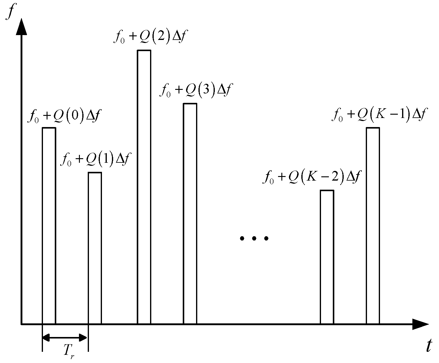
where t ^ and t k denote the fast time and slow time, respectively, t = t ^ + t k , t k = k T r ; Tr denotes the pulse repetition interval (PRI), uMSK,k is the baseband MSK modulated signal; k is the index of the pulse signal to be employed; fQ(k) = f0 + Q(k)∆f, Q(k) is the kth random frequency-modulation code Q(k)∈[0, 1, ⋯, G − 1]; K is the pulses number. Figure 2 shows a schematic diagram of the carrier frequency agile pattern.
After system synchronization, the reference signal received by the reference antenna can be expressed as
s r e f t = A r u M S K , k t ^ τ 0 e j 2 π f Q k t e j 2 π f Q k τ 0 + n r e f t
where Ar is the complex amplitude of the reference signal and τ0 is the propagation delay from the illuminator directly to the receiver, which is known a priori for the dedicated illuminator and receiver. nref(t) is the zero-mean additive white Gaussian (AWGN) noise in the reference channel.
Similarly, for a point target, the target echo signal received by the surveillance antenna can be given as
s s u r t = A s u M S K , k t ^ τ s e j 2 π f Q k t e j 2 π f Q k 2 R 0 V t c + n s u r t
where As is the complex amplitude of the target echo signal; τs = 2(R0Vt)/c is the time delay of the target echo signal, R0 and V represent the initial range and radial velocity of the target respectively; c is the speed of light. It should be noted that τs is changing at each sampling point due to the movement of the target. Nonetheless, its influence on the complex envelope is negligible when VT < c/(2B) is satisfied, T is the coherent processing interval (CPI), and B is the pulse signal bandwidth. nsur(t) is the AWGN in the surveillance antenna.
Normally, to lower the sampling rate and the system complexity, the radio frequency signal is down-converted to the baseband for signal processing. As for the FA signal, the frequency agile bandwidth is wider than the actual signal bandwidth of a single pulse, which results in a higher sampling rate of the system. Thus, it is unsuitable to down-covert the FA signal to the baseband directly. To address this issue, a channelized data collecting system based on a polyphase filter is employed, which is achieved by dividing the broadband signal into several sub-bands uniformly [42]. In particular, the frequency agile pattern can be obtained via synchronization and spectrum demodulation in the reference channel. Then, the broadband received signals are down-converted and sampled in each subband for signal processing. After the down-convert operation, the reference signal can be represented as the following.
s r e f t = A r u M S K , k t ^ + n r e f t
Similarly, after the channelized receiving and down-convert operation, the target echo signal is given by the following.
s s u r t = A s u M S K , k t ^ τ s e j 4 π f Q k R 0 V t c + n s u r t

2.2. Problem Analysis

From (5), it can be seen that the following four phase terms exist in the target echo signal.
φ 1 = j 4 π f 0 R 0 / c φ 2 = j 4 π Q k Δ f R 0 / c φ 3 = j 4 π f 0 V t / c φ 4 = j 4 π Q k Δ f V t / c
The first term, φ1, and the second term, φ2, are range-phase terms, where φ1 is a constant phase term couples with the fixed carrier frequency f0; φ2 is the hopping range phase term induced by agile carrier frequency, which is related to the initial range R0. The third term, φ3, and the fourth term, φ4, are Doppler phase terms, where φ3 is the Doppler phase term couples with the fixed carrier frequency f0, from which the velocity information of the target can be extracted; φ4 is the additional phase term, which is coupled with agile carrier frequency and the target velocity.
In traditional narrowband signal processing, the carrier frequency of the transmitted signal is fixed, that is, the range and Doppler phase are constant, and there are no hopping phase terms in the signal phase. Therefore, an FFT operation can be used to estimate the target velocity along a slow time dimension after matched filtering in the range dimension, then the energy can be coherently accumulated. However, in an FA signal, the range phase and Doppler shift are ‘hopped’ with the pulse index (carrier frequency hopping pattern), which destroys the consistency between pulses. As a result, the conventional coherent integration method through the FFT is no longer applicable, and additional processes should be conducted to compensate for the range phase and Doppler phase terms.

3. Proposed FAPBR Coherent Integration Scheme

In this section, the detailed processes of the proposed coherent integration scheme are introduced, which consist of three main steps: (1) Doppler migration correction via the phase quadratic difference; (2) HRRP generation by reordering the pulses sequence (carrier frequency hopping pattern); (3) range ambiguity effect elimination via the S-RAD method.

3.1. Doppler Migration Correction

In the radar field, the target Doppler frequency is a function of the radial speed of the moving target and carrier frequency, and thus the Doppler frequency of a moving target is constant in single-frequency radar. However, in the FAPBR system, the Doppler frequency of a moving target varies due to the randomly stepped carrier frequency. When the Doppler frequency difference exceeds the system’s Doppler resolution, which depends on the integration time, the target echo will exhibit a Doppler broadening effect. Further, both range-phase and Doppler-phase terms change with the carrier frequency, making the range and Doppler parameters coupled in an FA signal compared to a stepped-frequency signal [25]. Therefore, the direct extraction of target Doppler information and, thus, the obtaining of coherent integration via the conventional RDP, is invalid. The Doppler parameters should be estimated separately by eliminating the influence of the range phase term first. Correspondingly, a velocity estimation algorithm based on the phase quadratic difference is proposed, which eliminates the range phase terms by conjugate multiplication and then estimates the velocity through one-dimensional velocity searching.
Specifically, the received signals are divided into K equivalent pulses with duration Tr. The intra-pulse is called fast time t ^ , and the inter-pulse is called slow time t k . After the pulse compression, the surveillance signal can be expressed as
s s u r τ , t k = ω ( τ ) e j 4 π f Q k R 0 V t k c + n p τ , t k
where np is the noise term in τtk domain after the pulse compression and ω ( τ ) is the pulse compression result, expressed as the following.
ω ( τ ) = 0 T r A r * u M S K , k * t ^ τ A s u M S K , k t ^ τ s d t ^
Then, a one-dimensional velocity search on the range cell at τ = τs is performed. Assuming that the current velocity search value is Vsearch, then the velocity after compensation can be expressed as ∆V = VVsearch. Thus, the signal of the current range unit can be expressed as the following (for convenience, the phase part is only considered).
p τ s t k = e j 4 π f Q k R 0 Δ V t k c
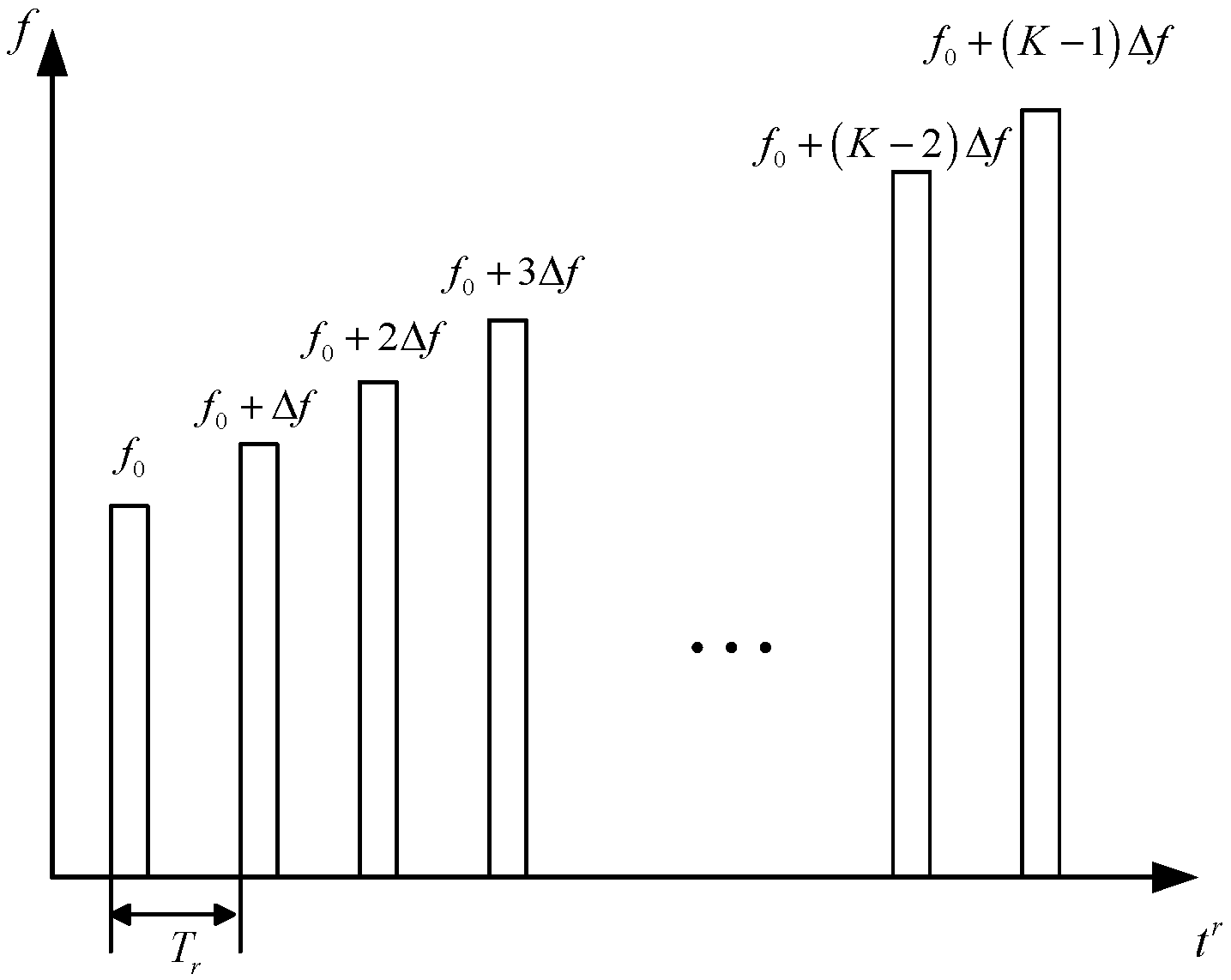
By Equation (9), it can be concluded that the signal phase contains two variables: the range phase term and the Doppler phase term. To separately estimate the velocity, conjugate multiplication is utilized to achieve a Doppler phase difference and eliminate the range phase term. Significantly, before the phase difference, the pulses need to be reordered to obtain the continuity of the carrier frequency. The order of carrier frequency after reordering is ascending and the rearranged signal can be given as the following.
p τ s t k r = e j 4 π f k R 0 Δ V t k r c
After the pulse reordering, the signal in (10) can be regarded as a special type of stepped-frequency signal. The FA pattern after signal reordering is shown in Figure 3. In (10), t k r = Q−1(k)Tr is the time series after pulse reordering, Q−1(k) is the inverse function of Q(k) and fk = f0 + kf is the carrier frequency of the k-th pulse after reordering.
Then, the phase difference result of k-th and the (k + 1)-th pulse can be represented as the following.
J τ s k = p τ s t k r p τ s * t k + 1 r   = e j 4 π f k Δ V t k + 1 r t k r c e j 4 π Δ f Δ V t k + 1 r c e j 4 π Δ f R 0 c
Similarly, the phase difference result of the (k + 1)-th and the (k + 2)-th pulse after reordering can be represented as the following.
J τ s k + 1 = p τ s t k + 1 r p τ s * t k + 2 r   = e j 4 π f k + 1 Δ V t k + 2 r t k + 1 r c e j 4 π Δ f Δ V t k + 2 r c e j 4 π Δ f R 0 c
Through Equations (11) and (12), it can be seen that the range phase term is decoupled from the agile carrier frequency fk, and is solely related to the ∆f, which means the range phase term is a constant. Therefore, the second phase difference is performed to further eliminate the remaining range phase term, written as
J τ s k = J τ s k J τ s * k + 1   = e j 4 π f k 2 t k + 1 r t k r t k + 2 r c Δ V e j 4 π Δ f t k + 2 r t k + 1 r c Δ V   = e j 4 π f k + 1 Δ t k + 1 r c Δ V e j 4 π f k Δ t k r c Δ V
where ∆ t k r = t k + 1 r t k r is the interval of the time series after reordering.
From Equation (13), the influence of the hopping range phase exp[−j4π(f0 + Q(k)∆f)R0/c] has been eliminated via phase quadratic difference. Meanwhile, due to the fact that the interval of the time series after reordering is no longer fixed, the Doppler phase term coupled with Δ t k r is preserved during the conjugate multiplication. Then, a phase difference operator is constructed, which can be expressed as
ψ Δ V = k = 0 K 2 a r g J τ s k ± π   = k = 0 K 2 4 π f k + 1 Δ t k + 1 r c f k Δ t k r c Δ V ± π
where arg[]±π denotes the operator of extracting the angle corresponding to the signal phase in the range of ±π.
It can be concluded that when ∆V = 0, all the velocity phase terms will cancel each other out, causing the angle ψ(∆V) to equal 0. Correspondingly, the phase difference reaches the minimum value. Moreover, since the phase quadratic difference method is a one-dimensional velocity search algorithm, it requires minimal computational effort, making the real-time motion compensation of an FA signal possible.
Figure 4 shows the target velocity estimation result of the proposed phase quadratic difference method. The signal simulation parameters are shown in Table 1 of Section 4.1. These results are based on the assumption that the target speed is 52 m/s and pulse compression has been completed. It can be seen from Figure 4 that there is a global optimal point in the estimated speed of the target. When the search speed matches the true target speed, the phase difference value is the smallest, which is completely consistent with the theoretical analysis in (14).

3.2. HRRP Generation

After the above processing, we can accurately estimate the velocity of the target so that the Doppler phase terms can be eliminated through motion compensation in the target signal. Thus, the target echo in (10) can be written as follows.
p τ s , V k = e j 4 π f 0 + k Δ f R 0 c
From Equation (15), the FA signal after pulse rearrangement and motion compensation can be regarded as the stepped-frequency signal. Therefore, by performing a discrete Fourier transform (DFT) on (15) we can obtain the target HRRP as
p τ s , V R s = k = 0 K 1 e j 4 π f 0 + k Δ f R 0 c e j 2 π f 0 + k Δ f 2 R s c
where Rs is the test range information.
Since the signal carrier frequency presents a uniform step after pulse rearrangement, an IFFT can be used to quickly implement (16). Note that, in a real FAPBR system, there will be multiple pulses transmitted through the same frequency channel in a CPI. Consequently, we could first sum the pulse signals with the same carrier frequency, and then generate the HRRP along different frequency pulses.

3.3. Sliding Range Ambiguity Decoupling

In radar systems, the design of PRIs should be based on the maximum detection range of the system, and there should be no distance ambiguity problem. However, for the sake of obtaining excellent ECCM performance, the FA signals always have the characteristics of rapidly switching carrier frequencies in each pulse, which requires the design of a shorter PRI, i.e., HPRF. While HPRF can enhance the signal anti-jamming capability, it can also lead to significant detection range and PRI coupling issues [43]. The coupling issue is also called range ambiguity in traditional active radar systems. The difference is that there are no ambiguous peaks, in this paper, when the agile navigation signal is the transmitted source. The reason is that, in an agile navigation signal, the modulation information in each pulse is different, thereby preventing the occurrence of ambiguous peaks during pulse compression between different pulses. Therefore, the range ambiguity effect implies that the targets will disappear in the case that the target echo delay exceeds the PRI length.
In PBR detection, the target motion parameters can be calculated by performing a sliding correlation between the time-delayed reference signal and surveillance signal during a CPI. Thus, there is no coupling problem between the PRI and the target detection range. Based on this, we proposed a sliding range ambiguity decoupling (S-RAD) method; the detailed procedure of S-RAD is as follows.
Firstly, for a pulse signal with a PRI of Tr, the ambiguous range is τua = cTr/2, i.e., the system’s maximum detection range is cTr/2. Based on this consideration, we can assume the real range delay τs to be τs = τs0 + muaτua, τs0 denotes the unambiguous velocity; mua is the fold factor. Then, to eliminate the range limitation caused by HPRF, we define τua as the sliding step. The surveillance signal at the m-th sliding range cell can be written as ssur(tua), m = 0, 1, ⋯, M. Correspondingly, after the sliding operation, the system’s unambiguous range will extend to M·cTr/2. Subsequently, as described in Section 3.1, the received signals are divided into K pulses with the PRI of Tr. The sliding surveillance signal matrix with fast and slow time forms can, therefore, be expressed as follows.
S s u r , τ u a = s s u r t ^ + m τ u a , t 0 ; s s u r t ^ + m τ u a , t 1 ; ; s s u r t ^ + m τ u a , t K 1 T
Similarly, the reference signal matrix with fast and slow time forms is expressed as follows.
S r e f = s r e f t ^ , t 0 ; s r e f t ^ , t 1 ; ; s r e f t ^ , t K 1 T
Based on (17) and (18), the pulse compression result of (7) can be re-calculated via the following.
s s u r , p c τ , m τ u a , t k = 0 T r A r * u M S K , k * t ^ τ A s u M S K , k t ^ + m τ u a τ s 0 m u a τ u a d t ^ e j 4 π f Q k R 0 V t k c
By (19), we can determine that the estimated target range is τ + ua, which corresponds to the unambiguous distance of the target.
The purpose of the sliding operation is to align the envelope of the target echo with the reference signal. When the envelope of the target echo matches the reference signal exactly during the sliding, the carrier frequency of the target echo signal and reference signal both strictly correspond to the frequency agile pattern. Therefore, the sliding operation can eliminate the range ambiguity without affecting the target’s phase information. The detailed procedure of the proposed S-RAD is given in Figure 5. It can be seen that, as the sliding interval shifts, the influence of the ambiguous range effect is compensated for, and the target’s echo energy is focused within the corresponding range grid.
To sum up, the proposed range ambiguity decoupling method makes full use of the characteristics of passive bistatic radar and the FA signal. Through the method of the S-RAD, the coupling effect between the detection range and PRI is eliminated, thereby the maximum detection range limited by the HPRF can be ignored.

4. Simulation and Performance Analysis

To verify the effectiveness of the proposed coherent integration methods for FAPBR, several numerical experiments are given in this section. The simulation parameters are set based on the JTIDS signal [44]. It is assumed that the baseband of the FA signal is the MSK-modulated pulse signal. The specific parameters are shown in Table 1, and each frequency-modulation code Q(k) (k = 0, 1, ⋯, K − 1) independently follows a uniform distribution over [f0, f0 + ∆f, ⋯, f0 + (G − 1)∆f], and G is set to 50. Then, we have the coarse range resolution c/2B = 30 m, and finer range resolution c/2Gf = 0.6 m.

4.1. Coherent Integration for Multiple Target

In the simulation scenario, three targets moving at a constant velocity are synthesized in the target echo signal. The detailed parameters of the three targets are shown in Table 2. Obviously, targets 1, 2, and 3 have different parameters (speed and range), and thus, different Doppler broadening effects are presented. Further, targets 2 and 3 are considered ambiguous targets due to the unambiguous range being cTr/2 = 1950 m.
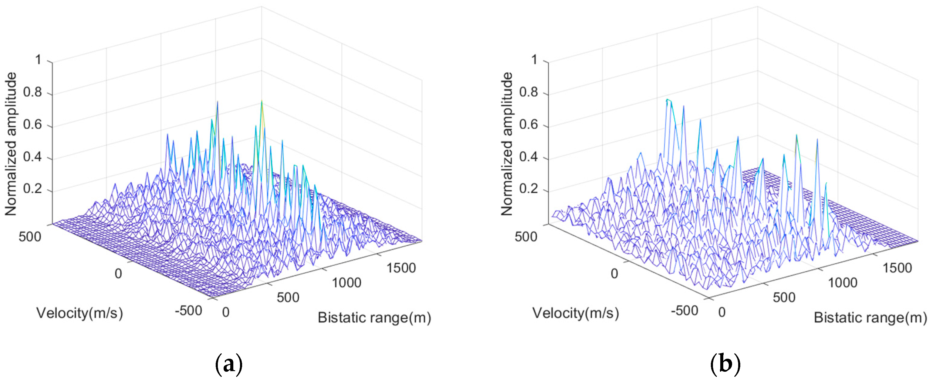
In order to compare the effectiveness and performance of the proposed method, seven existing methods are also carried out for the FA signal. Figure 6a,b shows the results of the traditional coherent integration methods of RDP and MTD, respectively. It is observed that the integration results of these two methods are discretely distributed in the range–velocity (RV) map and cannot form effective peaks. The reason is that the agile carrier frequency makes signal range and Doppler phase fluctuations, which in turn causes the target echo to be non-coherent. Figure 6c gives the result of the hybrid integration (HI) method, in which target 1 can be distinguished effectively. However, the other two targets cannot be detected since their range exceeds the PRI length, i.e., the range ambiguity effect occurs. Moreover, since Doppler filtering is implemented between non-uniformly distributed pulses of the same frequency, the signal is undersampled in the slow time dimension, leading to spectral aliasing and resulting in severe sidelobes. Figure 6d describes the result of JZP. In this method, the Doppler phase is compensated for via a velocity searching operation, thereby the JZP is also denoted as JZP-VS. As is apparent, target 1 is focused well, and the desired integral gain can be obtained. However, similar to the previous case, only target 1 can be detected effectively due to the limitation of HPRF.
Since the HI and JZP-VS methods can effectively focus the target within one PRI, the proposed S-RAD method is introduced into these two methods to better compare with the proposed method, denoted as the HI&S-RAD and JZP-VS&S-RAD methods. The results of these methods are shown in Figure 7. Specifically, Figure 7a shows the integration results of the HI&S-RAD method. From this, we can observe that all three targets can be detected, but the target SNR is degraded due to the non-coherent integration of the pulse signal with different carrier frequencies. In particular, the weak target 3 is almost submerged in noise after integration. Figure 7b describes the integration result of the JZP-VS&S-RAD method, in which all three targets can be observed obviously. However, this method requires motion compensation and the Doppler filtering of all range units after every velocity value search, leading to a substantial computational burden (described in Section 4.2).
The coherent integration results of the method presented in this paper are shown in Figure 8. Specifically, the phase quadratic difference is first performed to estimate and compensate for the target’s Doppler phase after pulse compression. The estimated target velocity results are represented in Figure 8a–c. As desired, the target speed estimated by the proposed method is consistent with the true speed. Further, when the search value matches the truth velocity of the target, the phase difference value appears as a global minimum point.
Figure 9 shows the HRRP results of the three targets. It can be seen that all targets are focused well and formed unique peaks. Meanwhile, it can be seen that the proposed method can obtain comparable performance with the modified JZP-VS&S-RAD method. Further, the proposed method requires a lower computational cost compared with the JZP-VS&S-RAD method (described in Section 4.2). In particular, from Figure 9 we can observe that the three targets are located at (1050 m, 15.88 m), (18,540 m, 14.71 m), and (22,560 m, 17.06 m). According to the logical relationship, the bistatic ranges represented by those values are 1065.88 m, 18,554.71 m, and 22,577.06 m, respectively, which are equal to the real range values.

4.2. Performance Analysis

In order to verify the superiority of the proposed method in detection performance, several methods are conducted with different input SNRs for comparison. Since the RDP, MTD, HI, and JZP-VS methods cannot detect targets effectively, we only give the detection performance analysis of modified the HI&S-RAD and JZP-VS&S-RAD methods. The input SNRs vary from −25 dB to 0 dB. The integration performance with different SNRs is calculated through 100 repeats of the Monte Carlo trials. The signal simulation parameters are the same as in Table 1. Figure 10 shows the detection performance of the above-mentioned methods in different input SNRs. It is clear to note that the detection performance of the proposed method precedes the HI&S-RAD method and obtains comparable performance with respect to the JZP-VS&S-RAD method. However, the computational complexity of the JZP-VS&S-RAD method is larger than that of the proposed method. Additionally, the proposed method can overcome the range ambiguity effect.
Further, the computational complexity of the proposed method is analyzed in terms of complex multiplications (CMs). In particular, the CMs of the modified HI&S-RAD and JZP-VS&S-RAD methods are also given for comparison. Assuming that the number of available frequencies is G, the pulse number is K, the number of searching velocity cells is Nv, and the number of range units sliding is Ns. In terms of the proposed method, the phase quadratic difference requires (2K − 3)NsNv CMs first, then the Doppler compensation costs 2GNs CMs. After that, the HRR generation and coherent integration need NsGlog2(G)/2 CMs. The detailed computational complexities of the above-mentioned methods are outlined in Table 3. Assuming that G = 50, Nv = 1000, and Ns = 1000, the relationship between the computational complexity and pulse number for the different methods is shown in Figure 11. It can be seen that the computational complexity of the proposed method is significantly reduced compared with that of the JZP-VS&S-RAD method under the same signal length. Further, although the computational complexity of the proposed method is greater than that of the HI&S-RAD method, its coherent accumulation performance significantly outperforms that of the HI&S-RAD method.

5. Conclusions

In this paper, which aims at utilizing the FA signal as the available illuminator, the characteristics of FAPBR are introduced and analyzed in detail. The target range and Doppler phase are hopping due to the agile carrier frequency, thereby causing the target signal to be incoherent. An innovative FAPBR coherent integration scheme is presented to suppress the phase fluctuation and generate an HRRP. Compared with the conventional methods, the proposed methods not only have a small calculation amount but also can exhibit the desired coherent integration performance for multiple moving targets. Meanwhile, we introduce the concept of the sliding operation to overcome the range ambiguity effect, and, through this, the maximum detection range limited by HPRF can be exceeded. Simulation experiments are conducted to verify the fundamental mechanism and the specific procedures of the proposed methods.

Author Contributions

Conceptualization, L.Z.; methodology, N.L. and J.T.; validation, J.T.; software, X.P. and Z.Z.; investigation, Y.C.; writing—review and editing, L.Z.; visualization, J.H. All authors have read and agreed to the published version of the manuscript.

Funding

This research received no external funding.

Data Availability Statement

Due to the nature of this research, the participants of this study did not agree for their data to be shared publicly, so the supporting data are not available.

Acknowledgments

The authors would like to thank the support of the laboratory and university.

Conflicts of Interest

The authors declare no conflicts of interest.

References

  1. Malanowski, M. Signal Processing for Passive Bistatic Radar; Artech House: London, UK, 2019. [Google Scholar]
  2. Blázquez-García, R.; Cristallini, D.; Ummenhofer, M.; Seidel, V.; Heckenbach, J.; O’Hagan, D. Capabilities and challenges of passive radar systems based on broadband low-Earth orbit communication satellites. IET Radar Sonar Navig. 2024, 18, 78–92. [Google Scholar] [CrossRef]
  3. Kuschel, H.; Cristallini, D.; Olsen, K.E. Tutorial: Passive radar tutorial. IEEE Aerosp. Electron. Syst. Mag. 2019, 34, 2–19. [Google Scholar] [CrossRef]
  4. Abratkiewicz, K.; Księżyk, A.; Płotka, M.; Samczyński, P.; Wszołek, J.; Zieliński, T.P. SSB-Based Signal Processing for Passive Radar Using a 5G Network. IEEE J. Sel. Top. Appl. Earth Obs. Remote Sens. 2023, 16, 3469–3484. [Google Scholar] [CrossRef]
  5. Almodóvar-Hernández, A.; Mata-Moya, D.; Jarabo-Amores, M.-P.; Rey-Maestre, N.; Benito-Ortiz, M. Motion Compensation for Long Integration Times and DoA Processing in Passive Radars. Remote Sens. 2023, 15, 1031. [Google Scholar] [CrossRef]
  6. Griffiths, H.D.; Baker, C.J. An Introduction to Passive Radar; Artech House: London, UK, 2022. [Google Scholar]
  7. Ma, J.; Li, H.; Gan, L. Order-Statistic Based Target Detection with Compressive Measurements in Single-Frequency Multistatic Passive Radar. Signal Process. 2023, 203, 108785. [Google Scholar] [CrossRef]
  8. Blasone, G.P.; Colone, F.; Lombardo, P. Forward-Looking Passive Radar with Non-Uniform Linear Array for automotive applications. IEEE Trans. Veh. Technol. 2023, 72, 11132–11146. [Google Scholar] [CrossRef]
  9. Zhang, C.; Shi, S.; Yan, S.; Gong, J. Moving Target Detection and Parameter Estimation Using BeiDou GEO Satellites-Based Passive Radar with Short-Time Integration. IEEE J. Sel. Top. Appl. Earth Obs. Remote Sens. 2023, 16, 3959–3972. [Google Scholar] [CrossRef]
  10. Wang, Y.; Bao, Q.; Wang, D.; Chen, Z. An experimental study of passive bistatic radar using uncooperative radar as a transmitter. IEEE Geosci. Remote Sens. Lett. 2015, 12, 1868–1872. [Google Scholar] [CrossRef]
  11. Howland, P.E.; Maksimiuk, D.; Reitsma, G. FM radio based bistatic radar. IEE Proc. Radar Sonar Navig. 2005, 152, 107–115. [Google Scholar] [CrossRef]
  12. Lü, M.; Yi, J.; Wan, X.; Zhan, W. Cochannel interference in DTMB-based passive radar. IEEE Trans. Aerosp. Electron. Syst. 2018, 55, 2138–2149. [Google Scholar] [CrossRef]
  13. Zuo, L.; Wang, J.; Zhao, T.; Cheng, Z. A Joint Low-Rank and Sparse Method for Reference Signal Purification in DTMB-Based Passive Bistatic Radar. Sensors 2021, 21, 3607. [Google Scholar] [CrossRef] [PubMed]
  14. Geng, Z.; Xu, R.; Deng, H. LTE-based multistatic passive radar system for UAV detection. IET Radar Sonar Navig. 2020, 14, 1088–1097. [Google Scholar] [CrossRef]
  15. Gui, L.; Yuan, W.; Xiao, F. CSI-based passive intrusion detection bound estimation in indoor NLoS scenario. Fundam. Res. 2023, 3, 988–996. [Google Scholar] [CrossRef]
  16. Ma, H.; Antoniou, M.; Stove, A.G.; Winkel, J.; Cherniakov, M. Maritime moving target localization using passive GNSS-based multistatic radar. IEEE Trans. Geosci. Remote Sens. 2018, 56, 4808–4819. [Google Scholar] [CrossRef]
  17. Wang, B.; Cha, H.; Zhou, Z.; Tian, B. Clutter cancellation and long time integration for GNSS-based passive bistatic radar. Remote Sens. 2021, 13, 701. [Google Scholar] [CrossRef]
  18. Huang, C.; Li, Z.; An, H.; Sun, Z.; Wu, J.; Yang, J. Passive multistatic radar imaging of vessel target using GNSS satellites of opportunity. IEEE Trans. Geosci. Remote Sens. 2022, 60, 1–16. [Google Scholar] [CrossRef]
  19. Wang, H.; Kuang, J.; Wang, Z.; Xu, H. Transmission performance evaluation of JTIDS. In Proceedings of the MILCOM 2005–2005 IEEE Military Communications Conference, Atlantic City, NJ, USA, 17–20 October 2005; pp. 2264–2268. [Google Scholar]
  20. Bai, L.; Wang, J.; Chen, X. Ambiguity function analysis and side peaks suppression of Link16 signal based passive radar. J. Syst. Eng. Electron. 2023, 34, 1526–1536. [Google Scholar] [CrossRef]
  21. Liu, L.; Fu, Y.; Li, Q.; Lu, Y.; Cao, Z.; Chen, Y. Anti-jamming Research of UAV Communication Based on Link-16 Datalink. In Proceedings of the 2023 6th International Conference on Computer Network, Electronic and Automation (ICCNEA), Xi’an, China, 22–24 September 2023; pp. 157–161. [Google Scholar]
  22. Huang, T.; Liu, Y.; Xu, X.; Eldar, Y.C.; Wang, X. Analysis of frequency agile radar via compressed sensing. IEEE Trans. Signal Process. 2018, 66, 6228–6240. [Google Scholar] [CrossRef]
  23. Axelsson, S.R. Analysis of random step frequency radar and comparison with experiments. IEEE Trans. Geosci. Remote Sens. 2007, 45, 890–904. [Google Scholar] [CrossRef]
  24. Zuo, L.; Wang, J.; Wang, J.; Chen, G. UAV detection via long-time coherent integration for passive bistatic radar. Digit. Signal Process. 2021, 112, 102997. [Google Scholar] [CrossRef]
  25. Huang, C.; Li, Z.; Lou, M.; Qiu, X.; An, H.; Wu, J.; Yang, J.; Huang, W. BeiDou-based passive radar vessel target detection: Method and experiment via long-time optimized integration. Remote Sens. 2021, 13, 3933. [Google Scholar] [CrossRef]
  26. Wang, H.; Huang, W.; Jiang, Y.; Ba, T. Moving target coherent integration method for non-coherent short pulse radar. IET Radar Sonar Navig. 2019, 13, 953–960. [Google Scholar] [CrossRef]
  27. Jędrzejewski, K.; Malanowski, M.; Kulpa, K.; Pożoga, M. Experimental verification of passive radar space object detection with a single low-frequency array radio telescope. IET Radar Sonar Navig. 2024, 18, 68–77. [Google Scholar] [CrossRef]
  28. Colone, F.; Lombardo, P. Non-coherent adaptive detection in passive radar exploiting polarimetric and frequency diversity. IET Radar Sonar Navig. 2016, 10, 15–23. [Google Scholar] [CrossRef]
  29. Martelli, T.; Colone, F.; Tilli, E.; Di Lallo, A. Multi-frequency target detection techniques for DVB-T based passive radar sensors. Sensors 2016, 16, 1594. [Google Scholar] [CrossRef] [PubMed]
  30. Huang, P.; Dong, S.; Liu, X.; Jiang, X.; Liao, G.; Xu, H.; Sun, S. A coherent integration method for moving target detection using frequency agile radar. IEEE Geosci. Remote Sens. Lett. 2018, 16, 206–210. [Google Scholar] [CrossRef]
  31. Olsen, K.E.; Christiansen, J.M. Multiband passive bistatic radar coherent range and Doppler-walk compensation. In Proceedings of the 2015 IEEE Radar Conference (RadarCon), Arlington, VA, USA, 10–15 May 2015; pp. 0123–0126. [Google Scholar]
  32. Lin, C.; Tian, R.; Bao, Q.; Chen, Z. Coherent integration method of frequency agile radar for target detection. In Proceedings of the 2017 Sixth Asia-Pacific Conference on Antennas and Propagation (APCAP), Xi’an, China, 16–19 October 2017; pp. 1–3. [Google Scholar]
  33. Chen, G.; Wang, J.; Zuo, L.; Zhao, D. Long-Time Coherent Integration for Frequency Hopping Pulse Signal via Phase Compensation. IEEE Access 2020, 8, 30458–30466. [Google Scholar] [CrossRef]
  34. Liu, L.; Zhang, Y.; Cai, C.; Liu, X. An improved algorithm for compatibility of pulse-to-pulse frequency agility and MTD. Comput. Simul. 2011, 28, 5–8. [Google Scholar]
  35. Quan, Y.; Li, Y.; Wu, Y.; Ran, L.; Xing, M.; Liu, M. Moving target detection for frequency agility radar by sparse reconstruction. Rev. Sci. Instrum. 2016, 87, 094703. [Google Scholar] [CrossRef]
  36. Li, Y.; Huang, T.; Xu, X.; Liu, Y.; Wang, L.; Eldar, Y.C. Phase transitions in frequency agile radar using compressed sensing. IEEE Trans. Signal Process. 2021, 69, 4801–4818. [Google Scholar] [CrossRef]
  37. Lellouch, G.; Pribic, R.; van Genderen, P. Merging frequency agile ofdm waveforms and compressive sensing into a novel radar concept. In Proceedings of the 2009 European Radar Conference (EuRAD), Rome, Italy, 30 September–2 October 2009; pp. 137–140. [Google Scholar]
  38. Liao, Z.; Lu, D.; Hu, J.; Zhang, J. Computationally efficient range profile synthesis method based on zero-padding inverse discrete Fourier transform for random stepped frequency radar. J. Appl. Remote Sens. 2019, 13, 016505. [Google Scholar] [CrossRef]
  39. Liu, S.; Cao, Y.; Yeo, T.-S.; Wang, F.; Han, J. Range sidelobe suppression for randomized stepped-frequency chirp radar. IEEE Trans. Aerosp. Electron. Syst. 2021, 57, 3874–3885. [Google Scholar] [CrossRef]
  40. Malanowski, M. Detection and parameter estimation of manoeuvring targets with passive bistatic radar. IET Radar Sonar Navig. 2012, 6, 739–745. [Google Scholar] [CrossRef]
  41. Colone, F.; O’hagan, D.; Lombardo, P.; Baker, C. A multistage processing algorithm for disturbance removal and target detection in passive bistatic radar. IEEE Trans. Aerosp. Electron. Syst. 2009, 45, 698–722. [Google Scholar] [CrossRef]
  42. Harris, F.J.; Dick, C.; Rice, M. Digital receivers and transmitters using polyphase filter banks for wireless communications. IEEE Trans. Microw. Theory Tech. 2003, 51, 1395–1412. [Google Scholar] [CrossRef]
  43. Feixing, W.; Hongzhong, Z.; Jianxiong, Z.; Qiang, F. Range ambiguity resolution based on phase difference for high PRF stepped-frequency radar. Chin. J. Electron. 2008, 17, 751–755. [Google Scholar]
  44. Chen, J.; Zheng, X.; Zhang, C.; Xu, Z.; Li, A. The Capacity Analysis of the Orthogonal Frequency Hopping Stacked Nets in the Data Link. J. Phys. Conf. Ser. 2019, 1302, 022060. [Google Scholar] [CrossRef]
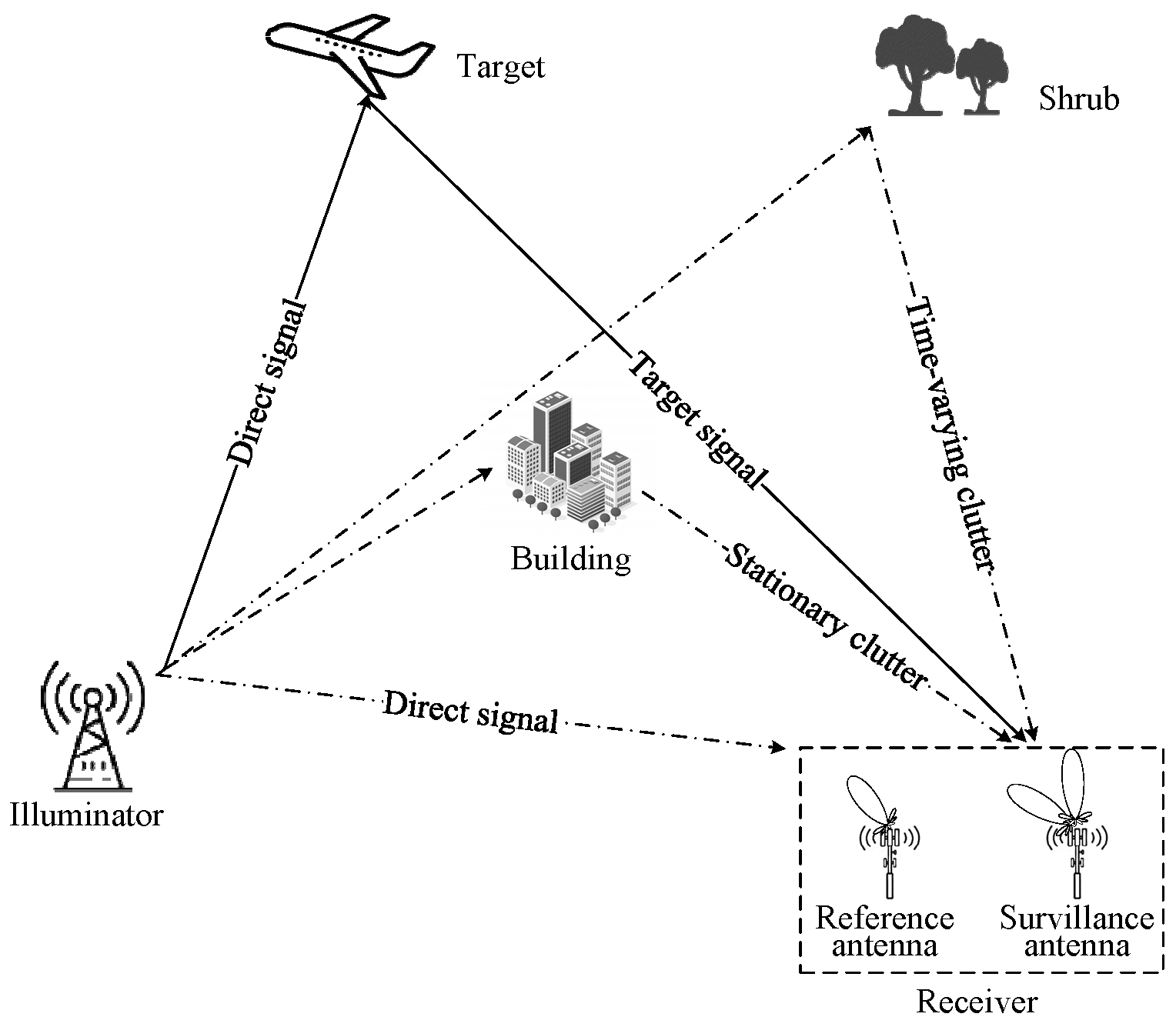
Figure 1. Passive bistatic radar geometry.
Remotesensing 16 01148 g001
Figure 2. Carrier frequency agile pattern.
Remotesensing 16 01148 g002
Figure 3. Carrier frequency agile pattern after reordering.
Remotesensing 16 01148 g003
Figure 4. Target velocity estimation result of the phase quadratic difference method.
Remotesensing 16 01148 g004
Figure 5. The procedure of S-RAD.
Remotesensing 16 01148 g005
Figure 6. Integration results of the existing methods. (a) RDP method; (b) MTD method; (c) hybrid integration method; (d) JZP-VS method.
Remotesensing 16 01148 g006aRemotesensing 16 01148 g006b
Figure 7. Integration results of existing methods. (a) HI&S-RAD method; (b) JZP-VS&S-RAD method.
Remotesensing 16 01148 g007
Figure 8. The velocity estimation result of three targets. (a) Target 1; (b) target 2; (c) target 3.
Remotesensing 16 01148 g008
Figure 9. HRRP result of the proposed method.
Remotesensing 16 01148 g009
Figure 10. Input–output SNR performance.
Remotesensing 16 01148 g010
Figure 11. The relationship between the computational complexity and pulse number of different methods.
Remotesensing 16 01148 g011
Table 1. Radar system parameters.
ParametersSymbolValues
Initial carrier frequency (MHz)f0875
Bandwidth (MHz)B5
Frequency step interval (MHz)f5
Available frequencies numberG50
Pulse duration time (μs)-6.4
Pulse repeat interval (μs)Tr13
CPI (ms)T50
Table 2. Simulation parameters of moving targets.
SignalSNR (dB)Bistatic Range (m)Velocity (m/s)
Target 1−101066−51
Target 2−1518,555129
Target 3−2022,57777
Table 3. Computational complexity of different methods.
MethodsCMs
HI&S-RADNsGKlog2(K)/2
JZP-VS&S-RADNsNvGlog2(G)/2 + 2KNsNv
Proposed methodNsGlog2(G)/2 + (2K − 3)NsNv + 2GNs
Disclaimer/Publisher’s Note: The statements, opinions and data contained in all publications are solely those of the individual author(s) and contributor(s) and not of MDPI and/or the editor(s). MDPI and/or the editor(s) disclaim responsibility for any injury to people or property resulting from any ideas, methods, instructions or products referred to in the content.