Article

Joint Implementation Method for Clutter Suppression and Coherent Maneuvering Target Detection Based on Sub-Aperture Processing with Airborne Bistatic Radar

School of Information and Communication Engineering, University of Electronic Science and Technology of China, Chengdu 611731, China
*
Author to whom correspondence should be addressed.
Remote Sens. 2024, 16(8), 1379; https://doi.org/10.3390/rs16081379
Submission received: 6 March 2024 / Revised: 31 March 2024 / Accepted: 11 April 2024 / Published: 13 April 2024

Abstract

:
An airborne bistatic radar working in downward-looking mode confronts two major challenges for low-altitude target detection. One is range cell migration (RCM) and Doppler migration (DM) resulting from the relative motion of the radar and target. The other is the non-stationarity characteristic of clutter due to the radar configuration. To solve these problems, this paper proposes a joint implementation method based on sub-aperture processing to achieve clutter suppression and coherent maneuvering target detection. Specifically, clutter Doppler compensation and sliding window processing are carried out to realize sub-aperture space–time processing, removing the clutter non-stationarity resulting from the bistatic geometric configuration. Thus, the output matrix of clutter suppression in the sub-aperture could be obtained. Then, the elements with the same phase of this matrix are superimposed and rearranged to achieve the reconstructed 2-D range-pluse echo matrix. Next, the aperture division with respect to slow time is conducted and the RCM correction based on modified location rotation transform (MLRT) and coherent integration (CI) are realized within each sub-aperture. Finally, the matched filtering process (MFP) is applied to compensate for the RCM/DM among different sub-apertures to coherently integrate the maneuvering target energy of all sub-apertures. The simulation and measured data processing results prove the validity of the proposed method.

1. Introduction

The airborne bistatic radar has anti-jamming, anti-stealth, and anti-destructiveness capabilities and has provoked a great deal of attention and research [1,2,3,4]. The airborne bistatic radar consists of a separate transmitter and receiver on two different platforms functioning at high speed, causing problems in relation to clutter non-stationarity/non-homogeneity and range cell migration (RCM)/Doppler migration (DM) when detecting a low-altitude maneuvering target, e.g., a missile, an unmanned aerial vehicle (UAV), etc. [5,6,7,8,9].
The non-stationarity characteristic denotes that the clutter in different range cells exhibits various spatial-time distributions, which is related to the geometric configuration of the transmitter and receiver [10]. This problem leads to serious performance degradation for the traditional adaptive processing method. The RCM and DM effects indicate that the maneuvering target energy distributes among different range/Doppler cells because of the relative motion (including the radial velocity and acceleration) between the target and radar, making the traditional coherent detection methods lose efficacy [11,12]. In order to overcome the above problems and improve the signal-to-clutter and noise rate (SCNR), effective clutter suppression and coherent detection are required.
As for the research into clutter suppression, single channel processing-based methods have been widely studied, involving Doppler filtering-based time-frequency analysis and feature decomposition-based methods. Doppler filtering-based methods consider the Doppler centroid shift of the moving target and realize static clutter suppression and the out-of-band detection of the clutter spectrum [13]. The typical time-frequency analysis methods involve the Wigner–Ville distribution (WVD) [14,15,16], WVD-Hough transform [17], LV’s distribution (LVD) [18,19,20], and fractional Fourier transform (FrFT) [21], which make use of the centroid and modulation frequency differences between the target and stationary clutter to complete clutter suppression and target detection. Moreover, the singular value decomposition (SVD) [22] and eigenvalue decomposition [23] belong to feature decomposition-based methods and they can eliminate the clutter energy point after echo reconstruction. The above single-channel clutter suppression methods have the advantages of simple hardware requirements and low operational complexity. However, it is difficult for airborne radars to detect a moving target within the mainlobe clutter using these methods because the clutter and target are simultaneously broadened.
Considering the limitations of the above single-channel methods in clutter suppression processing, methods using multi-channel data have been developed. Such typical methods include the displaced phase center antenna (DPCA) [24,25] and space–time adaptive processing (STAP) [26]. A DPCA is capable of suppressing stationary clutter while retaining moving target signals through pairwise cancellation processing of two-channel echo data. However, this method requires the platform velocity, channel spacing, and pulse repetition frequency (PRF) to meet strict requirements, i.e., the DPCA condition [25]. STAP makes full use of the spatial-temporal coupling characteristics of clutter signals to conduct joint space and time processing, which performs adaptive filtering on the echo data and maximizes the output SCNR [27]. Unfortunately, the problem of the computation of the optimal weight vector and accurate covariance matrix estimation for a space–time adaptive filter has always accompanied its development and constrained practical applications.
In terms of studies about coherent detection, the keystone transform (KT) was proposed and applied to correct the linear RCM via sinc interpolation along the slow-time dimension [11,28,29]. Then, the coherent integration (CI) of KT is completed by moving target detection (MTD). The modified location rotation transform (MLRT) was presented to rotate each data coordinate of the pulse compression echo and obtain the linear RCM correction results. The CI and detection is then achieved by slow-time Fourier transform [30]. Different from the above methods, Radon–Fourier transform (RFT) fulfills the CI by extracting the target energy trajectory via parameter searching [31]. However, these methods just aim at coherent detection under the condition that there is a relative velocity between the radar and target. When the relative acceleration motion appears, the coherent detection performance of these methods may degrade.
The technical studies on coherent detection for a maneuvering target with an acceleration focus on quadratic RCM and DM compensation. Generalized RFT (GRFT) was put forward on the basis of RFT via a parameter search in higher dimensions. In addition, the keystone transform-matched filtering process (KT-MFP) was investigated by KT correction and a joint search for the fold factor and acceleration. Such methods obtain the CI and detection results through a multi-dimensional parameter search, which requires a high computational complexity and struggles to cope with the clutter influence.
Overall, there are fewer studies that consider joint implementation clutter suppression and coherent detection, which is very important with regard to moving target detection within a strong clutter condition. The sub-coherent processing interval (CPI) STAP and keystone transform-Lv’s distribution (KT-LVD) are combined in [32]. But, it is hard to eliminate clutter non-stationary and achieve effective detection for the airborne bistatic radar.
For the sake of joint implementation clutter suppression and coherent maneuvering target detection, this paper considers combined space–time processing-based clutter suppression and RCM/DM elimination based on MLRT within a sub-aperture. There are three main processes in this method, including sub-aperture space–time processing by sliding window processing, range-Doppler echo matrix reconstruction, and RCM correction within the sub-aperture. Finally, the CI of all sub-apertures is realized and the SCNR can be improved significantly.
The contributions of this paper are shown in the following:
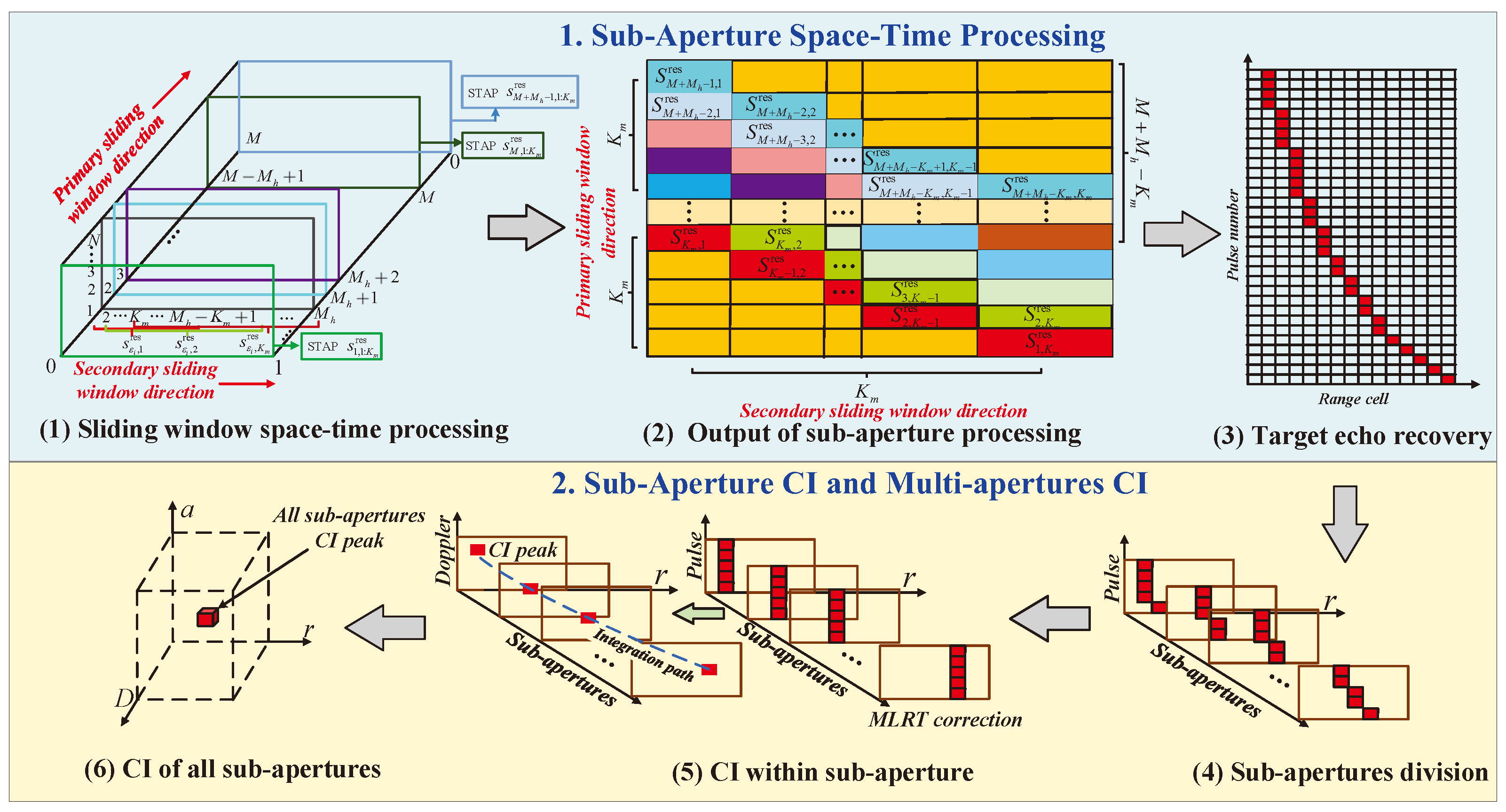
  • The joint implementation method based on sub-aperture processing to realize clutter suppression and coherent maneuvering target detection is given via sub-aperture processing;
  • The sub-aperture space–time processing is given to remove the clutter non-stationarity after clutter Doppler compensation and sliding window processing. Next, the echo is reconstructed in the range–slow-time domain to provide convenience for subsequent CI;
  • The slow-time aperture division is studied and the MLRT is applied to correct the RCM for each sub-aperture. Then, the matched filtering function is established to eliminate RCM/DM among different sub-apertures and coherent detection is realized by using all sub-apertures.
The remaining sections of this paper are arranged as follows: In Section 2, the mathematical model of the clutter and maneuvering target with an arbitrary configuration for an airborne bistatic radar is provided. Section 3 introduces the proposed sub-aperture processing method, including sub-aperture space–time processing, echo matrix reconstruction, and sub-aperture coherent detection. Section 4 gives the simulation and measured data processing results and analysis. Eventually, Section 5 gives a conclusion for the whole paper.

2. Materials and Methods
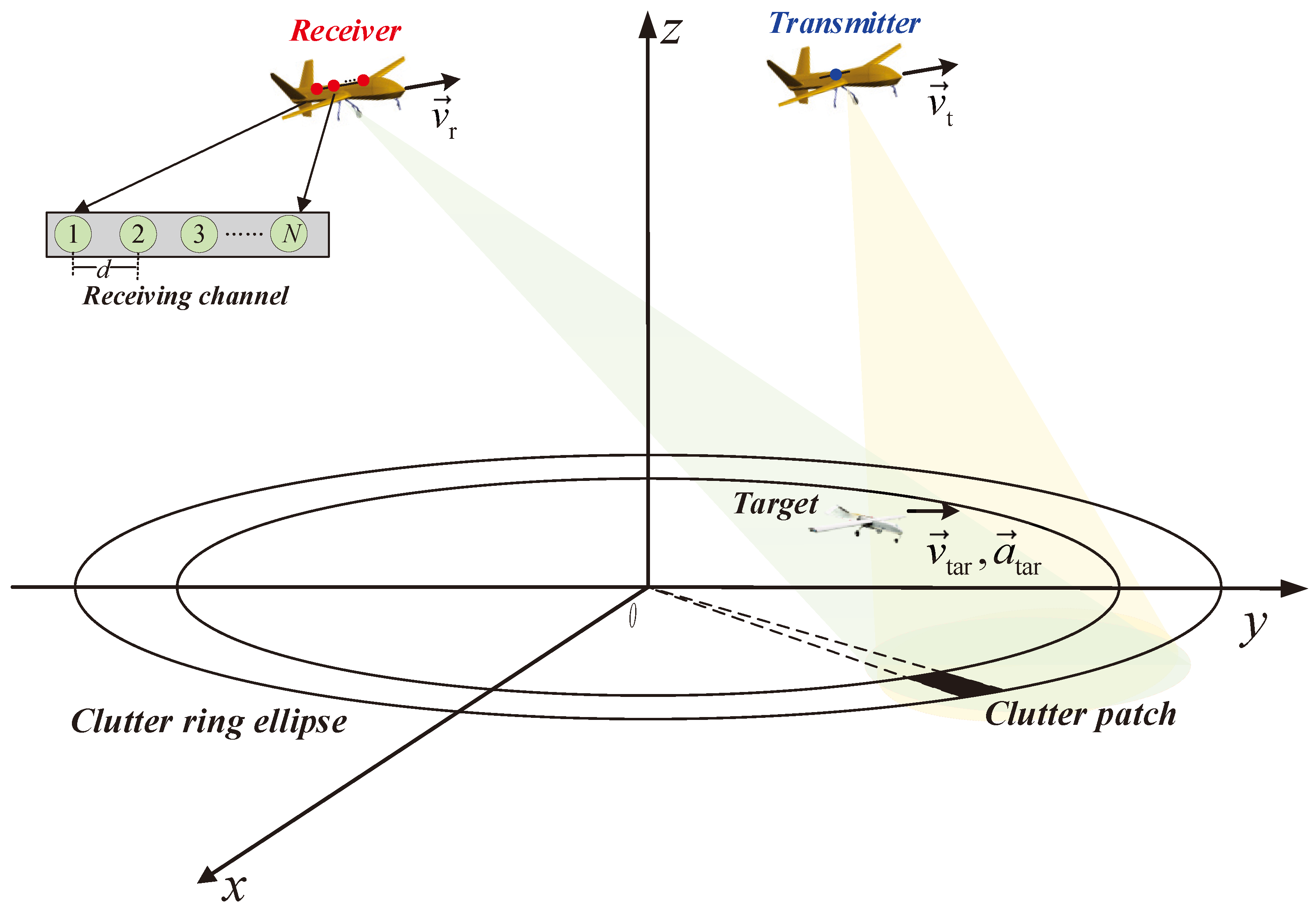
2.1. Signal Model

The 3-D geometric configuration of the maneuvering target and airborne bistatic radar system with downward-looking mode is considered in the Figure 1. In this figure, the transmitter is considered as an equivalent single-channel system and the receiver contains N receiving channels with the array element space d. Because of the flexible configuration of the transmitter and receiver in a real scenario, the moving direction and location of the transmitter and receiver are not fixed. Thus, the clutter ring consisting of clutter patches is usually presented as a non-standard ellipse. Suppose that the velocity and initial coordinate of the transmitter are represented as the vectors v T and R 0 , t , respectively. Similarly, the velocity and initial coordinate vectors of the receiver are given as v r and R 0 , r . The initial flight heights of the transmitter and receiver are defined as H t and H r . In addition, the maneuvering target flies at the initial height of H tar with initial slant range vector R 0 , tar , velocity vector v tar , and acceleration vector a tar .
According to Figure 1, the transient range vector R tar of the maneuvering target can be modeled as:
R tar = R 0 , tar + v tar t m + 1 2 a tar t m 2 ,
where t m = m P R I m = 1 , 2 , , M denotes the radar slow time. M and P R I indicate the total pulse number and pulse repetition interval, respectively.
Similarly, the instantaneous ranges of the transmitter and receiver can be separately written as
R t t m = R 0 , t + v t t m R r t m = R 0 , r + v r t m .
Assume that the signal range history is the same as the transient slant range. Therefore, the transient slant range R tr ( t m ) of the bistatic radar system, which is equivalent to that of the monostatic radar, can be approximated as
R tr ( t m ) = 1 2 R tar R t + R tar R r R 0 , tr + v eq , tr t m + 1 2 a eq , tr t m 2 ,
where
R 0 , tr = 1 2 R 0 , tar R 0 , t + R 0 , tar R 0 , r ,
v eq , tr = R 0 , r R 0 , tar v r v tar 2 R 0 , r R 0 , tar 2 + R 0 , t R 0 , tar v t v tar 2 R 0 , t R 0 , tar 2 ,
a eq , tr = v r v tar 2 2 ( sin 2 η r ) R 0 , r R 0 , tar 2 + v t v tar 2 2 ( sin 2 η t ) R 0 , t R 0 , tar 2 + a tar R 0 , r R 0 , tar R 0 , r R 0 , tar 2 + a tar R 0 , t R 0 , tar R 0 , t R 0 , tar 2 ,
| · | and · 2 separately indicate L1-norm and L2-norm. In addition, η t = cos 1 R 0 , tar R 0 , t v tar v t R 0 , tar R 0 , t 2 v tar v t 2 , η r = cos 1 R 0 , tar R 0 , r v tar v r R 0 , tar R 0 , r 2 v tar v r 2 . Considering the transmitter sends the linear frequency modulated (LFM) signal, i.e.,
s trans τ , t m = rect τ T p exp j π γ τ 2 exp j 2 π f c τ + t m ,
where rect ( z ) = 1 z 0.5 0 z > 0.5 . T p , γ and f c separately indicate the pulse duration, chirp rate, and carrier frequency. According to applying the pulse compression (PC) within the range frequency domain, the result can be given as
S tar f , t m = A 0 rect f B exp j 4 π f + f c R tr ( t m ) c ,
where A 0 represents the PC amplitude and it is a constant on that condition regardless of target fluctuation. f, c, and B denote the range frequency variable, light velocity, and bandwidth. We can obtain the slow-time-domain echo by the inverse Fourier transform (IFT), i.e.,
S tar ( τ , t m ) = A 1 sin c B τ 2 R tr ( t m ) c exp j 4 π R tr ( t m ) λ ,
where A 1 is the slow-time-domain echo amplitude. λ = c f c denotes the radar wavelength.
Let τ = 2 r / c and (9) could be recast as
S tar ( r , t m ) = A 1 sin c 2 B c r R tr ( t m ) exp j 4 π R tr ( t m ) λ .
Similarly, for the k-th clutter scattering patch, its transient slant range vector changes with t m ; then, we have
R ck ( t m ) = 1 2 R c k t m R t + R c k t m R r R 0 , c k t m + v eq , c k ( t m ) t m + 1 2 a eq , c k ( t m ) t m 2 ,
where
R 0 , c k t m = 1 2 R 0 , c k t m R 0 , t + R 0 , c k t m R 0 , r ,
v eq , c k ( t m ) = R 0 , r R 0 , c k t m v r 2 R 0 , r R 0 , c k t m 2 + R 0 , t R 0 , c k t m v t 2 R 0 , t R 0 , c k t m 2 ,
a eq , c k ( t m ) = R 0 , r R 0 , c k t m 2 2 v r 2 2 v r R 0 , r R 0 , c k t m 2 2 R 0 , r R 0 , c k t m 2 3 + R 0 , t R 0 , c k t m 2 2 v t 2 2 v t R 0 , t R 0 , c k t m 2 2 R 0 , t R 0 , c k t m 2 3 ,
R 0 , c k t m , v eq , c k ( t m ) and a eq , c k ( t m ) separately represent the equivalent initial range, velocity, and acceleration of the k-th clutter patch, which is time-varying due to the random motion of clutter [33].
Then, we can obtain the echo expression for the k-th clutter patch, namely,
S c k ( r , t m ) = A c k sin c 2 B c r R ck ( t m ) exp j 4 π R ck ( t m ) λ ,
where A c k is the amplitude of the clutter echo.
Suppose that the clutter echo could be deemed as the K clutter patches sum term, the clutter echo in the range–slow-time domain is modeled as
S c ( r , t m ) = k = 1 K A c k sin c 2 B c r R ck ( t m ) exp j 4 π R ck ( t m ) λ .
Considering the target, clutter, and noise components exist in the echo simultaneously, the total radar echo could be given as
S ( r , t m ) = S tar ( r , t m ) + S c ( r , t m ) + n ( r , t m ) = s ( f s , tar ) S tar ( r , t m ) + k = 1 K s ( f s , c k ( t m ) ) S c k ( r , t m ) + n ( r , t m ) ,
where
f s , tar = v r v tar R 0 , r R 0 , tar d 2 R 0 , r R 0 , tar 2 v r v tar 2 λ ,
f s , c k ( t m ) = v r R 0 , r R 0 , c k t m d 2 R 0 , r R 0 , c k t m 2 v r 2 λ ,
s ( f s , tar ) = 1 , e j 2 π f s , tar , , e j 2 π ( N 1 ) f s , tar T ,
s ( f s , c k ( t m ) ) = 1 , e j 2 π f s , c k ( t m ) , , e j 2 π ( N 1 ) f s , c k ( t m ) T ,
and d represents the array element space of the receiver, as shown in Figure 1. f s , tar and f s , c k ( t m ) denote the normalized spatial frequency of the target and clutter. s ( f s , tar ) and s ( f s , c k ( t m ) ) indicate the spatial steering vector. · T is the transpose operation. n ( r , t m ) represents additive white Gaussian noise signal. To suppress clutter and complete the maneuvering target CI result, a novel method based on sub-aperture processing is presented and introduced in the following section.

2.2. The Sub-Aperture Processing Method

First, sub-aperture sliding window processing is performed on the pulse dimension of the bistatic radar echo. For each set of sliding window data, spatiotemporal adaptive filtering is performed. Then, the filtered data with the same phase are superimposed to recover the target echo and clutter suppression is realized. Afterwards, for the recovered target signal, sub-aperture processing is performed and the MLRT algorithm is used for fast coherent accumulation within sub-apertures. Then, the accumulation results are subjected to inter-sub-aperture coherent stacking. The entire algorithm effectively highlights the maneuvering displayed in Figure 2 below.

Sub-Aperture Space–Time Processing

It is assumed that the clutter echoes of different channels remain highly coherent within a short dwell time. We designed the primary sliding window based on the correlation time of the clutter to ensure correlation within the sub-aperture. By selecting appropriate observation time intervals, it can alleviate the time decorrelation effect of clutter.
Assume the clutter correlation time of each channel calculated and estimated by the clutter power spectrum of the clutter data is expressed as t ^ 1 , t ^ 2 , , t ^ N , then the pulse number of the time window function is given by
M h = 2 min t ^ n n = 1 N P R I 2 P R I + 1 ,
where · represents the round down operation. For simplicity, the rectangular window is applied, which can be represented as
h ( t m ) = 1 , t m min t ^ n n = 1 N P R I 2 P R I P R I 0 , t m > min t ^ n n = 1 N P R I 2 P R I P R I .
After the primary windowing in (17), the sub-aperture time-domain echo of the n-th channel is recorded as
s n , δ i ( r , t m ) = S ( r , t m ) h ( t m δ i ) = h ( t m δ i ) { S tar ( r , t m ) exp j 2 π ( n 1 ) f s , tar + k = 1 K S c k ( r , t m ) exp j 2 π ( n 1 ) f s , c k ( t m ) + n ( r , t m ) } ,
where δ i is the intermediate time in the i-th sub-aperture echo data and i = 1 , 2 , , M + M h 1 . Concurrently, appropriate window functions can reduce the sidelobe clutter levels. To ensure that the echo data of different pulses undergo the same number of sliding windows, we perform a zero filling operation before and after the current pulse. The i-th sub-aperture data after the primary sliding window are shown in the Figure 3, which can be represented as
s tar , δ i ( r , t m ) h ( t m δ i ) S tar ( r , t m ) s ( f s , tar ) .
The next step is to complete clutter suppression within the correlation time frame. However, considering the huge computational complexity of traditional STAP and the requirement for independent and identically distributed samples with two degrees of freedom. We can further perform the secondary sliding window operation for K m times within the sub-aperture for all channels. Each primary sub-aperture contains K m secondary sub-aperture echo data. And the pulses contained in the k m -th secondary sub-aperture echo data corresponding to the pulse number of primary sub-aperture are k m , ( M h k m + 1 ) , where k m = 1 , 2 , , K m .
For the i-th primary sub-aperture data in (24), assume the following relation holds, i.e.,
s ˙ δ i , m ( r ) = s 1 , δ i ( r , t m ) , , s N , δ i ( r , t m ) T .
Then, the echo space–time snapshot vector after the k m -th secondary sliding window can be denoted as
G δ i , k m r = s ˙ δ i , i M h + k m T ( r ) , s ˙ δ i , i M h + k m + 1 T ( r ) , , s ˙ δ i , i + k m K m + 1 T ( r ) T .
Analogously, the primary sliding window is performed on the echo data M M h + 1 times after the filling zero operation, and then the secondary sliding window is performed K m times for each primary sub-aperture echo. Supposing that there exists no target range migration within the secondary sub-aperture echo, the target space–time steering vector of the k m -th sliding window echo is able to be written as
s δ i , k m = exp ( j ϕ δ i , k m ) exp j 4 π λ R ˜ tr ( t i + k m M h ) , R ˜ tr ( t i + k m M h + 1 ) , , R ˜ tr ( t i + k m K m + 1 ) T   s s ( f s , tar ) ,
where ⊗ represents the Kronecker product operation, and ϕ δ i , k m = 4 π R ˜ tr ( t i + k m M h ) λ represents the initial target phase. R ˜ tr ( t m ) represents the searching target motion trajectory. Nevertheless, even though the STAP is carried out in the secondary sub-aperture to avert CI loss and performance degradation for clutter suppression resulting from non-stationarity conditions, the inconsonant secondary covariance matrix in the adaptive weight vector calculation will correspondingly lead to a nonlinear phase response, which may affect the phase coherence of the target signal among sub-aperture STAP outputs and reduce the output SCNR of the subsequent CI.
Therefore, by completing the consistent covariance matrix (CCM) estimation among diverse sub-apertures [34], the weight vector of the current sub-aperture echo has the following expression, i.e.,
ω δ i , k m = μ R ^ δ i , k m 1 s δ i , k m ,
where
μ = 1 s δ i , k m H R ^ s u b 1 s δ i , k m ,
R ^ δ i , k m 1 is the inverse of the consistent CCM estimation derived from all the auxiliary data. · H denotes the conjugate transpose operation.
By applying training sample selection and covariance matrix smoothing [34], the training samples can be obtained from the range cell adjacent to the measured cell, namely,
R ^ s u b = 1 ( M M h + 1 ) K m i = 1 M M h + 1 k m = 1 K m 1 Ω δ i , k m 0 r Ω δ i , k m G δ i , k m r G δ i , k m H r ,
where Ω δ i , k m is the sample selection interval for clutter covariance estimation. · 0 indicates the L0-norm.
On the basis of the optimal weight vector in (29), clutter suppression for the sub-aperture data of the n-th channel is well completed, i.e.,
s out , δ i , k m = ω δ i , k m H G δ i , k m ,
where s out , δ i , k m represents the output echo data after the primary and secondary sub-aperture space–time processing.
Substituting (27)–(29) into (32) yields
s out , δ i , k m = μ R ^ s u b 1 s δ i , k m H G δ i , k m = 1 s δ i , k m H R ^ s u b 1 s δ i , k m R ^ s u b 1 s δ i , k m H A δ i , k m s δ i , k m exp ( j ϕ δ i , k m ) + s cn , δ i , k m = A δ i , k m exp ( j ϕ δ i , k m ) + ω δ i , k m H s cn , δ i , k m ,
where A δ i , k m represents the output amplitude of the k m -th secondary sub-aperture echo data within the δ i -th primary sub-aperture. s cn , δ i , k m represents the components of clutter and noise in the echo space–time snapshot after the two-step sliding window operation. Then, we can obtain the target echo output with the same phase when δ i + k m = ϑ ( ϑ = K m + 1 , K m + 2 , , M + M h ). Therefore, we can recover the target echo by overlaying the output with the same phase [32], namely,
s rec ( r , t m ) = i = m m + M h K m s out , δ i , ϑ i ( r ) h ( ( M h ( i m ) ) M h P R I ) ,
where m represents the number of pulses after zero padding, corresponding to the number of sliding windows, corresponding to the middle time of a sliding window.

2.3. Sub-Aperture CI and Multi-apertures Coherent Detection

By analyzing the above recovered echo signals, we know that the envelope and phase of the target signal are identical to those in (10), while its amplitude has changed. Then, (34) could be rewritten as
s rec ( r , t m ) = A rec sin c 2 B c r R tr ( t m ) exp j 4 π R tr ( t m ) λ + s rec , cn ( r , t m ) ,
where s rec , cn ( r , t m ) indicates the clutter and noise signal after target echo recovery. A rec denotes the amplitude of the recovered target echo.
For the sake of further improving the SCNR and detection ability, the segmented MLRT method is provided to achieve the CI result. For the sake of reducing the impact of relative acceleration, the coherent processing interval of the recovered target echo is uniformly divided into M r tertiary sub-apertures. And each tertiary sub-aperture involves M s pulses, where M s = M / M r .
After the segmentation, the instantaneous radial range cell, velocity, and acceleration of the p-th tertiary sub-aperture could be separately represented as
R p ( m s P R I ) = R 0 , p + v p m s P R I + 1 2 a p ( m s P R I ) 2 ,
v p ( m s P R I ) = v p + a p m s P R I ,
a p ( n s P R I ) = a p ,
where p 1 , 2 , , M r , m s 1 , , M s is the pulse number in the p-th tertiary sub-aperture, R 0 , p , v p , and a p are the initial radial range, velocity, and acceleration of the p-th tertiary sub-aperture, separately.
Suppose that the sampling frequency and bandwidth meet the relationship of f s = ς B , where ς denotes the sampling rate. Thus, one can obtain r = ρ Δ r and R 0 , p = ρ 0 , p Δ r , where Δ r = c / ( 2 f s ) represents the range cell size. In addition, n and ρ 0 , p indicate the range cell number related to r and R 0 , p . Hence, (36) could be recast as
R p ( m s P R I ) = ρ 0 , p Δ r + v p m s P R I + 1 2 a p ( m s P R I ) 2 ,
When p 2 , the radial range cell, velocity, and acceleration between adjacent tertiary sub-apertures are given as
R 0 , p = ρ 0 , p 1 Δ r + v p 1 M s T P R T + 1 2 a p 1 ( M s P R I ) 2 Δ r ,
v p = v p 1 + a p 1 M s P R I ,
a p = a p 1 = a eq ,
The echo of the p-th tertiary sub-aperture could be given as
s rec , p ( ρ , m s ) = A rec , p sin c 1 ς ρ R p ( m s P R I ) Δ r exp j 4 π R p ( m s P R I ) λ + s rec , cn , p ( ρ , m s ) = A rec , p sin c 1 ς ρ ρ 0 , p v p m s P R I + 1 2 a eq ( m s P R I ) 2 Δ r × exp j 4 π ρ 0 , p Δ r + v p m s P R I + 1 2 a eq ( m s P R I ) 2 λ + s rec , cn , p ( ρ , m s ) ,
where s rec , cn , p ( ρ , m s ) indicates the clutter and noise echo within the p-th tertiary sub-aperture.
To ensure the CI property within each sub-aperture, the influence of acceleration within each sub-aperture is ignored. For this purpose, on the one hand, the quadratic RCM caused by the radial acceleration is less than one range cell. On the other hand, the DM caused by the radial acceleration should not exceed half the Doppler cell. Therefore, the following constraints should hold, i.e.,
1 2 a max M s P R I 2 c 2 f s ,
2 a max M s P R I λ 1 M s P R I ,
where a max represents the possible maximum value of acceleration, which is prior information. The constraint condition for the pulse number in the p-th tertiary sub-aperture is
M s min c a max f s P R I 2 , λ 2 a max P R I 2 .
With (44)–(46) being satisfied, (43) can be approximately written as
s rec , p ( ρ , m s ) = A rec , p sin c 1 ς ρ ρ 0 , p v p m s P R I Δ r × exp j 4 π ρ 0 , p Δ r + v p m s P R I + 1 2 a eq ( m s P R I ) 2 λ + s rec , cn , p ( ρ , m s ) .
From (47), it can be seen that the envelope and phase alignment of each sub-aperture can be achieved by correcting the linear RCM caused by the radial velocity. Then, the MLRT is utilized with the following transform formula:
[ m s ρ ] = [ 1 0 sin ε 1 ]   ×   [ m s ρ ] ,
where ε denotes the searching rotation angle satisfying ε π / 2 , π / 2 . Moreover, m s , ρ indicates the new location variable pulse number corresponding to the initial location m s , ρ .
By substituting (48) into equation (47), we can obtain
s rec , p ( ρ , m s ; ε ) = A rec , p sin c 1 ς ρ ρ 0 , p + Z p × exp j 4 π ( ρ 0 , p d + v p m s P R I ) λ + s rec , cn , p ( ρ , m s ) ,
where
Z p = m s sin ε v p P R I Δ r ,
and s rec , cn , p ( ρ , m s ) represents the clutter and noise echo after MLRT.
In (50), when Z p = 0 (i.e., ε = arcsin v p P R I / Δ r ), the liner RCM within the p-th tertiary sub-aperture is corrected. Subsequently, M-point Fourier transform (FT) is performed along the slow-time direction to obtain the CI result within the p-th tertiary sub-aperture, which is given below.
s int , p ( ρ , f m ) = A int , p sin c 1 ς ρ ρ 0 , p sin c M s P R I f m + 2 v p λ + s int , cn , p ( ρ , f m ) .
where f m represents the Doppler frequency variable after M point FT. s int , cn , p ( ρ , f m ) indicates the CI result of residual clutter and noise.
In order to achieve the CI of all sub-apertures, the MFP function H p f ρ ; v eq , a eq is given to compensate for the envelope and phase differences. And the CI results in the range frequency domain can be achieved, namely,
s int , M r ( f ρ , f m ; v eq , a eq ) = p = 1 M r S int , p ( f ρ , f m ) H p f ρ ; v eq , a eq ,
where
H p f ρ ; v eq , a eq = exp j 4 π f ρ + f c c v eq p M s P R I exp j 2 π f ρ + f c c a eq p 2 M s P R I 2 ,
where v eq and a eq are the searching parameters of velocity and acceleration.
When the searched parameters match with the initial parameters (namely, v eq = v eq , tr and a eq = a eq , tr ), the residual RCM and DM among the tertiary sub-apertures are eliminated to obtain S int f ρ , f m . Eventually, the range IFT is applied to (52) and we can obtain the CI results of all tertiary sub-apertures, i.e.,
s int , M r ρ , f m = I F T f ρ S int f ρ , f m = s int , tar ρ , f m + s int , cn ρ , f m ,
where s int , tar ρ , f m and s int , cn ρ , f m indicate the target CI result and residual clutter/noise integration components.

3. Results

In this section, we firstly analyze the clutter suppression and CI performance for the proposed method at the 7 dB SCNR after PC. Then, the simulations in a rather low SCNR (i.e., 19 dB) environment for the proposed method are provided. In addition, the simulation scene with multiple targets is considered and the real data processing is conducted. Finally, the Monte Carlo trials are described to compare the detection performance of the existing methods with the proposed one.

3.1. Single Target Simulations of the Proposed Method

First, the single target simulation using the proposed method at the 7 dB SCNR is described in this section, where the detection system consists of the bistatic airborne radar with the parameters in Table 1. The maneuvering target with acceleration is added into the scene with the motion parameters in Table 2.
According to (3)–(6), we can obtain the equivalent initial slant range, velocity, and acceleration of the target in the bistatic airborne radar system, which are about 9.5 km, 81.69 m/s, 51.53 m / s 2 . Note that transmitter beamforming was realized with an equivalent phase center and 8 receiving channels were considered. The pulse number was set as 1500 in this simulation and the results are shown in Figure 4. Particularly, Figure 4a gives the PC echo in the range cell–pulse number domain, where the target energy trajectory is submerged in clutter and noise. Then, Figure 4b shows the filtering result of sub-aperture space–time processing, where the space–time response of the target is highlighted and the clutter/noise energy is suppressed. Accordingly, the target echo can be recovered and the new echo is given in Figure 4c. By using the recovered echo, the linear RCM correction can be realized via MLRT and the CI result of each sub-aperture is obtained. Taking the 25-th tertiary sub-aperture as an example, the target energy of this sub-aperture is accumulated in Figure 4d. Finally, by compensating the residual quadratic RCM and DM, the CI results of all sub-apertures can be obtained, as illustrated in Figure 4e. Therefore, the proposed method achieves good clutter suppression and CI performance for the single target with maneuvering characteristics.

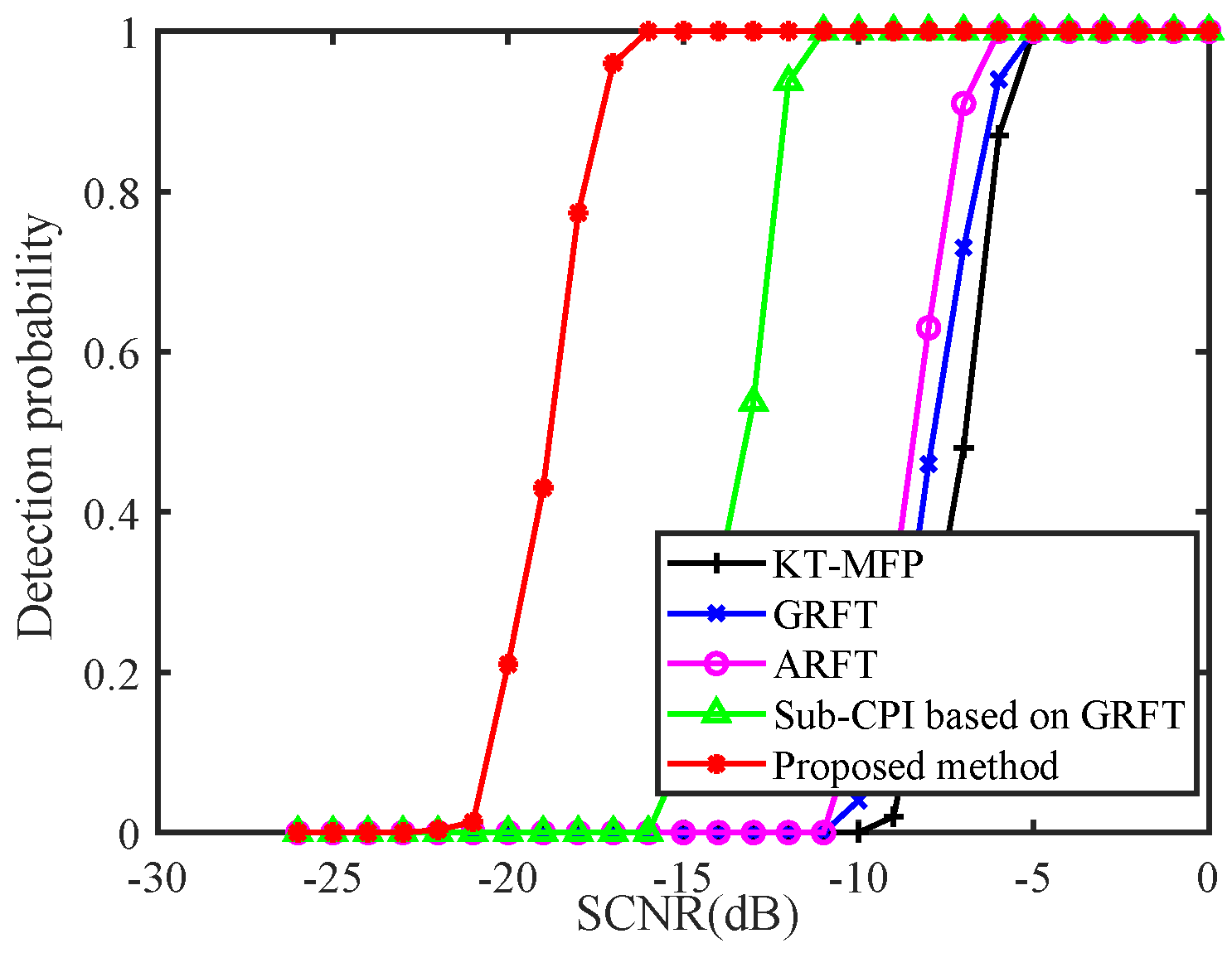
3.2. Comparison Results of Different Methods at Low SCNR

To compare the processing performance of KT-MFP, GRFT, ARFT, Sub-CPI STAP based on GRFT, and the proposed method, the simulation of a single target at the 19 dB SCNR after PC is given. The simulated parameters of the bistatic airborne radar system and the target are the same as those in Section 3.1. The processing results of the proposed method are provided in Figure 5. Comparing Figure 5a,b, we can see that sub-aperture space–time processing is effective and the target energy gathers some prominence from the background. By applying the MLRT, the target CI energy of the 25-th tertiary sub-aperture is still submerged in the clutter and noise, as given in Figure 5c. Then, the residual quadratic RCM and DM are compensated and the target energy of all sub-apertures is achieved in Figure 5d, where the SCNR after CI is about 4.36 dB.
Then, the KT-MFP, GRFT, ARFT, and sub-CPI STAP based on GRFT methods were also used to conduct a comparative experiment with the proposed method. Apparently, Figure 6a,b show that the KT-MFP and GRFT were unable to realize clutter suppression, thus the integrated target energy is buried in the background. In addition, because the ARFT could not eliminate the quadratic RCM and DM or the non-stationary clutter, it struggled to integrate the target energy, as shown in Figure 6c. The sub-CPI STAP based on GRFT is provided in Figure 6d. Although it could integrate the target energy from the clutter background and suppress the clutter to some extent, the SCNR of this method was only about 1.43 dB, which means this method struggles to carry out full data plane detection effectively. This is because this method does not consider the influence of clutter correlation and it has about a 5.8 dB SCNR loss, as compared with the proposed method in Figure 5d.

3.3. Multi-Target Simulation of the Proposed Method

This section describes a simulation for multiple targets using the proposed method. The motion parameters are list in Table 3. After the conversion, the equivalent initial slant range, velocity, and acceleration of target 1 are given as 9.49 km, 93.13 m/s, 47.28 m / s 2 , respectively. Furthermore, these parameters of target 2 were set as 15.15 km, −49.97 m/s, 51.88 m / s 2 . The PC result of these two targets is given in Figure 7a, where the targets’ energies are submerged. Then, the echoes of target 1 and target 2 are successively recovered in Figure 7b,c. Then, the 25-th tertiary sub-aperture accumulation results of target 1 and target 2 are given in Figure 7d,e, respectively. In these figures, the target energy within the sub-aperture is accumulated for the first time. Finally, Figure 7f,g separately illustrate the CI results of target 1 and target 2, where the targets’ energies are enhanced significantly to obtain a significant SCNR improvement.

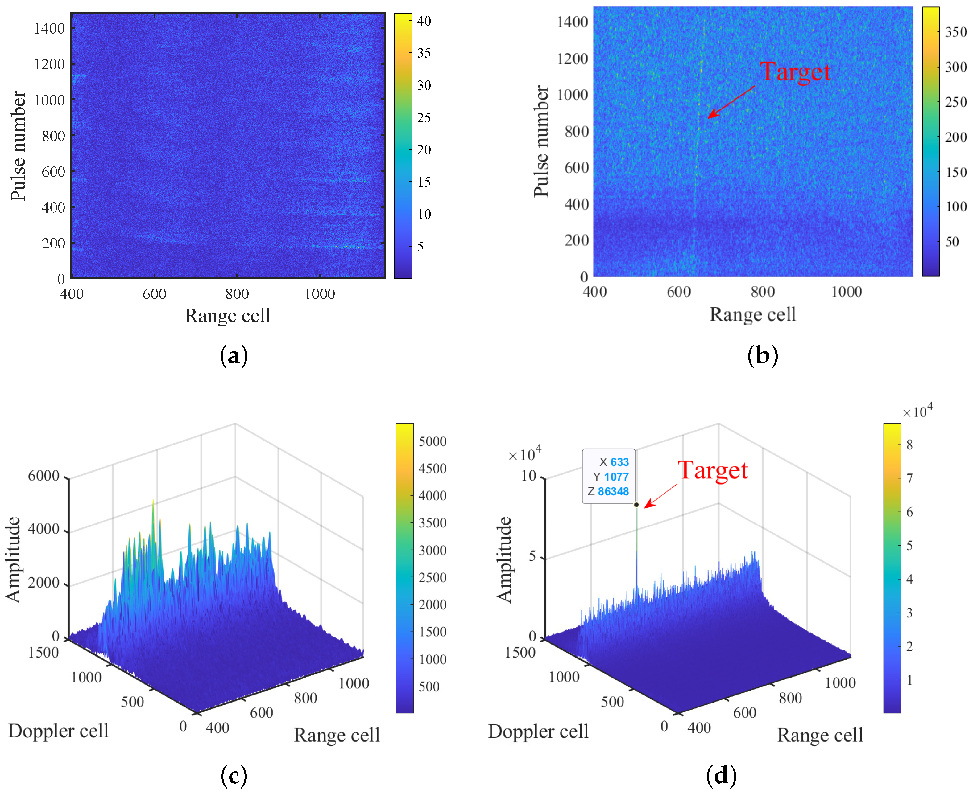
3.4. Real Data Processing Results

The real data processing results are given and compared for the typical aforementioned methods and the proposed one. Note that the data set was collected by two UAVs from an area of Chinese sea in 2018 and the main parameters of the transmitter and receiver are listed as follows: f c = 9 GHz, B = 5 MHz, and f s = 8 MHz. Figure 8a gives the PC result of one receiving channel with heavy sea clutter in which the target energy trajectory was difficult to obtain. Then, Figure 8b–e exhibit the processing results of KT-MFP, GRFT, ARFT, sub-CPI STAP based on GRFT, and the proposed method, respectively. Similar to simulation results, the CI result of the target energy is accumulated and focused well in Figure 8f, which is better than for the other methods. Particularly, the proposed method improved the output SCNR by about 4.82 dB as compared to sub-CPI STAP based on GRFT, which had the best clutter suppression and CI abilities from the other methods.

3.5. Target Detection Performance

In this section, we present the detection probability comparison results, which were obtained via 500 Monte Carlo experiments for each SCNR within the range of [−26 dB, 0 dB], as shown in Figure 9, where the false alarm probability was set as 10 4 . Taking into account the computational time cost, the pulse number was reset to 640 in this experiment. As shown in Figure 9, the detection probabilities of KT-MFP, GRFT, ARFT, sub-CPI based on GRFT, and the proposed method are given, where the detection ability of the presented method precedes that of the other methods. Particularly, when the detection probability P d = 0.8 , the proposed method required a lower SCNR after PC as compared to KT-MFP, GRFT, ARFT, and sub-CPI based on GRFT by about 11 dB, 10.6 dB, 10 dB, and 5 dB, respectively.
In our testing framework, the clutter data were simulated via the computer server and were added into the echo without the target. Then, the proposed method was executed 10,000 times to obtain the constant false alarm detection threshold T P F A when P F A = 10 4 . In addition, the echo with the target was also processed by the proposed method to achieve 500 detection sampling Monte Carlo trials under different SCNRs. For each trial, the detection peak value after processing the echo with the target (i.e., S process ) was compared to the threshold T P F A . When S process > T P F A , the detection result was set as 1. Otherwise, the result was set as 0. Finally, we calculated the average result for each SCNR and the detection probability was achieved.
In the Gaussian white noise background, the relationship between the detection probability P D , the false alarm probability P F A , and the output signal-to-noise ratio (SNR) can be stated as P D = P F A 1 1 + S N R . On the condition that P D = 0.8 and P F A = 10 4 , we can state that the output SNR is 15 dB. Because our method has the SNR gain of 640 pulse CI and 8 channel synthesis, the SNR gain is about 37 dB. Then, we can conclude that the theoretical SNR after PC is about 22 dB when P D = 0.8 and P F A = 10 4 in the Gaussian white noise condition. However, our method considers the non-stationary clutter condition and there is some compensation loss for RCM correction and all sub-aperture accumulation. Therefore, compared with the theoretical result, our method has an SCNR loss of about 4 dB, which is consistent with the detection results of the proposed method in Figure 9.

4. Discussion

Note that this paper aims to jointly suppress the clutter and realize coherent detection via sub-aperture processing. As for the CI process, our contribution is to realize the slow-time aperture division to ensure the influence of acceleration within each sub-aperture can be ignored. Then, the MLRT can be applied to correct the RCM within each sub-aperture. In addition, the matched filtering function is established to eliminate RCM/DM among different sub-apertures and coherent detection is realized by using all sub-apertures. In fact, we apply the existing MLRT method for RCM correction within each aperture and it is a link in our joint implementation processing system.

5. Conclusions

This paper focuses on the stationary clutter suppression and target detection problems and proposes a joint implementation method for a maneuvering target with an airborne bistatic radar. Stationary clutter Doppler compensation and sliding window processing are first applied within the sub-aperture. Then, the target linear RCM is corrected via MLRT to obtain the CI of each sub-aperture after the sub-aperture is divided in the slow-time direction and the residual RCM/DM among different sub-apertures is eliminated by MFP. Finally, the target energy of all sub-apertures is coherently integrated to realize target detection. The simulation and measured data processing results are provided to prove the validity and feasibility of the proposed method.
In this paper, there are some limitations in relation to the validation system of the proposed method. The connection between the detection probability, false alarm, and SCNR was not studied because of the non-stationary clutter and compensation loss for RCM correction and the accumulation of all sub-apertures. In addition, other Swerling models were not studied in this paper. In the future, we will study and find a novel CI method without using the traditional parameter searching idea to update our research. Moreover, we will continue to study echo modeling, clutter suppression, coherent integration, and variable false alarm detection for the target with other Swerling models in the airborne bistatic radar system [35,36]. Finally, we will try to reduce the computational complexity of processing to ensure the real-time requirements and possibility of application in operational contexts.

Author Contributions

Conceptualization, Z.S.; Methodology, X.J.; Software, H.Z.; Investigation, J.D.; Writing—original draft, Z.X.; Writing—review & editing, C.C.; Supervision, X.L.; Funding acquisition, G.C. All authors have read and agreed to the published version of the manuscript.

Funding

This work was supported in part by the National Natural Science Foundation of China under Grant 62101099 and 62371113, in part by the Chinese Postdoctoral Science Foundation under Grants 2021M690558, 2022T150100, 2018M633352, 2019T120825, in part by the Young Elite Scientist Sponsorship Program by CAST under Grant YESS20200082, and in part by the Natural Science Foundation of Sichuan Province under Grant 2023NSFSC1386.

Institutional Review Board Statement

Not applicable.

Informed Consent Statement

Not applicable.

Data Availability Statement

No new data were created or analyzed in this study. Data sharing is not applicable to this article.

Conflicts of Interest

The authors declare no conflicts of interest.

References

  1. Sun, X.; Wu, X.; Zhou, Q.; Zhang, L.; Wu, J. Airborne Radar Staggered PRF Coherent Processing Method for Down-Looking Target Detection. Remote Sens. 2023, 15, 3271. [Google Scholar] [CrossRef]
  2. Liu, J.; Liao, G.; Xu, J.; Zhu, S.; Zeng, C.; Juwono, F. Unsupervised Affinity Propagation Clustering Based Clutter Suppression and Target Detection Algorithm for Non-Side-Looking Airborne Radar. Remote Sens. 2023, 15, 2077. [Google Scholar] [CrossRef]
  3. Xu, G.; Zhou, S.; Yang, L.; Deng, S.; Wang, Y.; Xing, M. Efficient Fast Time-Domain Processing Framework for Airborne Bistatic SAR Continuous Imaging Integrated with Data-Driven Motion Compensation. IEEE Trans. Geosci. Remote Sens. 2021, 60, 5208915. [Google Scholar] [CrossRef]
  4. Xia, D.; Zhang, L.; Wu, T.; Hu, W. An Interference Suppression Algorithm for Cognitive Bistatic Airborne Radars. IEEE J. Syst. Eng. Electron. 2022, 33, 585–593. [Google Scholar] [CrossRef]
  5. Wang, C.; Zheng, J.; Jiu, B.; Liu, H. Model-and-Data-Driven Method for Radar Highly Maneuvering Target Detection. IEEE Trans. Aerosp. Electron. Syst. 2021, 57, 2201–2217. [Google Scholar] [CrossRef]
  6. Zhan, M.; Huang, P.; Zhu, S.; Liu, X.; Liao, G.; Sheng, J.; Li, S. A Modified Keystone Transform Matched Filtering Method for Space-Moving Target Detection. IEEE Trans. Geosci. Remote Sens. 2021, 60, 5105916. [Google Scholar] [CrossRef]
  7. Li, Z.; Ye, H.; Liu, Z.; Sun, Z.; An, H.; Wu, J.; Yang, J. Bistatic SAR Clutter-Ridge Matched STAP Method for Nonstationary Clutter Suppression. IEEE Trans. Geosci. Remote Sens. 2021, 60, 5216914. [Google Scholar] [CrossRef]
  8. Li, Z.; Li, S.; Liu, Z.; Yang, H.; Wu, J.; Yang, J. Bistatic Forward-Looking SAR MP-DPCA Method for Space—Time Extension Clutter Suppression. IEEE Trans. Geosci. Remote Sens. 2020, 58, 6565–6579. [Google Scholar] [CrossRef]
  9. Zhang, J.; Ding, T.; Zhang, L. Longtime Coherent Integration Algorithm for High-Speed Maneuvering Target Detection Using Space-Based Bistatic Radar. IEEE Trans. Geosci. Remote Sens. 2020, 60, 5100216. [Google Scholar] [CrossRef]
  10. Chen, W.; Xie, W.; Wang, Y. Range-Dependent Ambiguous Clutter Suppression for Airborne SSF-STAP Radar. IEEE Trans. Aerosp. Electron. Syst. 2021, 58, 855–867. [Google Scholar] [CrossRef]
  11. Ding, J.; Li, Y.; Li, M.; Wang, J. Focusing High Maneuvering Bistatic Forward-Looking SAR with Stationary Transmitter Using Extended Keystone Transform and Modified Frequency Nonlinear Chirp Scaling. IEEE J. Sel. Top. Appl. Earth Obs. Remote Sens. 2021, 58, 855–867. [Google Scholar] [CrossRef]
  12. Comite, D.; Pierdicca, N. Decorrelation of the Near-Specular Land Scattering in Bistatic Radar Systems. IEEE Trans. Geosci. Remote Sens. 2021, 60, 2000813. [Google Scholar] [CrossRef]
  13. Liu, Z.; Ye, H.; Li, Z.; Yang, Q.; Sun, Z.; Wu, J.; Yang, J. Optimally Matched Space-Time Filtering Technique for BFSAR Nonstationary Clutter Suppression. IEEE Trans. Geosci. Remote Sens. 2021, 60, 5210617. [Google Scholar] [CrossRef]
  14. Al-Sa’d, M.; Boashash, B.; Gabbouj, M. Design of an Optimal Piece-Wise Spline Wigner-Ville Distribution for TFD Performance Evaluation and Comparison. IEEE Trans. Signal Process. 2021, 69, 3963–3976. [Google Scholar] [CrossRef]
  15. Shi, R.; Wang, Y.; Wang, B.; Xiang, M. Frequency Modulation Nonlinearity Correction for FMCW SAL Based on WVD with Gradient Rotation Enhancement. IEEE Geosci. Remote Sens. Lett. 2023, 20, 6502205. [Google Scholar] [CrossRef]
  16. Li, Z.; Zhang, X.; Yang, Q.; Xiao, Y.; An, H.; Yang, H.; Wu, J.; Yang, J. Hybrid SAR-ISAR Image Formation via Joint FrFT-WVD Processing for BFSAR Ship Target High-Resolution Imaging. IEEE Trans. Geosci. Remote Sens. 2021, 60, 5215713. [Google Scholar] [CrossRef]
  17. Zhao, J.; Wang, Y. A Cross-range Scaling Method for ISAR Based on 2D MUSIC and WVD-Hough Transform. In Proceedings of the 2023 International Applied Computational Electromagnetics Society Symposium (ACES-China), Hangzhou, China, 15–18 August 2023; pp. 1–3. [Google Scholar]
  18. Li, X.; Cui, G.; Yi, W.; Kong, L. Coherent Integration for Maneuvering Target Detection Based on Radon-Lv’s Distribution. IEEE Signal Process. Lett. 2015, 22, 1467–1471. [Google Scholar] [CrossRef]
  19. Li, Y.; Su, T.; Zheng, J.; He, X. ISAR Imaging of Targets with Complex Motions Based on Modified Lv’s Distribution for Cubic Phase Signal. IEEE J. Sel. Topics Appl. Earth Observ. Remote Sens. 2015, 8, 4775–4784. [Google Scholar] [CrossRef]
  20. Zhang, Q.; Zhang, Y.; Sun, B.; Dong, Z.; Yu, L. Motion Parameters Estimation and HRRP Reconstruction of Maneuvering Weak Target for Wideband Radar Based on SKT-ELVD. IEEE Trans. Aerosp. Electron. Syst. 2022, 59, 2752–2763. [Google Scholar] [CrossRef]
  21. Chen, X.; Guan, J.; Liu, N.; He, Y. Maneuvering Target Detection via Radon-Fractional Fourier Transform-Based Long-Time Coherent Integration. IEEE Trans. Signal Process. 2014, 62, 939–953. [Google Scholar] [CrossRef]
  22. Chen, Z.; He, C.; Zhao, C.; Xie, F. Using SVD-FRFT Filtering to Suppress First-Order Sea Clutter in HFSWR. IEEE Geosci. Remote Sens. Lett. 2017, 14, 1076–1080. [Google Scholar] [CrossRef]
  23. Chen, S.; Lin, Y.; Yuan, Y.; Li, X.; Hou, L.; Zhang, S. Suppressive Interference Suppression for Airborne SAR Using BSS for Singular Value and Eigenvalue Decomposition Based on Information Entropy. IEEE Trans. Geosci. Remote Sens. 2023, 61, 5205611. [Google Scholar] [CrossRef]
  24. Blasone, G.; Colone, F.; Lombardo, P.; Wojaczek, P.; Cristallini, D. Passive Radar DPCA Schemes with Adaptive Channel Calibration. IEEE Trans. Aerosp. Electron. Syst. 2020, 56, 4014–4034. [Google Scholar] [CrossRef]
  25. Ma, C.; Hu, X.; Yeo, T.S.; Ng, B.P.; Zhang, Q. Matrix Ill-Condition Analysis in Spectrum Recovery of DPCA HRWS SAR Imaging. IEEE Geosci. Remote Sens. Lett. 2018, 16, 55–59. [Google Scholar] [CrossRef]
  26. Huang, P.; Zou, Z.; Xia, X.-G.; Liu, X.; Liao, G. A Novel Dimension-Reduced Space—Time Adaptive Processing Algorithm for Spaceborne Multichannel Surveillance Radar Systems Based on Spatial—Temporal 2-D Sliding Window. IEEE Trans. Geosci. Remote Sens. 2022, 60, 5109721. [Google Scholar] [CrossRef]
  27. Klintberg, J.; McKelvey, T.; Dammert, P. A Parametric Approach to Space-Time Adaptive Processing in Bistatic Radar Systems. IEEE Trans. Aerosp. Electron. Syst. 2021, 58, 1149–1160. [Google Scholar] [CrossRef]
  28. Zhan, M.; Zhao, C.; Qin, K.; Huang, P.; Fang, M.; Zhao, C. Subaperture Keystone Transform Matched Filtering Algorithm and Its Application for Air Moving Target Detection in an SBEWR System. IEEE J. Sel. Top. Appl. Earth. Obs. Remote Sens. 2023, 16, 2262–2274. [Google Scholar] [CrossRef]
  29. Lin, Y.; Qiu, X.; Li, H.; Wang, W.; Jiao, Z.; Ding, C. Channel Migration Correction for Low-Altitude Airborne SAR Tomography Based on Keystone Transform. IEEE Geosci. Remote Sens. Lett. 2023, 20, 4011805. [Google Scholar] [CrossRef]
  30. Sun, Z.; Li, X.; Yi, W.; Cui, G.; Kong, L. A Coherent Detection and Velocity Estimation Algorithm for the High-Speed Target Based on the Modified Location Rotation Transform. IEEE J. Sel. Top. Appl. Earth. Obs. Remote Sens. 2018, 11, 2346–2361. [Google Scholar] [CrossRef]
  31. ÇUlha, O.; Tanik, Y. Low Complexity Keystone Transform and Radon Fourier Transform Utilizing Chirp-Z Transform. IEEE Access 2020, 8, 105535–105541. [Google Scholar] [CrossRef]
  32. Li, H.; Liao, G.; Xu, J.; Zeng, C. Sub-CPI STAP based Clutter Suppression and Target Refocusing with Airborne Radar System. Digit. Signal Process. 2022, 123, 103418. [Google Scholar] [CrossRef]
  33. Huang, P.; Zou, Z.; Xia, X.; Liu, X.; Liao, G.; Xin, Z. Multichannel Sea Clutter Modeling for Spaceborne Early Warning Radar and Clutter Suppression Performance Analysis. IEEE Trans. Geosci. Remote Sens. 2020, 59, 8349–8366. [Google Scholar] [CrossRef]
  34. Yuan, H.; Xu, H.; Duan, K.; Xie, W.; Wang, Y. Cross-Spectral Metric Smoothing-Based GIP for Space-Time Adaptive Processing. IEEE Geosci. Remote Sens. Lett. 2018, 16, 1388–1392. [Google Scholar] [CrossRef]
  35. Grossi, E.; Lops, M.; Venturino, L. Detection Rate Optimization for Swerling Targets in Gaussian Noise. IEEE Trans. Aerosp. Electron. Syst. 2019, 55, 2054–2065. [Google Scholar] [CrossRef]
  36. Wang, J.; Ye, J.; Hua, G. The Optimal Detector of Distributed MIMO Radar under Swerling-Chi Scattering Models. IEEE Geosci. Remote Sens. Lett. 2020, 17, 1129–1133. [Google Scholar] [CrossRef]
Figure 1. Three-dimensional geometric configuration of airborne bistatic radar and maneuvering target.
Remotesensing 16 01379 g001
Figure 2. Flow chart of signal processing.
Remotesensing 16 01379 g002
Figure 3. The i-th primary sub-aperture echo data within the correlation time interval.
Remotesensing 16 01379 g003
Figure 4. Single target simulation results for the proposed method at the −7 dB SCNR. (a) PC result. (b) Sub-aperture space–time filtering. (c) Target echo signal recovery. (d) CI result of the 25-th tertiary sub-aperture. (e) CI result of all sub-apertures.
Remotesensing 16 01379 g004
Figure 5. Single target simulation results for the proposed method at the −19 dB SCNR. (a) PC result. (b) Target echo signal recovery. (c) CI result of the 25-th tertiary sub-aperture. (d) CI result of all sub-apertures.
Remotesensing 16 01379 g005
Figure 6. Single target simulation results for several existing methods at the −19 dB SCNR. (a) KT-MFP. (b) GRFT. (c) ARFT. (d) Sub-CPI STAP based on GRFT.
Remotesensing 16 01379 g006
Figure 7. Multi-target simulation results for the proposed method. (a) PC result. (b) Echo signal recovery of target 1. (c) Echo signal recovery of target 2. (d) CI result of the 25-th sub-aperture for target 1. (e) CI result of the 25-th tertiary sub-aperture for target 2. (f) CI result of all sub-apertures for target 1. (g) CI result of all sub-apertures for target 2.
Remotesensing 16 01379 g007
Figure 8. Real data processing results. (a) PC result. (b) KT-MFP. (c) GRFT. (d) ARFT. (e) Sub-CPI STAP based on GRFT. (f) Proposed method.
Remotesensing 16 01379 g008
Figure 9. Detection performance.
Remotesensing 16 01379 g009
Table 1. Parameters of the bistatic airborne radar system.
ParametersValue
Carrier frequency0.2 GHz
Range bandwidth5 MHz
Sampling frequency10 MHz
PRF500 Hz
CPI3 s
Pulse width10 µs
Velocity of transmitter(−80, 95, 0) m/s
Velocity of receiver(−80, 95, 0) m/s
The initial position coordinates of the transmitter(0.4, 16.5, 5) km
The initial position coordinates of the receiver(0.2, 10, 5) km
Table 2. Motion parameters of maneuvering target.
ParametersValue
The initial position coordinates(−0.1, 4, 3) km
The initial velocity(400, −60, 200) m/s
The acceleration(−3, −10, 10) m / s 2
Table 3. Parameters of targets.
ParametersTarget 1Target 2
The initial position coordinates(0.1, 4, 3) km(−0.1, −1, 0) km
The initial velocity(400, −60, 200) m/s(400, 135, 0) m/s
The acceleration(−30, −12.5, 10) m / s 2 (−30, −12.5, 0) m / s 2
Disclaimer/Publisher’s Note: The statements, opinions and data contained in all publications are solely those of the individual author(s) and contributor(s) and not of MDPI and/or the editor(s). MDPI and/or the editor(s) disclaim responsibility for any injury to people or property resulting from any ideas, methods, instructions or products referred to in the content.

