Article

A Micro-Motion Parameters Estimation Method for Multi-Rotor Targets without a Prior

1
Information and Navigation College, Air Force Engineering University, Xi’an 710077, China
2
Xi’an Electronic Engineering Research Institute, Xi’an 710100, China
3
Chinese Flight Test Establishment, Xi’an 710089, China
*
Author to whom correspondence should be addressed.
Remote Sens. 2024, 16(8), 1409; https://doi.org/10.3390/rs16081409
Submission received: 21 March 2024 / Revised: 12 April 2024 / Accepted: 12 April 2024 / Published: 16 April 2024

Abstract

:
Multi-rotor aircraft have the advantages of a simple structure, low cost, and flexible operation in the unmanned aerial vehicle (UAV) family, and have developed rapidly in recent years. Radar surveillance and classification of the growing number of multi-rotor aircraft has become a challenging problem due to their low-slow-small (LSS) characteristics. Estimation of the blade number is an important step in distinguishing LSS targets. However, most of the current research on micro-motion parameters estimation has focused on the analysis of rotational frequency, length, and the initial phase of blades with a prior of blade number, affecting its ability to identify LSS targets. In this article, a micro-motion parameters estimation method for multi-rotor targets without a prior is proposed. On the basis of estimating the flashing frequency of the blades, a validation function is constructed through spectral analysis to judge the number of blades, and then the rotational frequency is estimated. The blade length is calculated by estimating the maximum Doppler shift. Moreover, the variational mode decomposition (VMD)-based atomic scaling orthogonal matching pursuit (AS-OMP) method is jointly applied to estimate the blade length when suffering from the low PRF and insufficient SNR conditions. Extensive experiments on the simulated and measured data demonstrate that the proposed method outperforms robust micro-motion parameter estimation capability in low PRF and insufficient SNR conditions compared to the traditional time-frequency analysis methods.

1. Introduction

Unmanned aerial vehicles (UAVs), due to their safety, reliability, and flexibility, open up a new space for human activities between traditional aircraft and the ground, and have a significantly broad development prospect in the future. Multi-rotor aircraft have the advantages of a simple structure, low cost, and flexible operation in the UAV family, and have developed rapidly in recent years, emerging in many fields such as agriculture, aerial photography, surveillance, rescue, forestry, environmental protection, and even military operations [1]. At the same time, the increasing demand for the detection, identification, monitoring, and management of various cooperative and non-cooperative multi-rotor aircraft has become a serious challenge for governmental administrations and military researchers in various countries [2,3,4].
For the multi-rotor targets flying in urban and field areas, due to the strong environmental clutter, background noise, and various interfering targets, the detection performance of radar is seriously affected by the high false alarm rate. The tiny motion other than the main body translational motion caused by rotor rotation during the flight of a multi-rotor target is a typical micro-motion [5]. This kind of micro-motion produces the micro-Doppler (m-D) effect by periodic modulation on the body echo of the multi-rotor target, which becomes an important means to extract the fine features of the target and overcome the radar detection difficulties [6,7].
The m-D effects on rotating parts of radar targets first gained attention in the field of inverse synthetic aperture radar (ISAR) imaging due to their contamination of imaging results. Zhang et al. [8] applied the Hough transform (HT) to separate the spectrum of rotating parts and nonrotating parts, which can obtain a highly focused ISAR image of a target with rotating parts. Luo et al. [9] improved the HT method associated with time-frequency analysis and proposed an m-D signature extraction method for ISAR imaging. In the meantime, Bai et al. [10,11] put forward a complex-valued inverse Radon transform and eventually realized the high resolution and three-dimensional ISAR imaging of targets with rotating parts.
With the successful application of micro-motion component separation in ISAR high-resolution ISAR imaging and the continuous development of m-D signature refinement analysis methods, a large number of studies have emerged on the extraction of m-D signatures and the estimation of micro-motion parameters in rotary targets, such as the S-method-based Viterbi algorithm [12], the Fourier–Bessel transform with time–frequency analysis [13], the intrinsic mode function-based sparse recovery method [14,15], and the synchrosqueezing phase analysis method [16]. A network of passive radar receivers utilizing multistatic geometry of five passive physical channels was established for the analysis of m-D signatures of helicopters, and the main parameters—such as the number of blades, rotating speed, and length of the blades—can be estimated. The ISAR imaging was obtained except for the complex construction [17]. Aiming to capture the high rotating rate of small UAVs, both continuous wave (CW) and frequency modulation continuous wave (FMCW) radars operating at 94 GHz were processed to extract m-D signatures. The experiments with these show that they can tell the UAVs from birds, but their estimation of the rotating frequency through short-time frequency transform (STFT) and helicopter rotor modulation (HERM) is not very accurate [18]. In [19], a W-band radar operating at 92.16 GHz was adopted to estimate the blade length and rotational frequency of a UAV based on the STFT method, but the number of blades was not estimated. Compared to STFT, HERM has been widely adopted due to its strong robustness in estimating the rotating frequency of multi-rotor targets in noisy environments [20].
In addition to this, scholars have done a lot of very valuable work on micro-motion parameter estimation for multi-rotor targets. Zeus et al. [21] measured the UAV propeller length; Fang et al. [22] estimated the rotational frequency and initial phase of the UAV blades; Kang et al. [23] estimated the UAV’s blade length and rotational frequency based on the Doppler spectrum; and [24,25] proposed a method for estimating the rotational frequency of UAV blades. Bennett et al. [26] modeled the aerodynamics of UAV m-D signatures’ point amounts. Moreover, several methods and systems for classifying drones and birds of prey identification are described in [27,28,29,30,31].
Distinguishing between UAV and flying bird targets is the main problem in low-slow-small target classification and recognition, and estimating the number of multi-rotor target blades is a key step in solving this problem. However, none of the methods described above have been able to completely estimate the number of blades, rotational frequency, and blade length of a multi-rotor target without a prior. To fill this vacancy, a micro-motion parameter extracting method for multi-rotor targets without a prior is proposed in this paper. The specific contributions of this paper are as follows:
(1)
To the best of our knowledge, this is the first method for estimating the number of blades of a multi-rotor target based on spectral analysis. In conjunction with this approach, a micro-motion parameters extracting method for multi-rotor targets without a prior is proposed, which gains the ability to completely estimate the number of blades, rotational frequency, and blade length without a prior;
(2)
Considering the situation of inadequate PRF or sampling frequency and the harsh noisy environment with insufficient SNR, the proposed method combined with the variational mode decomposition (VMD)-based atomic scaling orthogonal matching pursuit (AS-OMP) algorithm can still completely extract three types of micro-motion parameters;
(3)
Compared to the HERM-based robust micro-motion parameter estimation method, the proposed method also has a comparative advantage in terms of computational efficiency with the highest accuracy of all micro-motion parameters estimation;
(4)
The performance of the proposed method has been validated in experiments conducted on three types of UAVs from different sources, ensuring it has good robustness and wide application prospects.
The rest of this article is organized as follows. In Section 2, the signal model is introduced, and the micro-motion feature extraction method for multi-rotor targets is presented. Section 3 demonstrates the experimental results and the analysis of simulated and measured data. In Section 4, some remaining shortcomings of the proposed method and future work are discussed. Section 5 draws a conclusion.

2. Micro-Motion Feature Extraction Method for Multi-Rotor Targets
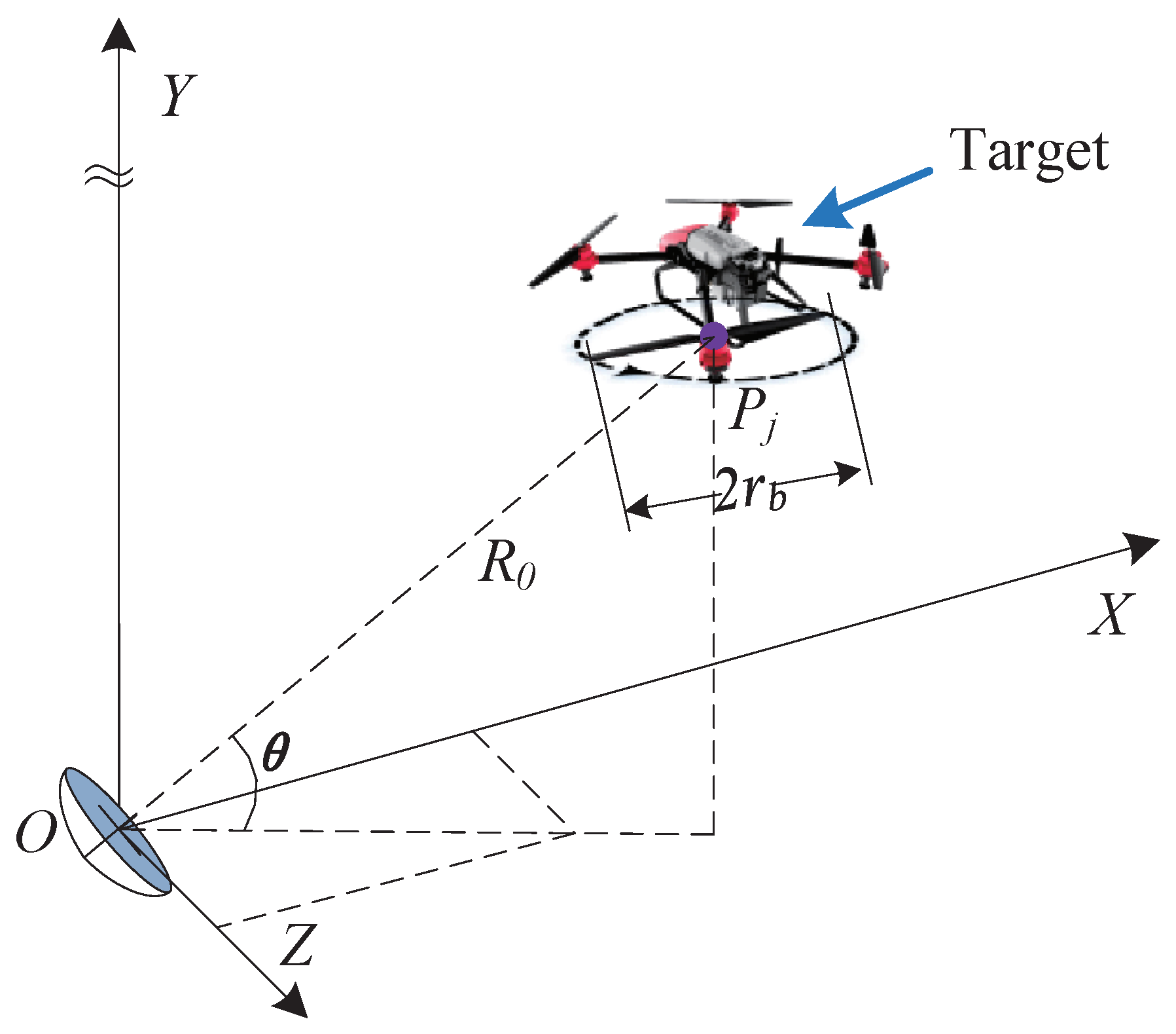
2.1. Signal Model

As shown in Figure 1, a typical scenario of a single-based radar detecting a multi-rotor UAV is constructed. The coordinate origin of radar is denoted by O, and the rotational center of the j-th rotor is denoted by P j , between which the distance is denoted by R 0 . β is the angle between the rotating plane of the blade and the radar line of sight, and r b is the blade length of the rotors.
The radar transmitting signal is represented in Equation (1), in which f c is the frequency of the carrier wave.
s ( t ) = exp ( j 2 π f c t )
The echo signal of the i-th blade of the j-th rotor can be expressed as Equation (2),
s i , j ( t ) = σ j exp ( j π f c c r b sin θ cos ( w b t φ i φ j ) ) sin c ( π f c c r b sin θ cos ( w b t φ i φ j ) )
in which c is the speed of light, θ is the radar line-of-sight pitch angle, σ j is the scattering coefficient of the j-th rotor; it can be expressed in Equation (3),
σ j = exp ( j 2 π f c c r j ) .
In Equations (2) and (3), φ j is the initial phase of the j-th rotor, φ i is the initial phase of the i-th blade, r j is the distance from the rotational center of the j-th rotor to the radar, and ω b is the angular rotational frequency, which can be expressed as Equation (4),
w b = 2 π f b
in which f b is the rotational frequency of the blade.
The echo signal can be transformed to the frequency domain by the fast Fourier transform (FFT), and the result can be expressed as Equation (5),
S i , j ( f ) = F ( f ) σ j exp ( j 2 π f ( φ i w b + φ j w b ) ) = F ( f ) σ j exp ( j 2 π f f b ( φ i + φ j ) )
in which F ( f ) is the body echo signal of the blade in the frequency domain, and it can be expressed as Equation (6).
F ( f ) = F F T [ exp ( j π f c c r b sin θ cos ( w b t ) ) sin c ( π f c c r b sin θ cos ( w b t ) ) ] .
Then, the echo signal of a multi-rotor target in the frequency domain can be expressed as Equation (7).
S ( f ) = j = 1 M i = 1 N F ( f ) σ j exp ( j 2 π f ( φ i w b + φ j w b ) ) = F ( f ) j = 1 M σ j exp ( j 2 π f φ j w b ) i = 1 N exp ( j 2 π f φ i w b ) = F ( f ) ( i = 1 N exp ( j 2 π f φ i w b ) ) ( j = 1 M σ j exp ( j 2 π f φ j w b ) )
where M, N denote the number of rotors and blades, respectively. The difference between the initial phases of the blades should be 2 π / N . In the simulation, for ease of calculation, the initial phase of the blades is generally set as φ i = ( i 1 ) · 2 π / N , i = 1 , 2 , , N .
Now, the echo signal of a multi-rotor target is divided into three parts, the latter two being the phase term of the blades and rotors, respectively. By further observing and analyzing the middle part of Equation (7), i.e., the phase term of the blades, the characteristics of different kinds of blades can be obtained to provide ideas for the estimation of micro-motion parameters of multi-rotor targets.

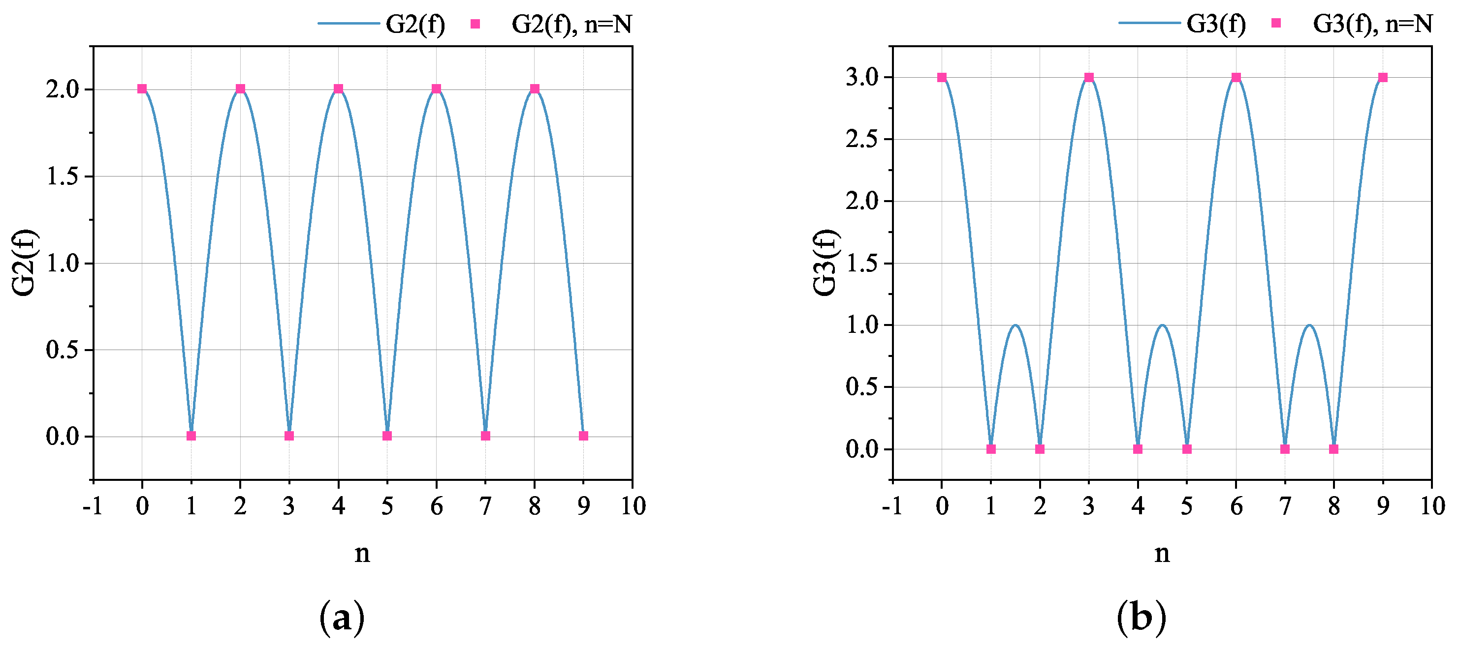
2.2. Estimation of the Number of Blades

Before further analyzing the micro-motion characteristics of the target, it is necessary to clarify the target to which this method will be applied. The multi-rotor target to be recognized needs to satisfy the following assumptions:
(1)
Multiple rotors of the target are structurally consistent;
(2)
Multiple blades of a single rotor are structurally consistent;
(3)
Neighboring blades of a single rotor have the same initial phase difference.
Take the middle part of Equation (7) separately and write it as Equation (8).
G ( f ) = i = 1 N exp ( j 2 π f φ i w b ) .
Substitute Equation (4) into Equation (8) and rewrite it as Equation (9).
G ( f ) = i = 1 N exp ( j 2 π f f b φ i ) .
It can be seen that G ( f ) is in the form of an accumulation of several rotational factors, and the order of the accumulation depends on N, which is the same as the number of blade initial phases φ i , i.e., the number of blades N b in each rotor.
The forms of G ( f ) and the numbers of blades of the multi-rotor targets are in one-to-one correspondence, and the accumulation form of G ( f ) determines that it has a fixed zero position in the case of consecutive values, i.e., the numbers of blades of the multi-rotor targets are in one-to-one correspondence with the distributions of zeros of different G ( f ) , and it is easy to know that these distributions of zeros are independent of each other.
Through the above analysis, it is natural to think that the number of blades of a multi-rotor target can be determined by analyzing the zero distribution or the undulating characteristics in the frequency domain of the radar echoes. These undulating characteristics are further analyzed using two-bladed and three-bladed multi-rotor targets as examples, respectively.
For a two-bladed multi-rotor target, G ( f ) can be written as G 2 ( f ) in Equation (10).
G 2 ( f ) = i = 1 N = 2 exp ( j π f f b φ i ) = 1 + exp ( j π f f b ) .
A special case is given here to illustrate the fluctuation characteristics of G 2 ( f ) , when the frequency–domain resolution satisfies Δ f = f b , then G 2 ( f ) satisfies Equation (11).
f = n · f b G 2 ( f ) = 0 , n = 2 N 1 , N N * 2 , n = 2 ( N 1 ) , N N *
For a three-bladed multi-rotor target, G ( f ) can be written as G 3 ( f ) in Equation (12).
G 3 ( f ) = i = 1 N = 3 exp ( j π f f b φ i ) = 1 + exp ( j 2 π 3 f f b ) + exp ( j 4 π 3 f f b )
Here, we also provide a special case to illustrate the fluctuation characteristics of G 3 ( f ) , when the frequency–domain resolution satisfies Δ f = f b , then G 3 ( f ) satisfies Equation (13).
f = n · f b G 3 ( f ) = 0 , n = 3 ( N 1 ) , N N * 3 , n 3 ( N 1 ) , N N *
Figure 2a,b plot a visual schematic of G 2 ( f ) and G 3 ( f ) . The blue curves show the fluctuation characteristics of G(f), and the red dots mark the values of G(f) when the frequency f is taken to be an integral multiple of the blade rotational frequency f b .
Based on the above theory, an efficient algorithm can be proposed to estimate the number of blades of a multi-rotor target. It is first necessary to estimate the blade flash frequency f flash of the target. When the target is in a hovering state, it has a unique flashing frequency because the rotational frequency of each rotor blade is the same. Depending on the scenario and echoed data, a time-frequency analysis method such as STFT, HERM, or FFT can be selected to estimate the f flash of the target.
After obtaining the target blade flashing frequency, the validation function can be constructed for different blade numbers N b . Equation (14) shows the validation function for two- and three-blade multi-rotor targets.
p 2 ( f ) = 1 + exp ( j π f f flash / 2 ) p 3 ( f ) = 1 + exp ( j 2 π 3 f f flash / 3 ) + exp ( j 4 π 3 f f flash / 3 ) .
Multiply the validation function and the frequency domain of the target echo; if there is no change or small change in the frequency domain, the number of blades corresponding to this validation function is the number of blades of the target. In practice, it is also possible to determine the zero position of the validation function corresponding to different numbers of blades and then extract the frequency points of the corresponding zero positions from the frequency domain of the echo for comparison; the smaller value corresponds to the validation function of the correct number of blades, and the value of frequency points for correct validation function will generally be smaller for one to two orders of magnitude than the others.
A key issue that requires further discussion is that since signals are finite in the time domain and periodically discrete in the frequency domain in practice, the implementation of the algorithm depends on whether the discrete samples in the frequency domain can fall on the zeros of the validation function. Obviously, it is very difficult to realize this requirement, but the proposed method is equally applicable as long as the following two requirements are met.
First, the frequency–domain resolution Δ f of the signal should be much smaller than the rotational frequency of the blade, as shown in Equation (15); second, the frequency domain of the signal on both sides of the zero point is a continuous change rather than a sudden change, which ensures that, even if the extraction of the zero point frequency deviates slightly, it still does not affect the final judgment.
Δ f f b .
The first point is easy to satisfy for real sampled signals, and the second point is also easy to satisfy because the frequency domain of the signal varies continuously on either side of the poles, and there are several orders of magnitude of differences between the extreme values and the extreme minima. These two points are the basis for the successful implementation of the algorithm.

2.3. Estimation of the Rotational Frequency and Blade Length

Estimates of blade rotation frequency and blade length need to be discussed in a categorized manner. When the radar is adequate and the signal-to-noise ratio of the data is sufficient, the blade flash frequency and the maximum Doppler shift can be extracted directly after the time-frequency analysis of the signal, such as FFT, VMD, STFT, HERM, and so on.
However, when the radar sampling frequency or pulse repetition frequency is insufficient, i.e., the maximum Doppler shift caused by the high-speed rotation of the blades is more than half of the sampling frequency or pulse repetition frequency, the radar echo signals of the multi-rotor target will have the phenomena of aliasing and coiling in the frequency or time-frequency domain, and it is difficult to effectively extract the blade flash frequency and the maximum Doppler shift at this time.
Moreover, when the signal-to-noise ratio of the radar echo signal is insufficient, the signal indicative of the maximum Doppler shift may be buried in the background noise. This results in an inability to efficiently extract the maximum Doppler shift, and consequently, the estimation of the blade length of the multi-rotor target is impossible.

2.3.1. Case A: Radar Data with Adequate Sampling Frequency or PRF and Sufficient SNR

For a multi-rotor hovering target, since the rotational frequencies of blades in each rotor are constant and have a unique blade flash frequency, provided that the number of blades N b and the blade flash frequency are known, its rotational frequency f b can be estimated by Equation (16).
f b = f flash N b .
For each blade of the rotors, when the radar beam illuminates it vertically, the radial velocity at the tip of the blade is at a maximum, at which time the Doppler frequency reaches its maximum, then the maximum Doppler frequency f dmax can be expressed as Equation (17),
f dmax = 4 π f b r b λ c o s θ
where θ denotes the pitch angle of the radar line of sight, λ denotes the wavelength of the radar signal, and the length of the blades r b can be calculated from Equations (16) and (17) using Equation (18).
r b = f dmax λ 4 π f b c o s θ .

2.3.2. Case B: Radar Data with Inadequate Sampling Frequency and PRF or Insufficient SNR
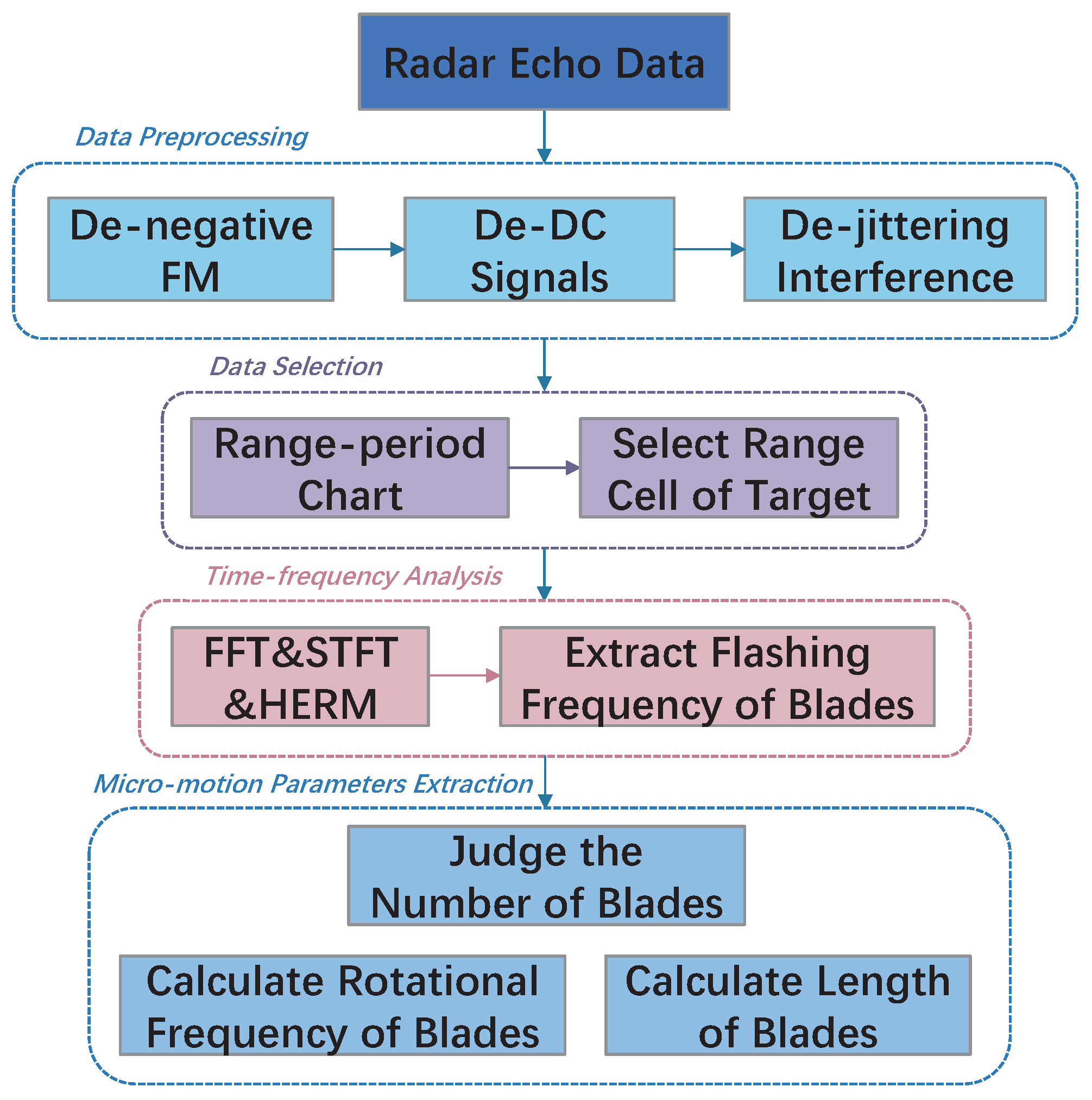
The above analysis shows that the estimation of the blade rotational frequency depends on the estimation of the flash frequency, and the estimation of the blade length depends on the estimation of the maximum Doppler shift. Therefore, the inability to estimate the two antecedent parameters when the sampling frequency or PRF is inadequate (sampling frequency in narrow-band radar and PRF in wide-band radar, harmonized below with PRF) or the SNR is insufficient will cause the above method to fail. To address this situation, the variational mode decomposition (VMD) is adopted to estimate the blade rotation frequency, after which an orthogonal matched perusing method based on atomic scaling (AS-OMP) is adopted to estimate the blade length.
The blade flash frequency extraction process is based on the VMD algorithm [32] and can be modeled as the optimization problem in Equation (19).
min s k ( t ) w k ( t ) k = 1 K | | t ( s k ( t ) ) exp ( j w t ) | | 2 2
where s k ( t ) represents the time-domain signal of the k-th spectral peak, w k ( t ) is the rotational angular frequency of the blade, K is the number of peaks; s d m 0 ( t ) is the segmented signal with the largest time-frequency spectral entropy.
The problem described in Equation (19) can be solved by the alternating direction method of multipliers (ADMM) to obtain an estimation of the k spectral peak frequencies wk. Then, the blade flash frequency of the multi-rotor target can be estimated by Equation (20).
f flash = 1 K 1 k = 1 K 1 ( diff ( w k 2 π ) ) .
Since the number of blades N b of the multi-rotor target has been estimated in Section 2.2, the rotational frequency of the blades f b can be calculated using Equation (16).
In the case of obtaining the target blade rotational frequency, the AS-OMP method [33,34] can be applied to estimate the blade length. A dictionary is first established based on the approximate range of the target blade length of the multi-rotor to be estimated as shown in Equation (21).
D = A i ( x )
where the i-th atom in the x-th scaling matching condition can be expressed as Equation (22).
A i ( x ) = sinc ( η x f c 2 l i ( x ) c cos ( ϕ n ( t ) α ) ) × exp ( j 4 π R 0 λ ) exp ( j η x f c 2 π l i ( x ) c cos β cos ( ϕ n ( t ) α ) )
where η x is the x-th scaling coefficient and η 1 = 1 , α is the azimuth angular of the rotating blade relative to the radar line of sight at the initial moment, l i ( x ) is the estimated value of the blade length at the x-th time, and ϕ n ( t ) is the phase of the n-th blade at the moment t. Then, the final estimate l i ( 1 ) of the blade length of the multi-rotor target can be obtained by solving Equation (23).
arg 1 g G max l i ( 1 ) x = 2 4 ( A i ( 1 ) + A i ( x ) ) .
In summary, the flowchart of the micromotion parameter extraction algorithm for multi-rotor targets can be drawn as Figure 3, and the method can be organized into the following four steps:
(1)
Data preprocessing. In order to acquire the target’s micro-motion signal, it is necessary to eliminate the negative frequency signal in the radar echo data, design a high-pass filter to remove the direct current (DC) components and a smoothing filter to reduce the jittering interference;
(2)
Data selection. After data preprocessing to remove interference, the range-period chart is plotted according to the approximate location of the target, making it clear where the target is located in terms of range cells, and the corresponding radar data can be extracted;
(3)
Time-frequency analysis. Extraction of blade flashing frequency f flash is the basis of micro-motion parameters estimation. Multi-rotor targets in a hovering state are generally extracted by time-frequency analysis methods such as FFT, STFT, and HERM due to the unique blade flashing frequency. In this paper, the proposed method does not need the number of blades N b for a prior and also does not need the integrated estimation of micro-motion parameters in the time-frequency analysis, so the FFT method is chosen for its highest computational efficiency;
(4)
Micro-motion parameters extraction. After obtaining the blade flashing frequency f flash , the blade validation function can be constructed to judge the number of target blades N b then the blade rotation frequency f b can be calculated by Equation (16), and finally the length of blades can be calculated by Equation (18).

3. Experimental Results and Analysis

In this section, we compare the proposed method with two extensively used traditional methods through simulation data experiments and measured data experiments in outdoor scenes, respectively. In addition, to better apply the proposed method to various situations of real-world data, all experiments were verified twice in the case of inadequate PRF and insufficient SNR. The results of the comparison experiments prove that the proposed method has obvious advantages in multi-rotor target micro-motion parameter extraction.

3.1. Experiments on Simulated Data

3.1.1. Introduction to the Simulation Experiments

Table 1 shows the main parameters of the radar signal and multi-rotor target in the simulation experiments. The simulation experiments use an X-band continuous wave (CW) radar with a carrier frequency of 1.8 GHz. The distance of the multi-rotor target is in the vicinity of 7645 m, which means the radar line-of-sight pitch angle can be roughly considered as 0 .
The maximum Doppler shift f d max = 791.6813 Hz of the simulation target can be calculated by Equation (17), and to ensure that no aliasing occurs in the frequency domain, the minimum sampling frequency needs to be not less than two times the maximum Doppler shift, i.e., f s m i n 2 f d m a x . Therefore, the sampling frequencies under the conditions of satisfying and not satisfying the sampling frequency conditions are set to 4096 Hz and 1024 Hz, respectively, in the simulation experiments. When background noise is present, only the maximum frequency point that is not covered by noise can be used as the maximum Doppler shift of the echo signal. If the edge frequencies are covered by noise, it is not possible to estimate the maximum Doppler frequency shift by means of spectral analysis. So, the critical value of the signal-to-noise ratio should be measured by covering the effective frequency points of the edges of the FFT. In practice, since it is impossible to confirm the energy magnitude of the FFT edge frequency points, a threshold value, such as 0.3 of the maximum frequency point energy, is generally given as a judgment criterion.
In order to illustrate the effectiveness and generalization of the proposed method more completely and in different scenarios, the simulation experiments are set up with two types of quadrotor targets with two blades and three blades, respectively, and validated under different PRF and SNR conditions. Three widely used methods were selected for comparative validation, namely FFT, STFT, and HERM methods. It should be noted that the tfrstft function in MATLAB is used to generate the time-frequency diagrams of STFT and HERM. The number of frequency bins and frequency smoothing windows of STFT and HERM are set as H STFT = 19 , N STFT = H STFT × 4 = 76 , H HERM = 199 , and N HERM = H HERM × 4 = 796 . In addition to that, due to the presence of aliasing or strong noise in the echo signals at low PRF and SNR conditions, the algorithm jointly applies the VMD and AS-OMP-based method for effective estimation of the target as a Doppler parameter.
The computer configuration used for the simulation experiments was as follows: 12th Gen Intel(R) Core(TM) i7-12700, 2.10 GHz, DDR4 RAM 32.0 GB, NVIDIA GeForce RTX 3070, Windows 11, MATLAB 2022a.

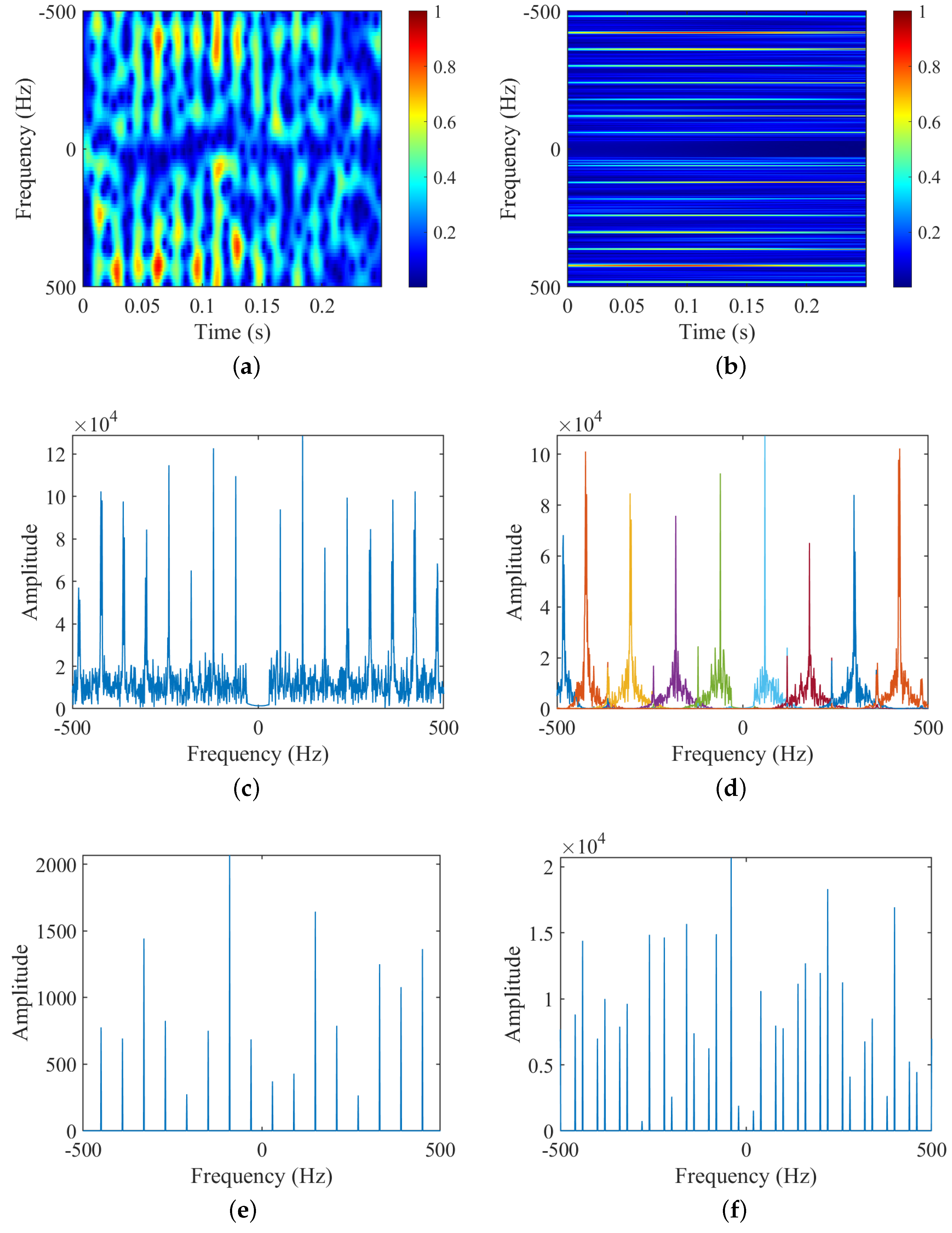
3.1.2. Experiment 1: Simulated Data with Adequate PRF and SNR for Two-Bladed Target
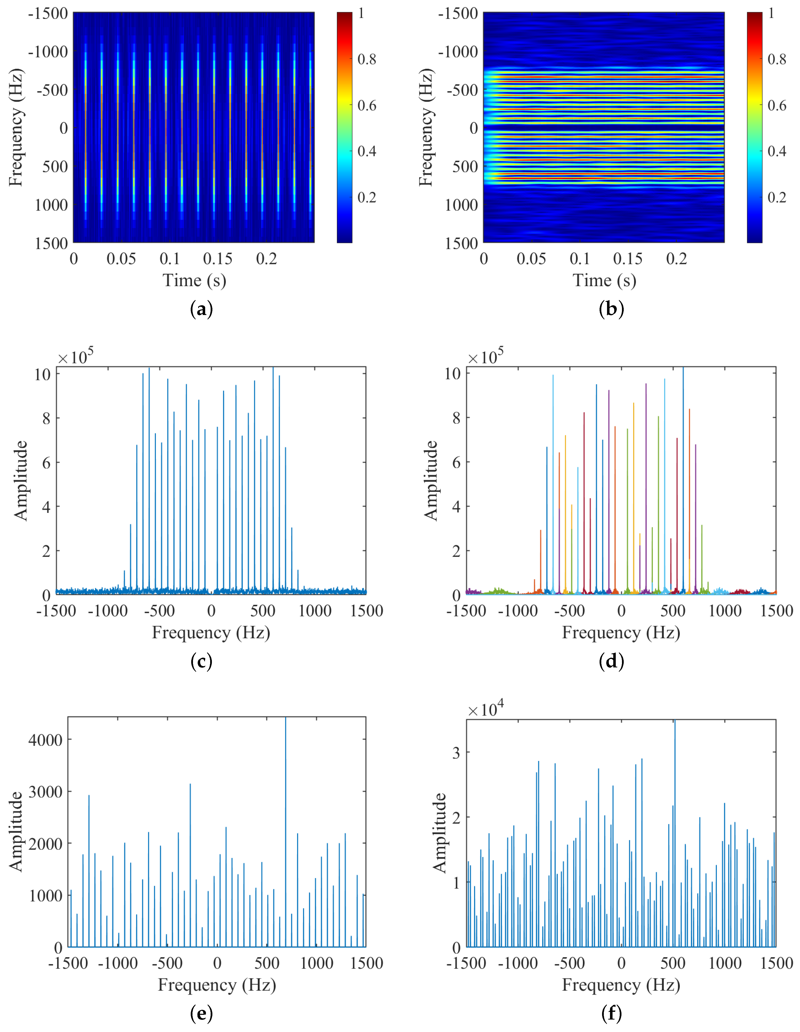
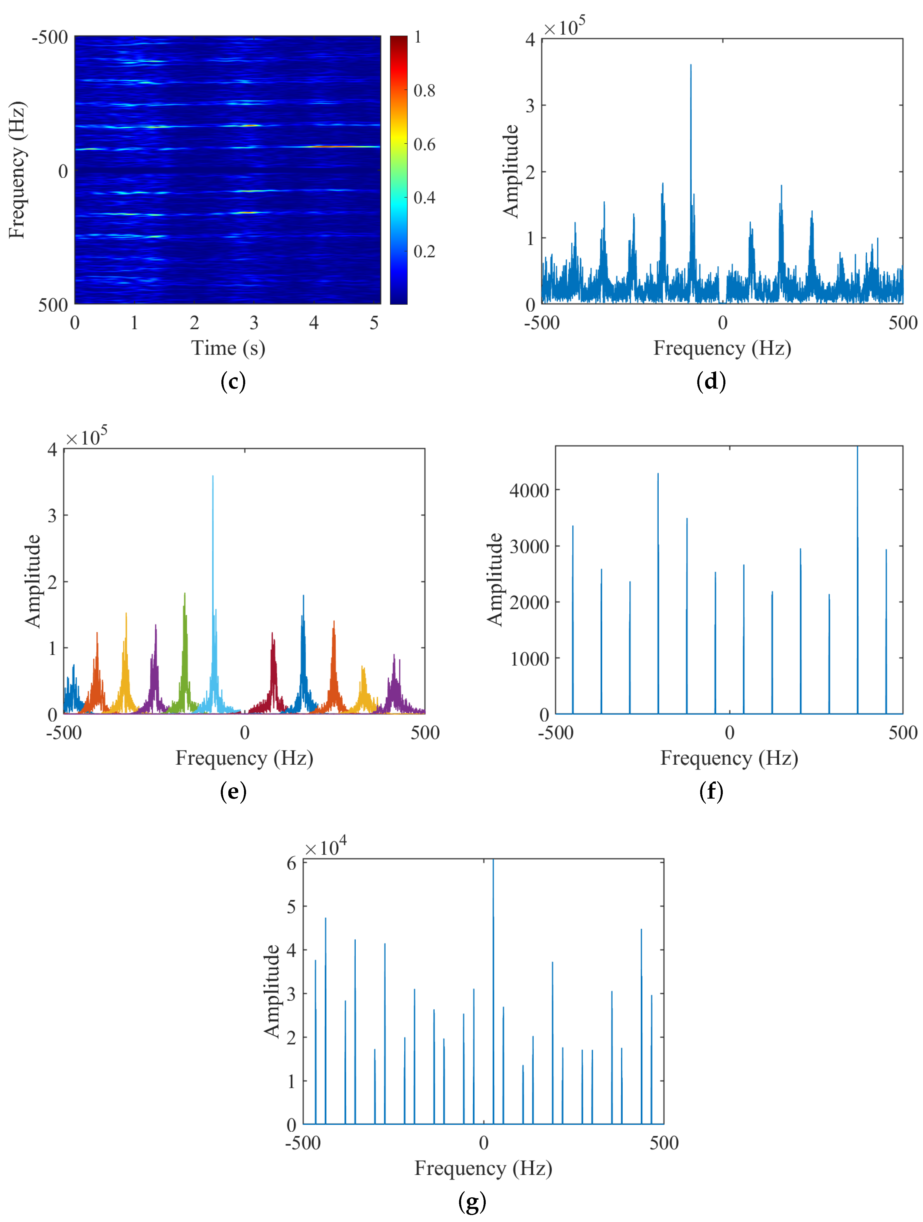
Figure 4 shows the results of several time-frequency analysis methods on simulated data of a two-bladed target with PRF at 4096 Hz and SNR at 10 dB. Table 2 shows the micro-motion parameters estimation results and computational consumption of the methods. From the time-frequency figures and estimated results, we can find that:
(1)
For the number of blades N b , the STFT in Figure 4a shows symmetric characteristics, from which it can be judged that N b is even, and the HERM in Figure 4b does not show any feature of the number of blades, and finally, combined with the frequency point amplitude of the multi-blade validation function in Figure 4e,f, it can be determined that N b is 2;
(2)
For the rotational frequency of blade f b , the ridges can be extracted from the time-frequency spectrograms of STFT and HERM in Figure 4a,b, and the spectral intervals can also be extracted from the FFT or VMD spectrograms in Figure 4c or d, which can be computed to obtain the blade flashing frequency f flash . And then, the STFT and HERM methods can calculate f b using Equation (16) based on the existing blade a priori information, and the results are 35.128 Hz and 25.025 Hz, respectively. While the FFT and VMD methods can calculate f b based on N b that have been judgmentally acquired, the estimated result is 35 Hz;
(3)
For the blade length r b , the maximum Doppler shifts f d are extracted for STFT, HERM, and the proposed method as 819.200 Hz, 781.022 Hz, and 790.000 Hz, respectively. Then, the blade length can be calculated according to Equation (18), and the results based on STFT, HERM, and the proposed method are 36.350 cm, 34.550 cm, and 34.930 cm, respectively;
(4)
Comprehensively comparing the three methods, only the proposed method can completely estimate the number of blades N b , rotational frequency f b , and blade length r b without a priori information, and has the highest parameter estimation accuracy, although the operation speed is slightly slower than that of the STFT method.
The results shown here demonstrate the completeness, accuracy, and relative computational efficiency of the micro-motion parameters extraction of the proposed method for a two-bladed target in adequate PRF and SNR conditions.

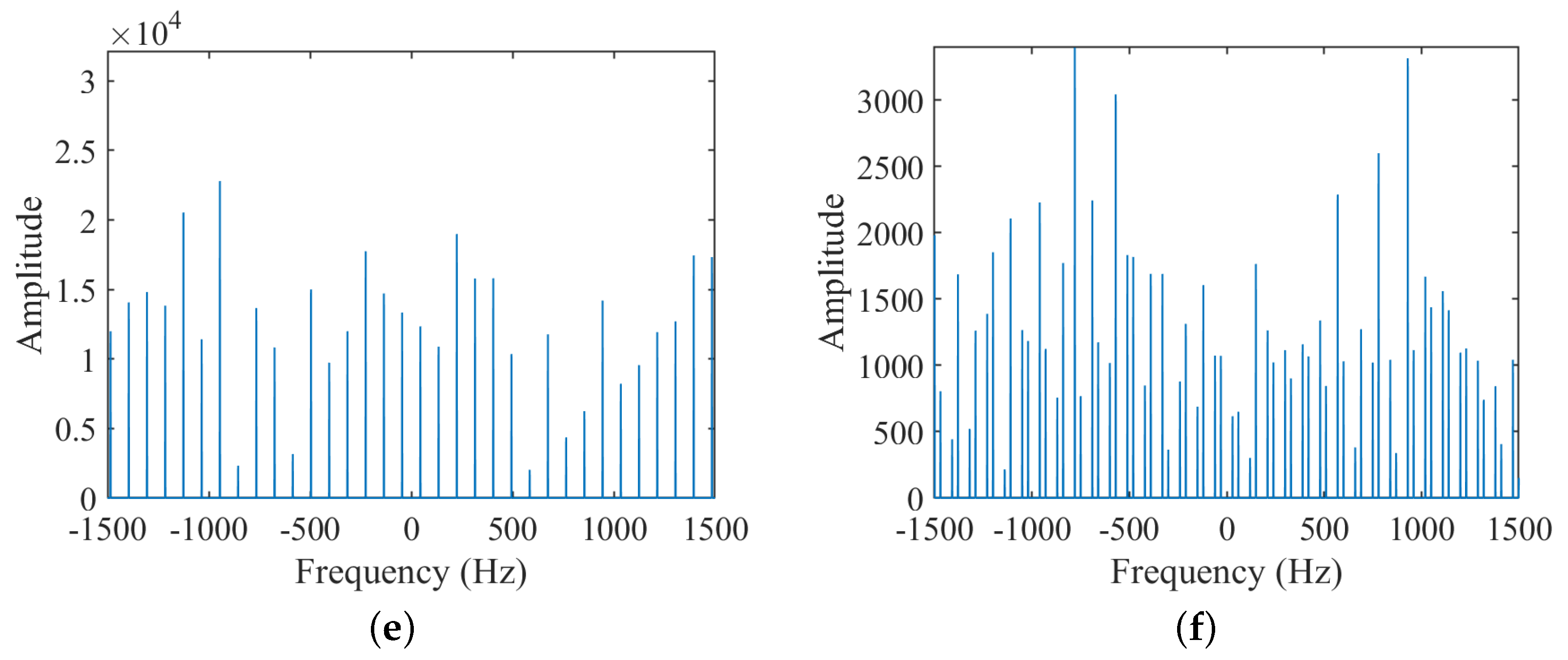
3.1.3. Experiment 2: Simulated Data with Inadequate PRF and SNR for Two-Bladed Target

Figure 5 shows the results of several time-frequency analysis methods on simulated data of a two-bladed target with inadequate PRF at 1024 Hz and SNR at 3 dB. Table 3 shows the micro-motion parameters estimation results and computational consumption of the methods. From the time-frequency figures and estimated results, we can find that:
(1)
For the number of blades N b , the STFT-based time-frequency spectrogram in Figure 5a is not capable of determining N b due to low SNR and PRF, and the HERM-based time-frequency spectrogram in Figure 5b is similarly not capable of determining N b . Finally, combined with the frequency point amplitude of the multi-blade validation function in Figure 5e,f, it can still be determined that N b is 2;
(2)
For the rotational frequency of blade f b , the ridges can be extracted from the time-frequency spectrograms of STFT in Figure 4a, but high-quality image clips need to be found. And the spectrograms of HERM, FFT, or VMD in Figure 4b, c, and d can still provide the extraction of the ridges or spectral lines to calculate the blade flashing frequency f flash clearly. The results for f b of the STFT, HERM, and FFT or VMD are 33.003 Hz, 30.251 Hz, and 30 Hz, respectively;
(3)
For the blade length r b , the maximum Doppler shift f d cannot be extracted due to the influence of low PRF and SNR. So, the VMD-based AS-OMP method needs to be applied to search the value of r b , according to the estimated r b by the three time-frequency analysis methods. As shown in Equation (21) to Equation (23), the blade length r b can be estimated as 33.326 cm, 33.917 cm, and 34.017 cm, respectively;
(4)
Comprehensively comparing the three methods, only the proposed method can completely estimate the number of blades N b , rotational frequency f b , and blade length r b without a priori information, and has the highest parameter estimation accuracy, although the operation speed is slightly slower than that of the STFT method.
The results shown here demonstrate the completeness, accuracy, and relative computational efficiency of the proposed method for extracting micro-motion parameters for a two-bladed target in inadequate PRF and SNR conditions.

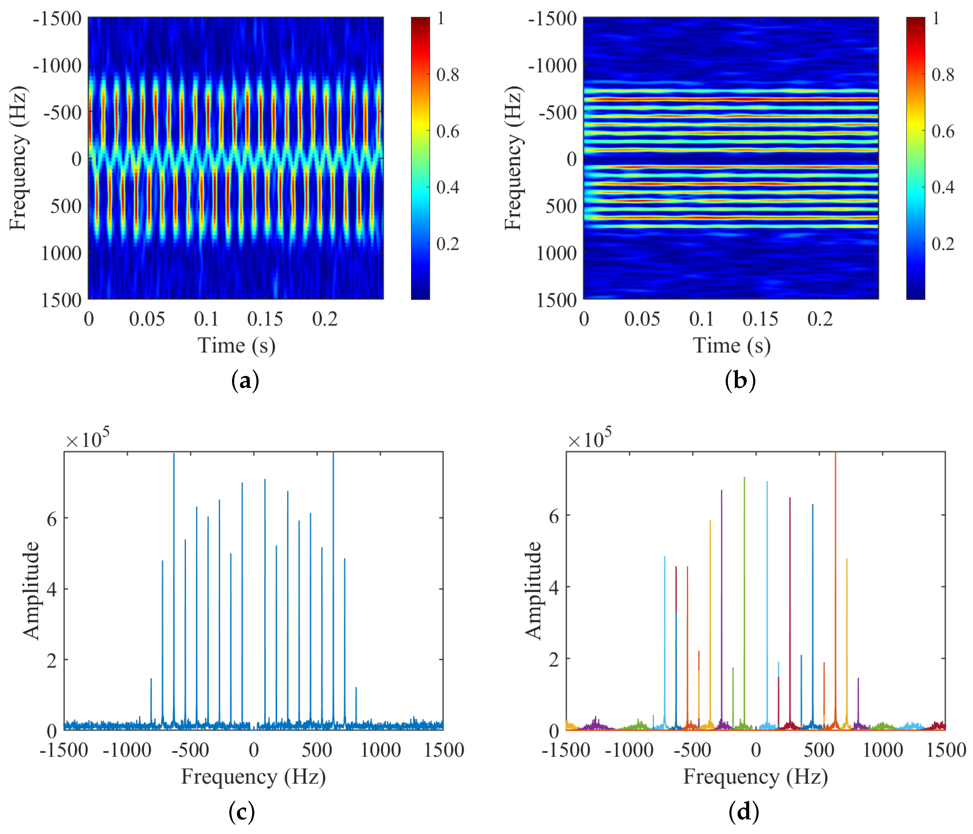
3.1.4. Experiment 3: Simulated Data with Adequate PRF and SNR for Three-Bladed Target

Figure 6 shows the results of several time-frequency analysis methods on the simulated data of a three-bladed target with PRF at 4096 Hz and SNR at 10 dB. Table 4 shows the micro-motion parameters estimation results and computational consumption of the methods. From the time-frequency figures and estimated results, we can find that:
(1)
For the number of blades N b , the STFT in Figure 6a shows alternating characteristics, from which it can be judged that N b is odd, and the HERM in Figure 6b does not show any feature of the number of blades, and finally, combining with the frequency point amplitude of the multi-blade validation function in Figure 6e,f, it can be determined that N b is 3;
(2)
For the rotational frequency of blade f b , the ridges can be extracted from the time-frequency spectrograms of STFT and HERM in Figure 6a,b, and the spectral intervals can also be extracted from the FFT or VMD spectrograms in Figure 6c or d, which can be computed to obtain the blade flashing frequency f flash . And then, the STFT and HERM methods can calculate f b using Equation (16) based on the existing blade a priori information, and the results are 30.560 Hz and 29.178 Hz, respectively. While the FFT and VMD methods can calculate f b based on the N b that have been judgmentally acquired, the estimated result is 30 Hz;
(3)
For the blade length r b , the maximum Doppler shifts f d are extracted for STFT, HERM, and the proposed method as 771.827 Hz, 722.143 Hz, and 810.000 Hz, respectively. Then, the blade length can be calculated according to Equation (18), and the results based on STFT, HERM, and the proposed method are 33.500 cm, 32.820 cm, and 35.810 cm, respectively;
(4)
Comprehensively comparing the three methods, only the proposed method can completely estimate the number of blades N b , rotational frequency f b , and blade length r b without a priori information, and has the highest parameter estimation accuracy, although the operation speed is slightly slower than that of the STFT method.
The results shown here demonstrate the completeness, accuracy, and relative computational efficiency of micro-motion parameters extraction of the proposed method for a three-bladed target in adequate PRF and SNR conditions.

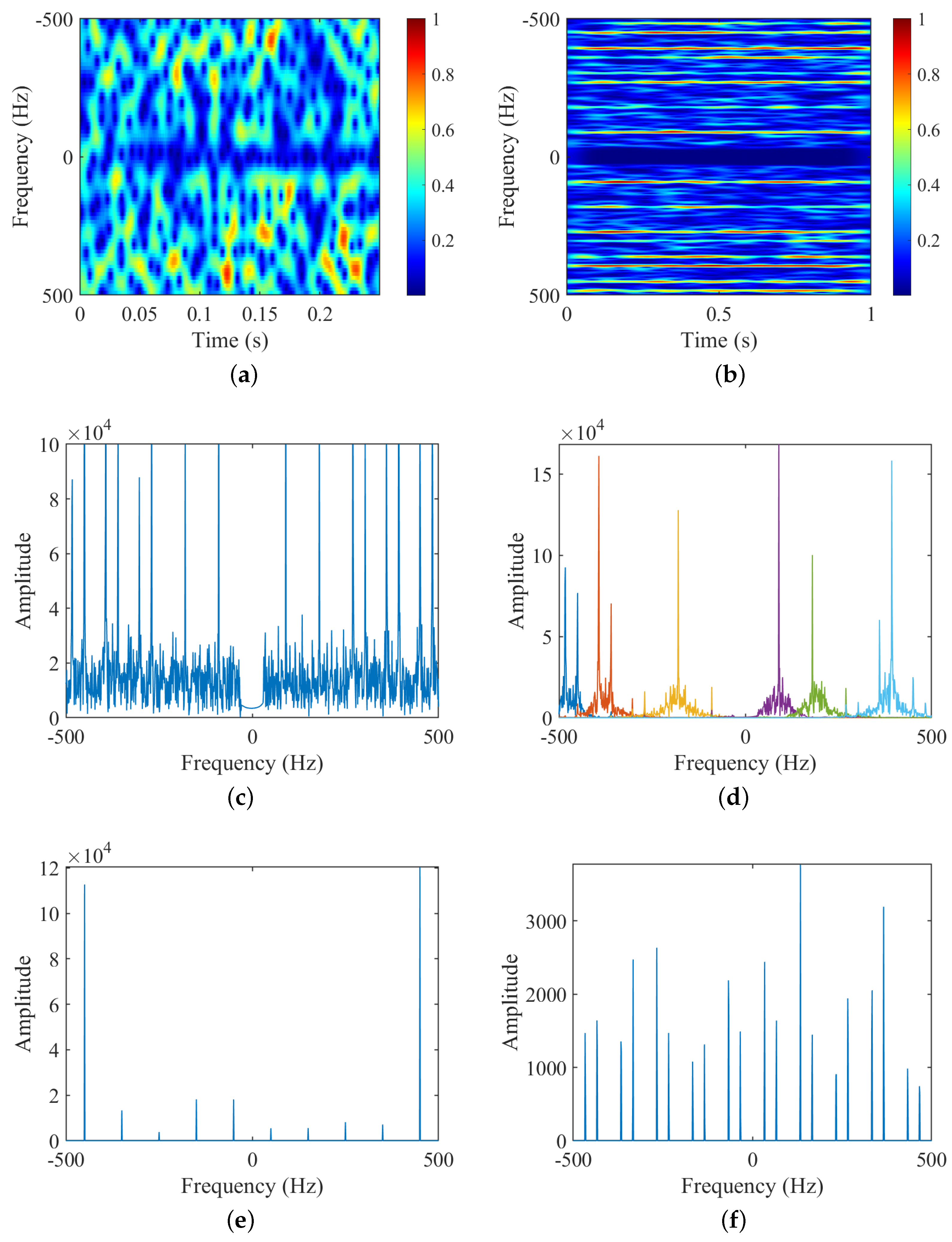
3.1.5. Experiment 4: Simulated Data with Inadequate PRF and SNR for Three-Bladed Target

Figure 7 shows the results of several time-frequency analysis methods on the simulated data of a three-bladed target with inadequate PRF at 1024 Hz and SNR at 3dB. Table 5 shows the micro-motion parameters estimation results and computational consumption of the methods. From the time-frequency figures and estimated results, we can find that:
(1)
For the number of blades N b , the STFT-based time-frequency spectrogram in Figure 7a is not capable of determining N b due to low SNR and PRF, and the HERM-based time-frequency spectrogram in Figure 7b is similarly not capable of determining N b . and finally, combined with the frequency point amplitude of the multi-blade validation function in Figure 7e,f, it can still be determined that N b is 3;
(2)
For the rotational frequency of blade f b , the ridges can be extracted from the time-frequency spectrograms of STFT in Figure 7a, but high-quality image clips need to be found. And the spectrograms of HERM, FFT, or VMD in Figure 7b, c, and d can still provide the extraction of the ridges or spectral lines to calculate the blade flashing frequency f flash clearly. The results for f b of the STFT, HERM, and FFT or VMD are 31.001 Hz, 30.036 Hz, and 30 Hz, respectively;
(3)
For the blade length r b , the maximum Doppler shift f d cannot be extracted due to the influence of low PRF and SNR. So the VMD-based AS-OMP method needs to be applied to search for the value of r b , according to the estimated r b by the three time-frequency analysis methods. As shown in Equation (21) to Equation (23), the blade length r b can be estimated as 31.616 cm, 32.316 cm, and 33.717 cm, respectively;
(4)
Comprehensively comparing the three methods, only the proposed method can completely estimate the number of blades N b , rotational frequency f b , and blade length r b without a priori information, and has the highest parameter estimation accuracy, although the operation speed is slightly slower than the STFT method.
The results shown here demonstrate the completeness, accuracy, and relative computational efficiency of micro-motion parameters extraction of the proposed method for a three-bladed target in inadequate PRF and SNR conditions.

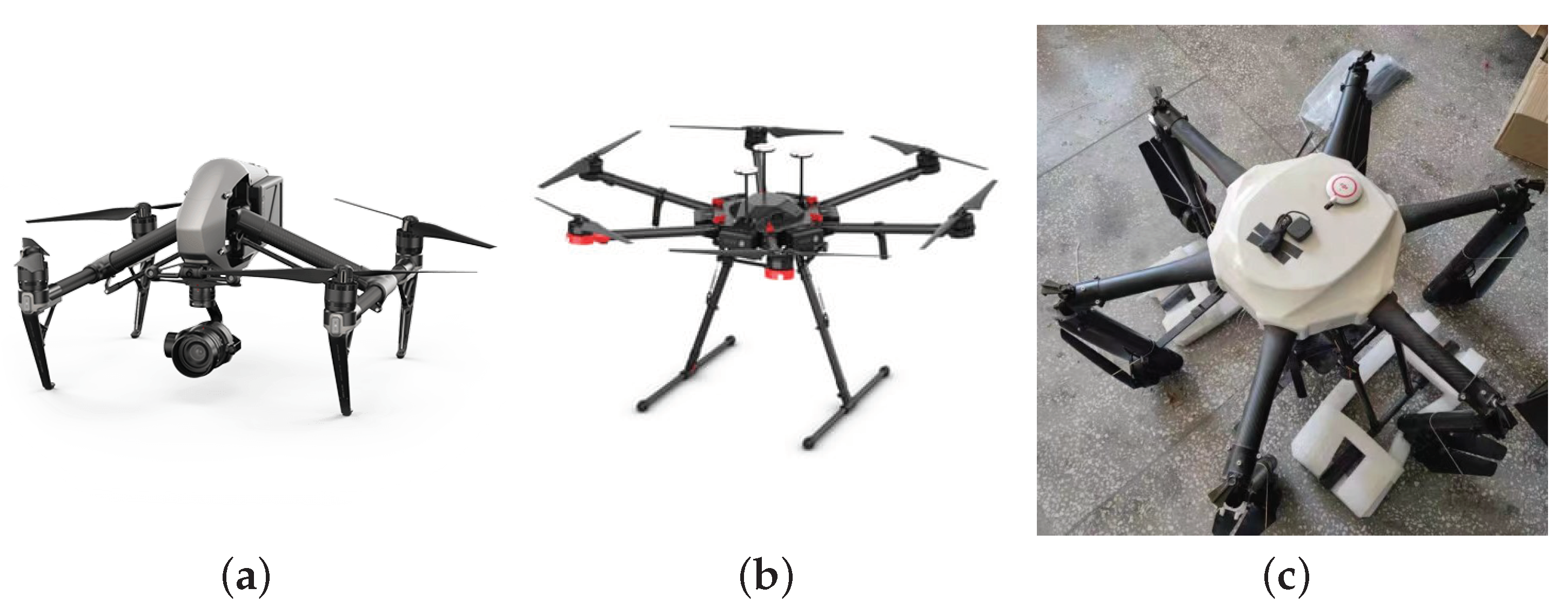
3.2. Experiments on Outdoor Scene Measured Data

3.2.1. Introduction to Outdoor Experimental Scene and Targets

Table 6 shows the main parameters of the radar signal in the outdoor scene measured experiments. The radar used to detect the DJI UAVs is a frequency modulation continuous wave (FMCW) radar with a modulation bandwidth of 100 MHz. The radar operates in the L-band with a carrier frequency of 1.5 GHz. The signal sampling frequency is 500 kHz and the pulse repetition period is 0.3 ms, which can meet the requirements of the target micro-motion parameter extraction. The targets and the radar are approximately on the same level, so the radar’s line-of-sight pitch angle is about 0 . The radar for detecting the hexacopter test UAV is a narrow-band CW radar. The radar operates in the X-band with a carrier frequency of 9.5 GHz, and the signal sampling frequency is 1 kHz, which is aliased in the spectrum and cannot meet the requirements of extracting all the micro-motion parameters of the target. The radar has a line-of-sight pitch angle of approximately 6 . 526 .
Figure 8 shows the photos, and Table 7 shows the main parameters of the multi-rotor UAVs in the outdoor scene measured experiments. Three UAVs were selected for the real-world experiments. Among them, the data of two DJI UAVs are from the open dataset of the Journal of Radar in China [35], and the download link is https://radars.ac.cn/web/data/getData?dataType=LLS-LFMCWR. The data segment used by DJI Inspire 2 is 04-2023.5.8-0.3-100-11-L (1).mat and the data segment used by DJI Matrice 600 is 05-2023.5.8-0.3-100-11-L(2).mat. Some main technical indicators of the two DJI UAVs are from the technical documents on DJI’s official website. The theoretical maximum speed of the engines used in DJI UAVs can be calculated by the product of KV and the maximum working voltage of the engines, and the revolutions per minute (RPM) will be lost by about 20 % after engines are loaded with blades. The data of the hexacopter test UAV are from the Chinese Flight Test Establishment.
The computer configuration used for the simulation experiments is as follows: 12th Gen Intel(R) Core(TM) i7-12700, 2.10 GHz, DDR4 RAM 32.0 GB, NVIDIA GeForce RTX 3070, Windows 11, MATLAB 2022a.

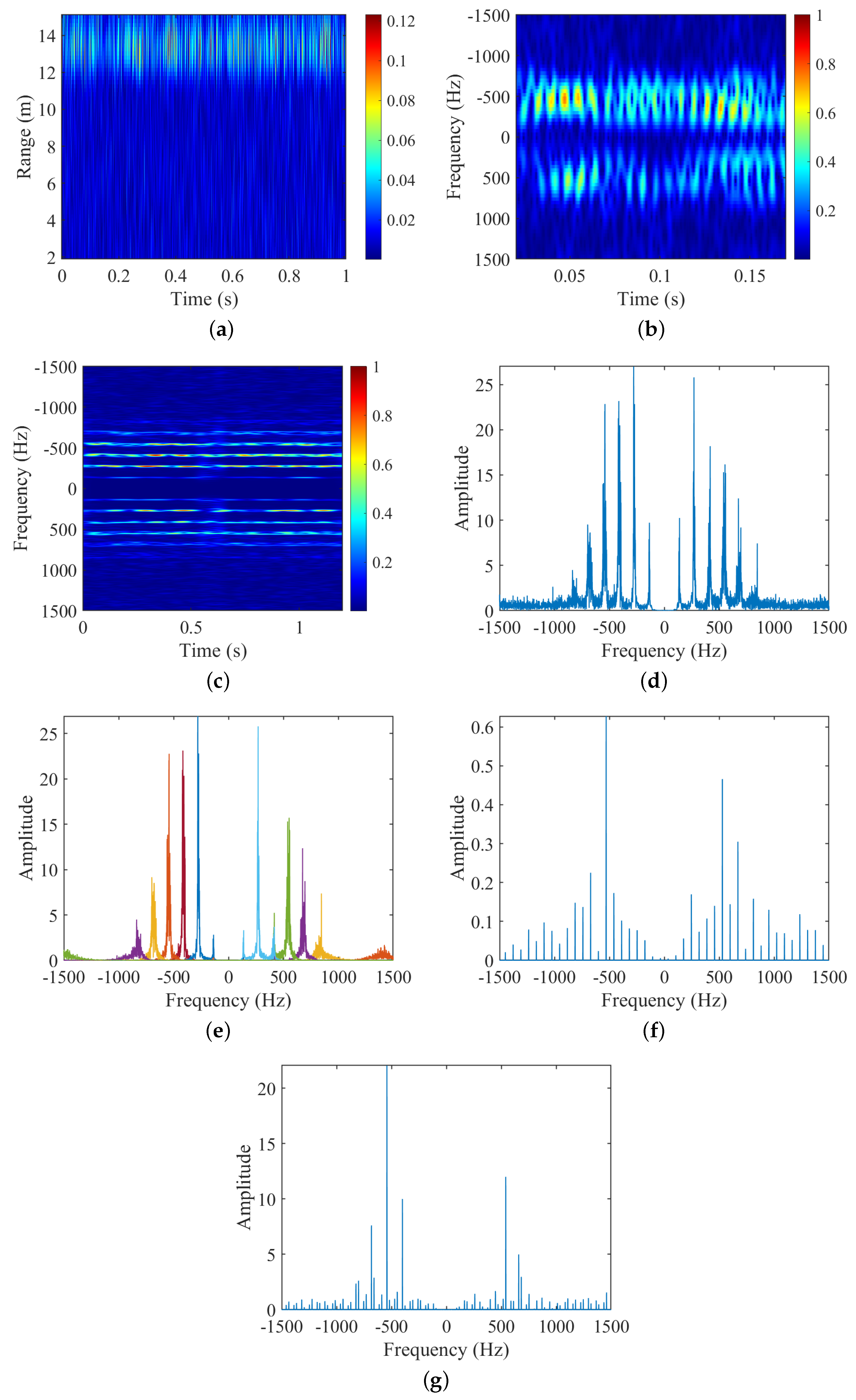
3.2.2. Experiment 5: Measured Data for DJI Inspire 2

Figure 9 shows the results of several time-frequency analysis methods on the simulated data of DJI Inspire 2. Table 8 shows the micro-motion parameters estimation results and computational consumption of the methods. From the time-frequency figures and estimated results, we can find that:
(1)
For the number of blades N b , the STFT-based time-frequency spectrogram in Figure 9b is not capable of determining N b due to the SNR and PRF of measured data, and the HERM-based time-frequency spectrogram in Figure 9c is similarly not capable of determining N b and, finally, by combining it with the frequency point amplitude of the multi-blade validation function in Figure 9f,g, it can still be determined that N b is 2;
(2)
For the rotational frequency of blade f b , the ridges can be extracted from the time-frequency spectrograms of STFT in Figure 9b, but high-quality image clips need to be found. And the spectrograms of HERM, FFT, or VMD in Figure 9c, d, and e can still provide the extraction of the ridges or spectral lines to calculate the blade flashing frequency f flash clearly. The results for f b of the STFT, HERM, and FFT or VMD are 68.653 Hz, 68.944 Hz, and 70.602 Hz, respectively;
(3)
For the blade length r b , the maximum Doppler shift f d can be extracted from the time-frequency figures of Figure 9b–d or e, and the results are 816.813 Hz, 816.017 Hz, and 841.667 Hz, respectively. So the blade length r b can be calculated through Equation (18), and the estimated results are 19.503 cm, 18.837 cm, and 18.973 cm, respectively;
(4)
Comprehensively comparing the three methods, only the proposed method can completely estimate the number of blades N b , rotational frequency f b , and blade length r b without a priori information, and has the highest parameter estimation accuracy, although the operation speed is slightly slower than that of the STFT method.
The results shown here demonstrate the completeness, accuracy, and relative computational efficiency of micro-motion parameters extraction of the proposed method for the measured data of DJI Ispire 2 in outdoor scenes.

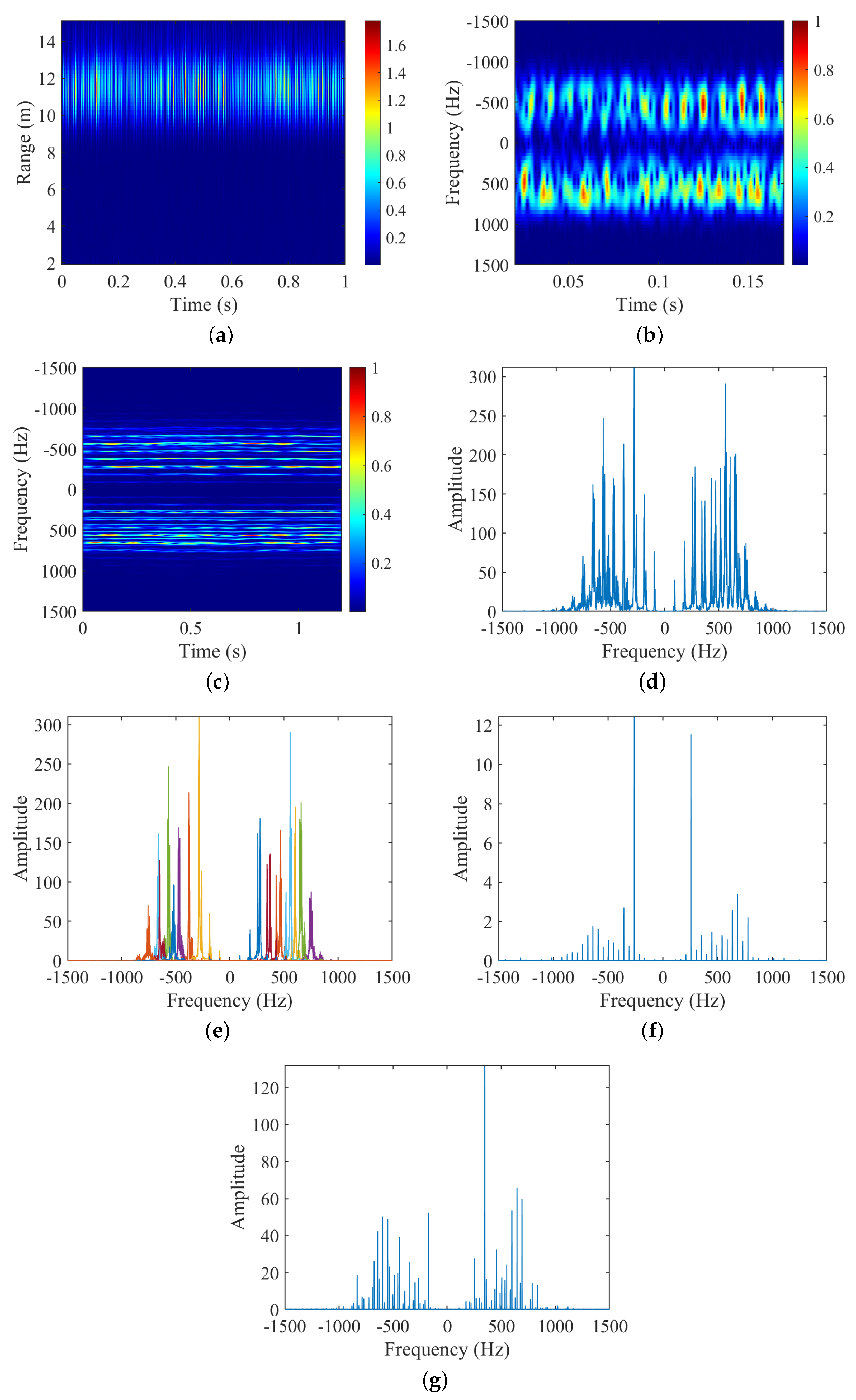
3.2.3. Experiment 6: Measured Data for DJI Matrice 600

Figure 10 shows the results of several time-frequency analysis methods on simulated data of DJI Matrice 600. Table 9 shows the micro-motion parameters estimation results and computational consumption of the methods. From the time-frequency figures and estimated results, we can find that:
(1)
For the number of blades N b , the STFT-based time-frequency spectrogram in Figure 10b is not capable of determining N b due to the SNR and PRF of measured data, and the HERM-based time-frequency spectrogram in Figure 10c is similarly not capable of determining N b . Finally, combining it with the frequency point amplitude of the multi-blade validation function in Figure 10f,g, it can still be determined that N b is 2;
(2)
For the rotational frequency of blade f b , the ridges can be extracted from the time-frequency spectrograms of STFT in Figure 10b, but high-quality image clips need to be found. And the spectrograms of HERM, FFT, or VMD in Figure 10c, d, and e can still provide the extraction of the ridges or spectral lines to calculate the blade flashing frequency f flash clearly. The results for f b of the STFT, HERM, and FFT or VMD are 48.298 Hz, 47.008 Hz, and 47.153 Hz, respectively;
(3)
For the blade length r b , the maximum Doppler shift f d can be extracted from the time-frequency figures of Figure 10b–d or e, and the results are 838.889 Hz, 761.517 Hz, and 752.197 Hz, respectively. So the blade length r b can be calculated through Equation (18), and the estimated results are 27.644 cm, 25.094 cm, and 25.413 cm, respectively;
(4)
Comprehensively comparing the three methods, only the proposed method can completely estimate the number of blades N b , rotational frequency f b , and blade length r b without a priori information, and has the highest parameter estimation accuracy, although the operation speed is slightly slower than that of the STFT method.
The results shown here demonstrate the completeness, accuracy, and relative computational efficiency of the micro-motion parameters extraction of the proposed method for the measured data of DJI Matrice 600 in outdoor scenes.

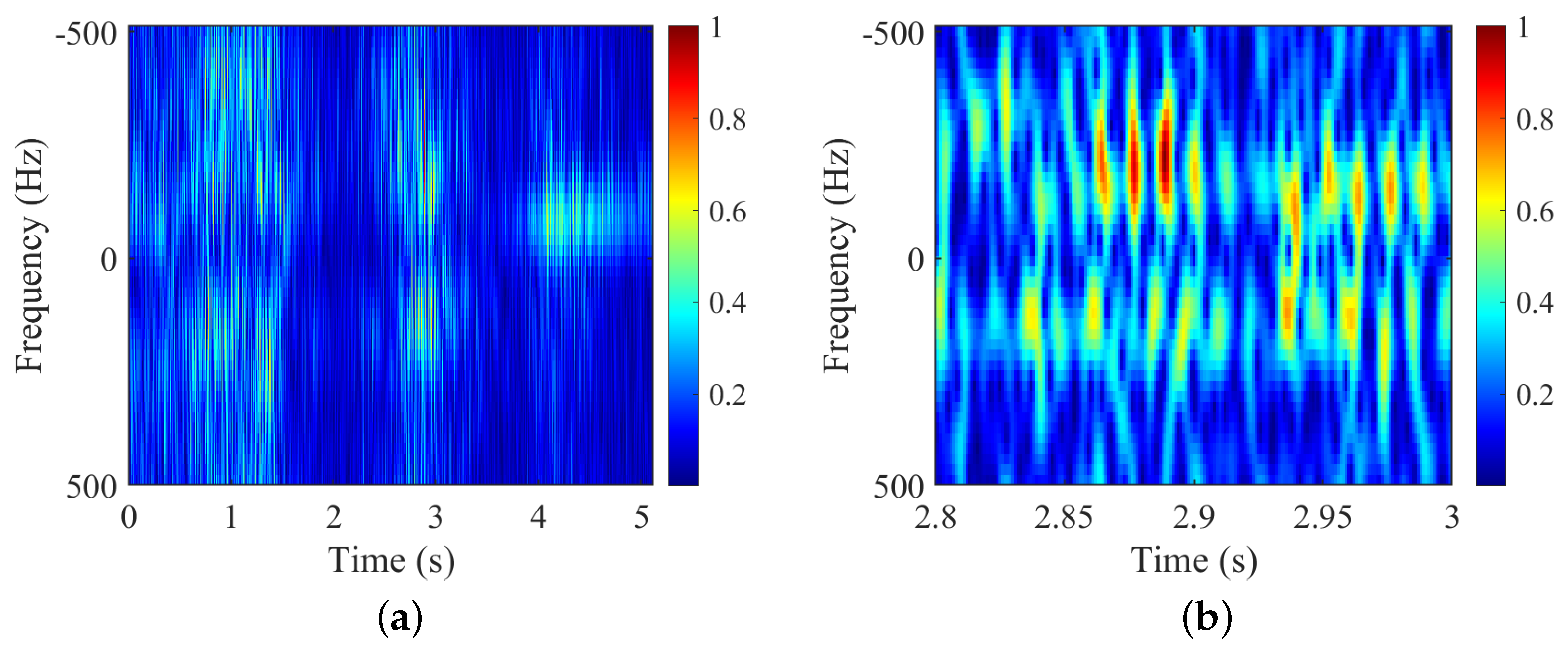
3.2.4. Experiment 7: Measured Data for Hexacopter Test UAV

Figure 11 shows the results of several time-frequency analysis methods on the simulated data of the hexacopter. Table 10 shows the micro-motion parameters estimation results and computational consumption of the methods. From the time-frequency figures and estimated results, we can find that:
(1)
For the number of blades N b , the STFT-based time-frequency spectrogram in Figure 11b is not capable of determining N b due to the SNR and PRF of measured data, and the HERM-based time-frequency spectrogram in Figure 11c is similarly not capable of determining N b . Finally, combined with the frequency point amplitude of the multi-blade validation function in Figure 11f,g, it can still be determined that N b is 2;
(2)
For the rotational frequency of blade f b , the ridges can be extracted from the time-frequency spectrograms of STFT in Figure 11b, but high-quality image clips need to be found. And the spectrograms of HERM, FFT, or VMD in Figure 11c, d, and e can still provide the extraction of the ridges or spectral lines to calculate the blade flashing frequency f flash clearly. The results for f b of the STFT, HERM, and FFT or VMD are 41.667 Hz, 41.294 Hz, and 41.242 Hz, respectively;
(3)
For the blade length r b , the maximum Doppler shift f d cannot be extracted due to the influence of the low PRF and SNR of the measured data. So, the VMD-based AS-OMP method needs to be applied to search for the value of r b , according to the estimated r b by the three time-frequency analysis methods. As shown in Equation (21) to Equation (23), the blade length r b can be estimated as 31.436 cm, 32.876 cm, and 34.128 cm, respectively;
(4)
Comprehensively comparing the three methods, only the proposed method can completely estimate the number of blades N b , rotational frequency f b , and blade length r b without a priori information, and has the highest parameter estimation accuracy, although the operation speed is slightly slower than that of the STFT method.
The results shown here demonstrate the completeness, accuracy, and relative computational efficiency of micro-motion parameters extraction of the proposed method for the measured data of the hexacopter UAV in outdoor scenes.

4. Discussion

The method proposed in this paper provides a robust estimation of the number of blades, rotational frequency, and blade length for multi-rotor targets, which provides support for the monitoring and identification of LLS targets. However, several problems and shortcomings remain that need further discussion and future in-depth research.
(1)
Due to the good portability of the blade number estimation methods proposed in this paper, they are compared only for the widely used STFT and HERM, and the underlying time-frequency analysis methods are compared. More efficient methods for estimating blade rotation frequency, blade length, and initial phase etc. can be combined with the proposed method in this paper to improve the micro-motion parameters estimation capability;
(2)
The detection of multi-rotor targets often encounters low radar PRF and SNR that are insufficient to efficiently estimate the target Doppler maximum frequency shift, which is addressed in this paper by jointly applying a VMD-based AS-OMP method. However, the frequency search range of VMD needs to be set appropriately. The setting of AS coefficients and complex time-consuming calculations are required to improve the estimation performance of the method, and more efficient and accurate joint estimation of blade lengths needs to be investigated in the future;
(3)
The proposed method has no restriction on the number of blades for multi-rotor targets, but, limited by the available aircraft types and measured data, this paper is only validated on simulation data for two-bladed and three-bladed targets and measured data for two-bladed targets. With the rapid development of multi-rotor aircraft, it is believed that the proposed method will have more potential for future applications.

5. Conclusions

In this article, we proposed a micro-motion parameters estimation method for multi-rotor targets without a prior blade number that adapts to complex, noisy scenarios with low PRF and insufficient SNR. After estimating the flashing frequency, We construct a validation function on the basis of spectral analysis to judge the number of blades, and then the rotational frequency is estimated. The length of the blades is calculated by estimating the maximum Doppler shift. Moreover, the proposed method jointly applied the VMD-based AS-OMP method to estimate the blade length in the situation of inadequate PRF or sampling frequency and a harsh noisy environment with insufficient SNR. Compared to the STFT and HERM-based micro-motion parameter estimation method, the proposed method also has a comparative advantage in terms of computational efficiency with the highest accuracy of all micro-motion parameter estimation. The performance of the proposed method has been validated in experiments conducted on three types of UAVs from different sources, ensuring it has good robustness and wide application prospects.

Author Contributions

Conceptualization, J.R. and Y.L.; methodology, J.R.; software, J.R.; validation, J.R., Y.L. and H.W.; formal analysis, Y.L.; investigation, K.-m.L. and D.Z.; resources, D.Z.; data curation, D.Z.; writing—original draft preparation, J.R.; writing—review and editing, J.R., H.W., Y.L. and J.L.; visualization, J.L.; supervision, Y.L., J.L. and K.-m.L.; project administration, Y.L., J.L. and K.-m.L.; funding acquisition, Y.L. and J.L. All authors have read and agreed to the published version of the manuscript.

Funding

This work is supported in part by the National Nature Science Foundation of China under Grant 62371468, China Postdoctoral Science Foundation under Grant No. 2021MD703951, the Youth Talent Lifting Project of the China Association for Science and Technology No. 2021-JCJQ-QT-018 and the Youth Innovation Team of Shaanxi Universities.

Data Availability Statement

The data presented in this study are available in article.

Acknowledgments

We are very grateful to Editorial Board of the Journal of Radars and the Marine Target Detection Research Group of Naval Aviation University in China for providing the multiband FMCW radar LSS-target detection dataset (LSS-FMCWR-1.0) and the pre-proposing code for measured data in CHEN Xiaolong, Yuan Wang, Du Xiaolin, et al. Multiband FMCW radar LSS-target detectiondataset (LSS-FMCWR-1.0) and high-resolution micromotion feature extraction method[J]. Journal of Radars, in press. https://doi.org/10.12000/JR23142 [35]. We are also very grateful to the Chinese Flight Test Establishment for providing the measured data of the hexacopter test UAV.

Conflicts of Interest

The authors declare no conflict of interest.

References

  1. Colomina, I.; Molina, P. Unmanned aerial systems for photogrammetry and remote sensing: A review. ISPRS J. Photogramm. Remote. Sens. 2014, 92, 79–97. [Google Scholar] [CrossRef]
  2. Zhang, Q.; Zeng, Y.; He, Y.; Luo, Y. Avian detection and identification with high-resolution radar. In Proceedings of the 2008 IEEE Radar Conference, Rome, Italy, 26–30 May 2008; pp. 1–6. [Google Scholar] [CrossRef]
  3. Hanif, A.; Muaz, M.; Hasan, A.; Adeel, M. Micro-Doppler Based Target Recognition With Radars: A Review. IEEE Sens. J. 2022, 22, 294–2961. [Google Scholar] [CrossRef]
  4. Zhang, S.; Liu, Y.; Li, X. Micro-Doppler Effects Removed Sparse Aperture ISAR Imaging via Low-Rank and Double Sparsity Constrained ADMM and Linearized ADMM. IEEE Trans. Image Process. 2021, 30, 4678–4690. [Google Scholar] [CrossRef]
  5. Chen, V.C.; Li, F.; Ho, S.-S.; Wechsler, H. Micro-Doppler effect in radar: Phenomenon, model, and simulation study. IEEE Trans. Aerosp. Electron. Syst. 2006, 42, 2–21. [Google Scholar] [CrossRef]
  6. Qun, Z.; Jian, H.; Ying, L.; Yijun, C. Research progresses in radar feature extraction, imaging, and recognition of target with micro-motions. J. Radars 2018, 7, 531–547. [Google Scholar] [CrossRef]
  7. Chen, X.; Chen, W.; Rao, Y.; Huang, Y.; Guan, J.; Dong, Y. Progress and prospects of radar target detection and recognition technology for flying birds and unmanned aerial vehicles. J. Radars 2020, 9, 803–827. [Google Scholar] [CrossRef]
  8. Zhang, Q.; Yeo, T.S.; Tan, H.S.; Luo, Y. Imaging of a Moving Target With Rotating Parts Based on the Hough Transform. IEEE Trans. Geosci. Remote. Sens. 2006, 46, 291–299. [Google Scholar] [CrossRef]
  9. Luo, Y.; Zhang, Q.; Qiu, C.W.; Liang, X.J.; Li, K.M. Micro-Doppler Effect Analysis and Feature Extraction in ISAR Imaging with Stepped-Frequency Chirp Signals. IEEE Trans. Geosci. Remote. Sens. 2010, 48, 2087–2098. [Google Scholar] [CrossRef]
  10. Bai, X.; Bai, X.; Xing, M.; Zhou, F.; Bao, Z. High-Resolution Three-Dimensional Imaging of Spinning Space Debris. IEEE Trans. Geosci. Remote. Sens. 2009, 47, 2352–2362. [Google Scholar] [CrossRef]
  11. Bai, X.; Bai, X.; Zhou, F.; Xing, M.; Bao, Z. High Resolution ISAR Imaging of Targets with Rotating Parts. IEEE Trans. Aerosp. Electron. Syst. 2011, 47, 2530–2543. [Google Scholar] [CrossRef]
  12. Thayaparan, T.; Stanković, L.; Djurović, I. Micro-Doppler-based target detection and feature extraction in indoor and outdoor environments. J. Frankl. Inst. 2008, 345, 700–722. [Google Scholar] [CrossRef]
  13. Suresh, P.; Thayaparan, T.; Obulesu, T.; Venkataramaniah, K. Extracting Micro-Doppler Radar Signatures From Rotating Targets Using Fourier–Bessel Transform and Time–Frequency Analysis. IEEE Trans. Geosci. Remote. Sens. 2014, 52, 3204–3210. [Google Scholar] [CrossRef]
  14. Zhao, Y.; Su, Y. Cyclostationary Phase Analysis on Micro-Doppler Parameters for Radar-Based Small UAVs Detection. IEEE Trans. Instrum. Meas. 2018, 67, 2048–2057. [Google Scholar] [CrossRef]
  15. Zhao, Y.; Zhao, Y.; Zhao, Y.; Su, Y.; Su, Y. Sparse Recovery on Intrinsic Mode Functions for the Micro-Doppler Parameters Estimation of Small UAVs. IEEE Trans. Geosci. Remote. Sens. 2019, 57, 7182–7193. [Google Scholar] [CrossRef]
  16. Zhao, Y.; Su, Y. The Extraction of Micro-Doppler Signal With EMD Algorithm for Radar-Based Small UAVs’ Detection. IEEE Trans. Instrum. Meas. 2020, 69, 929–940. [Google Scholar] [CrossRef]
  17. Bączyk, M.K.; Samczyński, P.; Kulpa, K.; Misiurewicz, J. Micro-Doppler signatures of helicopters in multistatic passive radars. IET Radar Sonar Navig. 2015, 9, 1276–1283. [Google Scholar] [CrossRef]
  18. Rahman, S.; Robertson, D.A. Millimeter-wave micro-Doppler measurements of small UAVs. Proc. SPIE 2017, 10188, 101880T. [Google Scholar] [CrossRef]
  19. Singh, A.K.; Kim, Y.-H. Automatic Measurement of Blade Length and Rotation Rate of Drone Using W-Band Micro-Doppler Radar. IEEE Sensors J. 2018, 18, 1895–1902. [Google Scholar] [CrossRef]
  20. Huang, A.; Sevigny, P.; Balaji, B.; Rajan, S. Fundamental Frequency Estimation of HERM Lines of Drones. In Proceedings of the 2020 IEEE International Radar Conference (RADAR), Washington, DC, USA, 28–30 April 2020; pp. 1013–1018. [Google Scholar] [CrossRef]
  21. Gannon, Z.E.; Gannon, Z.; Tahmoush, D.; Tahmoush, D. Measuring UAV Propeller Length using Micro-Doppler Signatures. In Proceedings of the 2020 IEEE International Radar Conference (RADAR), Washington, DC, USA, 28–30 April 2020. [Google Scholar] [CrossRef]
  22. Fang, X.; Xiao, G. Rotor Blades Micro-Doppler Feature Analysis and Extraction of Small Unmanned Rotorcraft. IEEE Sensors J. 2021, 21, 3592–3601. [Google Scholar] [CrossRef]
  23. Kang, K.-B.; Choi, J.-H.; Cho, B.-L.; Lee, J.-S.; Kim, K.-T. Analysis of Micro-Doppler Signatures of Small UAVs Based on Doppler Spectrum. IEEE Trans. Aerosp. Electron. Syst. 2021, 57, 3252–3267. [Google Scholar] [CrossRef]
  24. Mao, T.; Li, Z.; Zhu, K.; Zhang, Y.; Sun, H. Radar backscattering modelling and micro-motion parameter estimation method for quadcopter. IET Radar Sonar Navig. 2022, 16, 161–169. [Google Scholar] [CrossRef]
  25. Ciattaglia, G.; Iadarola, G.; Senigagliesi, L.; Spinsante, S.; Gambi, E. UAV Propeller Rotational Speed Measurement through FMCW Radars. Remote. Sens. 2023, 15, 270. [Google Scholar] [CrossRef]
  26. Bennett, C.; Harman, S.; Petrunin, I. Realistic Simulation of Drone Micro-Doppler Signatures. In Proceedings of the 2021 18th European Radar Conference (EuRAD), London, UK, 5–7 April 2022; pp. 114–117. [Google Scholar] [CrossRef]
  27. Oh, B.S.; Guo, X.; Lin, Z. A UAV classification system based on FMCW radar micro-Doppler signature analysis. Expert Syst. Appl. 2019, 132, 239–255. [Google Scholar] [CrossRef]
  28. Chen, X.; Zhang, H.; Song, J.; Guan, J.; Li, J.; He, Z. Micro-Motion Classification of Flying Bird and Rotor Drones via Data Augmentation and Modified Multi-Scale CNN. Remote. Sens. 2022, 14, 1107. [Google Scholar] [CrossRef]
  29. Tian, X.; Bai, X.; Xue, R.; Qin, R.; Zhou, F. Fusion Recognition of Space Targets With Micromotion. IEEE Trans. Aerosp. Electron. Syst. 2022, 58, 3116–3125. [Google Scholar] [CrossRef]
  30. Dai, T.; Xu, S.; Tian, B.; Hu, J.; Zhang, Y.; Chen, Z. Extraction of Micro-Doppler Feature Using LMD Algorithm Combined Supplement Feature for UAVs and Birds Classification. Remote. Sens. 2022, 14, 2196. [Google Scholar] [CrossRef]
  31. Wang, H.; Zhang, Q.; Luo, Y.; Kang, L.; Lu, X.F. Obtaining TFR From Incomplete and Phase-Corrupted m-D Signal in Real Time. IEEE Geosci. Remote. Sens. Lett. 2022, 19, 1–5. [Google Scholar] [CrossRef]
  32. Dragomiretskiy, K.; Zosso, D. Variational Mode Decomposition. IEEE Trans. Signal Process. 2014, 62, 531–544. [Google Scholar] [CrossRef]
  33. Ying, L.; Qun, Z.; Guo-Zheng, W.; Hua, G.; You-Qing, B. Micro-motion Signature Extraction Method for Wideband Radar Based on Complex Image OMP Decomposition. J. Radars 2012, 1, 361–369. [Google Scholar] [CrossRef]
  34. Luo, Y.; Zhang, Q.; Qiu, C.; Li, S.; Yeo, T.S. Micro-Doppler feature extraction for wideband imaging radar based on complex image orthogonal matching pursuit decomposition. IET Radar Sonar Navig. 2013, 7, 914–924. [Google Scholar] [CrossRef]
  35. Xiaolong, C.H.; Wang, Y.; Xiaolin, D.; Gang, Y.; Xiaoyang, H.; Jian, G.; Xinghai, W. Multiband FMCW radar LSS-target detectiondataset (LSS-FMCWR-1.0) and high-resolution micromotion feature extraction method. J. Radars 2023, in press. [Google Scholar] [CrossRef]
Figure 1. Schematic of a multi-rotor target detection scenario.
Remotesensing 16 01409 g001
Figure 2. Schematic diagram of fluctuation characteristics for G ( f ) . (a) G 2 ( f ) ; (b) G 3 ( f ) .
Remotesensing 16 01409 g002
Figure 3. Flow chart of the proposed micro-motion parameters extraction algorithm.
Remotesensing 16 01409 g003
Figure 4. Experiment 1: Simulated data with adequate PRF and SNR for two-bladed target. (a) STFT; (b) HERM; (c) FFT; (d) VMD; (e) Frequency points of two-bladed validation function; (f) Frequency points of three-bladed validation function.
Remotesensing 16 01409 g004
Figure 5. Experiment 2: Simulated data with inadequate PRF and SNR for two-bladed target. (a) STFT; (b) HERM; (c) FFT; (d) VMD; (e) frequency points of two-blade validation function; (f) frequency points of three-blade validation function.
Remotesensing 16 01409 g005
Figure 6. Experiment 3: Simulated data with adequate PRF and SNR for three-bladed target. (a) STFT; (b) HERM; (c) FFT; (d) VMD; (e) frequency points of two-blade validation function; (f) frequency points of three-blade validation function.
Remotesensing 16 01409 g006aRemotesensing 16 01409 g006b
Figure 7. Experiment 4: Simulated data with inadequate PRF and SNR for three-bladed target. (a) STFT; (b) HERM; (c) FFT; (d) VMD; (e) frequency points of two-bladed validation function; (f) frequency points of three-bladed validation function.
Remotesensing 16 01409 g007
Figure 8. Photos of measured experimental multi-rotor UAVs. (a) DJI Inspire2; (b) DJI Matrice 600; (c) Hexacopter Test UAV.
Remotesensing 16 01409 g008
Figure 9. Experiment 5: Measured data for DJI Inspire 2. (a) Range-period chart; (b) STFT; (c) HERM; (d) FFT; (e) VMD; (f) frequency points of two-bladed validation function; (g) frequency points of three-bladed validation function.
Remotesensing 16 01409 g009
Figure 10. Experiment 6: Measured data for DJI Matrice 600. (a) Range-period chart; (b) STFT; (c) HERM; (d) FFT; (e) VMD; (f) frequency points of two-bladed validation function; (g) frequency points of three-bladed validation function.
Remotesensing 16 01409 g010
Figure 11. Experiment 7: Measured data for hexacopter test UAV. (a) Overview of the data; (b) STFT; (c) HERM; (d) FFT; (e) VMD; (f) frequency points of two-blade validation function; (g) frequency points of three-blade validation function.
Remotesensing 16 01409 g011aRemotesensing 16 01409 g011b
Table 1. Simulation parameters for radar signals and multi-rotor targets.
ParametersValue
Radar signalCW
Carrier frequency1.8 GHz
Radar line-of-sight pitch angle 0
Adequate/Inadequate PRF4096/1024 Hz
Adequate/Inadequate SNR10/3 dB
Distance of target7645 m
Number of rotors4
Number of blades2 or 3
Length of blades35 cm
Rotational frequency30 Hz
Table 2. Experiment 1: Simulated data with adequate PRF and SNR for two-bladed target.
T-F
Analysis
Method
Number
of
Blade
Rotational
Frequency
(Hz)
Maximum
Doppler Shift
(Hz)
Blade Length (cm)Running
Time (s)
Theoretical
Value
Estimated
Value
Relative
Error
STFT2 N * 29.891819.2003536.3503.86%2.108
HERM-29.979781.0223534.5501.57%3.265
Our Method230790.0003534.9300.20%2.566
Table 3. Experiment 2: Simulated data with inadequate PRF and SNR for two-bladed target.
T-F
Analysis
Method
Number
of
Blade
Rotational Speed (Hz)Blade Length (cm)Running
Time (s)
Theoretical
Value
Estimated
Value
Theoretical
Value
Estimated
Value
Relative
Error
STFT-3033.0033532.3267.64%26.398
HERM-3030.2513533.9172.98%26.719
Our Method230303534.0172.81%27.129
Table 4. Experiment 3: Simulated data with adequate PRF and SNR for three-bladed target.
T-F
Analysis
Method
Number
of
Blade
Rotational
Frequency
(Hz)
Maximum
Doppler Shift
(Hz)
Blade Length (cm)Running
Time (s)
Theoretical
Value
Estimated
Value
Relative
Error
STFT2 N * + 130.560771.8273533.5004.29%2.944
HERM-29.178722.1433532.8206.23%3.628
Our Method330810.0003535.8102.31%3.999
Table 5. Experiment 4: Simulated data with inadequate PRF and SNR for three-bladed target.
T-F
Analysis
Method
Number
of
Blade
Rotational Speed (Hz)Blade Length (cm)Running
Time (s)
Theoretical
Value
Estimated
Value
Theoretical
Value
Estimated
Value
Relative
Error
STFT-3031.0013531.6169.67%27.724
HERM-3030.0363532.3167.67%28.077
Our Method330303533.7173.67%28.583
Table 6. Main technical indicators of the radars.
ParametersDJI UAVsHexacopter Test UAV
Radar signalFMCWCW
Radar bandL bandX band
Carrier frequency1.5 GHz9.5 GHz
Modulation bandwidth100 MHznarrow-band
Modulation period0.3 ms-
Sampling frequency/PRF500 kHz1 kHz
Radar line-of-sight pitch angle6.526°
Table 7. Main technical indicators of the UAVs.
Type of UAVsNumber of Rotors/BladesDistance of Target (m)KV of Electric Engine (rpm/V)Maximum Working Voltage (V)Maximum Rotational Speed (r/min)Length of Blades (cm)
DJI Inspire 2 *4/213.246022.810,488 **19
DJI Matrice 600 *6/211.513052.26786 **26.5
Hexacopter Test UAV6/27481--2000–3000 (hovering)35.5
* Data from technical documents on DJI’s official website. ** RPM will be lost by about 20% after engines being loaded with blades.
Table 8. Experiment 5: Measured data for DJI Inspire 2.
T-F
Analysis
Method
Number
of
Blade
Rotational
Frequency
(Hz)
Maximum
Doppler Shift
(Hz)
Blade Length (cm)Running
Time (s)
Theoretical
Value
Estimated
Value
Relative
Error
STFT-66.653816.8131919.5042.653%1.475
HERM-68.944816.0171918.8370.858%3.732
Our Method270.602841.6671918.9730.142%1.957
Table 9. Experiment 6: Measured data for DJI Matrice 600.
T-F
Analysis
Method
Number
of
Blade
Rotational
Frequency
(Hz)
Maximum
Doppler Shift
(Hz)
Blade Length (cm)Running
Time (s)
Theoretical
Value
Estimated
Value
Relative
Error
STFT-48.298838.88926.527.6444.317%1.063
HERM-47.008761.51726.525.0945.306%3.251
Our Method247.153752.19726.525.4134.102%1.586
Table 10. Experiment 7: Measured data for hexacopter test UAV.
T-F
Analysis
Method
Number
of
Blade
Rotational
Frequency
(Hz)
Maximum
Doppler Shift
(Hz)
Blade Length (cm)Running
Time (s)
Theoretical
Value
Estimated
Value
Relative
Error
STFT-41.667-35.531.43611.448%32.360
HERM-41.294-35.532.8767.392%36.005
Our Method241.242-35.534.1283.865%34.023
Disclaimer/Publisher’s Note: The statements, opinions and data contained in all publications are solely those of the individual author(s) and contributor(s) and not of MDPI and/or the editor(s). MDPI and/or the editor(s) disclaim responsibility for any injury to people or property resulting from any ideas, methods, instructions or products referred to in the content.

