Article

Real-Time Compensation for Unknown Image Displacement and Rotation in Infrared Multispectral Camera Push-Broom Imaging

1
Hangzhou Institute for Advanced Study, University of Chinese Academy of Sciences, Hangzhou 310024, China
2
University of Chinese Academy of Sciences, Beijing 100049, China
3
Key Laboratory of Space Active Opto-Electronics Technology, Shanghai Institute of Technical Physics, Chinese Academy of Sciences, Shanghai 200083, China
*
Author to whom correspondence should be addressed.
These authors contributed equally to this work.
Remote Sens. 2025, 17(7), 1113; https://doi.org/10.3390/rs17071113
Submission received: 20 January 2025 / Revised: 17 March 2025 / Accepted: 18 March 2025 / Published: 21 March 2025
(This article belongs to the Section Remote Sensing Image Processing)

Abstract

:
Digital time-delay integration (TDI) enhances the signal-to-noise ratio (SNR) in infrared (IR) imaging, but its effectiveness in push-broom scanning is contingent upon maintaining a stable image shift velocity. Unpredictable image shifts and rotations, caused by carrier or scene movement, can affect the imaging process. This paper proposes an advanced technical approach for infrared multispectral TDI imaging. This methodology concurrently estimates the image shift and rotation between frames by utilizing a high-resolution visible camera aligned parallel to the optical axis of the IR camera. Subsequently, parameter prediction is conducted using the Kalman model, and real-time compensation is achieved by dynamically adjusting the infrared TDI integration unit based on the predicted parameters. Simulation and experimental results demonstrate that the proposed algorithm enhances the BRISQUE score of the TDI images by 21.37%, thereby validating its efficacy in push-scan imaging systems characterized by velocity-height ratios instability and varying camera attitudes. This research constitutes a significant contribution to the advancement of high-precision real-time compensation for image shift and rotation in infrared remote sensing and industrial inspection applications.

1. Introduction

Uncooled infrared multispectral technology has emerged as a crucial innovation in various applications, including gas monitoring, fire detection, unmanned aerial vehicle (UAV) operations, and remote sensing surveillance, owing to its versatility across multiple environments and cost-effectiveness. In contrast to cooled infrared detectors, uncooled infrared detectors lack a temperature control device in the focal plane, resulting in reduced sensitivity compared to their cooled counterpart. Push-broom imaging is an advanced method for acquiring high-resolution images, widely used in environmental and resource monitoring, urban management, and security systems [1]. The application of time-delayed integration (TDI) methodology offers significant improvements in the signal-to-noise ratio and sensitivity of uncooled infrared detector imagery. This is achieved through the repeated sampling of identical scenes utilizing various pixels, wherein the velocity-to-height ratios are carefully matched [2]. However, the effectiveness of TDI relies on the stability and accuracy of this ratio; if it is mismatched, the corresponding spatial elements in the integration units become inconsistent, leading to image blurring [3]. An unstable velocity-height ratio leads to jitter-induced image shifts that severely degrade the image quality [4]. Furthermore, alterations in camera orientation during the imaging process can result in image shift errors and distortion [5,6]. Consequently, the identification of image shifts, self-supervision of camera orientation, and real-time compensation for image shifts are critical components in ensuring high-quality imaging outcomes.
Existing known image-shift compensation techniques primarily include mechanical, optical, and electronic methods. Mechanical image-shift compensation involves detecting device jitter using gyroscopes and accelerometers and compensating for the shift by adjusting the sensor and optical component positions mechanically. For instance, Yang et al. [7] designed a triaxial inertial stabilization platform based on a cantilever beam structure for image shift compensation. Optical image-shift compensation involves the adjustment of optical elements within the lens or lens assembly. Wang et al. [8] utilized a fast-steering mirror to estimate and compensate for disturbances in real-time. Li et al. [9] addressed drift angles in high-resolution, wide-area space cameras by adjusting their focal plane position. Some researchers have also explored the combination of optical and mechanical compensation methods [10]. Sun et al. proposed a compensation approach that utilizes a two-dimensional fast steering mirror (FSM) to correct image motion, and further enhances the compensation by employing a piezoelectric ceramic (PZT) rotating detector to address residual image motion [11]. Electronic image shift compensation involves (i) digital signal processing techniques to adjust the sensor readout mode in real time or (ii) applying digital correction during the image processing phase [12]. Zhang et al. [13] combined a coordinate transformation model with low-dimensional attitude maneuvering and TDICCD line frequency matching for image shift compensation. However, compared to electronic methods, both mechanical and optical image shift compensation require complex control equipment, increasing the overall size and cost of the system.
In high dynamic range imaging scenarios where image shift and rotation need to be identified, the simultaneous changes in object velocity and distance impose high demands for the accurate real-time performance of traditional attitude and orbit control systems [5]. Moreover, in infrared (IR) imaging scenarios, it is often necessary to use a visible camera for background image registration [6].
In this study, we employed a high-resolution visible light camera, aligned parallelly to the optical axis of the IR camera, to calculate the image shift velocity and rotation through image-matching techniques. The high-resolution visible camera enables the calculation of highly precise image shift and rotation parameters, which correspond to sub-pixel accuracy in the infrared camera. We then used a Kalman model to forecast these attributes and map them to the IR camera using affine transformations, allowing real-time correction of its TDI unit. By incorporating a Kalman model, the proposed method effectively mitigates the latency in the calculated image shift and rotation parameters, enabling precise and real-time compensation.
The advantage of the proposed method lies in its ability to achieve sub-pixel accuracy real-time TDI compensation for image shift and rotation introduced during the push-broom process, without relying on external hardware compensation devices. By establishing an affine transformation relationship between dual-mode sensors with parallel optical axes, the method enables the generation of high-quality TDI images across multiple spectral channels. This allows uncooled infrared multispectral cameras to autonomously identify the current camera state during push-broom imaging and perform real-time compensation for image shift and rotation.
Section 2 introduces the image shift model, elucidating the relationship between image shift and velocity-height ratio matching. It delineates the operational principle and hardware configuration of the off-chip digital domain TDI and examines the hardware requirements for compensating image shifts in IR imaging utilizing high-resolution visible light cameras. The methodology to compute rotational and translational disparities between consecutive frames from a visible light camera employing feature point correspondence techniques is established. The utilization of a Kalman filter to predict cumulative image rotation, vertical image shift, and horizontal image shift velocity, and to project this information onto the infrared camera image plane, is demonstrated. The real-time correction of the IR camera integration unit compensation model utilizing predicted image shift and rotation information is also addressed. Section 3 describes experiments evaluating the proposed algorithm in actual imaging, focusing on the impact of image shift and rotation on TDI images and the enhanced TDI image quality achieved through the real-time compensation algorithm. Section 4 summarizes the principal findings and delineates future research directions in image shift compensation techniques.

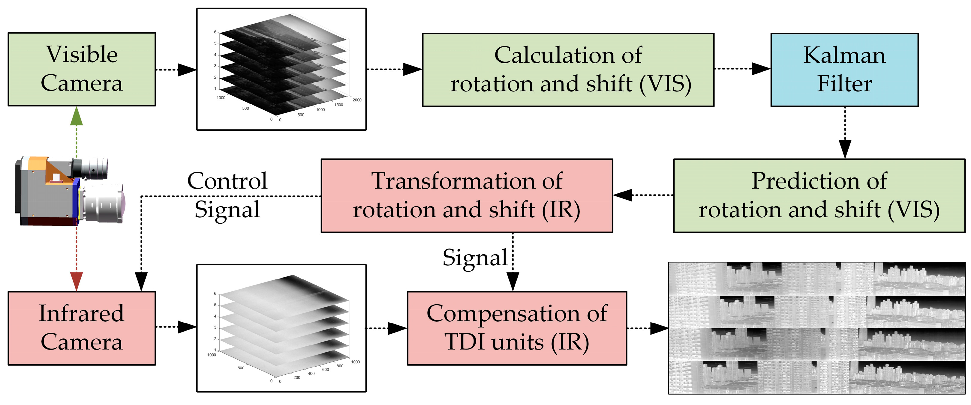
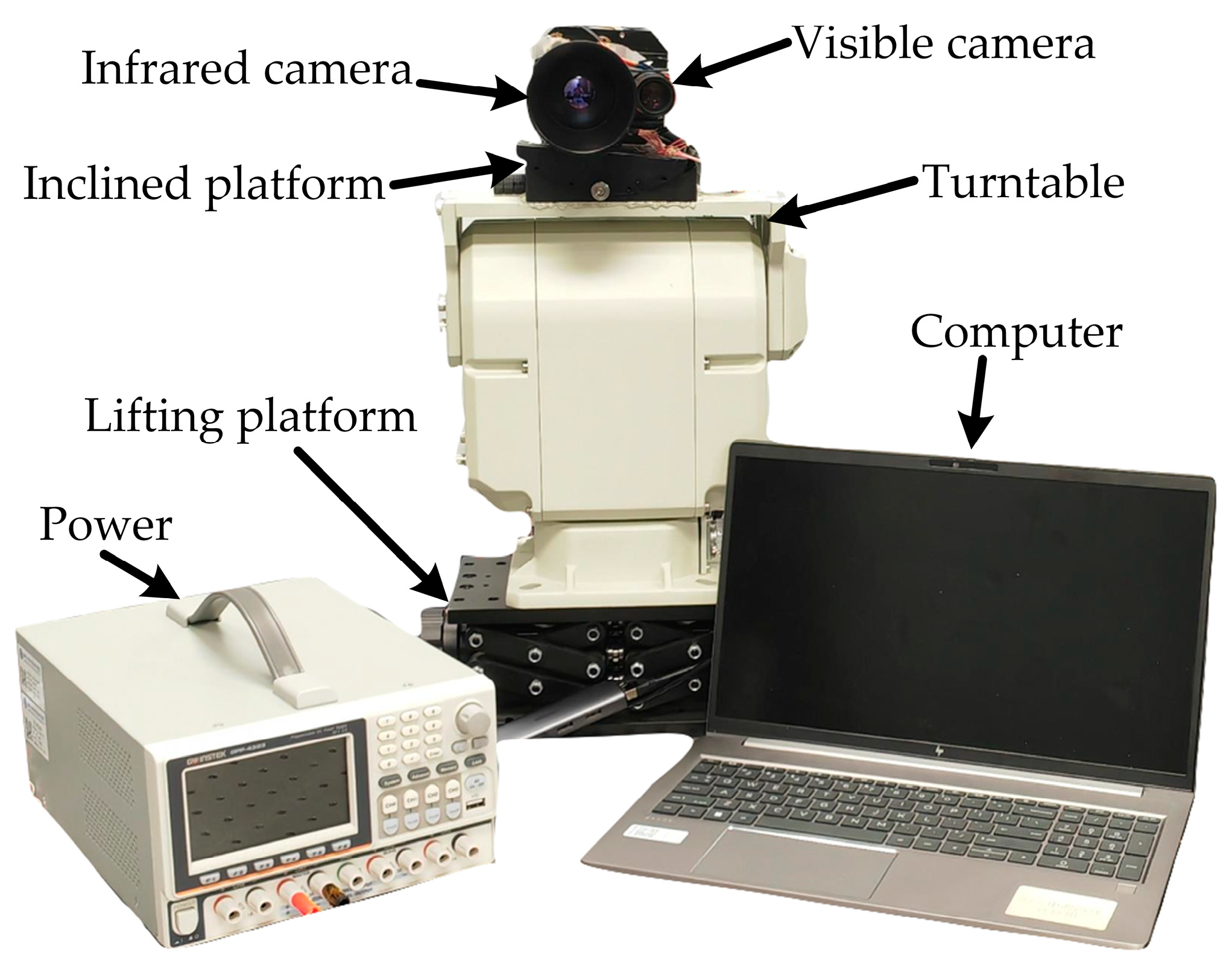
2. Materials and Methods

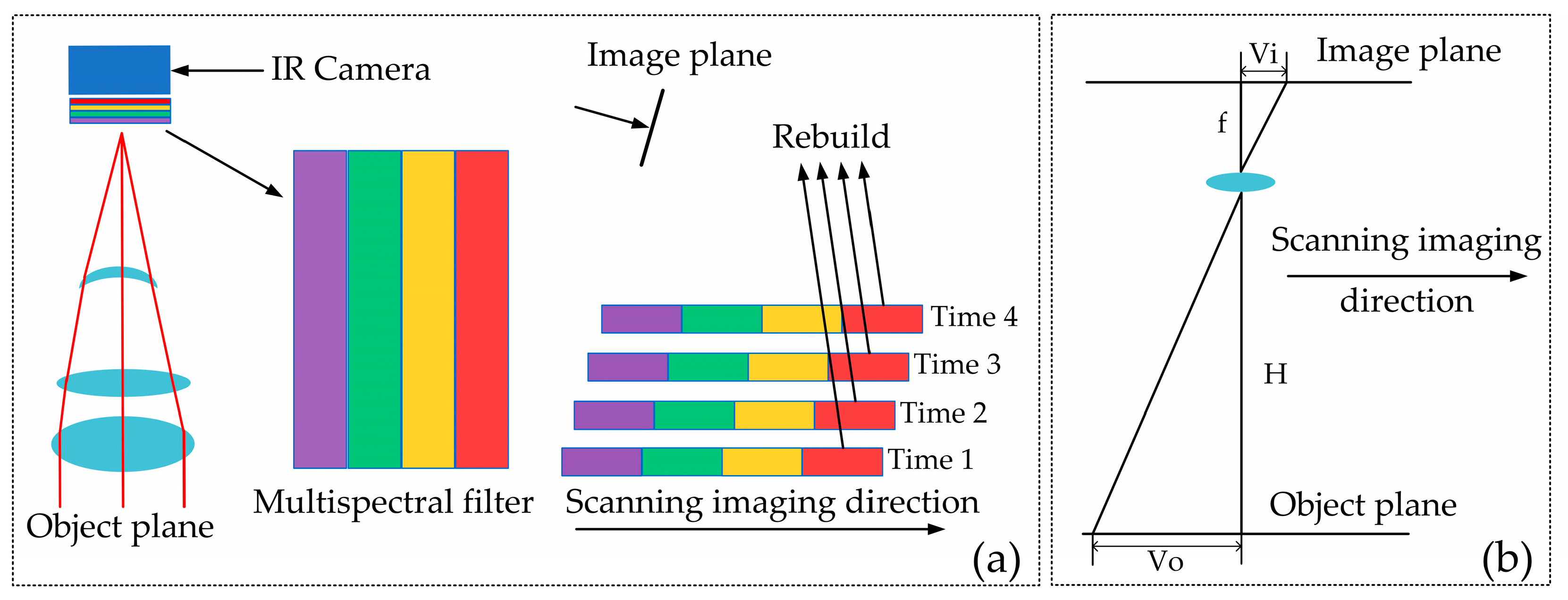
2.1. Velocity-Height Ratio Matching Model

The push-broom imaging mechanism for a multispectral IR camera is illustrated in Figure 1a. The IR camera receives IR radiation from the target, filters it through a spectral filter, and projects the energy distribution pattern onto the focal plane. A 4-channel filter is placed in front of the uncooled IR focal plane array, enabling spectral separation across different fields of view and facilitating push-broom imaging. Once the imaging is completed, the multi-frame 4-channel images are rebuilt. In the push-broom imaging process (Figure 1b), the image shift velocity on the focal plane, V i , can be geometrically expressed as [14]:
V i = f V o H
where f is the lens focal length; H is the distance from the lens optical center to the object; and V o is the object velocity.
In an optical system with fixed lens parameters, the image shift velocity on the focal plane is strongly correlated with the velocity-height ratio. There exist two main requirements for velocity-height ratio matching, i.e., (i) compatibility between the velocity-height ratio and the sampling frequency, and (ii) stability of the matching over time. Matching the velocity-height ratio during push-broom imaging ensures a fixed image space movement between adjacent frames along the push-broom direction [15]. Nevertheless, in actual push-broom scenarios, variations in velocity and height can result in discrepancies in the ratio, and the imaging model for velocity-to-height ratio discrepancies and attitude alterations is illustrated in Figure 2. Therefore, it is essential to develop real-time image shift velocity calculation techniques considering camera posture changes.
Existing methods for obtaining the velocity-height ratio can be primarily divided into direct measurement and indirect calculation. Direct measurement involves using the altitude and velocity data, obtained from attitude and orbit control devices on the carrier, to compute the velocity-height ratio [5]. Indirect calculation, on the other hand, relies on back-calculating the velocity-height ratio using Equation (1), derived from the image velocity measured by external devices on the image plane [16]. Several methods exist for indirect calculation of the velocity-height ratio, such as spatial filtering [17], scan correlation [18], optical path difference [19], and heterodyne detection [20]. The high-resolution visible camera image matching method proposed in this study allows for both real-time capture of image motion in the push-broom scan direction and the computation of image motion and attitude changes in the direction perpendicular to it.

2.2. Off-Chip Digital Domain TDI

Tao et al. [15,21] first proposed a TDICMOS camera with an off-chip digital accumulator. Building on their model, we conducted off-chip digital domain TDI outside the IR camera module. This setup utilized a field-programmable gate array (FPGA) to provide power, clock, and control for both the visible and IR cameras (Figure 3); the components work as follows: (i) the FPGA_1 board receives multispectral array data from the IR camera, performs digital domain TDI in memory, and outputs the integrated image signal; and (ii) the FPGA_2 board receives data from the visible camera, calculates compensation parameters, and sends them to the FPGA_1 board. FPGA_1 then uses these parameters to control the IR camera sampling frequency via clock in real time and corrects the integration units in memory. The computer/satellite platform can receive the IR and visible data streams from FPGA_1 and FPGA_2, respectively, and can adjust specific FPGA_1 parameters, such as the integration unit positions and the number of accumulations, via controller area network (CAN) communication.
Consider an initial example of three-level integration. Under conditions of matched velocity-height ratio and in the absence of camera posture interference, adjacent frames maintain a pixel shift exclusively along the push-broom scan direction (Figure 4). The horizontal and vertical axes represent the directions along and perpendicular to the push-broom scan, while the time axis represents IR data stream reception timing. The pixel value at the x-th row and y-th column of the (n × 3) integration unit at time instance i is denoted as Pi(x, y). At time1, the third column of the array corresponds to the same scene as the second column at time2 and the first column at time3. At time1, the integration unit is input as a new matrix and added to the existing matrix output from the previous time instance. The enhanced result is output from the leftmost column, while the matrix shifts to the left by one column and is saved in memory. This process is repeated at time2 and time3, leading to the integrated output of three imaging results corresponding to the same object space.

2.3. Registration Relationship Between the IR and Visible Cameras

Due to differences in manufacturing processes, wavelength characteristics, and sensitivity, the pixel sizes of visible detectors range from 3.0 to 10.0 μm [22], while those of uncooled mid-to-long IR wavelength detectors range from 10.0 to 30.0 μm [23]. In this study, the visible and IR cameras had a pixel size of 5.86 μm and 12.00 μm, respectively, with both cameras using 50 mm fixed-focus lenses.
The spatial resolution of the visible camera is more than twice that of the infrared camera. Moreover, the pixel count of the visible camera is 10 times greater than that of a single spectral channel in the infrared camera. As a result, the use of a high-resolution visible light camera allows for more accurate identification of attitude changes and image shift velocities. The affine relationship between the spatial resolutions of the two cameras was used to transfer posture and image shift information to the off-chip digital TDI FPGA board of the IR camera. To establish this relationship, the two cameras were parallelly aligned by calculating the angle between their optical axes using a photoelectric autocollimator (Figure 5). Through experimental verification, the angle between the optical axes of the two cameras was found to be less than 0.00024 rad; thus, the optical axes of the visible camera and the infrared camera can be considered parallel.

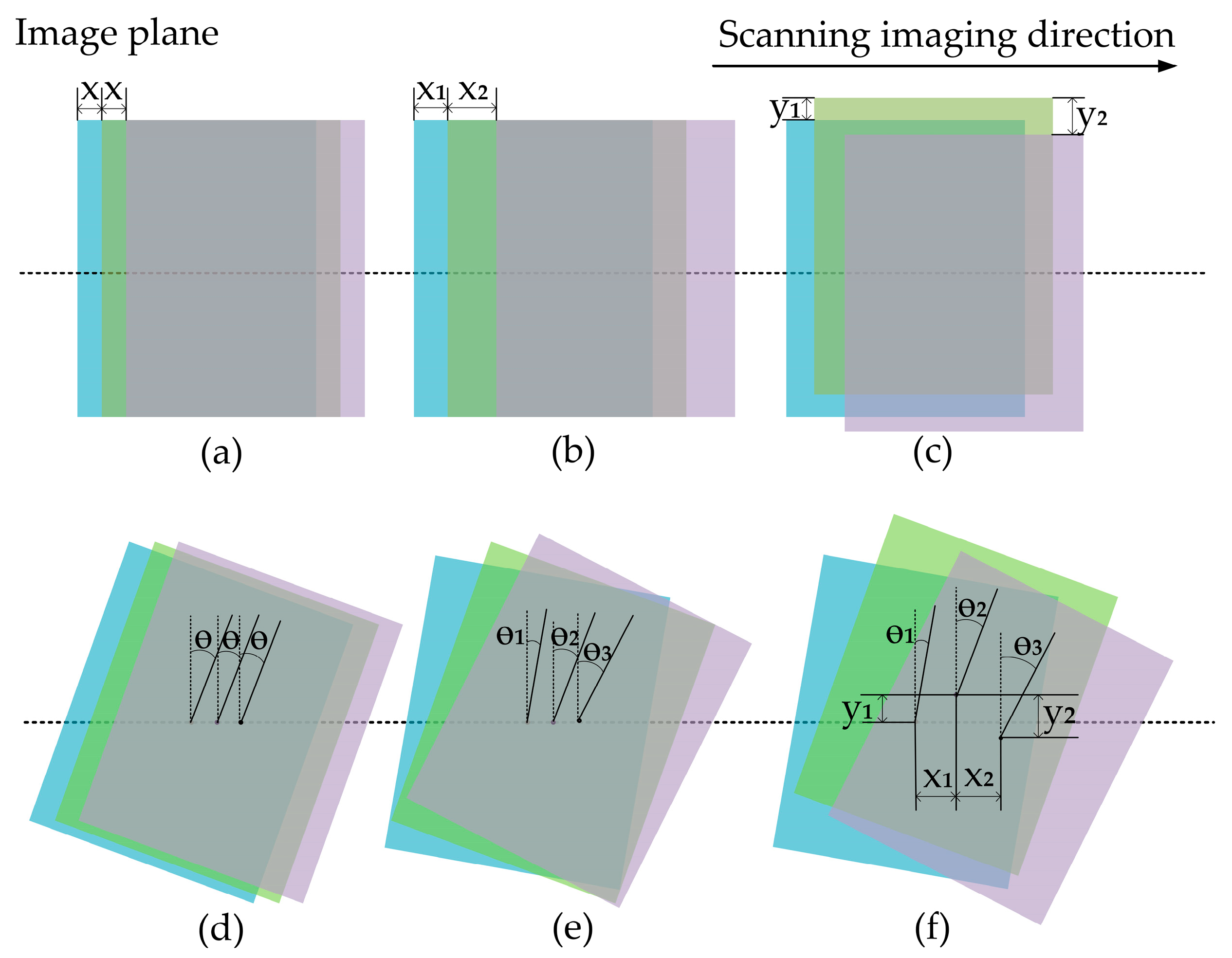
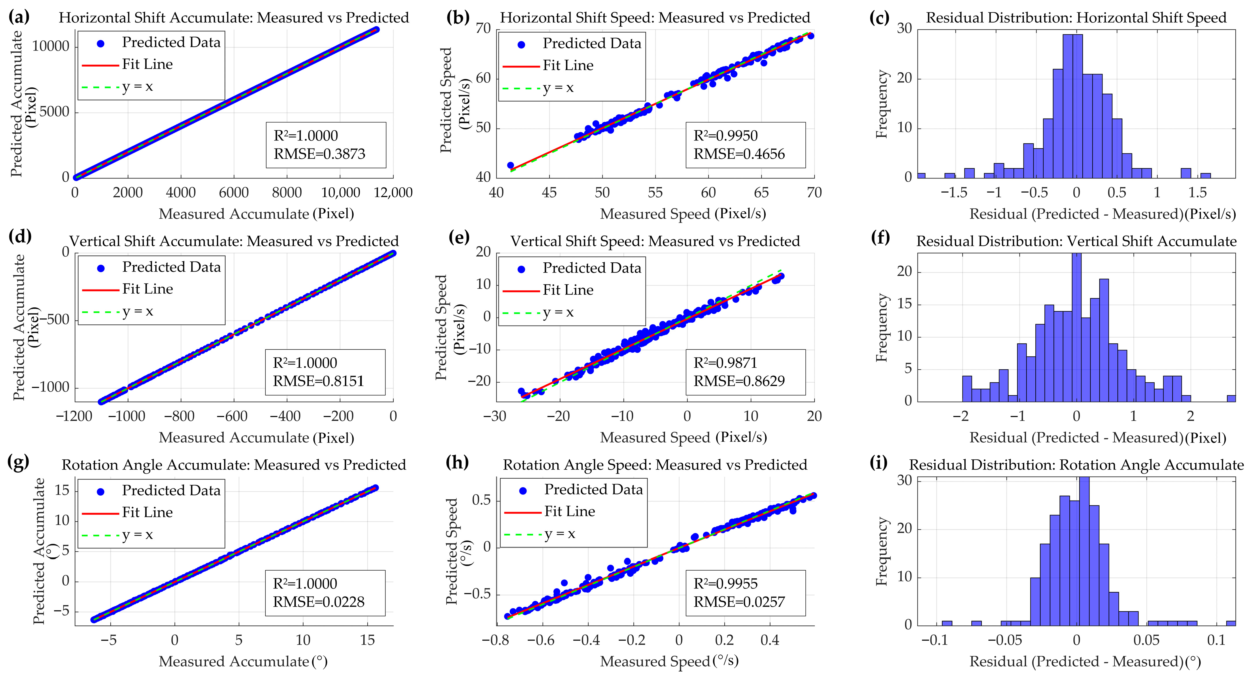
2.4. Image Rotation and Shift Calculation

Initially, we preprocessed the visible image to enhance its contrast and allow an easier selection of more feature points to improve calculation accuracy. The original pixel value, I a d ( x , y ) , is updated as:
I a d ( x , y ) = I x , y min I max I min I
where min I and max I are the minimum and maximum pixel values, respectively.
Subsequently, feature point detection was conducted by applying the sped-up robust features (SURF) [24] and oriented FAST and rotated BRIEF (ORB) algorithms on local image features. ORB combines FAST feature detection with BRIEF descriptors [25], while SURF calculates feature points using the determinant of the Hessian matrix, expressed as:
H ( x , y ) = L x x ( x , y ) L x y ( x , y ) L x y ( x , y ) L y y ( x , y )
where L x x , L x y , and L y y are the second-order derivatives of a function L ( x , y ) .
We utilized the random sample consensus (RANSAC) algorithm to estimate the geometric transformation model by randomly selecting the minimum number of matching points, computing the similarity transformation model, and selecting points with errors below a preset threshold as inliers until the model with the most inliers was obtained. The aforementioned similarity transformation model [26] can be represented as:
x y = T x y 1 = s cos θ s sin θ t x s sin θ s cos θ t y 0 0 1
where s = 1 is the scaling factor; θ is the relative rotation angle between two frames; and t x and t y are the horizontal and vertical image shifts, respectively. Feature point matching was performed by calculating the Euclidean distance between two feature vectors, f1 and f2, as:
d ( f 1 , f 2 ) = i = 1 n ( f 1 i f 2 i ) 2
Misaligned feature points were eliminated by calculating the mean and standard deviation of the Euclidean distances, setting a 95% confidence interval to filter valid matching points. These valid points were then used to recompute the geometric transformation; calculate the image rotation angle, θ ; perform rotation compensation; and compute t x and t y . Finally, the compensated image shifts were merged with the previous frame (Figure 6).

2.5. Prediction and Affine Transformation

Using the above-described method, the changes in image rotation and horizontal and vertical shifts for each moment relative to the previous one can be determined over a continuous period. Using this information in conjunction with a Kalman filter [27], it is possible to predict the rotation, vertical motion, and horizontal velocity of the image.
In the image rotation prediction model, let us define a state vector, x k , as:
x k = θ ( t ) ω ( t )
where k is the discrete time step; t is a specific moment in the continuous model; θ ( t ) is the cumulative image rotation; and ω ( t ) is the rate of change of image rotation. A measurement vector, z k , can then be defined as:
z k = θ ω = θ θ t
assuming linear changes in image rotation between frames, where the change in image rotation, θ , can be computed as the product of the ω and the time interval, t . The state transition between two time steps can be described using the transition matrix, A , expressed as:
A = 1 t 0 1
where t = 1 / F P S v i s . The measurement matrix, H, can then be defined as:
H = 1 0 0 1 t
In the Kalman filter, the prediction phase and update steps are crucial for integrating new observation information into the current state estimate to improve system state predictions [27]. The prediction phase is executed as follows:
x ^ k = A x ^ k 1 P k = A P k 1 A T + Q
where x ^ k is the predicted state at time k ; x ^ k 1 is the state estimation at time ( k 1 ); P k is the error covariance of the prediction; A T is the transpose of A ; and Q is an estimate of the state prediction uncertainty (i.e., process noise).
Upon obtaining new observations, the Kalman filter adjusts the prediction through the following update step:
K k = P k H T H P k H T + R 1 x ^ k = x ^ k + K k ( z k H x ^ k ) P k = ( I K k H k ) P k
where K k is the Kalman gain, which determines the weight of the observed data relative to the predicted data; H T is the transpose of H ; R is the measurement noise; x ^ k is the updated state estimate, which reduces the prediction–observation discrepancy; I is the identity matrix; and P k is the updated error covariance, reflecting the uncertainty level after state estimation.
We verified the prediction accuracy of the above-described prediction model by comparing the angular velocity calculated from the simulated measured attitude angle change with the predicted angular velocity corresponding to the next time step (Figure 7). The model demonstrated a coefficient of determination of R2 = 0.7284 and a root mean square error (RMSE) of 0.0464, indicating that it can accurately predict the camera’s attitude in subsequent time steps and effectively compensate for the time lag issues in image shift and rotation calculations.
Thus, the cumulative image shift prediction, θ v i s t , for future moments based on the visible camera can be computed using the established Kalman model [Equations (10) and (11)], along with the predictions for horizontal shift velocity, v x _ i r t , and the cumulative vertical shift, t y _ i r t . The attitude changes for both cameras are equivalent, with image shift variations affine to their resolutions. These aspects can be expressed as:
θ i r t = θ v i s t v x _ i r t = I F O V v i s I F O V i r · v x _ v i s t t y _ i r t = I F O V v i s I F O V i r · t y _ v i s t
where θ i r t and θ v i s t are the cumulative image rotations; v x _ v i s t and v x _ i r t are the horizontal shift velocities; t y _ i r t and t y _ v i s t are the cumulative vertical shifts; and I F O V i r and I F O V v i s are the spatial resolutions of the IR and visible cameras, respectively.

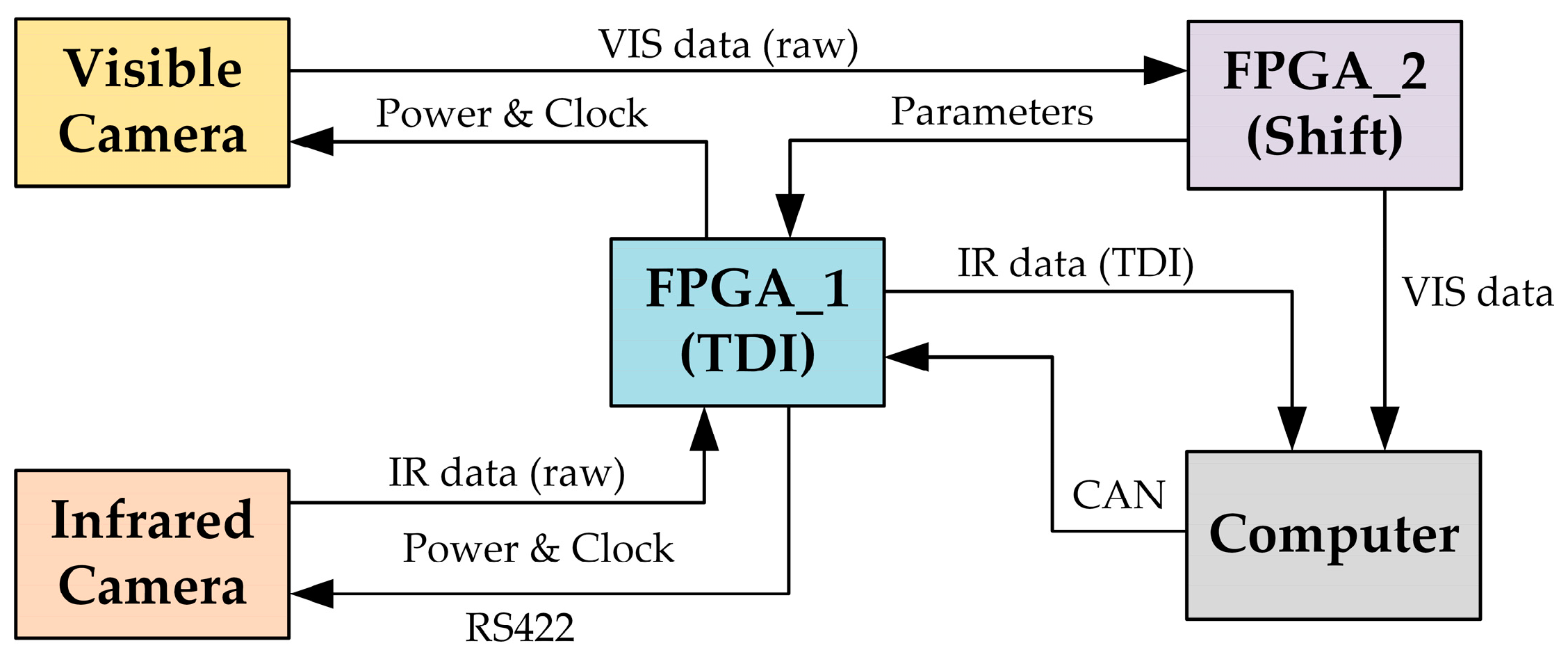
2.6. Compensation Model

Using Equation (12), we can obtain θ i r t , v x _ i r t , and t y _ i r t for the IR camera at time t. To avoid altering the column area of the integration unit in the horizontal direction, the sampling frequency of the IR camera was adjusted in real-time to compensate for the horizontal shifts. For a horizontal shift of m pixels between adjacent frames, the adjusted sampling frequency, F P S i r , can be expressed as:
F P S i r = v x _ i r t m
The real-time corrected IR image at t is transmitted to the FPGA, where image rotation compensation for each channel is performed using θ i r t as:
x y 1 t = cos θ i r t sin θ i r t 0 sin θ i r t cos θ i r t 0 0 0 1 x y 1 t
After frequency correction and image rotation compensation, the vertical shift t y _ i r t is compensated through interpolation as:
x y 1 t = 1 0 0 0 1 t y _ i r t 0 0 1 x y 1 t
Following these steps, image shift and rotation compensation between adjacent frames of the IR camera was achieved within the FPGA memory. The updated images were then selected for integration unit areas for the digital domain TDI. Illustrated in Figure 8 is the overall workflow of the real-time compensation model as proposed in this study.

3. Results

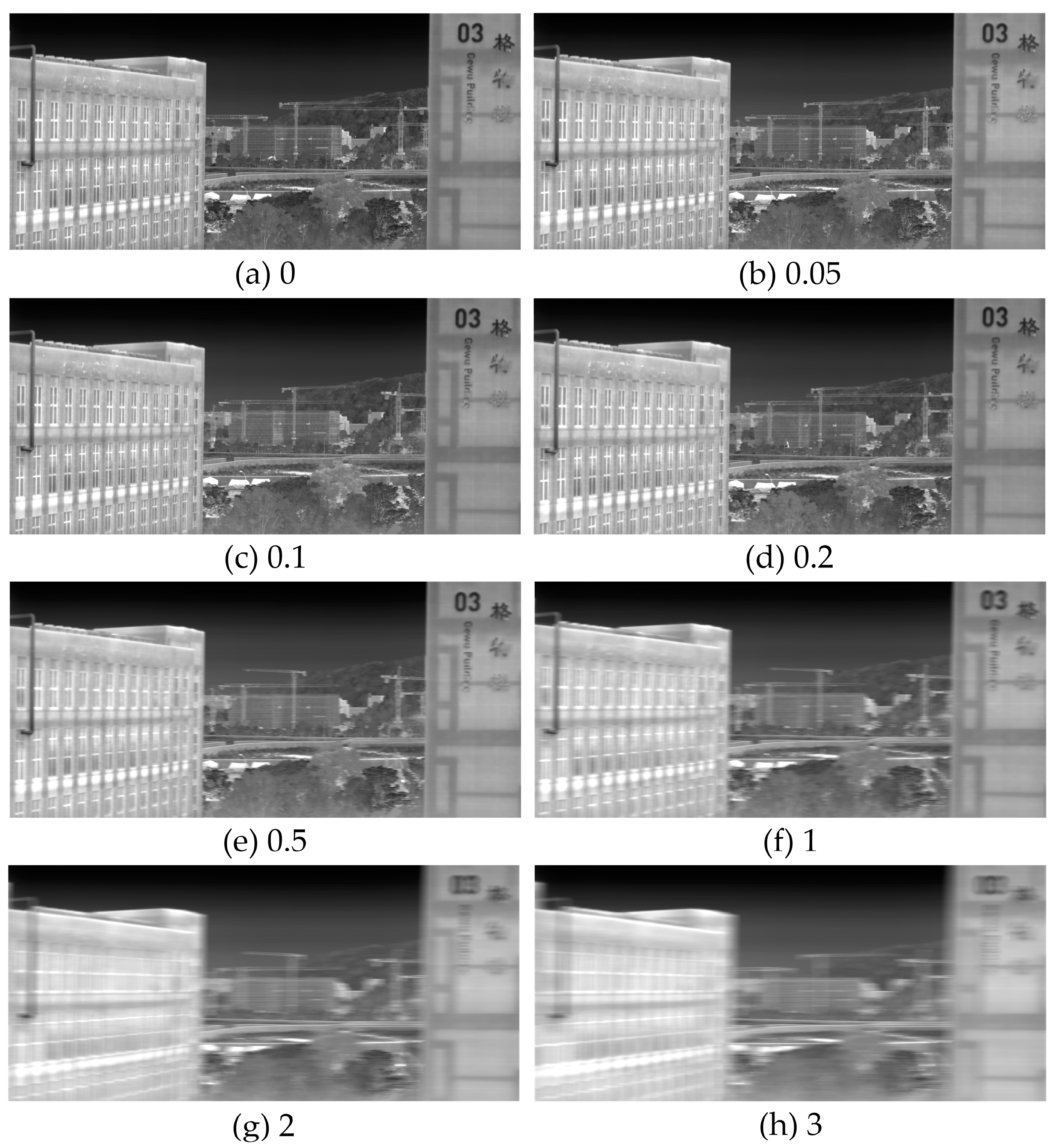
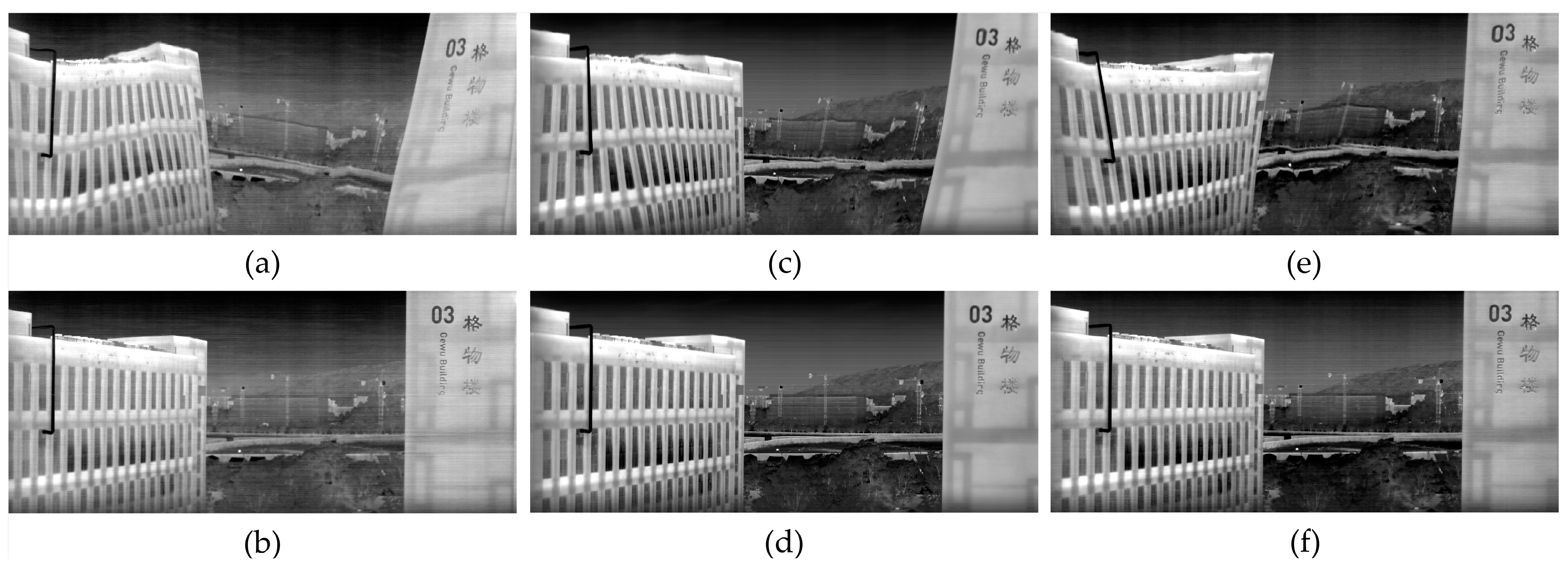
3.1. Image Shift and Rotation Effects

To validate the necessity and effectiveness of the proposed method, we conducted a series of ground-based imaging experiments. The visible and IR cameras were mounted along the push-broom direction on an inclined platform (Figure 9). Among them, the spatial resolutions of the visible and infrared cameras were 58.6 m@500 km and 120 m@500 km, respectively. The four-channel filter of the infrared camera covered the following spectral bands: 3–5 µm, 8–12.5 µm, 10.5–11.5 µm, and 11.5–12.5 µm. The platform was vertically mounted on a turntable, which in turn was vertically mounted on the lifting platform. Through the manipulation of the turntable’s horizontal rotation velocity, the inclination angle of the camera platform, and the elevation of the lifting platform, we simulated variations in horizontal image displacement velocity, cumulative image rotation, and cumulative vertical image displacement during the push-broom imaging process. The TDI images generated by the infrared multispectral camera were acquired using the self-developed upper computer software “HGYIR.v2.0” on the computer.
Initially, we investigated the impact of image displacement along the push-broom direction on TDI results without applying any compensation measures. To eliminate vertical jitter and maintain a camera inclination angle of 0°, we modified the turntable’s horizontal rotation speed while preserving a steady external trigger frequency for the IR camera. This experimental setup enabled the simulation of various degrees of horizontal image displacement between consecutive frames in the infrared (IR) images. The 30-level TDI results at varying turntable velocities without compensation demonstrated that with increasing image displacement, the TDI output image quality exhibited progressive deterioration (Figure 10).
Our subsequent analysis focused on evaluating the influence of various inclination angles on the quality of TDI imaging, without employing any compensatory measures. Through the maintenance of consistent IR camera sampling frequency, turntable speed, and vertical elevation stage, the camera inclination was adjusted utilizing the gimbal platform. Analysis of the 30-level TDI outcomes under these experimental conditions unveiled geometric distortions and blurring effects attributable to the alterations in camera inclination (Figure 11). As the inclination angle increased, the degree of image distortion became more pronounced.
The cross-correlation function serves as a quantitative approach for assessing the resemblance between two images by evaluating the degree of distortion in one image relative to a designated reference image. To conduct a more objective evaluation of the impact of inclination angles on TDI imaging results, we utilized a cross-correlation function, R f g , defined as:
R f g ( m , n ) = 1 N i j ( f i , j μ f ) ( g i + m , j + n μ g ) σ f σ g
where f i , j is the pixel value of the reference image; g i + m , j + n is the pixel value of the target image at position i + m , j + n ; N is the total number of pixels over the summation; μ f and μ g are the mean values of images f and g , respectively; and σ f and σ g are the standard deviations of images f and g , respectively.
The normalized cross-correlation coefficients for imaging results at inclination angles of 5°, 10°, and 20° relative to 0° were 0.907, 0.867, and 0.811, respectively. Therefore, compensating for unknown image displacement and rotation caused by posture and trajectory variations is crucial.

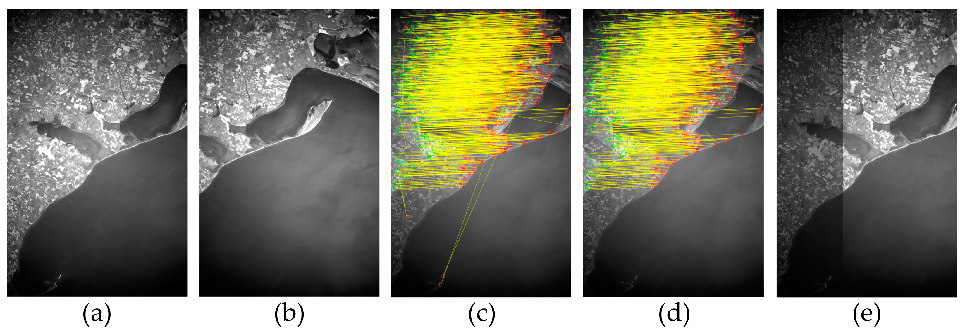
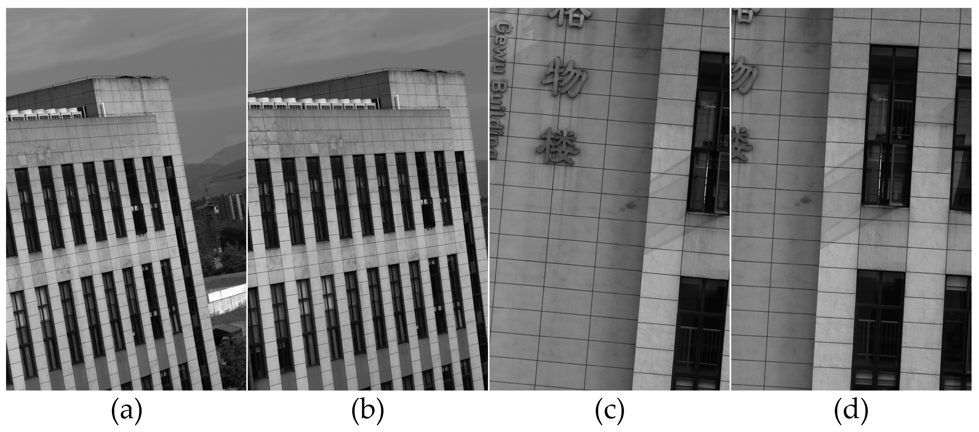
3.2. Real-Time Compensation Effects

Indeed, the efficacy of the real-time self-compensation method proposed in this paper is highly dependent on the computational accuracy and prediction accuracy of image shift and rotation. To verify the prediction accuracy of the prediction model, we introduced artificial interference to simulate image shift and rotation during the imaging process. During the push-broom imaging process, we adjusted the horizontal rotation speed of the turntable, camera inclination angle, and elevation stage height in real-time to simulate unknown image displacement and rotation. Figure 12 presents the results of the visible camera imaging the outdoor target scene at four distinct moments during the push-broom process. By analyzing two adjacent frames, such as those shown in Figure 12a,b, as well as Figure 12c,d, the image shift and rotation information during the push-broom process can be calculated.
The horizontal image shift accumulation, horizontal image shift velocity, vertical image shift accumulation, vertical image shift velocity, image rotation accumulation, and image rotation velocity at each time step were obtained through the utilization of visible camera inter-frame image calculations during the push-scan imaging process under conditions of introduced human interference. Subsequently, utilizing these calculated image shifts and image spins as inputs for the Kalman prediction model, the image shifts and image spins for the subsequent time step could be predicted in real time. To evaluate the accuracy of the predicted values, scatter plots of the predicted and measured values are presented for the horizontal image shift accumulation (Figure 13a), the horizontal image shift velocity (Figure 13b), the vertical image shift accumulation (Figure 13d), the vertical image shift velocity (Figure 13e), the image rotation accumulation (Figure 13g), and the image rotation velocity (Figure 13h). Furthermore, the coefficients of determination (R2) and the root mean squared error (RMSE) are calculated and presented on the scatter plots. Moreover, Figure 13 displays histograms that elucidate the prediction error distribution for three key parameters: horizontal image shift velocity (Figure 13c), vertical image shift accumulation (Figure 13f), and image rotation accumulation (Figure 13i).
The fitted curves of the cumulative values for image shift and rotation demonstrate alignment with y = x, while the fitted curves of the velocity for image shift and rotation also coincide with y = x. The RMSE values are observed to be less than 1, indicating that the predicted values exhibit lower error compared to the measured values. Consequently, these predictions effectively forecast the state of the subsequent time step. The histogram of the prediction error distribution for the three key variables demonstrates the distribution of prediction errors for each variable. The errors exhibit an approximately normal distribution, with concentrations in the ranges of (−1, 1) pixels/s for horizontal image shift velocity, (−2, 2) pixels for vertical image shift accumulation, and (−0.05, 0.05)° for image rotation accumulation. The prediction error of the infrared image displacement obtained from the visible-light camera in conjunction with the Kalman prediction model is within 1 pixel following the spatial resolution affine transformation relationship (Equation (12)) between the infrared camera and the visible-light camera. This validates the accuracy and stability of the image shift image rotation quantities predicted in real time by the Kalman prediction model.
Finally, utilizing the proposed real-time compensation model for unknown image shift and rotation, we conducted imaging experiments under varying conditions of mixed attitude, horizontal displacement velocity, and dynamic vertical displacement, and obtained compensated TDI imaging results (Figure 14b,d,f). Concurrently, we established a control group consisting of traditional TDI imaging results under the same conditions of mixed attitude, horizontal shift, and vertical shift changes, but without any compensation measures (Figure 14a,c,e). Under traditional conditions without the compensation algorithm, the TDI images exhibit severe geometric distortion and deformation. Since different spectral channels imaged the same target scene at different times, the TDI images of 3–5 μm, 8–12.5 μm, and 11.5–12.5 μm under traditional uncompensated conditions, which are affected by image shift and rotation, exhibited varying geometric distortions and artifacts. Additionally, vertical shift disturbances caused localized pulse-like artifacts. However, the proposed real-time compensation model significantly improved the output TDI image quality of the output TDI images across all spectral channels by reducing both the trailing blur caused by image displacement and geometric distortion caused by image rotation. The aforementioned results demonstrate the efficiency and practicality of the proposed method in this paper for real-time compensation of TDI image degradation caused by mixed image shift and rotation variations during the push-broom imaging process.
To objectively evaluate the effectiveness of the proposed real-time compensation algorithm for addressing image shift and rotation, we employed three no-reference image quality assessment metrics [28], namely, blind and reference-less image spatial quality evaluator (BRISQUE), natural image quality evaluator (NIQE), and perception-based image quality evaluator (PIQE) (Table 1). Both BRISQUE and NIQE measure image distortion by analyzing natural scene statistical features in the spatial domain. These metrics can detect image quality differences before and after compensation, with higher scores indicating poorer image quality. PIQE focuses on human visual perception and assesses image distortion by examining block-level features within the image. An increased number of low-quality blocks leads to a higher PIQE score, indicating lower image quality. Particularly for the BRISQUE metric, the image obtained by the proposed method showed a 21.37% improvement in image distortion compared to the traditional method, indicating that the image quality was superior to that of images obtained without any compensation measures.

4. Discussion

The experimental investigation of image shift and rotation effects revealed critical challenges in uncompensated time-delay integration (TDI) imaging. First, uncompensated horizontal image shift along the push-broom scan direction resulted in progressive deterioration of image quality, with trailing blur intensifying proportionally to displacement magnitude (Figure 10). Second, camera inclination-induced rotational deviations caused significant geometric distortions (Figure 11), as evidenced by a marked decline in normalized cross-correlation coefficients (0.811 at 20°; Equation (16)), highlighting a 18.9% reduction in image fidelity under moderate rotational perturbations. Third, the combined effects of horizontal and vertical image shifts, along with image rotation, introduced spatially localized artifacts and geometric distortions in the multispectral TDI images (Figure 14a,c,e). These distortions manifested as misalignments and structural deformations across spectral channels, severely compromising the structural integrity and radiometric consistency of the acquired imagery. Such artifacts are particularly detrimental in multispectral imaging, where precise spatial registration between channels is essential for accurate data interpretation and analysis. The observed degradation underscores the necessity of real-time compensation to mitigate these complex, multidimensional motion-induced distortions, ensuring the preservation of image quality and structural fidelity in dynamic imaging scenarios.
To address these challenges, the proposed methodology integrates a high-resolution visible camera with a Kalman filter-based predictive framework, enabling real-time compensation for unknown displacements and rotations in infrared multispectral TDI imaging. Experimental validation demonstrates that the proposed method is capable of generating high-quality compensated TDI images, as evidenced by the enhanced structural integrity and reduced artifacts (Figure 14b,d,f). Notably, the method achieves substantial improvements in quantitative image quality metrics. For instance, in the 8–12.5 μm spectral channel, the compensated images exhibit a 21.37% enhancement in the BRISQUE score compared to uncompensated results (Table 1), underscoring the algorithm’s effectiveness in mitigating motion-induced distortions and preserving image fidelity. This success can be attributed to three key factors: (1) the high spatial resolution of the visible camera enables sub-pixel accuracy in calculating image shifts and rotations, which translates to precise compensation for the lower-resolution IR camera; (2) the Kalman filter effectively mitigates the latency in parameter prediction, enabling accurate forecasting of image shift and rotation parameters for subsequent time steps. Specifically, the prediction accuracy achieves a horizontal image shift velocity within (−1, 1) pixels/s, a vertical image shift accumulation within (−2, 2) pixels, and an image rotation accumulation within (−0.05, 0.05)°. This high precision ensures robust real-time adaptability to dynamic imaging conditions, which is critical for maintaining image quality in high-dynamic-range environments; and (3) the affine transformation relationship between the dual-mode sensors allows seamless mapping of motion parameters, eliminating the need for complex hardware compensation systems.
However, due to inherent optical aberrations in the lens system and limitations in the precision of optical axis parallelism between the two cameras, the affine transformation relationship governing image displacement and rotation between the multispectral infrared camera and the visible camera may deviate from the ideal model described by Equation (12). To address this limitation, future research could focus on implementing laboratory-based geometric calibration to refine the affine transformation parameters between each spectral channel of the infrared multispectral camera and the visible camera. This calibration process would systematically characterize and correct for optical aberrations and alignment inaccuracies, thereby enhancing the precision and robustness of the compensation framework. Such an approach is particularly critical in applications demanding sub-pixel registration accuracy, as it would mitigate the impact of optical imperfections and optical axis misalignment. By ensuring consistent and reliable performance across diverse imaging conditions, this method could significantly improve the operational stability of the system in real-world scenarios.

5. Conclusions

In this study, we propose a novel method to address image displacement and rotation caused by posture and trajectory variations during push-broom imaging using IR multispectral area array cameras by leveraging a high-resolution visible camera. This approach aids the accurate identification of changes in image displacement and rotation and predicts further variations using a Kalman filter. By utilizing the affine relationship of the image shift between the IR and visible cameras for real-time correction, the integration unit achieves self-compensation for unknown displacements and rotations. Compared to traditional optical and mechanical compensation algorithms, this method offers significant advantages in terms of cost and weight reduction. It also ensures rapid and precise calculation of minor displacements and rotations, along with accurate classification. Experimental results confirm that the proposed algorithm produces high-quality TDI images even in high-dynamic-range imaging scenarios.
However, this method currently exhibits certain limitations. Under extreme low-light conditions at night, the images captured by the visible camera may lack sufficient feature points to accurately calculate image shift and rotation information, which could render the system inoperable. In our future work, to address the limitations of the visible camera in nighttime scenarios, we plan to utilize a low-light camera or a large-array-scale infrared camera without a spectral filter, combined with an optical lens featuring a longer focal length, to achieve high-precision calculation of image shift and rotation. Additionally, the current approach only considers image rotation within a two-dimensional plane, whereas real-world scenarios may involve additional attitude changes such as pitch. In the future, we will focus on developing real-time compensation algorithms for three-dimensional attitude rotation in practical scenarios, aiming to achieve better compensated TDI results in more complex environments.

Author Contributions

Conceptualization, T.Z. and G.T.; methodology, T.Z. and F.D.; software, T.Z., G.T. and W.W.; validation, T.Z., G.T. and F.D.; investigation, J.B. and F.D.; data curation, T.Z. and F.D.; writing—original draft preparation, T.Z. and G.T; writing—review and editing, T.Z., S.Z. and G.T; visualization, T.Z. and S.Z.; supervision, G.T.; project administration, C.L.; funding acquisition, J.W. All authors have read and agreed to the published version of the manuscript.

Funding

This research was funded by 2023C03012 Key Technologies and Equipment for High-Resolution Imaging Spectrometers—High-Resolution Spectral Imaging Instrument Payload, and 2024C03032 Key Technologies and Equipment for Marine Sensors.

Data Availability Statement

The original contributions presented in the study are included in the article. Further inquiries can be directed to the corresponding author.

Conflicts of Interest

The authors declare no conflicts of interest.

References

  1. Shen, Y.; Yan, Z.; Yang, Y.; Tang, W.; Sun, J.; Zhang, Y. Application of UAV-Borne Visible-Infared Pushbroom Imaging Hyperspectral for Rice Yield Estimation Using Feature Selection Regression Methods. Sustainability 2024, 16, 632. [Google Scholar] [CrossRef]
  2. Langer, D.D.; Johansen, T.A.; Sørensen, A.J. Consistent Along Track Sharpness in a Push-Broom Imaging System. In Proceedings of the IGARSS 2023–2023 IEEE International Geoscience and Remote Sensing Symposium, Pasadena, CA, USA, 16–21 July 2023; pp. 4486–4489. [Google Scholar]
  3. Fan, C.; Li, Y.-C.; Yi, H.-W. Influence of Velocity-Height Ratio of Satellite on the TDICCD Camera. Acta Armamentarii 2007, 28, 817–821. [Google Scholar]
  4. Hu, J.; Zhi, X.; Gong, J.; Yin, Z.; Fan, Z. Error Tolerance and Effects Analysis of Satellite Vibration Characteristics and Measurement Error on TDICCD Image Restoration. Infrared Phys. Technol. 2018, 93, 277–285. [Google Scholar]
  5. Chen, X.; Zhan, H.; Fan, S.; Rao, Q.; Hong, Z.; You, Z.; Xing, F.; Liu, C. High-Accuracy Real-Time Attitude Determination and Imagery Positioning System for Satellite-Based Remote Sensing. IEEE Trans. Geosci. Remote Sens. 2023, 61, 1001314. [Google Scholar]
  6. Drouin, M.-A.; Fournier, J. Infrared and Visible Image Registration for Airborne Camera Systems. In Proceedings of the 2022 IEEE International Conference on Image Processing (ICIP), Bordeaux, France, 16–19 October 2022; pp. 951–955. [Google Scholar]
  7. Yang, Y.; Yu, C.; Wang, Y.; Hua, N.; Kuang, H. Imaging Attitude Control and Image Motion Compensation Residual Analysis Based on a Three-Axis Inertially Stabilized Platform. Appl. Sci. 2021, 11, 5856. [Google Scholar] [CrossRef]
  8. Wang, L.; Liu, X.; Wang, C. Modeling and Design of Fast Steering Mirror in Image Motion Compensation for Backscanning Step and Stare Imaging Systems. Opt. Eng. 2019, 58, 103105. [Google Scholar]
  9. Li, W.; Hu, C.; Zhang, L.; Yan, C. Drift Angle Compensation Method for a High-Resolution and Wide-Range Space Camera. Measurement 2020, 158, 107710. [Google Scholar]
  10. Chang, S.; Chen, W.; Cao, J.; Mei, C.; Li, X.; Zhang, H. Research on 2D Image Motion Compensation for a Wide-Field Scanning Imaging System with Moving Base. Photonics 2023, 10, 1305. [Google Scholar] [CrossRef]
  11. Sun, Y.; Zeng, J.; Li, Y.; Rao, P.; Hu, T. Compensation Method for the Image Motion of a Rotary-Scan Space Camera. Opt. Quantum Electron. 2020, 52, 502. [Google Scholar]
  12. Li, J.; Liu, Z. High-Resolution Dynamic Inversion Imaging with Motion-Aberrations-Free Using Optical Flow Learning Networks. Sci. Rep. 2019, 9, 11319. [Google Scholar] [CrossRef] [PubMed]
  13. Zhang, G.; Xu, Y.; Liu, C.; Xie, P.; Ma, W.; Lu, Y.; Kong, X. Study of the Image Motion Compensation Method for a Vertical Orbit Dynamic Scanning TDICCD Space Camera. Opt. Express 2023, 31, 41740–41755. [Google Scholar] [PubMed]
  14. Liang, S.; Li, X.; Wang, J. Geometric Processing and Positioning Techniques. Advanced Remote Sensing; Elsevier: Oxford, UK, 2012; pp. 33–74. [Google Scholar]
  15. Tao, S.; Zhang, X.; Xu, W.; Qu, H. Realize the Image Motion Self-Registration Based on TDI in Digital Domain. IEEE Sens. J. 2019, 19, 11666–11674. [Google Scholar]
  16. Atkins, M. Velocity Field Measurement Using Particle Image Velocimetry (PIV). In Application of Thermo-Fluidic Measurement Techniques; Elsevier: Amsterdam, The Netherlands, 2016; pp. 125–166. [Google Scholar]
  17. Li, M.; Feng, G.; Deng, R.; Gao, F.; Gu, F.; Ball, A.D. Structural Vibration Mode Identification from High-Speed Camera Footages Using an Adaptive Spatial Filtering Approach. Mech. Syst. Signal Process. 2022, 166, 108422. [Google Scholar]
  18. Jackson, F.; Walton, W.; Baker, P. Aircraft and Satellite Measurement of Ocean Wave Directional Spectra Using Scanning-Beam Microwave Radars. J. Geophys. Res.-Ocean. 1985, 90, 987–1004. [Google Scholar]
  19. Cheng, P.; Shen, W.; Sun, X.; Cai, C.; Wu, K.; Shen, Z. Measuring Height Difference Using Two-Way Satellite Time and Frequency Transfer. Remote Sens. 2022, 14, 451. [Google Scholar] [CrossRef]
  20. Wu, Z.; Cao, C.; Feng, Z.; Ye, S.; Li, M.; Song, B.; Wei, R. Factors Influencing the Performance of Optical Heterodyne Detection System. Opt. Lasers Eng. 2023, 171, 107826. [Google Scholar]
  21. Tao, S.; Jin, G.; Qu, H.; He, X.; Yang, X. Design and Analysis of CMOS Camera Based on Time Delay and Integration in Digital Domain to Realize Spatial High-Resolution Imaging. Acta Opt. Sin. 2012, 32, 93–101. [Google Scholar]
  22. Behera, D.; Chizari, S.; Shaw, L.A.; Porter, M.; Hensleigh, R.; Xu, Z.; Roy, N.K.; Connolly, L.G.; Zheng, X.; Saha, S.; et al. Current Challenges and Potential Directions towards Precision Microscale Additive Manufacturing–Part II: Laser-Based Curing, Heating, and Trapping Processes. Precis. Eng. 2021, 68, 301–318. [Google Scholar]
  23. Hingant, T.; Vervoort, P.; Franks, J.W. The Relation between Uncooled Arrays Pixel Size and Optics in the Long-Wave Infrared. In Proceedings of the Advanced Optics for Defense Applications: UV Through LWIR III, SPIE, Orlando, FL, USA, 15–16 April 2018; Volume 10627, pp. 23–33. [Google Scholar]
  24. Bay, H.; Ess, A.; Tuytelaars, T.; Van Gool, L. Speeded-Up Robust Features (SURF). Comput. Vis. Image Underst. 2008, 110, 346–359. [Google Scholar] [CrossRef]
  25. Rublee, E.; Rabaud, V.; Konolige, K.; Bradski, G. ORB: An Efficient Alternative to SIFT or SURF. In Proceedings of the 2011 International Conference on Computer Vision, Barcelona, Spain, 6–13 November 2011; pp. 2564–2571. [Google Scholar]
  26. Fischler, M.; Bolles, R. Random Sample Consensus-a Paradigm for Model-Fitting with Applications to Image-Analysis and Automated Cartography. Commun. ACM 1981, 24, 381–395. [Google Scholar]
  27. Gustafsson, F.; Gunnarsson, F.; Bergman, N.; Forssell, U.; Jansson, J.; Karlsson, R.; Nordlund, P.J. Particle Filters for Positioning, Navigation, and Tracking. IEEE Trans. Signal Process. 2002, 50, 425–437. [Google Scholar] [CrossRef]
  28. Mittal, A.; Moorthy, A.K.; Bovik, A.C. No-Reference Image Quality Assessment in the Spatial Domain. IEEE Trans. Image Process. 2012, 21, 4695–4708. [Google Scholar] [CrossRef] [PubMed]
Figure 1. (a) Push-broom imaging using a multispectral IR camera, with a multispectral filter placed in front of the focal plane to filter different wavelengths and allow the reconstruction of images for each spectral band, where purple, green, yellow and red correspond to different spectral channels of the filter respectively; and (b) relationship of the image plane displacement during push-broom scanning with the object plane shift velocity and altitude.
Remotesensing 17 01113 g001
Figure 2. Imaging model for velocity-height ratio mismatch and attitude changes, where blue, green, and purple images correspond to the spatial domains of three consecutive moments captured at the same time intervals. (a) Fixed horizontal displacement, x, between adjacent frames under ideal conditions; (b) differing horizontal displacements, x1 and x2, between adjacent frames due to unstable velocity-height ratio along the push-broom direction; (c) vertical displacement, y1 and y2, between adjacent frames due to image motion in the vertical push-broom direction; (d) fixed attitude angle, θ; (e) unstable imaging attitude angles, θ1, θ2, and θ3, for the three frames; and (f) imaging results incorporating a mix of horizontal and vertical image motion and attitude-induced image rotation.
Remotesensing 17 01113 g002
Figure 3. Off-chip digital domain TDI framework.
Remotesensing 17 01113 g003
Figure 4. Principle behind digital domain TDI. (a) Single channel example of fixed physical coordinates observed within three IR images taken at different (consecutive) instances; and (b) flow diagram of the matrix update process.
Remotesensing 17 01113 g004
Figure 5. Optical axis coaxial testing of visible and IR cameras. (a) Experimental setup; (b) structural models of the visible and IR multispectral cameras; and (c,d) IR and visible camera spot situations, respectively.
Remotesensing 17 01113 g005
Figure 6. Attitude change and image shift calculation using the high-resolution visible camera of the Tianyan 22 satellite (NSSDC ID: 2024-095C). (a,b) Visible images at time1 and time2, respectively; (c) initial feature point matching results; (d) mismatch-removed feature point matching results; and (e) fusion of images in (a,b) using shift and rotation.
Remotesensing 17 01113 g006
Figure 7. (a) Estimated vs. measured attitude angular velocity, ω, over a fixed number of time steps; and (b) correlation between measured and estimated attitude angular velocity, ω, with all gray regions representing the prediction intervals and the darker gray regions representing the confidence intervals.
Remotesensing 17 01113 g007
Figure 8. Overall workflow of the proposed method.
Remotesensing 17 01113 g008
Figure 9. Experimental setup for the push-broom imaging process.
Remotesensing 17 01113 g009
Figure 10. Results of 30-level TDI for image shifts of (a) 0, (b) 0.05, (c) 0.1, (d) 0.2, (e) 0.5, (f) 1.0, (g) 2.0, and (h) 3.0 pixels with misaligned push-broom scan direction integration unit.
Remotesensing 17 01113 g010
Figure 11. 30-level TDI imaging results at camera inclinations of (a) 0°, (b) 5°, (c) 10°, and (d) 20°.
Remotesensing 17 01113 g011
Figure 12. The results of the visible camera imaging the scene at four different moments during the push-broom process. (a) At time 1; (b) time 2; (c) time 3; (d) time 4.
Remotesensing 17 01113 g012
Figure 13. Comparative analysis of image shift and rotation measured using the visible camera and those predicted by the Kalman prediction model. (a) Scatter plot of predicted versus measured accumulated horizontal shift; (b) scatter plot of predicted versus measured horizontal shift speed; (c) histogram of prediction errors for horizontal shift speed; (d) scatter plot of predicted versus measured accumulated vertical shift; (e) scatter plot of predicted versus measured vertical shift speed; (f) histogram of prediction errors for accumulated vertical shift; (g) scatter plot of predicted versus measured accumulated rotation angle; (h) scatter plot of predicted versus measured rotation speed; and (i) histogram of prediction errors for accumulated rotation angle.
Remotesensing 17 01113 g013
Figure 14. Traditional uncompensated TDI imaging results: (a) 3–5 μm, (c) 8–12.5 μm, and (e) 11.5–12.5 μm and proposed real-time compensated TDI imaging results: (b) 3–5 μm, (d) 8–12.5 μm, and (f) 11.5–12.5 μm.
Remotesensing 17 01113 g014
Table 1. Different evaluation metric values for the traditional uncompensated and proposed real-time compensated TDI imaging (8–12.5 μm) methods.
Evaluation MetricProposed MethodTraditional MethodOptimization Ratio
BRISQUE40.432551.392621.37%
NIQE2.80873.355016.28%
PIQE64.802375.116313.73%
Disclaimer/Publisher’s Note: The statements, opinions and data contained in all publications are solely those of the individual author(s) and contributor(s) and not of MDPI and/or the editor(s). MDPI and/or the editor(s) disclaim responsibility for any injury to people or property resulting from any ideas, methods, instructions or products referred to in the content.

