Article

An Improved Knowledge-Based Ground Moving Target Relocation Algorithm for a Lightweight Unmanned Aerial Vehicle-Borne Radar System

1
National Key Laboratory of Microwave Imaging, Aerospace Information Research Institute, Chinese Academy of Sciences, Beijing 100190, China
2
School of Electronic, Electrical and Communication Engineering, University of Chinese Academy of Sciences, Beijing 100049, China
*
Author to whom correspondence should be addressed.
Remote Sens. 2025, 17(7), 1182; https://doi.org/10.3390/rs17071182
Submission received: 13 January 2025 / Revised: 16 March 2025 / Accepted: 20 March 2025 / Published: 26 March 2025

Abstract

:
With the rapid development of lightweight unmanned aerial vehicles (UAVs), the combination of UAVs and ground moving target indication (GMTI) radar systems has received great interest. In GMTI, moving target relocation is an essential requirement, because the positions of the moving targets are usually displaced. For a multichannel radar system, the position of moving targets can be accurately obtained by estimating their interferometric phase. However, the high position accuracy requirements of antennas and the computational resource requirements of algorithms limit the applications of relocation algorithms in UAV-borne GMTI radar systems. In addition, the clutter’s interferometric phase can be severely affected by the undesired phase error in the site. To overcome these issues, we propose an improved knowledge-based (KB) algorithm. In the algorithm, moving targets can be relocated by comparing their interferometric phase with the clutter’s phase. As for the undesired phase error, the algorithm first employs a random sample consensus (RANSAC) algorithm to iteratively filter the outliers. Compared with other classic relocation algorithms, the proposed algorithm shows better relocation accuracy and can be applied in real-time applications. The performance of the proposed improved KB algorithm was evaluated using both simulated and real experimental data.

1. Introduction

The development of radar systems that can operate in all weather conditions and monitor large areas at the same time has received increasing interest in recent years. Ground moving target indication (GMTI) is one of the most significant advances in airborne radar systems; it has been widely used in military surveillance [1,2,3] and traffic monitoring [4,5,6,7]. Previous GMTI research has usually used large airborne platforms and expensive inertial navigational systems (INSs), which limits the widespread application of GMTI radar technology. Now, with advancements in technology, lightweight unmanned aerial vehicles (UAVs) can provide low-cost, fast-deploying, and convenient air platforms. Therefore, the combination of lightweight UAVs and GMTI radar systems has gradually become a research hotspot in remote sensing [8,9,10,11]. However, the combination has also introduced new challenges that need to be solved in GMTI radar systems.
In GMTI radar systems, clutter suppression and moving target relocation are the two essential steps. The clutter suppression algorithms primarily include the displaced phase center antenna (DPCA) algorithm [12], along-track interferometry (ATI) algorithm [13], combined DPCA-ATI algorithm [14], space-time adaptive processing (STAP) algorithm [15], and robust principal component analysis (RPCA) algorithm [16], as well as other knowledge-aided algorithms [17,18,19]. This article focused on the moving target relocation problem of the GMTI radar system.
Due to their unknown radial velocity, the positions of moving targets are displaced in the image (synthetic aperture radar image [20,21,22] or Doppler beam sharpening image [23,24,25]). Hence, the relocation of moving targets is an essential challenge [26,27,28,29]. Usually, the relocation of moving targets can be realized by estimating their interferometric phase [30]. However, in UAV-borne GMTI radar systems, the azimuth position of moving targets usually cannot be accurately measured, since the UAV may not be equipped with a highly accurate INS [31]. In addition, as affected by atmospheric turbulence, platform vibration, and other factors, the radar antennae always deviate from the flight direction, which introduces interferometric phase errors to the targets’ interferometric phase [32]. Therefore, compensating for the interferometric phase error is an important procedure to improve the relocation accuracy of moving targets.
For the GMTI relocation method, many compensation algorithms have been proposed over the past few decades. In [4], a general framework of moving target relocation in airborne wide-area GMTI radar was proposed, and the azimuth direction estimation of the moving targets based on monopulse [33], adaptive monopulse [33], and maximum likelihood was analyzed. To compensate for the interferometric phase error caused by the channel mismatch, an elegant and robust digital channel balancing (DCB) algorithm was proposed in [34]. However, this algorithm only works when the clutter of the selected subsection is strong enough, and it is very time-consuming. In contrast, robust and real-time methods are needed for the GMTI radar system. In [27], a knowledge-based (KB) algorithm, which used the interferometric phase of the neighboring clutter to relocate the moving target, was proposed. In 2019, an external calibration algorithm proposed in [35] estimated the parameters, which were based on the analysis of range-compressed raw data. More recently, a faster and more efficient calibration algorithm was proposed in [36] for the multichannel GMTI radar system. Considering that there are still many dual-channel GMTI radar systems in service, a knowledge-aided ground moving target relocation (KA-GMTR) algorithm based on the monopulse technique was proposed in [28] to compensate for the channel mismatch.
Unfortunately, the above algorithms are robust only for moderately flat terrains. In reality, the interferometric phase of clutter is often nonhomogeneous due to undesired outlier signals [37,38,39,40]. For example, slowly moving targets or isolated strong reflectors such as tall buildings located in the site, whose interferometric phases are different from the nearby clutter’s, can cause outliers [32,41]. To solve this issue, recent research has concentrated on the nonhomogeneity detector. The KB algorithm proposed in [27] used the median phase value over a set of range samples to eliminate the outliers. However, taking the median phase value is robust only for a high signal-to-noise ratio (SNR), which limits the application of the method. Another widely used algorithm is the adaptive 2-D calibration (A2DC) algorithm and its modified algorithms (MA2DC) [39]. Based on the iterative least squares (LS) optimization, the A2DC algorithm tried to eliminate outliers by using multiple iterations and filtering. However, the algorithm is still influenced by outliers and easily causes over-correction.
Therefore, in this article, we propose an improved KB algorithm to avoid the above limitation. The new algorithm takes strengths of both the classic KB algorithm and the A2DC algorithm and makes corresponding corrections to the issues of both algorithms. In the algorithm, the moving target relocation model is first constructed, and the expression of the interferometric phase error caused by the isolated strong reflectors is derived. Second, we compare the maximum likelihood estimator (MLE) algorithm [42] and median filter algorithm [43] for the clutter’s interferometric phase estimation. Next, the LS algorithm is used to calibrate the phase errors. To eliminate the outliers in the MLE algorithm, the random sample consensus (RANSAC) algorithm [44] is employed. The RANSAC algorithm is a famous iterative method that estimates parameters by randomly selecting a sample from the set of observed data with outliers. Therefore, after using the RANSAC algorithm, the moving targets can be successfully relocated in the site by the only correct interferometric phase of the clutter. Finally, by using both simulated and UAV-borne real experimental data, we show that our proposed algorithm has strong performance in effectively eliminating the undesired interferometric phase and improving the moving target relocation accuracy. Furthermore, the proposed algorithm is compared with the LS algorithm, classic KB algorithm [27], and MA2DC algorithm [39] in clutter interferometric phase estimation and moving target relocation. The LS algorithm is chosen for comparison since it is well used to suppress the noise. The classic KB algorithm is chosen for comparison since our proposed algorithm is developed as an improvement based on the KB algorithm. The MA2DC algorithm is chosen since it has been recently proposed and is an improved algorithm based on classic A2DC algorithm.
In summary, the main contributions of this article are given as follows.
  • We introduce the moving target relocation model with undesired phase errors for dual-channel GMTI radar system.
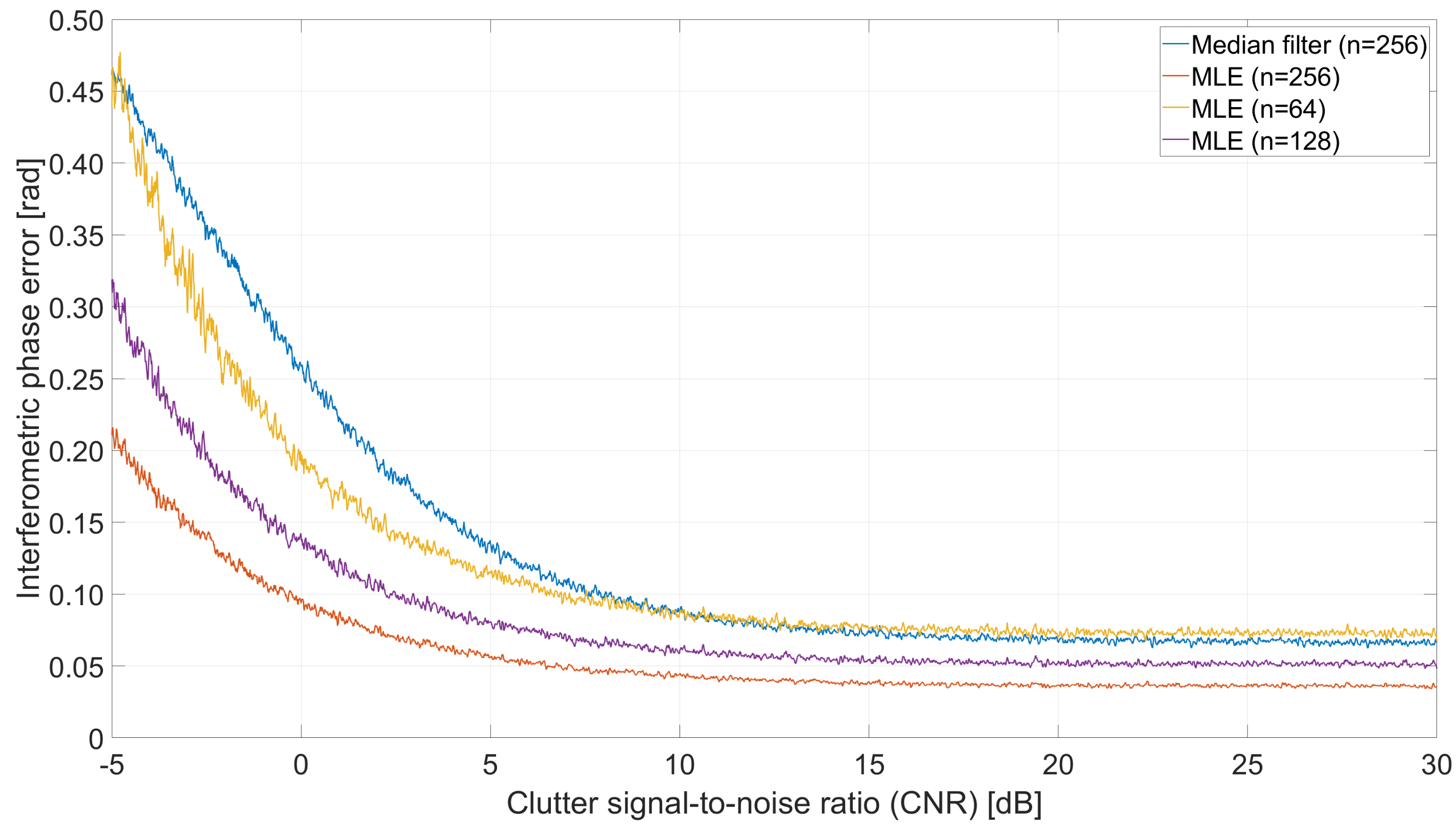
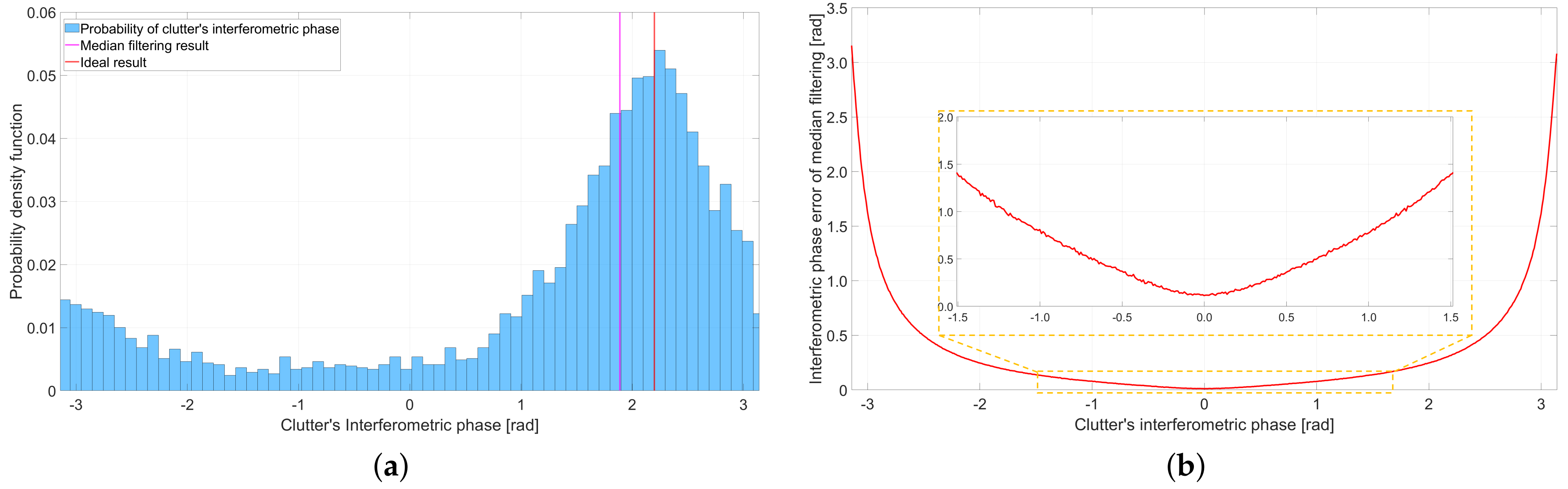
  • We evaluate the strengths and limitations of the LS algorithm and median filter algorithm in estimating the clutter’s interferometric phase of MA2DC algorithm and KB algorithm.
  • We propose an improved KB target relocation algorithm to maintain high accuracy while reducing sensitivity to the undesired phase errors. In the algorithm, we first employ the RANSAC algorithm to eliminate the outliers and then utilize the remaining accurate interferometric phase for relocating moving targets. The experimental results demonstrate that the proposed algorithm can indeed improve the accuracy of moving target relocation.
The remainder of the article is organized as follows. The target relocation model is constructed in Section 2. Then, in Section 3, the expression of the interferometric phase error caused by the isolated strong reflectors is derived, and an improved moving target relocation framework is proposed in detail. Section 4 presents the simulated and real data results in moving target relocation. The conclusions of this paper are presented in Section 5.

2. Relocation Signal Model Analysis

2.1. Moving Target Relocation Model

The geometry of an UAV-borne GMTI radar system with two channels along the flight direction is shown in Figure 1. The X-axis represents the flight direction of the UAV, the Y-axis is perpendicular to the flight direction on the ground, and the Z-axis points upwards towards the sky. In the GMTI radar system, the first channel serves as both the transmitting (TX) and receiving (RX) channel, defined as channel 0, and the second channel only serves as the receiving channel, defined as channel 1. The channel distance between the two channels is d. At the time t = 0 , the coordinates of the UAV platform are ( 0 , 0 , H ) , and the velocity vector is v = ( 0 , 0 , v ) . On the ground, there is a moving target p whose coordinates are ( x p , y p , 0 ) with a velocity vector v p = ( v p x , v p y , 0 ) .
Suppose that the GMTI radar system uses the linear frequency modulation (LFM) signal, which is given by
s ( τ ) = rect ( τ T p ) exp [ j ( 2 π f c τ + k π τ 2 ) ] ,
where rect denotes the rectangle window, τ denotes the radar fast time, f c denotes the carrier frequency, k denotes the LFM rate, and T p denotes the pulse width. After range compression, the received signal of target p in two channels is
(2) s p , 0 ( τ , t ) = ω a ( t ) sinc [ B ( τ 2 R p , 0 ( t ) c ) ] exp ( j 2 π 2 R p , 0 ( t ) λ ) (3) s p , 1 ( τ , t ) = ω a ( t ) sinc [ B ( τ R p , 0 ( t ) + R p , 1 ( t ) c ) ] exp ( j 2 π R p , 0 ( t ) + R p , 1 ( t ) λ ) ,
where ω a ( t ) represents the antenna window function, t represents the radar slow time, B represents the signal bandwidth, c represents the speed of light, and λ represents the wavelength. R p . 0 ( t ) and R p . 1 ( t ) are the slant range between the receiving channels and the moving target p. According to the second-order Taylor series expansion, R p . 0 ( t ) and R p . 1 ( t ) can be expressed as
R p , 0 ( t ) = ( x p v t + v p x t ) 2 + ( y p + v p y t ) 2 + H 2 R 0 + x p ( v p x v ) t + y p v p y t R 0 = R 0 + v p , r t
R p , 1 ( t ) = ( x p v t + v p x t d ) 2 + ( y p + v p y t ) 2 + H 2 R 0 + x p ( v p x v ) t + y p v p y t R 0 x p d R 0 = R 0 + v p , r t x p d R 0 ,
where R 0 = x p 2 + y p 2 + H 2 is the slant range at t = 0 , and v p , r = ( x p ( v p x v ) + y p v p y ) / R 0 is the relative radial velocity between the UAV and the moving target p. Since the difference term x p d / R 0 between the R p . 0 ( t ) and R p . 1 ( t ) is much smaller than the range resolution, the term sinc [ B ( τ ( R p , 0 ( t ) + R p , 1 ( t ) ) / λ ) ] is approximately equal to the term sinc [ B ( τ 2 R p , 0 ( t ) / λ ) ] . Hence, the received signals of target p are in the same range bin in channel 0 and channel 1.
After the azimuth fast Fourier transform (FFT), the received signals can be expressed as
(6) I p , 0 ( τ , f a z ) = A sinc [ B ( τ 2 R p , 0 ( t ) c ) ] δ ( f a z 2 v p , r λ ) (7) I p , 1 ( τ , f a z ) = A sinc [ B ( τ 2 R p , 0 ( t ) c ) ] δ ( f a z 2 v p , r λ ) exp ( j 2 π x p d λ R 0 ) .
Due to the relative radial velocity v p , r of the moving target p, the Doppler frequency f a z = 2 v p , r λ does not correspond to the target’s position x p in the azimuth direction. Fortunately, the interferometric phase φ p between the received signals of the two channels is not affected by the velocity v p , r , which can be expressed as
φ p = arg ( I p , 0 I p , 1 * ) = 2 π x p d λ R 0 ,
where [ · ] * denotes the complex conjugate operation. In Equation (8), the term ( x p d ) / ( λ R 0 ) is related to the direction of arrival (DOA) angle θ p , which can be used to estimate the position of moving target p in the azimuth direction.
However, the above derivation is based on ideal conditions. In reality, the antennae can deviate from the flight direction of the UAV due to the influence of atmospheric turbulence, flight attitude, and other factors. Thus, the channel distance vector d of the two receiving channels should be expressed as d = ( d x , d y , d z ) , and the channel distance d = d x 2 + d y 2 + d z 2 . Figure 2 illustrates the geometry of the GMTI radar system in reality.
In addition, the amplitude error and phase error of the dual-channel system must be introduced to the signal model. Therefore, the received signals of the moving target p between two channels in real conditions can be expressed as
(9) I p , 0 ( τ , f a z ) = A 0 e x p ( j φ 0 ) sinc [ B ( τ 2 R p , 0 ( t ) c ) ] δ ( f a z 2 v p , r λ ) (10) I p , 1 ( τ , f a z ) = A 1 e x p ( j φ 1 ) sinc [ B ( τ 2 R p , 0 ( t ) c ) ] δ ( f a z 2 v p , r λ ) exp ( j 2 π x p d x + y p d y H d z λ R 0 ) .
where A i and e x p ( j φ i ) are the amplitude error and phase error for the ith channel. Therefore, the interferometric phase φ p of the clutter is
φ p = arg ( I p , 0 I p , 1 * ) = 2 π ( x p d x + y p d y H d z ) λ R 0 ( φ 1 φ 0 ) .
Compared with the interferometric phase in Equation (8), the interferometric phase error x p ( d d x ) λ R 0 is caused by the actual along-track channel distance d x deviating from its ideal value d, the interferometric phase error y p d y H d z λ R 0 is caused by the across-track channel distance error due to a non-ideal radar flight path, flight attitude, and other reasons, and the interferometric phase error φ 1 φ 0 is caused by the radar system. Figure 3 illustrates the azimuth position error caused by the terms x p ( d d x ) λ R 0 and y p d y H d z λ R 0 . In this example, the parameters are set as R 0 = 3 km, λ = 1.76 cm, d = 17 cm, and H = 800 m. From Figure 3, it can be seen that the azimuth position error of the moving target can be more than 20 m and 40 m if the terms x p ( d d x ) λ R 0 and y p d y H d z λ R 0 are not compensated. Therefore, compensating for these interferometric phase errors is necessary in the moving target relocation method.

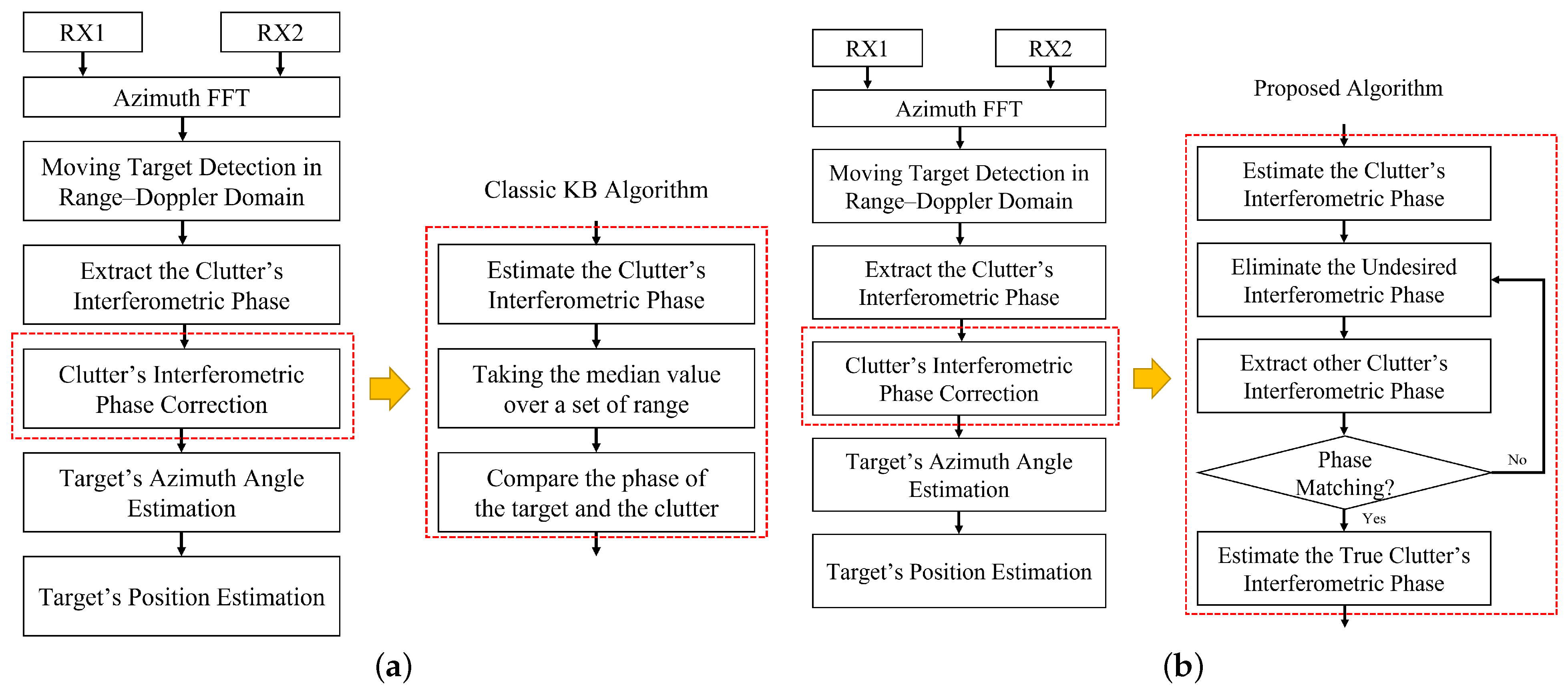
2.2. The Classic Knowledge-Based Target Relocation Algorithm

To compensate for the phase errors, the KB target relocation algorithm proposed in [27] used the moving target’s neighboring clutter to estimate the target’s azimuth position. In the KB algorithm, the received ground clutter signals around target p between two channels can be expressed as
I c , 0 ( τ , f a z ) = A 0 e x p ( j φ 0 ) sinc [ B ( τ 2 R p , 0 ( t ) c ) ] δ ( f a z 2 v x p λ R 0 )
I c , 0 ( τ , f a z ) = A 1 e x p ( j φ 1 ) sinc [ B ( τ 2 R p , 0 ( t ) c ) ] δ ( f a z 2 v x p λ R 0 ) exp ( j 2 π x p d x + y p d y H d z λ R 0 ) .
The interferometric phase φ c of the clutter is
φ c = arg ( I c , 0 I c , 1 * ) = 2 π ( x p d x + y p d y H d z ) λ R 0 ( φ 1 φ 0 ) .
Comparing the Equations (11) and (14), the moving target and its neighboring clutter have the same interferometric phase. Thus, the azimuth position of the detected moving target can be estimated by searching the main-lobe clutter region to find a Doppler frequency for which the clutter’s interferometric phase is closest to the measured interferometric phase of the considered moving target. However, affected by the system’s thermal noise, the actual received ground clutter signals are different from the values in Equations (12) and (13).
The clutter signals in the received channels can be modeled as [20]
(15) I 0 = A 0 + N 0 (16) I 1 = A 1 exp ( j φ 0 ) + N 1 ,
where I i is the clutter signal of the radar received channel, A i is the complex magnitude of the clutter signal, and N i is the thermal noise power. It is well known that A i is the circular Gaussian random variable with zero mean and the same mean variance σ c , and N i is the additive circular Gaussian white noise with zero mean and σ n variance. The correlation coefficient γ between the two channels is given by [20]
γ = E [ I 0 I 1 * ] E [ | I 0 | 2 ] E [ | I 1 | 2 ] = | γ c | 1 + CNR 1 ,
where CNR = σ c 2 / σ n 2 is the clutter signal-to-noise ratio, and γ c is called the clutter coherence, which represents the correlation between the two channel signals.
The probability density function (pdf) of the interferometric phase can be expressed as
pdf ( φ ) = 1 | γ | 2 2 π 1 1 β 2 { 1 + β arccos ( β ) 1 β 2 } ,
where β = | γ | cos ( φ φ 0 ) . Figure 4 illustrates different plots of the interferometric phase pdf for different correlation coefficients γ . It is obvious that the higher the CNR is, the more the pdf of the interference phase concentrates to the true phase value φ 0 [45]. When γ = 1 , the pdf of the interference phase becomes a Dirac delta function.
To increase the CNR, the most common method is to use the MLE algorithm, which uses a set of range bins and can be expressed as
φ ( f ^ d k ) = arg { n = 1 N I 0 ( R n , f ^ d k ) I * ( R n , f ^ d k ) } ,
where f d k is the kth Doppler frequency cell, and N is the number of range bins. If the phase value is limited to φ 0 π and φ 0 + π , then the standard deviation σ φ of this phase estimate for different N can be numerically computed, as shown in Figure 5 [46].
The Cramér–Rao bound (CRB) [46] for the σ φ in the MLE algorithm is
σ φ = 1 γ 2 2 N γ 2 .
The σ φ approaches this bound when N . Therefore, in order to improve the accuracy of the interferometric phase estimation, many range bins should be taken.

3. Moving Target Relocation with Undesired Phase Error

3.1. Undesired Phase Error Signal Model

The analysis in Section 2.2 assumes that the clutter is uniform in the site. Unfortunately, the estimated interferometric phase of clutter usually suffers from strong isolated targets such as tall buildings, slowly moving targets, and so on. The interferometric phases of these targets are different from the uniform clutter’s statistical result, which is in conflict with the uniform assumption. Thus, the moving target relocation method should eliminate these outliers.
The signals of these isolated targets in received channels 0 and 1 can be rewritten as
(21) I e , 0 ( τ , f d ) = A sin c ( B ( τ 2 c R e , 0 ( t ) ) ) δ ( f d 2 v e x e λ R e , 0 ( t ) )   I e , 1 ( τ , f d ) = A sin c ( B ( τ 2 c R e , 0 ( t ) ) ) δ ( f d 2 v e x e λ R e , 0 ( t ) )
exp ( j 2 π ( d x x e + d y y e d z ( H z e ) ) λ R e , 0 ( t ) ) ,
where z p is the height of the targets, and v e is the radial velocity of the targets. In the maximum likelihood estimator (MLE) algorithm, the estimation of the clutter’s interferometric phase will be rewritten as
φ ( f ^ d ) = arg { n 1 N I 0 ( R n , f d ) I 1 * ( R n , f d ) + I e , 0 ( R e , f d ) I e , 1 * ( R e , f d ) } .
Then, an undesired phase error is introduced to the estimation of the clutter’s interferometric phase, which can be expressed as
φ = φ 0 + φ n o i s e + Δ φ .
Figure 6 illustrates the error in the MLE algorithm caused by the undesired target at different SNRs to the different CNRs of the clutter. In the example, the number of range bins is 64, and the interferometric phase of the undesired target φ e = arg ( I e , 0 I e , 1 * ) = 0.5 π . The example shows that these strong isolated targets can cause a significant error in the estimation of the clutter’s interferometric phase.
To solve this issue, the classic KB algorithm uses the median filter algorithm to filter out the interferometric phase error. The principle of the median filtering algorithm can be expressed as
φ ( f d k ) = Med R n { φ ˜ ( f d k , R n ) , n = 1 , 2 , , N } , k = 1 , 2 , K .
When an undesired interferometric phase is caused by the undesired signal in the scene (as shown in Figure 7), the median filter algorithm can easily filter it out.
Figure 8 illustrates the error in the median filter algorithm caused by the undesired target at different SNRs to the different CNRs of the clutter. Compared with the errors in Figure 6, the example shows that, with the use of the median filter algorithm, the clutter’s interferometric phase estimation is almost not affected by these undesired phase errors.
However, there are several shortcomings when using the median filter algorithm. First, according to Equation (25), the accuracy of the median filter algorithm is related to the CNR of each range bin. Hence, the performance of the median filter algorithm is worse than that of the MLE when there is no undesired phase error. Figure 9 illustrates a Monte Carlo experiment (times = 200) of the interferometric phase error estimation between the MLE algorithm and the median filter algorithm at different range bins. It can be seen that the number of range bins that the median filter algorithm required was three times more than that required by the MLE algorithm, which is a large challenge for GMTI radar systems.
In addition, the median filter algorithm also faces the issue of phase ambiguity. When the interferometric phase is not at 0 radians, the pdf of the clutter’s interferometric phase is no longer symmetrically between π and π . Figure 10 illustrates this phase error in the median filter algorithm. An example of the median filter algorithm estimation is shown in the Figure 10a, when the interferometric phase of the clutter is 0.7 π . According to the figure, there is a significant difference between the estimation result of the median filter algorithm (pink solid line) and the ideal result (red solid line). Further, Figure 10b shows the variation in the phase error with the clutter’s phase. In the figure, the phase error becomes non-negligible when the interferometric phase approaches π , which will degrade the performance of the median filter algorithm in interferometric phase estimation.

3.2. Proposed Improved Algorithm That Eliminates the Undesired Phase Error

As mentioned above, the MLE algorithm performs better in estimating the clutter’s interferometric phase but is sensitive to the undesired phase error. The median filter algorithm is insensitive to the undesired phase error, but its accuracy is lower than that of the MLE algorithm. Then, in the classic KB algorithm [27], the median filer algorithm is applied to solve the problem of outliers. The flowchart for the classic KB algorithm is shown in Figure 11a.
As a comparison, our proposed relocation algorithm takes strengths of both the MLE algorithm and the median filter algorithm. To explain our proposed algorithm, a simplified flowchart is shown in Figure 11b. Compared with the classic KB algorithm, the issue of the MLE algorithm being sensitive to the outliers has led us to increase the steps for eliminating outliers in the new flowchart.
As shown in Figure 11b, the range compression data RX1 and RX2 are first transformed into the range–Doppler (RD) domain via azimuth FFT. After that, the clutter suppression interference (CSI) [47] and cell-averaging constant false-alarm-rate (CA-CFAR) detector are implemented in the moving target detection block. Next, to relocate these detected moving targets, the clutter’s interferometric phase is extracted for each Doppler frequency within the main-lobe clutter, via the MLE algorithm.
Then, to eliminate the undesired phase errors, we first employed the RANSAC algorithm and LS algorithm to estimate the reference clutter’s interferometric phase. The estimate block can be divided into three main steps as follows.
  • First, we randomly select Q cells among the K azimuth Doppler frequency cells of the clutter’s interferometric phase. Then, the clutter’s interferometric phase can be estimated using the LS algorithm.
  • Next, we calculate the difference between the residual K-Q cells and the estimation and compare it with a threshold T 1 . If the difference is smaller than the threshold T 1 , then it is considered as a compatible cell and included in a set.
  • We repeat steps 1 and 2 for some predetermined number of iterations. Finally, we have the set that includes the most effective compatible cells, and we employ the LS algorithm to compute an improved estimation of the clutter’s interferometric phase.
After having estimated the reference clutter’s interferometric phase, the undesired phase error can be eliminated by a threshold T 2 = 3 σ c , and the other range bins will be used to re-extract the clutter’s interferometric phase. If the new estimation result does not match the reference phase, one can then repeat the above blocks and reduce the threshold T 2 until the phases are matched or until a predetermined number of iterations. Finally, the moving target can be relocated with the new clutter’s interferometric phase estimation.
Figure 12 illustrates how the proposed algorithm progressively improves the accuracy of the interferometric phase estimation. In the figure, the direct estimation results by the MLE algorithm are annotated by a green dashed line with x marks. It can be seen that there is a significant error between the results and the true value. Therefore, the direct LS estimation results in inadequate precision, yielding a mean misestimate error of 3.15 .
To eliminate these undesired phase errors, we employed the RANSAC algorithm, and the estimation results are annotated by the purple solid line. As a comparison, the mean misestimate error of the estimation with and without the RANSAC algorithm is Δ φ e r r o r = 2.30 . This misestimate error can introduce an azimuth position error σ x = Δ φ e r r o r λ R 2 π d x 2.24 m when the slant range R = 3000 m.
After matching the phase, the new clutter’s interferometric phase estimation results are annotated by the orange dashed line with cross marks. Compared to the old clutter’s interferometric phase, the re-extracted results (yellow solid line) are no longer affected by the phase error and demonstrate a result much closer to the ideal condition (red solid line), yielding a mean misestimate error of 0.92 .

4. Experimental Results

In this section, we describe the use of simulated dual-channel data and real data to evaluate the performance of the proposed algorithm. The real data were collected by an advanced UAV-borne dual-channel GMTI radar system with Ku-band, as shown in Figure 13. Table 1 shows the main parameters of the radar system. To ensure the validity of the comparison of the algorithms, the simulation parameters were the same as the real flight experiment parameters.

4.1. Comparison in the Simulated Experiment

In the simulated experiment, we used the signal model described in Section 2 to simulate the clutter signal. In the clutter, we also simulated six strong isolated targets, including three tall static targets and three moving targets, to show how the clutter interferometric phase deviated from its normal value due to these isolated targets. Figure 14 shows the range–Doppler image of the simulated experiment.
Figure 15 illustrates the estimation of the interferometric phase in the RD image. According to the figure, it can be seen that the interferometric phase estimations based on the MLE algorithm at the Doppler frequencies, which are the same Doppler frequency as the tall static targets, deviated from the normal value. As the comparison, the interferometric phase estimations based on the median filter algorithm were less affected by these undesired phase errors, but the accuracy of the estimations based on the median filter at other Doppler frequencies was lower than the accuracy of the estimations based on the MLE algorithm.
Figure 16 illustrates the comparison of our proposed algorithm with the LS algorithm, classic KB algorithm, classic KB + RANSAC algorithm, MA2DC algorithm, and ideal result. The result of the LS algorithm in the clutter’s interferometric phase based on the MLE algorithm has a large error compared with the ideal result due to the outliers. Although the clutter’s interferometric phase based on the median filter algorithm can filter the outliers, the result of the classic KB algorithm still has an error compared with the ideal result, due to the low CNR. As for the result of the MA2DC algorithm, since the algorithm directly estimates the clutter interferometric phase from the receiving data, strong reflectivity in the area can significantly affect the estimation accuracy. Thus, the result of the MA2DC has the largest error compared with the ideal result. In our proposed algorithm, after applying the RANSAC algorithm to eliminate these outliers, the result overlaps quite well with the ideal estimation of the clutter’s interferometric phase.
In addition, we also evaluated the performance of our proposed algorithm by calculating the relocation position errors of three moving targets in the RD image: MT1, MT2, and MT3. The mean position errors of the algorithms are shown in Table 2. It can be seen that the relocation position errors of our proposed algorithm in three moving targets are less than 1 m, which are lower than those of other algorithms. Therefore, our proposed algorithm shows the strongest performance in moving target relocation.

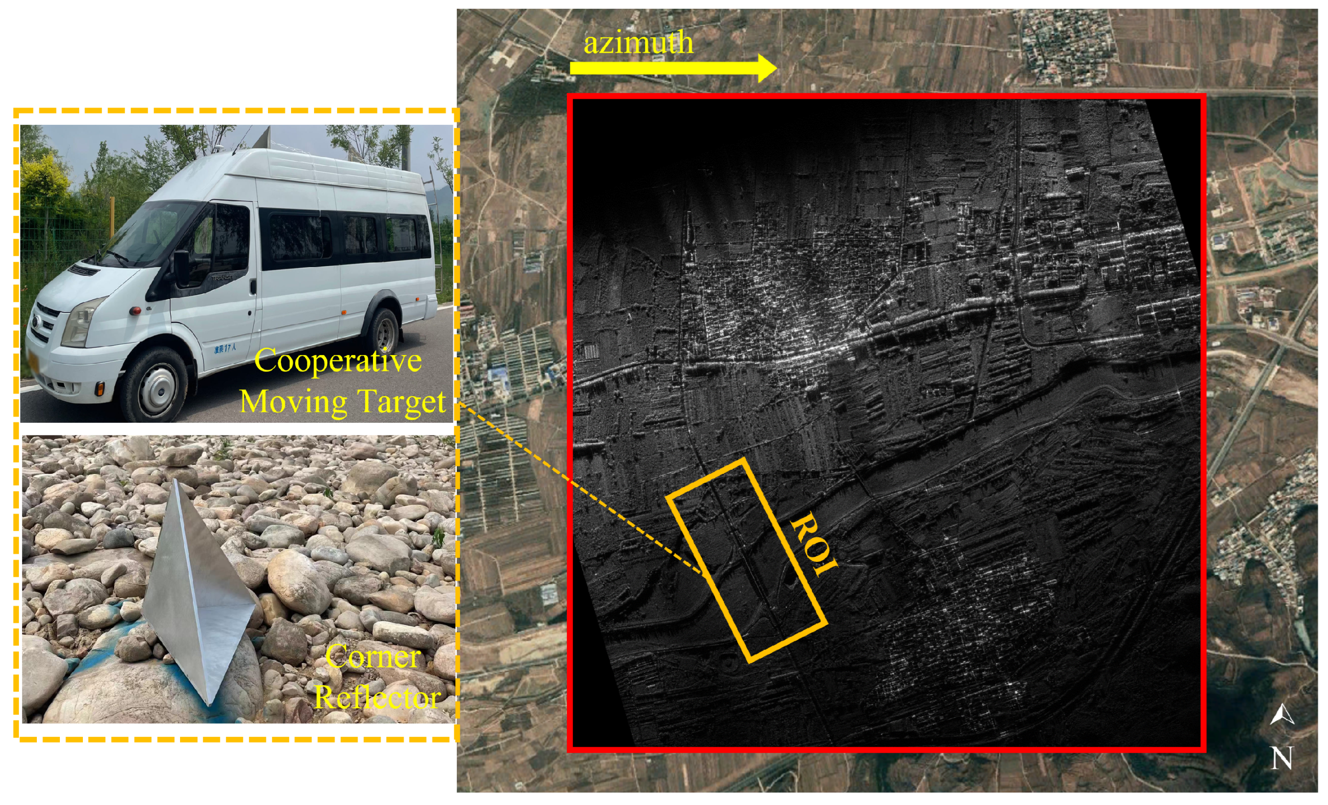
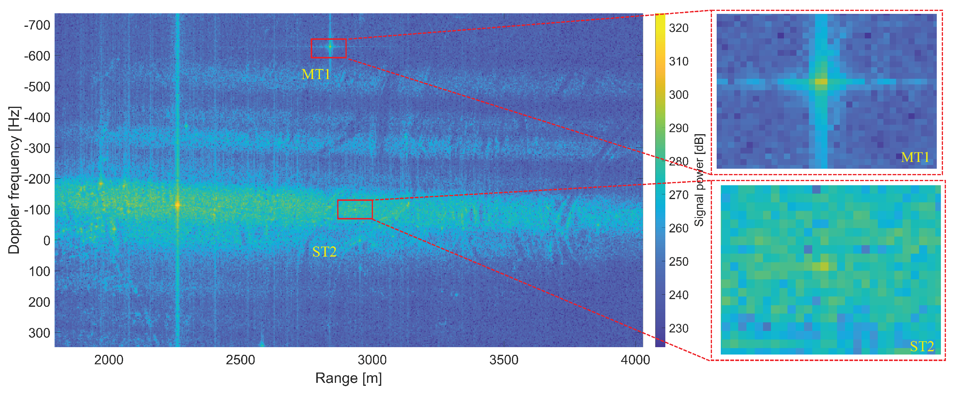
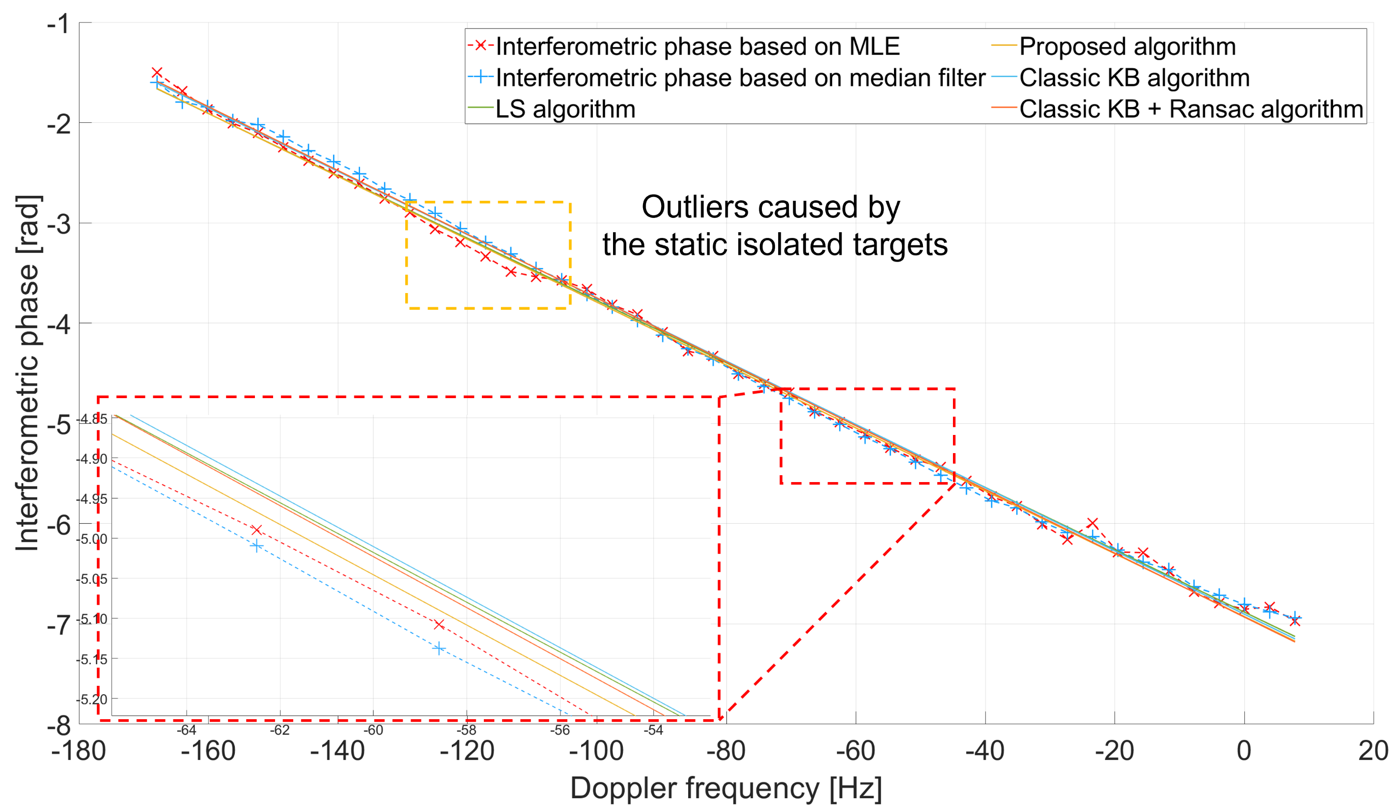
4.2. Comparison in a Real Experiment

In the real experiment, the flight was conducted in June 2022 over Beijing Pinggu, China. Figure 17 shows the image of the test site. A cooperative car MT1 and a corner reflector ST2 were located in the region of interest (ROI). The position of the corner reflector and the track of the cooperative car were recorded using handheld GPS devices. Here, the corner reflector was used to correct the position error caused by the platform.
Figure 18 shows the RD image and the enlarged images of MT1 and ST2, both within red boxes. In the figure, there are a few strong discrete targets in the RD image, which will affect the accuracy estimation of the interferometric phase between the two channels.
The estimation results of the interferometric phase based on the MLE algorithm (red dashed line with x markers) and the median filter algorithm (blue dashed line with cross markers) of this RD image are shown in Figure 19. The estimation results based on the MLE algorithm among the Doppler frequency −115 Hz do not match the rest due to the static isolated targets shown in Figure 18. Therefore, the direct LS estimation results (green solid line) in inadequate precision, and the estimation results of our proposed algorithm (yellow solid line) are less affected by these outliers. As a comparison, we also evaluated the performance of the classic KB algorithm (blue solid line) and KB + RANSAC algorithm (orange solid line). Since the interferometric phase estimations based on the median filter are less affected by the outliers, both algorithms achieve similar phase estimation accuracy.
Finally, we calculated the position of MT1. Figure 20 shows the absolute relocation position errors of the MT1 between the LS algorithm in MLE, the classic KB algorithm, the classic KB + RANSAC algorithm, the MA2DC algorithm, and our proposed algorithm.
The mean position errors of these algorithms are presented in Table 3. The absolute position errors of our proposed algorithm were usually less than or equal to the others. In addition, our proposed algorithm had a 75.99 % , 71.95 % , 31.25 % , and 67.68 % position accuracy improvement compared with the LS algorithm, classic KB algorithm, classic KB + RANSAC algorithm, and MA2DC algorithm, respectively. It is concluded that the proposed method can be considered an improvement in moving target relocation, especially when there are tall static targets and slowly moving targets in the test site.
Furthermore, to fully demonstrate the validity and superiority of our proposed algorithm, we have designed the test using urban area data based on the real experiment. Figure 21 illustrates the range–Doppler and the optical image of the urban area.
However, since there are no cooperative moving targets in the tested urban area, we decided to evaluate the performance of the proposed algorithm by comparing the accuracy of clutter interferometric phase estimation between the urban and the flat areas. The comparative results are shown in Figure 22. According to the figure, compared with direct using LS algorithm, the estimation accuracy of our proposed algorithm in the urban area is much closer to the estimation result in the flat area. Therefore, our proposed algorithm has shown its validity and superiority in the urban area.

5. Discussion

Our proposed improved KB relocation algorithm demonstrates great improvement in the accuracy of moving target relocation for UAV-borne GMTI systems. We first analyzed the undesired interferometric phase error in the moving target relocation model. Next, we analyzed the advantages and limitations of the MLE algorithm and the classic KB algorithm. To take the strengths of both algorithms, we first employ a two-stage RANSAC-LS pipeline. The integration of RANSAC algorithm with the LS algorithm can effectively eliminate the outliers caused by isolated reflectors (e.g., tall buildings) in the MLE algorithm.
The performance of the proposed algorithm has been verified using simulated data and real data. In the simulated experiment, the absolute position error of our proposed algorithm showed 94.00 % , 70.32 % , 51.19 % , and 96.85 % position accuracy improvement compared with the LS algorithm in MLE, the classic KB algorithm, the classic KB + RANSAC algorithm, and the MA2DC algorithm. In the real experiment, the absolute position error of our proposed algorithm showed 75.99 % , 71.95 % , 31.25 % , and 67.68 % position accuracy improvement compared with these algorithms. In addition, we also evaluate the performance of the proposed algorithm in the urban area, and the difference between the estimation result of our proposed algorithm in urban area and in flat area is negligible. The experiment aligns with the prior studies showing the improvement of proposed algorithm in addressing the interferometric phase errors for moving target relocation.
Despite the advantages, the main limitation of the proposed algorithm is that the predefined thresholds T 1 and T 2 in the RANSAC algorithm may fail in complex terrains (e.g., mountainous areas or urban areas with numerous high-rise buildings). In addition, the iterative extracting the clutter’s interferometric phase in RANSAC is time-consuming for the edge-device UAV-borne GMTI radar systems, which introduces additional complexity to real-time GMTI systems.
Hence, in our future work, we will focus on solving the limitations and challenges of the proposed algorithm. We plan to evaluate our algorithm in more terrains to develop adaptive thresholding in the RANSAC algorithm. Furthermore, an onboard hardware acceleration (e.g., FPGA) would also be designed to reduce the latency and improve the relocation performance.

6. Conclusions

In this article, we proposed an improved KB algorithm for UAV-borne GMTI radar systems, addressing the issue of the undesired phase errors caused by isolated strong reflectors (e.g., tall buildings). The key innovation of our proposed algorithm is to integrate the RANSAC algorithm with MLE algorithm to iteratively filter outliers and enhance interferometric phase estimation accuracy. Additionally, the performance of the proposed algorithm was verified using simulated data and real data. The experiments demonstrate that the proposed algorithm significantly outperforms the classic KB algorithm and the MA2DC algorithm. Our proposed algorithm shows high robustness and good performance in the moving target relocation procedure of the GMTI radar system. Therefore, the implementation of the proposed algorithm in lightweight UAV platforms can provide high-accuracy moving target relocation without high-precision INSs.

Author Contributions

Conceptualization, W.L., X.L., X.B. and Y.L. (Yanlei Li); methodology, W.L.; software, W.L. and Y.L. (Yunlong Liu); validation, W.L., Y.L. (Yanlei Li) and Y.L. (Yunlong Liu); formal analysis, W.L. and Y.Z.; investigation, W.L. and Y.Z.; resources, X.L.; data curation, W.L., X.B., Y.L. (Yunlong Liu) and X.G.; writing—original draft preparation, W.L.; writing—review and editing, W.L., Y.Z., Y.L. (Yanlei Li) and X.L.; visualization, W.L.; supervision, X.L.; project administration, X.L.; funding acquisition, X.B., Y.L. (Yanlei Li) and X.L. All authors have read and agreed to the published version of the manuscript.

Funding

This research received no external funding.

Institutional Review Board Statement

Not applicable.

Informed Consent Statement

Not applicable.

Data Availability Statement

The data presented in this study are available on request from the corresponding author.

Conflicts of Interest

The authors declare no conflicts of interest.

Abbreviations

The following abbreviations are used in this manuscript:
GMTIGround moving target indication
UAVUnmanned aerial vehicle
KBKnowledge-based
RANSACRandom sample sonsensus
INSInertial navigational systems
DCBDigital channel balancing
SNRSignal-to-noise ratio
KA-GMTRKnowledge-aided ground moving target relocation
A2DCAdaptive 2-D calibration
MA2DCModified adaptive 2-D calibration
LSLeast squares
MLEMaximum likelihood estimator
LFMLinear frequency modulation
DOADirection of arrival
CNRClutter-to-noise ratio
FFTFast Fourier transform
pdfProbability density function
CRBCramér–Rao bound
RDRange–Doppler
CSIClutter suppression interference
CA-CFAR  Cell-averaging constant false alarm rate
ROIRegion of interest

References

  1. Entzminger, J.N.; Fowler, C.A.; Kenneally, W.J. JointSTARS and GMTI: Past, present and future. IEEE Trans. Aerosp. Electron. Syst. 1999, 35, 748–761. [Google Scholar] [CrossRef]
  2. Chang, C.Y.; Woo, A.; Forry, H.; Sherman, J.; Recht, M.; Clark, R.; Levin, R. HISAR-300: An Advanced Airborne Multi-Mission Surveillance Radar. In Proceedings of the 2019 IEEE Radar Conference (RadarConf), Boston, MA, USA, 22–26 April 2019; pp. 1–6. [Google Scholar]
  3. Greenspan, M. Joint STARS—The Start of 50 Years of All Speed Surface Moving Target Detection and Tracking. IEEE Aerosp. Electron. Syst. Mag. 2023, 38, 32–37. [Google Scholar] [CrossRef]
  4. Cerutti-Maori, D.; Klare, J.; Brenner, A.R.; Ender, J.H.G. Wide-Area Traffic Monitoring with the SAR/GMTI System PAMIR. IEEE Trans. Geosci. Remote Sens. 2008, 46, 3019–3030. [Google Scholar] [CrossRef]
  5. Wang, B.; Song, C.; Liu, N.; Liu, Z.; Zhou, L.; Xiang, M. An Advanced Lightweight Dual-Band Digital Array SAR System: Earth Observation Imaging and Moving Target Detection. IEEE Sens. J. 2023, 23, 21776–21786. [Google Scholar] [CrossRef]
  6. Mosito, K.E.; Nel, W.A.J.; Blaauw, C.; Gaffar, Y.A.; de Witt, J.J. Detection, Tracking and Geo-location of Moving Targets in Airborne Radar Data using a DPCA GMTI Technique. In Proceedings of the 2022 IEEE Radar Conference (RadarConf22), New York, NY, USA, 21–25 March 2022; pp. 1–6. [Google Scholar]
  7. Li, X.; Wang, R.; Liang, G.; Yang, Z. A Multi-Objective Intelligent Optimization Method for Sensor Array Optimization in Distributed SAR-GMTI Radar Systems. Remote Sens. 2024, 16, 3041. [Google Scholar] [CrossRef]
  8. Kanistras, K.; Martins, G.; Rutherford, M.J.; Valavanis, K.P. A survey of unmanned aerial vehicles (UAVs) for traffic monitoring. In Proceedings of the 2013 International Conference on Unmanned Aircraft Systems (ICUAS), Atlanta, GA, USA, 28–31 May 2013; pp. 221–234. [Google Scholar]
  9. Otten, M.; Maas, N.; Bolt, R.; Caro-Cuenca, M.; Medenblik, H. Circular Micro-SAR for mini-UAV. In Proceedings of the 2018 15th European Radar Conference (EuRAD), Madrid, Spain, 26–28 September 2018; pp. 321–324. [Google Scholar]
  10. Jiang, S.; Cao, Y.; Luo, Y.; Guo, S.; Zhou, X.; Wang, X.; Zhang, S. Realization of dual-channel GMTI real-time processing technology based on FPGA. IET Conf. Proc. 2024, 2023, 1284–1289. [Google Scholar] [CrossRef]
  11. Criollo, L.; Mena-Arciniega, C.; Xing, S. Classification, military applications, and opportunities of unmanned aerial vehicles. Aviation 2024, 28, 115–127. [Google Scholar] [CrossRef]
  12. Cerutti-Maori, D.; Sikaneta, I. A Generalization of DPCA Processing for Multichannel SAR/GMTI Radars. IEEE Trans. Geosci. Remote Sens. 2013, 51, 560–572. [Google Scholar] [CrossRef]
  13. Chapin, E.; Chen, C.W. Airborne along-track interferometry for GMTI. IEEE Aerosp. Electron. Syst. Mag. 2009, 24, 13–18. [Google Scholar] [CrossRef]
  14. Wang, L.; Li, Y.; Wang, W.; An, D. Moving Target Indication for Dual-Channel Circular SAR/GMTI Systems. Sensors 2019, 20, 158. [Google Scholar] [CrossRef]
  15. Melvin, W.L. A STAP overview. IEEE Aerosp. Electron. Syst. Mag. 2004, 19, 19–35. [Google Scholar] [CrossRef]
  16. Yang, D.; Yang, X.; Liao, G.; Zhu, S. Strong Clutter Suppression via RPCA in Multichannel SAR/GMTI System. IEEE Geosci. Remote Sens. Lett. 2015, 12, 2237–2241. [Google Scholar] [CrossRef]
  17. Melvin, W.L.; Guerci, J.R. Knowledge-aided signal processing: A new paradigm for radar and other advanced sensors. IEEE Trans. Aerosp. Electron. Syst. 2006, 42, 983–996. [Google Scholar] [CrossRef]
  18. Riedl, M.; Potter, L.C. Knowledge-Aided Bayesian Space-Time Adaptive Processing. IEEE Trans. Aerosp. Electron. Syst. 2018, 54, 1850–1861. [Google Scholar] [CrossRef]
  19. Li, X.; Yang, Z.; Tan, X.; Liao, G.; Shu, Y. A Novel Knowledge-Aided Training Samples Selection Method for Terrain Clutter Suppression in Hybrid Baseline Radar Systems. IEEE Trans. Geosci. Remote Sens. 2022, 60, 1–16. [Google Scholar] [CrossRef]
  20. Budillon, A.; Pascazio, V.; Schirinzi, G. Estimation of Radial Velocity of Moving Targets by Along-Track Interferometric SAR Systems. IEEE Geosci. Remote Sens. Lett. 2008, 5, 349–353. [Google Scholar] [CrossRef]
  21. Wang, C.; Liao, G.; Zhang, Q. First Spaceborne SAR-GMTI Experimental Results for the Chinese Gaofen-3 Dual-Channel SAR Sensor. Sensors 2017, 17, 2683. [Google Scholar] [CrossRef]
  22. Huang, P.; Xia, X.-G.; Wang, L.; Xu, H.; Liu, X.; Liao, G.; Jiang, X. Imaging and Relocation for Extended Ground Moving Targets in Multichannel SAR-GMTI Systems. IEEE Trans. Geosci. Remote Sens. 2022, 60, 1–24. [Google Scholar] [CrossRef]
  23. Li, X.; Gao, W.; Han, X. Doppler beam sharpening/ground moving target indication techniques based on space–time adaptive processing for airborne active phased array fire-control radar. J. Eng. 2019, 2019, 6048–6051. [Google Scholar] [CrossRef]
  24. Jia, X.; Song, H. Clutter suppression for multichannel wide area surveillance system via a combination of STAP and RPCA. In Proceedings of the 2019 6th Asia-Pacific Conference on Synthetic Aperture Radar (APSAR), Xiamen, China, 26–29 November 2019; pp. 1–4. [Google Scholar]
  25. Zhao, Y.; Wang, J.; Song, F.; Wang, J.; Xu, J.; Zhou, M. Single-Channel SAR Moving Target Detection Method Based on RPCA. In Proceedings of the 2023 6th International Conference on Information Communication and Signal Processing (ICICSP), Xi’an, China, 23–25 September 2023; pp. 85–89. [Google Scholar]
  26. Deming, R.W.; MacIntosh, S.; Best, M. Three-channel processing for improved geo-location performance in SAR-based GMTI interferometry. In Proceedings of the Algorithms for Synthetic Aperture Radar Imagery XIX, Baltimore, MD, USA, 25–26 April 2012; p. 83940F-83940F-17. [Google Scholar]
  27. Ruixian, H.; Baochang, L.; Tong, W.; Dongdong, L.; Zheng, B. A Knowledge-Based Target Relocation Method for Wide-Area GMTI Mode. IEEE Geosci. Remote Sens. Lett. 2014, 11, 748–752. [Google Scholar] [CrossRef]
  28. Chen, H.; Wang, Z.; Gao, W.; Sun, H.; Lu, Y.; Li, Y. Knowledge-Aided Ground Moving Target Relocation for Airborne Dual-Channel Wide-Area Radar by Exploiting the Antenna Pattern Information. Remote Sens. 2021, 13, 4724. [Google Scholar] [CrossRef]
  29. Liu, K.; He, X.; Liao, G.; Zhu, S.; Tan, H.; Qiu, J. Multichannel SAR-GMTI Algorithm Based on Adaptive Data Reconstruction and Improved RPCA. IEEE Trans. Geosci. Remote Sens. 2025, 63, 1–16. [Google Scholar] [CrossRef]
  30. Klemm, R. Principles of Space-Time Adaptive Processing; IET: London, UK, 2006. [Google Scholar]
  31. Zhang, L.; Qiao, Z.; Xing, M.-d.; Yang, L.; Bao, Z. A Robust Motion Compensation Approach for UAV SAR Imagery. IEEE Trans. Geosci. Remote Sens. 2012, 50, 3202–3218. [Google Scholar] [CrossRef]
  32. Lei, Y.; Tong, W.; Zheng, B. Ground Moving Target Indication Using an InSAR System with a Hybrid Baseline. IEEE Geosci. Remote Sens. Lett. 2008, 5, 373–377. [Google Scholar] [CrossRef]
  33. Nickel, U. Overview of generalized monopulse estimation. IEEE Aerosp. Electron. Syst. Mag. 2006, 21, 27–56. [Google Scholar] [CrossRef]
  34. Gierull, C.H. Digital Channel Balancing of Along-Track Interferometric SAR Data; Defence R & D Canada-Ottawa: Ottawa, ON, Canada, 2003. [Google Scholar]
  35. Jäger, M.; Scheiber, R.; Reigber, A. Robust, Model-Based External Calibration of Multi-Channel Airborne SAR Sensors Using Range Compressed Raw Data. Remote Sens. 2019, 11, 2674. [Google Scholar] [CrossRef]
  36. Barros Cardoso da Silva, A.; Baumgartner, S.V.; de Almeida, F.Q.; Krieger, G. In-Flight Multichannel Calibration for Along-Track Interferometric Airborne Radar. IEEE Trans. Geosci. Remote Sens. 2021, 59, 3104–3121. [Google Scholar] [CrossRef]
  37. Han, S.; De Maio, A.; Carotenuto, V.; Pallotta, L.; Huang, X. Censoring Outliers in Radar Data: An Approximate ML Approach and its Analysis. IEEE Trans. Aerosp. Electron. Syst. 2019, 55, 534–546. [Google Scholar] [CrossRef]
  38. Chen, X.; Cheng, Y.; Wu, H.; Wang, H. Heterogeneous Clutter Suppression for Airborne Radar STAP Based on Matrix Manifolds. Remote Sens. 2021, 13, 3195. [Google Scholar] [CrossRef]
  39. Ge, B.; An, D.; Liu, J.; Feng, D.; Chen, L.; Zhou, Z. Modified Adaptive 2-D Calibration Algorithm for Airborne Multichannel SAR-GMTI. IEEE Geosci. Remote Sens. Lett. 2023, 20, 1–5. [Google Scholar] [CrossRef]
  40. Wang, Q.; Xue, B.; Hu, X.; Wu, G.; Zhao, W. Robust Space–Time Joint Sparse Processing Method with Airborne Active Array for Severely Inhomogeneous Clutter Suppression. Remote Sens. 2022, 14, 2647. [Google Scholar] [CrossRef]
  41. Barros Cardoso da Silva, A.; Joshi, S.K.; Baumgartner, S.V.; de Almeida, F.Q.; Krieger, G. Phase Correction for Accurate DOA Angle and Position Estimation of Ground-Moving Targets Using Multi-Channel Airborne Radar. IEEE Geosci. Remote Sens. Lett. 2022, 19, 1–5. [Google Scholar] [CrossRef]
  42. Seymour, M.S.; Cumming, I.G. Maximum likelihood estimation for SAR interferometry. In Proceedings of the IGARSS’94-1994 IEEE International Geoscience and Remote Sensing Symposium, Pasadena, CA, USA, 8–12 August 1994; Volume 2274, pp. 2272–2275. [Google Scholar]
  43. Candeias, A.L.B.; Mura, J.C.; Dutra, L.V.; Moreira, J.R. Interferogram phase noise reduction using morphological and modified median filters. In Proceedings of the 1995 International Geoscience and Remote Sensing Symposium, IGARSS ’95. Quantitative Remote Sensing for Science and Applications, Firenze, Italy, 10–14 July 1995; Volume 161, pp. 166–168. [Google Scholar]
  44. Fischler, M.A.; Bolles, R.C. Random sample consensus. Commun. ACM 1981, 24, 381–395. [Google Scholar] [CrossRef]
  45. Rosen, P.A.; Hensley, S.; Joughin, I.R.; Li, F.K.; Madsen, S.N.; Rodriguez, E.; Goldstein, R.M. Synthetic aperture radar interferometry. Proc. IEEE 2000, 88, 333–382. [Google Scholar] [CrossRef]
  46. Rodriguez, E.; Martin, J.M. Theory and design of interferometric synthetic aperture radars. IEE Proc. F (Radar Signal Process.) 1992, 139, 147–159. [Google Scholar]
  47. Yan, H.; Zheng, M.J.; Zhu, D.Y.; Wang, H.T.; Chang, W.S. A new approach to increase the two-dimensional detection probability of CSI algorithm for WAS-GMTI mode. Adv. Space Res. 2015, 56, 325–332. [Google Scholar] [CrossRef]
Figure 1. The geometry of the UAV-borne GMTI radar system and the moving target.
Remotesensing 17 01182 g001
Figure 2. The real geometry of the dual-channel GMTI radar system and the ground moving target.
Remotesensing 17 01182 g002
Figure 3. Illustration of the position error caused by the along-track and across-track channel distance errors. (a) Along-track channel distance error. (b) Across-track channel distance error (DoA angle θ = 10 ).
Remotesensing 17 01182 g003
Figure 4. Probability density functions of the clutter interferometric phase for different correlation coefficients γ .
Remotesensing 17 01182 g004
Figure 5. Standard deviation of the interferometric phase for different numbers of independent range bins N.
Remotesensing 17 01182 g005
Figure 6. The phase error in the MLE algorithm at different target signal-to-noise ratios (SNRs) and clutter signal-to-noise ratios (CNRs).
Remotesensing 17 01182 g006
Figure 7. Interferometric phase with undesired phase error. In the figure, the blue dots represent the estimation results of MLE algorithm in different range bins.
Remotesensing 17 01182 g007
Figure 8. The relationship between the error of median filter algorithm and target’s SNR and clutter’s CNR.
Remotesensing 17 01182 g008
Figure 9. Interferometric phase error estimation between the MLE algorithm and median filter algorithm at different range bins.
Remotesensing 17 01182 g009
Figure 10. Illustration of the phase error due to the phase ambiguity in the median filter algorithm. (a) The estimation error of the clutter’s interferometric phase when the interferometric phase of the clutter is 0.7 π ; (b) the variation in the phase error with the clutter’s phase.
Remotesensing 17 01182 g010
Figure 11. Simplified flowchart for the classic KB algorithm and proposed algorithm. The innovation of the proposed algorithm is to eliminate the undesired interferometric by using the random sample consensus (RANSAC) algorithm. (a) Classic KB algorithm; (b) proposed algorithm.
Remotesensing 17 01182 g011
Figure 12. The performance of our proposed algorithm in clutter’s interferometric phase estimation. The undesired errors are caused by two static targets, whose heights are 24 m and 12 m.
Remotesensing 17 01182 g012
Figure 13. The UAV-borne dual channel GMTI radar system.
Remotesensing 17 01182 g013
Figure 14. Range–Doppler image of the simulated experiment with three static targets and three moving targets.
Remotesensing 17 01182 g014
Figure 15. Clutter’s interferometric phase estimation based on the MLE and median filter of the simulated data.
Remotesensing 17 01182 g015
Figure 16. Estimation of the interferometric phase based on different algorithms.
Remotesensing 17 01182 g016
Figure 17. Experiment with a cooperative moving car. The car moved in the ROI (orange box), and its track was recorded using a handheld GPS device.
Remotesensing 17 01182 g017
Figure 18. Range–Doppler image of the real experiment in the test site.
Remotesensing 17 01182 g018
Figure 19. Comparisons of different algorithms in the interferometric phase estimation.
Remotesensing 17 01182 g019
Figure 20. Position errors of the cooperative moving target using different algorithms.
Remotesensing 17 01182 g020
Figure 21. Urban area in the real experiment: (a) Range–Doppler image of the real experiment within urban area; (b) optical image of the urban area.
Remotesensing 17 01182 g021
Figure 22. Estimation accuracy of the interferometric phase based on LS algorithm and proposed algorithm in urban area and flat area.
Remotesensing 17 01182 g022
Table 1. GMTI radar system parameters.
QuantitySymbolValue
Velocity of the platformv14 m/s
Number of Tx/Rx channels 1/2
Pulse repetition frequencyPRF2000 Hz
Range bandwidthBW40 MHz
Channel distance d a 0.17 m
Carrier frequency f c 17 GHz
Altitude of the platform h p l a t 800 m
Table 2. Mean position errors based on different algorithms of the simulated data.
AlgorithmMT1MT2MT3
LS algorithm10.1225 m9.3559 m9.5544 m
Classic KB algorithm2.7080 m1.6274 m1.7954 m
Classic KB + RANSAC algorithm1.1675 m1.1638 m1.2321 m
MA2DC algorithm19.3282 m18.0241 m17.9821 m
Proposed algorithm0.5886 m0.5467 m0.6041 m
Table 3. Mean position error using different algorithms.
MethodMean Position Error
LS algorithm in MLE17.4308 m
Classic KB algorithm14.9256 m
Classic KB + RANSAC algorithm6.0884 m
MA2DC algorithm12.9502 m
Proposed algorithm4.1860 m
Disclaimer/Publisher’s Note: The statements, opinions and data contained in all publications are solely those of the individual author(s) and contributor(s) and not of MDPI and/or the editor(s). MDPI and/or the editor(s) disclaim responsibility for any injury to people or property resulting from any ideas, methods, instructions or products referred to in the content.

