Article

Retrospective Spectrum-Conversion Method Based on Time-Modulated Van Atta Array

1
State Key Laboratory of Complex Electromagnetic Environment Effects on Electronics and Information System, College of Electronic Science and Technology, National University of Defense Technology, Changsha 410073, China
2
Unit 31648 of PLA, Nanning 530022, China
*
Author to whom correspondence should be addressed.
Remote Sens. 2025, 17(7), 1257; https://doi.org/10.3390/rs17071257
Submission received: 19 February 2025 / Revised: 30 March 2025 / Accepted: 31 March 2025 / Published: 2 April 2025

Abstract

:
Spectrum conversion is one of the important applications in the non-linear electromagnetic (EM) field, which is widely used in antennas, wireless communication, radar imaging, etc. However, controlling spectrum conversion with excellent retrospective characteristics at oblique incidence directions remains a major issue in microwave systems. In this paper, a time-modulated Van Atta array is proposed to manipulate the spectral distribution of the echo signal. The array prototype experiments are conducted to demonstrate the variation properties of the monostatic radar cross section (RCS) at oblique incidence directions. On this basis, the periodic modulation model of the retrospective signal is established for the time-modulated Van Atta array. Several discrete harmonic components are symmetrically distributed on both sides of the original spectra. The influence of modulation parameters on the generated harmonics is analyzed in detail. The array prototype experiment is carried out, and the variation characteristics of the monostatic RCS in the oblique incidence direction are verified.

1. Introduction

Spectrum conversion is usually observed in natural materials interacting with electromagnetic (EM) waves from microwave to optical frequencies as a typical electromagnetic non-linear phenomenon. Such phenomena are generally associated with dielectric polarization responding in a non-linear way to the incident field intensity, causing the radiated field to oscillate at a new frequency. These spectrum-conversion phenomena has offered a diverse range of applications from communication to sensing [1,2,3,4,5,6,7,8,9].
In recent years, many experts have gradually begun to conduct in-depth and systematic research on the spectrum-conversion phenomenon. As a reported method, phase-switched surface (PSS) [10,11] imposes phase modulation onto the radar reflected-signal through intermittent on–off control of the active impedance layer. As a result, EM wave energy is redistributed into the generated harmonics with none remaining at the original incident carrier frequency. These harmonics are located outside the passband of the radar receiver, which is widely applied in the radar stealth [12,13]. X. Fang [14] proposed a self-adaptive retro-reflective planar Doppler cloak composed of a pair of space-time-modulated metasurfaces, which can perform frequency conversion. The first metasurface focuses the incident field in a specific location on the second metasurface, which is designed for enabling retro-reflection and Doppler frequency shift compensation. Adaptive Doppler stealth can improve the undetectability of invisible moving objects. L. Xu places the generated harmonics in the receiver passband and studies its radar matched filtering characteristics [15]. In addition, a time-modulated method based active frequency selective surface (AFSS) absorber/reflector [16,17,18] is proposed to modulate the radar signal [19,20,21,22,23]. The digital-coding control network is utilized to realize the predefined modulating function for spectrum conversion. On this basis, the imaging properties of the generated harmonic based on time-modulated AFSS are further investigated. The phenomenon of distance transformation and image defocusing are successively discovered [24,25]. However, the above method can only achieve EM wave modulation in the vertical direction due to the limitation of the mirror reflection mechanism. When the incident EM wave is at oblique incidence directions, the spectrum-conversion modulation effect will be significantly reduced.
In terms of harmonic modulation in wide-angle domain, researchers have proposed many feasible solutions. Y. Wang introduces a time-modulated reflector array (TMRA) to realize spectrum conversion in different angles. The structure can control the radiation pattern at both central and harmonic frequencies through multiple PIN diodes integrated into the array elements [26]. G. Y. Song [27] reports an acoustic planar retroreflector capable of effectively reflecting sound along its incident direction for a wide operating angle range (0−70°). Both the simulated and measured results provide evidence of the sound retroreflection effect. M. Feng [28] proposes a wide-angle flat corner reflector based on the multiple phase gradient modulated metasurface. Through designing the related gradient phase, the propagation direction of the reflected electromagnetic wave is just opposite to the propagation of the incidence wave based on the generalized version of the reflection law. This guaranteed a radar cross section (RCS) enhancement in the vicinity of this incidence direction. T Cui has performed extensive research on information metamaterials and metasurfaces [29]. A general space-time-modulated digital coding metasurface theory is proposed to achieve EM wave modulation in both frequency and space domains [30]. Each unit or column of units in the structure shares a bias voltage to obtain more precise control for propagation direction and harmonic energy distribution simultaneously. On this basis, a novel wireless communication system based on digital-coding metasurface is proposed to transmit real-time signals with excellent performance, which significantly simply the architecture of modern communication systems [31,32]. However, in the above method, the modulation system and manipulation schemes are complex because the pin diodes within the unequal unit or column are controlled by different waveform. At the same time, the prior information of the incoming wave often needs to be acquired to support the pointing of the reflected wave.
The Van Atta array is an excellent option to realize spectrum conversion in a wide-angle domain. It is a new beam adaptive passive antenna array based on phase conjugation technology [33,34], which has been widely used in target calibration, satellite communication, and radio frequency identification fields [35,36]. The array is simple in design and automatically reflects the incident EM wave toward the source direction without prior knowledge, so it can accurately achieve directional backscattering characteristics of incident waves at different angles [37]. At present, abundant research has been performed to obtain wide operating bandwidth and strong energy. Z. Miao [38] proposes the circular polarization characteristics of planar passive Van Atta arrays for vehicle radar applications. The designed array utilizes the baseband coaxial line as the feedback network, which can further expand the working bandwidth of the array. However, the above research on the array mainly focuses on its static EM properties, while the dynamic modulation effect on electromagnetic (EM) waves is rarely reported. K. Song [39] describes a retro-reflective Van Atta array to modulate radar signal in a large angle range. D. Ramaccia [40] reports experimental results on a completely passive antenna carpet device inspired by the retroreflector configuration of the Van Atta array. A large electric triangular bulge is designed on the ground plane, its sides covered by two conventional patch antenna arrays. The antennas are connected to each other in a Van Atta style connection, which ensures the recovery of the reflection angle and simulates the reflection of the ground plane at different lighting angles. A. Tobia [41] discusses a possible antenna-based cloak that uses a triangular bulge in one ground plane obscured by a pair of conventional half-wavelength dipole arrays. It simulates the reflection of the ground plane over the operating band of the antenna element frequency. Due to the adaptive characteristics of the proposed configuration, a wide angular bandwidth is achieved.
Inspired by the above ideas, a spectrum-conversion method with flexible harmonic modulation capability in oblique incidence direction is reported in this paper. The designed structure is a Van Atta array based on time modulation. On the basis of wide-angle backtracking characteristics, the on–off control of Van Atta array is realized in combination with electronically controlled microwave switching elements, and the dynamic modulation effect of EM wave is finally realized. The array structure includes eight columns of rectangular series resonant microstrip patch antenna elements, connected microstrip transmission lines, and single-pole single-throw (SPST) switches based on PIN diode. Excited by a rectangular pulse of bias signal, the array is able to intermittently switch between high-scattering and low-scattering states.

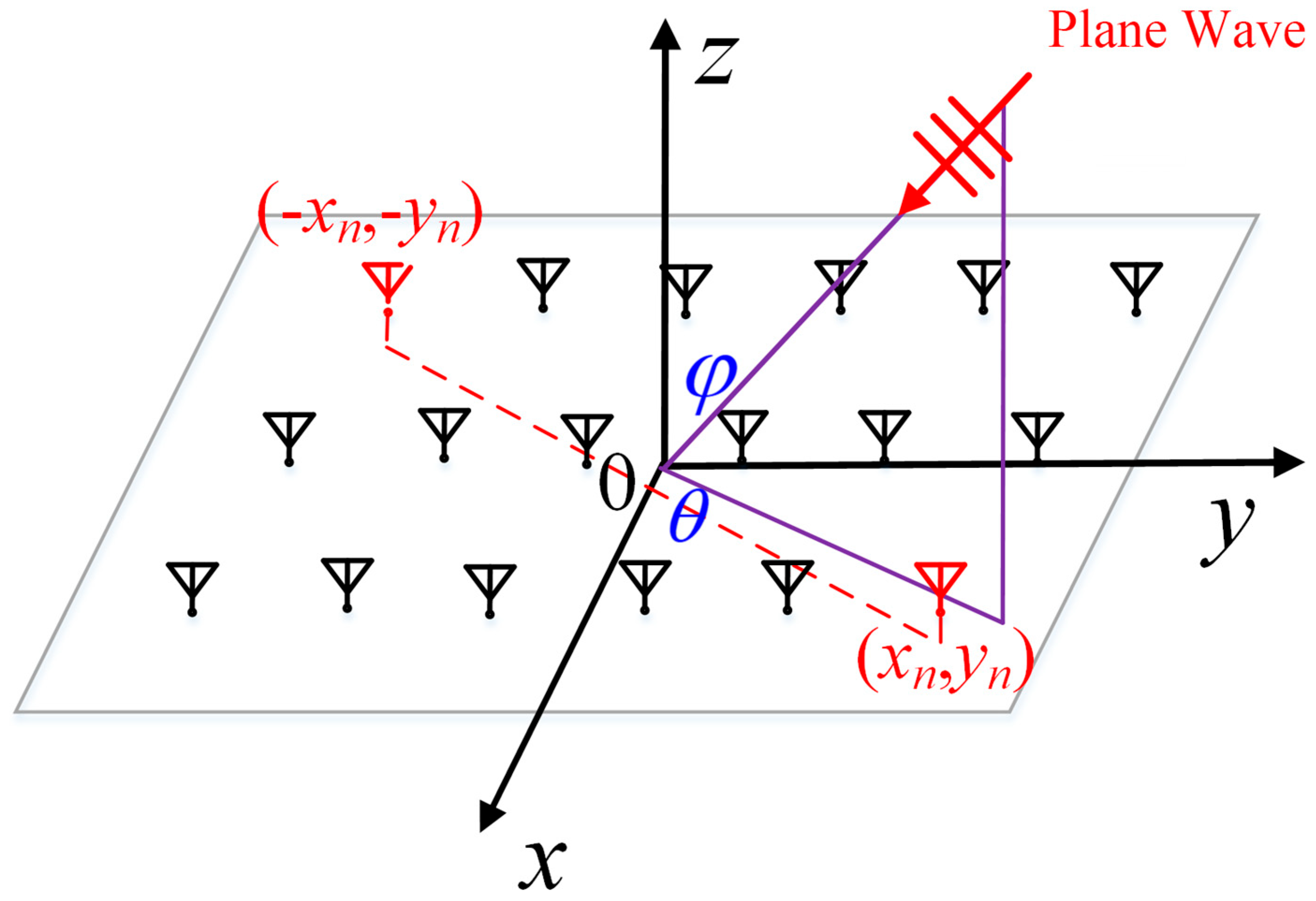
2. Van Atta Array Backtracking Principle

The Van Atta array is composed of multiple symmetrical antenna units. The two symmetrical antenna units are connected by transmission lines of isoelectric length. In this way, the EM waves received by each antenna are radiated by the symmetrical antenna after passing through the transmission line.
As shown in Figure 1, the antennas are uniformly arranged on the z = 0 plane for a two-dimensional planar Van Atta array. Two symmetrical antenna elements are connected by transmission lines of equal electrical length. Any antenna element located at the position (xn, yn) is connected to the antenna element located at (−xn, −yn) through the transmission line of equal electrical length. For incoming waves at any azimuth angles θ and elevation angles φ in space, the phases of the electromagnetic waves received by the two connected antenna units are φ n r x n , y n and φ n r x n , y n , respectively, which can be expressed as
φ n r x n , y n = k i n x n sin ϕ cos θ + y n sin ϕ sin θ φ n r x n , y n = k i n x n sin ϕ cos θ y n sin ϕ sin θ
where kin is the propagation constant of EM waves in space. Assuming that the length of the transmission line connecting two symmetrical antenna units is l, and its phase delay is φ l , then the initial phase of the received EM wave re-transmitted is
φ n t x n , y n = φ n r x n , y n φ l φ n t x n , y n = φ n r x n , y n φ l
Then the phase sum of the signals sent and received by each antenna unit is
φ n t x n , y n + φ n r x n , y n = φ n r x n , y n + φ n r x n , y n φ l φ l φ n t x n , y n + φ n r x n , y n = φ n r x n , y n + φ n r x n , y n φ l φ l
The phase sum of the signals sent and received by the array antenna unit is a certain value. It satisfies the generalized phase conjugation condition and can realize the direction backtracking function of the signal [42,43,44,45].

3. Van Atta Array Design

The design of Van Atta array in this article includes antenna design, transmission line network design, and SPST switch design.

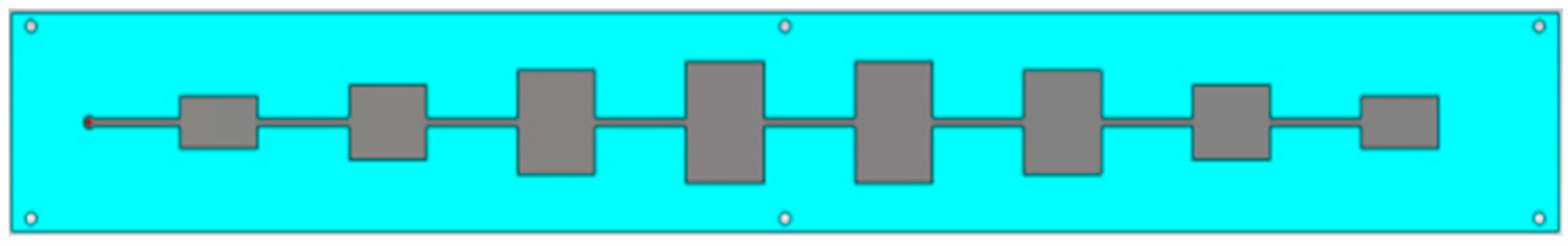
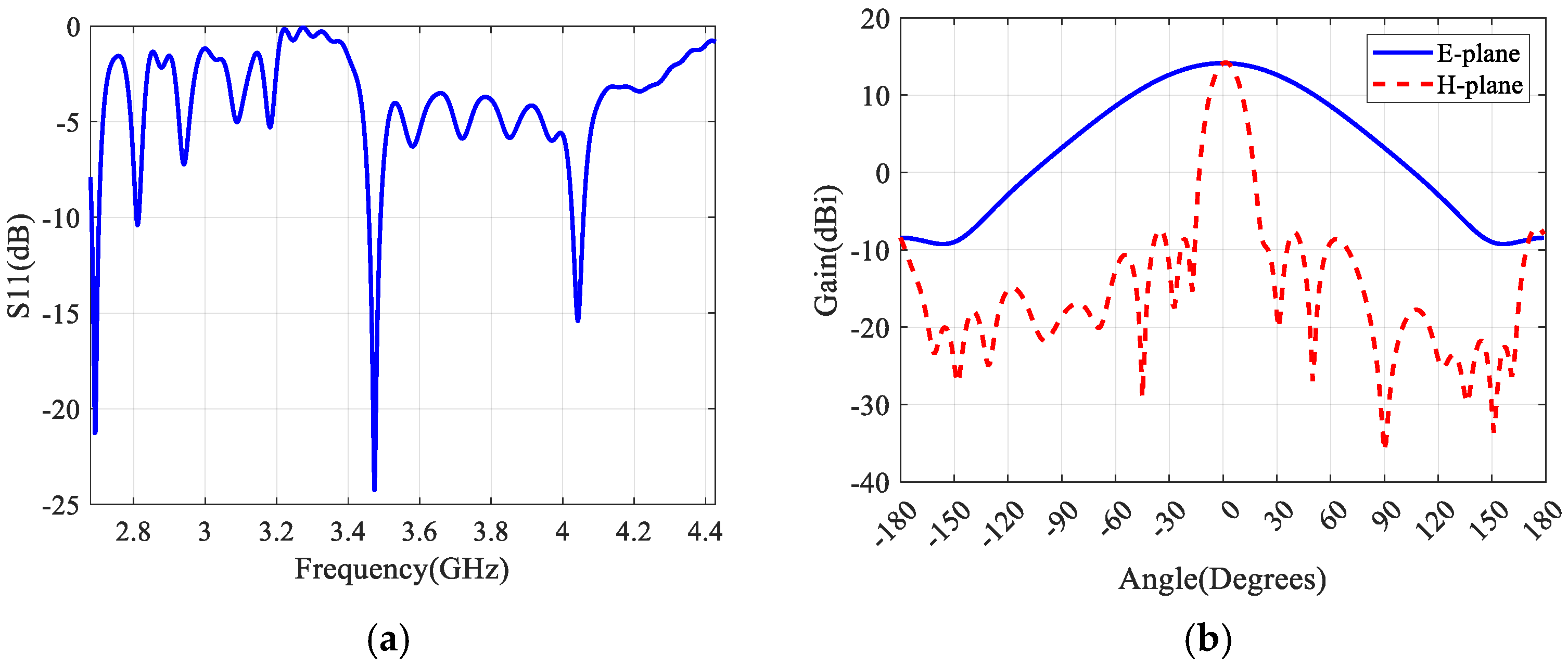
3.1. The Design of Antenna

As a Van Atta array antenna, the series-fed array antenna has unique advantages over other antenna array connections due to its light weight, compact size, and simple feeding. To maximize the overall array efficiency and achieve high gain, a series resonant rectangular microstrip patch array is used as the antenna for the Van Atta array, as shown in Figure 2.
The designed Van Atta array consists of eight columns of resonant series-fed rectangular microstrip patch arrays. Eight patch antennas are symmetrically distributed at equal intervals in each column. The interval between two adjacent patches is the wavelength λg to weaken the mutual coupling of adjacent elements. The width of the patch antenna element decreases sequentially from the center to both ends to reduce side lobes.
From the perspective of equivalent circuits, a series array is a combination of parallel resonant circuits, with each resonant circuit representing a single surface mount component. Due to the fact that adjacent patches are spaced apart by a resonant wavelength, their reactances cancel each other out, leaving a parallel combination of input resistors. Using CST 2022.4 simulation, the characteristics of the designed antenna are shown in Figure 3.
The reflection coefficient of the designed resonant series patch array is shown in Figure 4a, which is less than −10 dB in the frequency band of 3.45–3.55 GHz. The gain of the antenna is 14.2 dBi at 3.5 GHz. As shown in Figure 4b, on the E-plane of the antenna, the antenna gain should be maximized to maintain the required backward reflectivity. By adjusting the width of the rectangular patch, the sidelobes are reduced to 15 dB smaller than the main lobe. On the H-plane, in order to ensure a large RCS of the Van Atta array under oblique incidence, it is necessary to ensure relatively consistent gain over a large angle range on the H-plane, which is also a unique feature of the Van Atta array antenna.

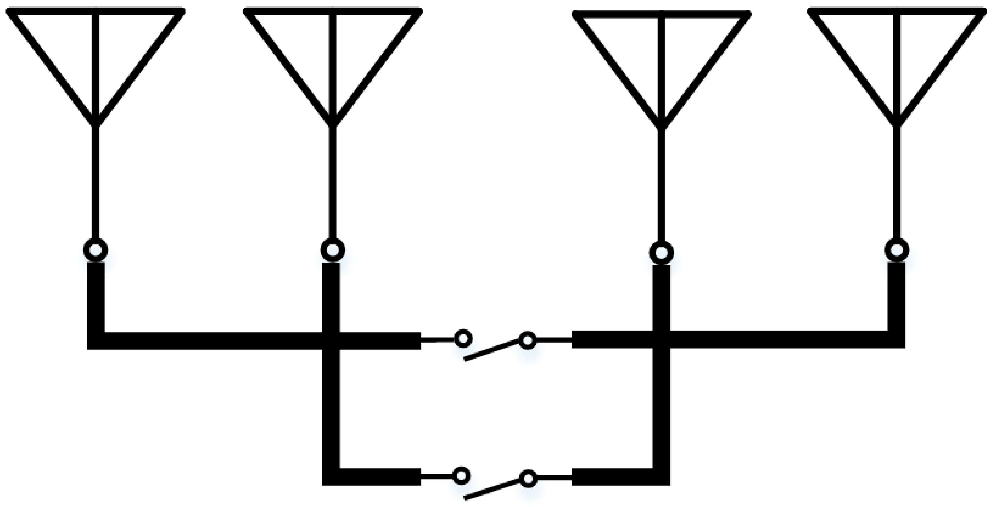
3.2. The Design of Transmission Line Network

As shown in Figure 3, four grounded coplanar waveguide (GCPW) is used as the Van Atta transmission line network to reduce radiation loss and crosstalk between adjacent transmission lines. The length of each transmission line differs by an integer number of wavelengths to weaken transmission line losses. The length of the four GCPW lines are 2.5 λg, 3.5 λg, 4.5 λg, and 5.5 λg, respectively. The phase delay of four transmission lines at 1–6 GHz is presented in Figure 5. The same phase delay is obtained for four GCPW lines at 3.5 GHz. The working bandwidth designed for the VanAtta array is 3.45–3.55 GHz. By calculating the phase delay difference between the transmission lines within the working bandwidth, which is within 5.15°, it can meet the backtracking requirements of Van Atta.
The GCPW line consists of the ground on the bottom layer of the PCB board and the coplanar waveguide (CPW) on the top layer of the PCB board. The CPW consists of the middle signal line and the ground on both sides. The two semi-infinite ground planes of the CPW are connected to the ground plane of the bottom layer of the PCB through vias.
By controlling the rotating table in the range of −60° to 60°, the monostatic RCS of the designed Van Atta array at different incidence angles are tested and compared with the flat metal plate of the same size, the RCS characteristics are obtained as shown in Figure 6.
The Van Atta array and the flat metal plate of the same size have the same RCS at normal incidence. As the incidence angle increases, the first side lobe of the RCS of the flat metal plate rapidly decreases by 13 dB. The RCS of the Van Atta array is attenuated slowly due to the directional retrospective characteristics at oblique incidence, its main lobe is wider, and the side lobe attenuation is about 4 dB. This is due to the attenuation of the retrospective signal on the transmission line and the direction of the antenna at oblique incidence. Compared with the flat metal plate, the RCS of the Van Atta array is more than 15 dB larger than that of the flat metal plate in a wider range of lateral incidence angles (greater than 10°).

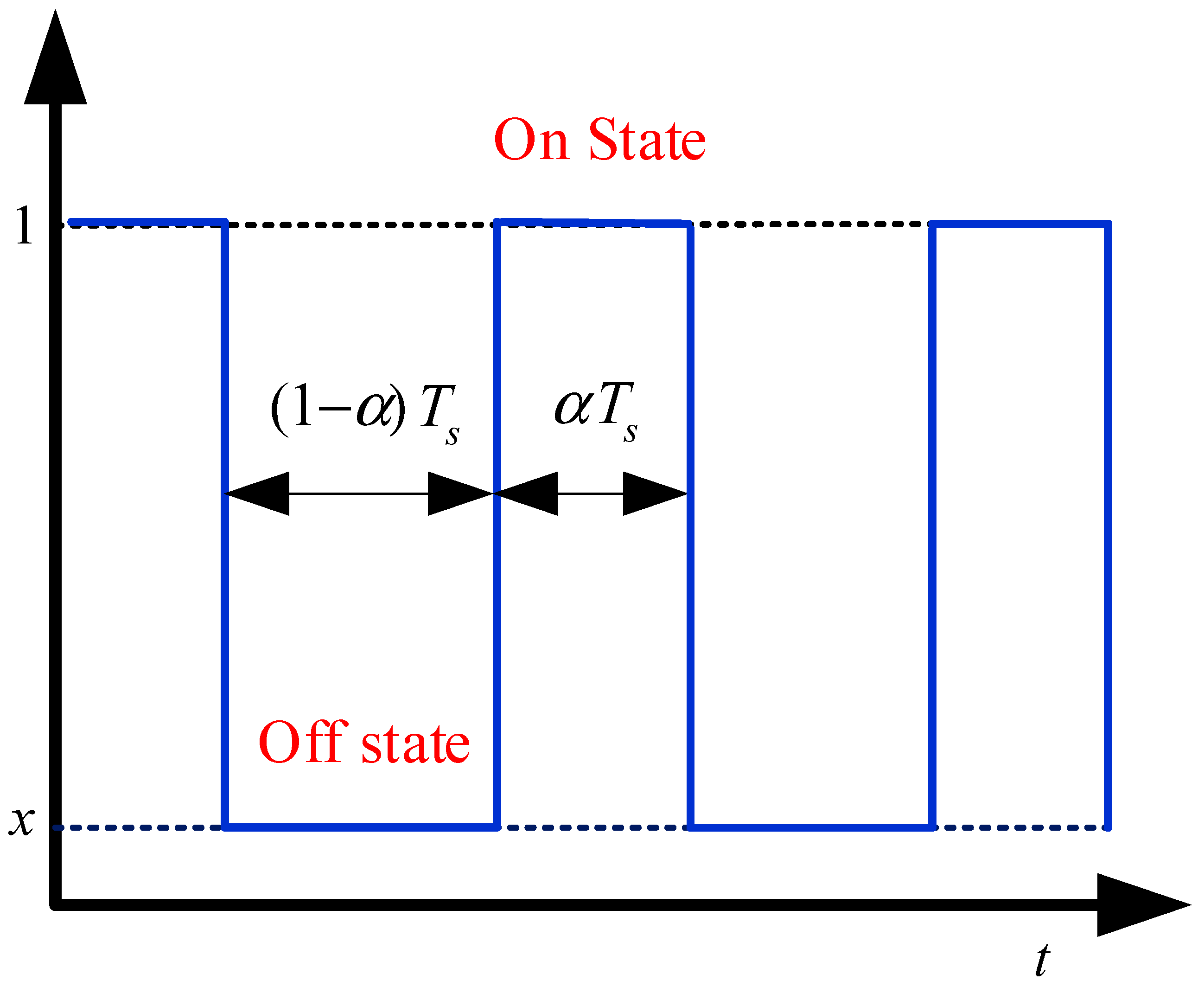
3.3. Establishment of the On–Off Model of the Van Atta Array

Based on the phase conjugation principle, the antenna array forms a Van Atta array and can achieve the direction of incoming waves. When not connected, since the mutually symmetrical antenna units cannot form a path, the phase conjugation principle cannot be satisfied, and a Van Atta array cannot be formed to realize the backscattering of the signal. As shown in Figure 7, the on–off control of the Van Atta array is realized by adding electronically controlled microwave switching elements to the transmission line of equal electrical length connecting two symmetrical antenna elements in the array. The design and analysis of the electronically controlled microwave switching elements are as follows.
The electronically controlled microwave switching element can realize the conduction and cut-off of the transmission line under the condition of external excitation voltage or excitation current. In this way, the Van Atta array can be electrically controlled to switch between the two states of whether the directional backscattering performance of incident signal can be realized. Since the RCS of the Van Atta array in the oblique incidence of plane waves is mainly composed of backscattering signals, it can be achieved by controlling the microwave switch.
Then the monostatic radiation field intensity of the Van Atta planar array is equivalent to the weighting of the two-dimensional directivity coefficient of the antenna, as shown in Figure 8. The monostatic radiation field intensity is the largest when the wavefront is parallel to the array plane. With the increase in the angle between the wavefront and the X-axis and the Y-axis, the radiation field gradually decreases due to the decrease in the directivity coefficient of the antenna. Similar to the radiation field of the linear array, the monostatic radiation field at different angles is equivalent to the maximum value of the bistatic radiation field observed under the condition of the incident field.
Figure 9 shows the monostatic radiation field of the Van Atta planar array in the cut-off state: The monostatic radiation field intensity is the largest when the wavefront is parallel to the array plane. As the angle between the wavefront and the X-axis and Y-axis increases, the radiation field decreases rapidly. Therefore, monostatic radiation field control in the oblique incidence direction can be realized by on–off setting of the designed Van Atta array.

3.4. The Design of the SPST Switch

The design of the series SPST switch is shown in Figure 10. The PIN diode D1 is connected in series on the microwave path through the DC blocking capacitors C2 and C3. The cathode of the PIN diode is connected to the ground through the isolation inductor, and the anode is connected to the bias voltage through the LC isolator. A current limiting resistor R1 is connected in series with the bias voltage terminal to protect the PIN diode. In this way, the on–off of the PIN diode can be realized by controlling the bias terminal voltage. To reduce the influence of parasitic parameters, the required capacitance and inductance are all packaged with 0402 SMD. Isolation inductors use high-Q wire-wound inductors.

4. Time-Modulated Van Atta Array Testing

4.1. The SPST Switch Test

The insertion loss of the designed SPST switch under different bias voltages and currents tested by a vector network analyzer is shown in Figure 11. The resistance of the PIN diode decreases with the increase in the bias voltage, and its insertion loss decreases accordingly. When the bias voltage is 1.2 V, the bias current is 82 mA, and the resistance value of the PIN diode is 1.3 Ω, the insertion loss is −1.5 dB, which is close to the on state. When the bias voltage is 0 V, the resistance of the PIN diode is about 400 Ω, and the insertion loss is −14 dB, which is close to the cut-off state. In the working frequency band of 3.45–3.55 GHz designed in this article, the SPST switch ratio can reach 10 dB, which can meet the time-modulation requirements of the Van Atta array.

4.2. On–Off Van Atta Array Test

The designed on–off Van Atta array is shown in Figure 12b. Four microstrip switches are connected to eight antennas through coaxial lines of equal length. The microstrip switches use the same design to ensure that the four switch paths have the same phase delay.
In a microwave anechoic chamber, the RCS of the designed on–off Van Atta array was tested as shown in Figure 12a. The Van Atta array was vertically fixed on the turntable, with the array plane facing the test horn antenna, and the polarization direction of the array was the same as that of the antenna. The pulse frequency modulation signal was transmitted through a horn antenna, and the equivalent RCS of the Van Atta array was obtained by the ratio of the echo signal to the transmitted signal power.
When the switch is turned on, the Van Atta array can maintain a larger RCS in a larger angle range, and when the switch is turned off, the RCS decreases rapidly with the increase in the incident angle. Active Van Atta arrays have lost their directional backtracking properties. Due to the specular reflection, the Van Atta array is equivalent to a flat metal plate, and the RCS decreases rapidly with the increase in the incident angle.
The test results, as shown in Figure 13, show that within the range of ±10 °, the RCS of the on–off state of the Van Atta array is similar. However, when the incident angle is greater than 10 °, the RCS of the on state of the Van Atta array increases by about 5 dB compared to the off state due to its directional backtracking characteristic. This means that in the case of oblique incidence, the Van Atta array has the potential for amplitude modulation and can support time modulation.

5. Spectrum-Conversion Method

Based on the previous analysis, the AFSS reflector is made to perform periodic modulation as a function of time, as shown in Figure 14. The duty cycle of the rectangular pulse train is α, the pulse width is αTs, and the switching period is Ts. In this case, the periodic time-domain modulated signal is
p ( t ) = 1 x rect t α T s + δ t n T s + x
Among them, rect(·) is a rectangular pulse signal: when |t/αTs| < 0.5, its value is 1, otherwise it is equal to 0. ⊗ represents the convolution operation, δ(·) is the impulse function, and n is a positive integer.
According to the corresponding relationship of the Fourier transform, rect(t/αTs) ↔ αTssinc(αTsf), where sinc(y) = sin(πy)/πy. Its expanded Fourier series is
p ( t ) = A 0 + , n 0 + A n cos 2 n π f s t ^
Among them, the amplitude coefficient A0 = (1 − x)α + x, An = (1/nπ)(1 − x)(sin(nπα)), fs = 1/Ts is the modulation frequency, and the signal spectrum is expressed as
P ( f ) = , n 0 + A n δ ( f n f s ) + A 0 δ ( f )
In Equation (6), P(f) contains the impulse frequency component, which is generated by the time-domain DC component of the modulation function. Therefore, the spectrum contains many discrete sidebands, and the sideband envelopes obey the sinc function distribution.
When the radar signal s(t) is incident on the time-modulated AFSS reflector and its spectrum falls within the adjustable region, the echo signal can be expressed as
r ( t ) = s ( t ) × p ( t )
According to the relationship of the Fourier transform pair, the Equations (6) and (7) are brought into the equation, and the spectrum of the echo signal is
R ( f ) = S ( f ) P ( f )   = , n 0 + A n S ( f n f s ) + A 0 S ( f )
where S(f) is the spectrum of the incident signal s(t). It can be seen from Equation (8) that many harmonic components ΣS(f − nfs) are generated near the center frequency. An is the amplitude coefficient of the harmonic components, so the distribution of the harmonic components of the radar signal can be controlled by controlling the AFSS modulation parameters.
From the perspective of parameter control, the output characteristics of the matched filter are mainly affected by the AFSS modulation parameters, including the modulation frequency fs, the duty cycle α, and the absorption coefficient x. Next, the influence of the modulation parameters on the corresponding characteristics is analyzed by simulation. Here, the spectral shift effect of the single-frequency incident signal and the matched filtering result of the LFM signal are analyzed. Assume that the carrier frequency of the single-frequency signal is 500 MHz, the center frequency of the LFM signal is 10 GHz, the pulse width is 10 μs, the bandwidth is 50 MHz, and the modulation frequency Kr = B/Tp = 5 × 10¹² Hz/s.

5.1. Modulation Frequency fs
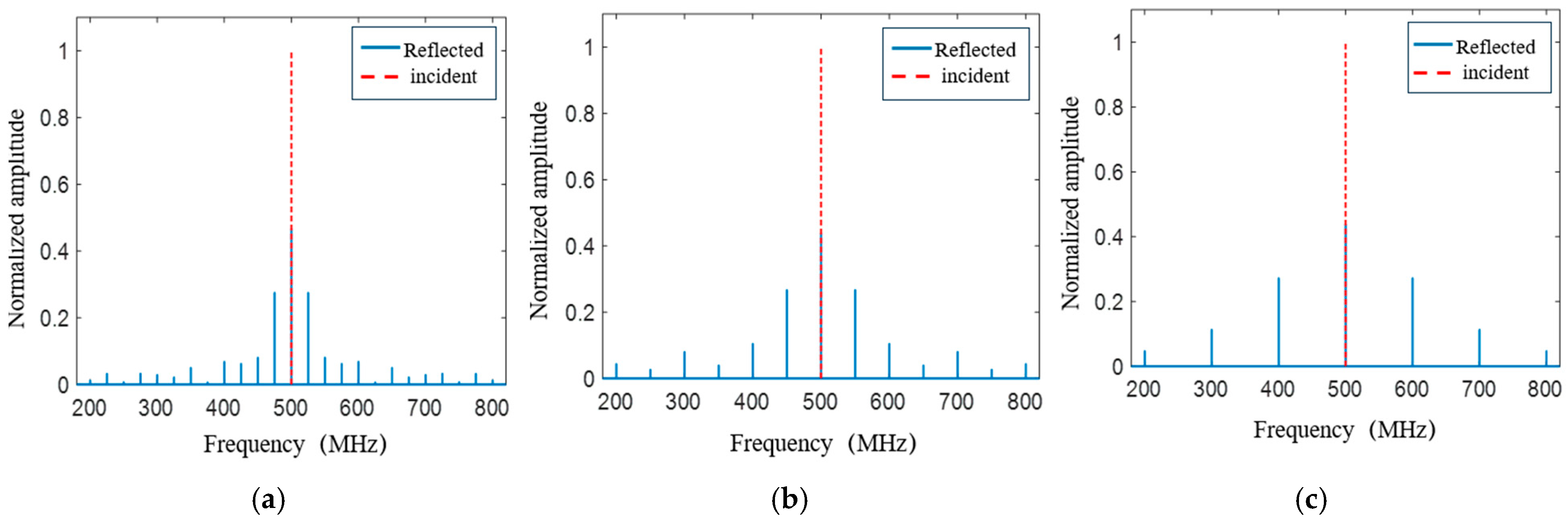
Assuming the duty cycle α = 0.4 and the amplitude coefficient x = 0.1, Figure 15 shows the simulation results under different modulation frequencies fs.
From the above figure, the modulation frequency fs increases, the interval between the modulated discrete harmonic spectra gradually increases. The peak value of the LFM signal matched filter output gradually disperses. Therefore, the modulation frequency mainly affects the position distribution of generated harmonics and output peaks, and its interval is positively correlated with it.

5.2. Duty Cycle α

Assuming that the modulation frequency of AFSS for single-frequency signal is 50 MHz, the modulation frequency for LFM signal is 5 MHz, and the amplitude coefficient x = 0.1, Figure 16 shows the simulation results under different duty cycles α.
As can be seen from the above figure, the discrete harmonic spacing is 50 MHz, while the matching filter peak spacing is 1μs, which has nothing to do with the duty cycle. The AFSS modulation duty cycle mainly affects the amplitude characteristics of the peak output. When α = 0.5, it can be seen from Figure 16b that the even-order peak output term disappears, which is consistent with Equation (8).

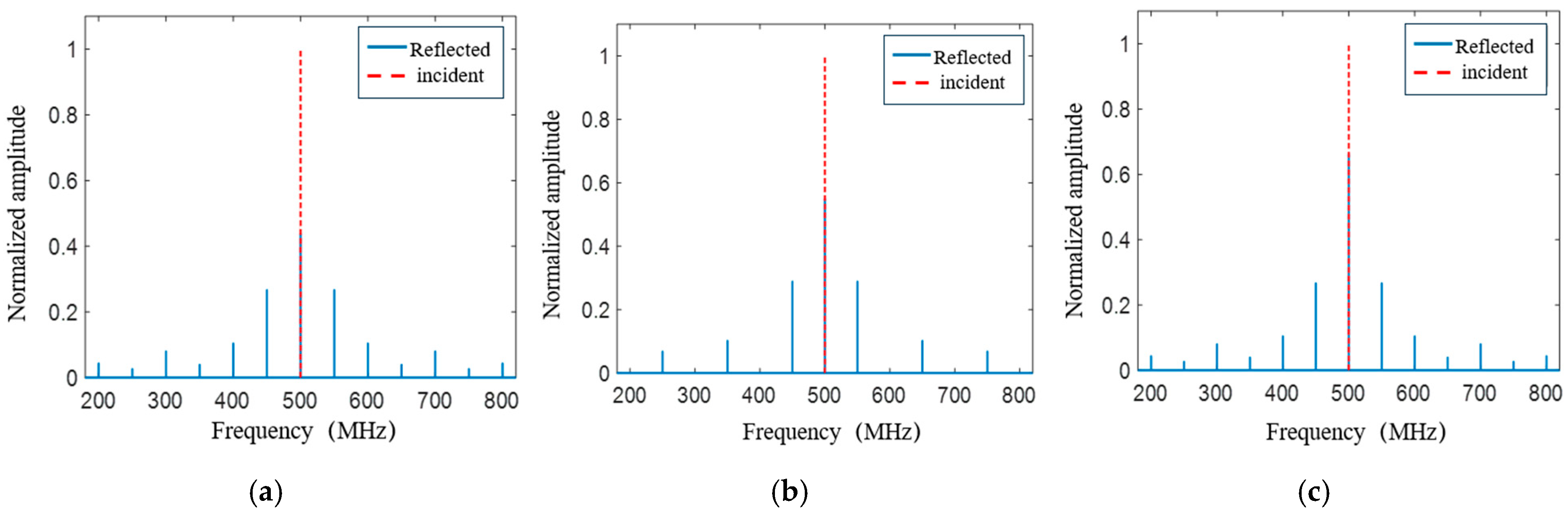
5.3. Amplitude Coefficient x

Assuming that the modulation frequency of AFSS for a single-frequency signal is 50 MHz, the modulation frequency for LFM signal is 5 MHz, and the duty cycle α = 0.4, Figure 17 shows the simulation results under different amplitude coefficients x.
Similarly, the amplitude coefficient x mainly affects the amplitude coefficient of the peak output. With the increase in x, the zero-order peak value continues to increase. On the contrary, the peak amplitude of other orders decreases. However, in general, the total energy of the signal increases as x increases, so the average level of the signal matched filter output is raised.
Among the three modulation parameters studied above, the modulation frequency and duty cycle put forward requirements for the switching speed of the SPST switch, and the amplitude coefficient x put forward requirements for the amplitude difference between the two states of the Van Atta array. To reach x = 0.1, the amplitude difference between the two states needs to reach more than 10 dB. With the 5 dB amplitude difference that the current Van Atta array can reach, x can reach 0.32. Therefore, in order to achieve better modulation effects, it is necessary to increase the switching speed of the SPST switch and the RCS contrast between the two states of the Van Atta array.

6. Conclusions

This paper proposes a retrospective method based on time-modulated Van Atta array. The Van Atta array includes eight antenna elements and four transmission lines connecting the antenna elements. The structure possesses the larger RCS at a wide angle due to its directional retrospective property. The SPST switches are added to the transmission line to control the on–off state of the structure. The switch-type active Van Atta array can switch between the on and off state by changing the bias voltage of the switches to obtain the RCS fluctuations. The measurement results show that the array in different states has 5 dB RCS difference. On this basis, the time-varying amplitude modulation model is established. Compared with the common time-varying modulation models implemented by artificial electromagnetic meta-materials, the method implemented by Van Atta array has greatly improved the modulation effect for oblique incidence and has a wider range of application scenarios. The symmetrical multiple harmonic components near the center frequency are generated in the modulated reflected signal. This phenomenon is expected to be applied in wide-angle wireless communication, electronic countermeasures, and other fields.

Author Contributions

Conceptualization, F.Z. and J.W. (Junjie Wang); methodology, K.S.; formal analysis, F.Z.; investigation, W.H.; resources, D.F.; data curation, J.W. (Junjie Wang); writing—original draft preparation, J.W. (Junjie Wang); writing—review and editing, J.W. (Jinrong Wang), W.H. and D.F. All authors have read and agreed to the published version of the manuscript.

Funding

This research was funded by the National Natural Science Foundation of China, grant number 62201589, and grant number 62371455.

Data Availability Statement

The datasets used and/or analyzed during the current study are available from the corresponding author on reasonable request.

Conflicts of Interest

The authors declare no conflicts of interest.

Abbreviations

The following abbreviations are used in this manuscript:
EMElectromagnetic
RCSRadar cross section
PSSPhase-switched surface
AFSSActive frequency selective surface
TMRATime-modulated reflector array
SPSTSingle-pole single-throw
GCPWGrounded coplanar waveguide
CPWCoplanar waveguide

References

  1. Ettorre, M.; Alomar, W.A.; Grbic, A. 2-D van atta array of wideband, wideangle slots for radiative wireless power transfer systems. IEEE Trans. Antennas Propag. 2018, 66, 4577–4585. [Google Scholar] [CrossRef]
  2. Henry, D.; Hester, J.G.D.; Aubert, H.; Pons, P.; Tentzeris, M.M. Long-range wireless interrogation of passive humidity sensors using van-atta cross-polarization effect and different beam scanning techniques. IEEE Trans. Microw. Theory Tech. 2017, 65, 5345–5354. [Google Scholar] [CrossRef]
  3. Chen, G.; Su, X.; He, L.; Guan, D.; Liu, Z. Coherent signal DOA estimation method based on space–time–coding metasurface. Remote Sens. 2025, 17, 218. [Google Scholar] [CrossRef]
  4. Li, H.; Li, Z.; Liu, K.; Xu, K.; Luo, C.; Lv, Y.; Deng, Y. A Broadband information metasurface-assisted target jamming system for synthetic aperture radar. Remote Sens. 2024, 16, 1499. [Google Scholar] [CrossRef]
  5. Liu, X.; Wu, Q.; Pan, X.; Wang, J.; Zhao, F. SAR image transform based on amplitude and frequency shifting joint modulation. IEEE Sens. J. 2025, 25, 7043–7052. [Google Scholar] [CrossRef]
  6. Yu, L.; Liu, J.; Liang, M.; Yu, X.; Xie, X.; Bi, H.; Hong, W. A structurally flexible occupancy network for 3-d target reconstruction using 2-d SAR images. Remote Sens. 2025, 17, 347. [Google Scholar] [CrossRef]
  7. Yang, Z.; Wang, Y.; Zhang, C.; Zhan, X.; Sun, G.; Liu, Y.; Mao, Y. Array three-dimensional SAR imaging via composite low-rank and sparse prior. Remote Sens. 2025, 17, 321. [Google Scholar] [CrossRef]
  8. Li, H.; Ma, C.; Zhou, T.; Wang, J.; Ye, D.; Sun, Y.; Zhu, W.; Denidni, T.A.; Ran, L. Reconfigurable Fresnel Lens Based on an Active Second-Order Bandpass Frequency-Selective Surface. IEEE Trans. Antennas Propag. 2020, 68, 4054–4059. [Google Scholar] [CrossRef]
  9. Zhu, L.; Wang, J.; Feng, D. An Approach for SAR feature reconfiguring based on periodic phase modulation with inter-pulse time bias. Remote Sens. 2025, 17, 991. [Google Scholar] [CrossRef]
  10. Wu, H.; Zhou, Q.; Sun, B.; Cao, Y.; Xu, Y. Asymmetric angular selected transmission in phase gradient metagratings and zero index metamaterials. J. Appl. Phys. 2023, 133, 223103. [Google Scholar] [CrossRef]
  11. Sui, R.; Wang, J.; Sun, G.; Xu, Z.; Feng, D. A dual-polarimetric high range resolution profile modulation method based on time-modulated APCM. IEEE Trans. Antennas Propag. 2025, 73, 1007–1017. [Google Scholar] [CrossRef]
  12. Chang, Y.; Wang, L.; Li, B.; Jiao, W. Phase switched screen for radar cloaking based on reconfigurable artificial magnetic conductor. IEEE Trans. Electromagn. Compat. 2021, 63, 1417–1422. [Google Scholar] [CrossRef]
  13. Chambers, B.; Tennant, A. The phase-switched screen. IEEE Antennas Propag. Mag. 2004, 46, 23–37. [Google Scholar] [CrossRef]
  14. Fang, X.; Li, M.; Ramaccia, D.; Toscano, A.; Bilotti, F.; Ding, D. Self-adaptive retro-reflective doppler cloak based on planar space-time modulated metasurfaces. Appl. Phys. Lett. 2023, 122, 021702. [Google Scholar] [CrossRef]
  15. Xu, L.; Feng, D.; Wang, X. Matched-filter properties of linear-frequency-modulation radar signal reflected from a phase-switched screen. IET Radar Sonar Navig. 2016, 10, 318–324. [Google Scholar] [CrossRef]
  16. Zhao, F.; Zhao, F.; Wang, J.; Wang, J.; Feng, D.; Feng, D.; Wu, Q.; Wu, Q.; Liu, X.; Liu, X. Time-modulated active frequency selective surface absorber/reflector for spectrum conversion. J. Appl. Phys. 2022, 131, 035101. [Google Scholar] [CrossRef]
  17. Zhang, H.; Hu, C.; Yang, J.; Tang, L.; Huang, D.; Shao, L.; Piao, M.; Li, C.; Shi, H. Graphene-based active frequency selective surface in microwave frequency. J. Appl. Phys. 2019, 125, 094501. [Google Scholar] [CrossRef]
  18. Rahmani-Shams, Y.; Mohammd-Ali-Nezhad, S.; Yeganeh, A.N.; Sedighy, S.H. Dual band, low profile and compact tunable frequency selective surface with wide tuning range. J. Appl. Phys. 2018, 123, 235301. [Google Scholar] [CrossRef]
  19. Xu, Y.; Feng, D.; Wang, J.; Sui, R. A method for transforming 2D imaging features with the AFSS-loaded rotating Luneberg lens reflector. IET Microw. Antennas Propag. 2022, 16, 860–868. [Google Scholar] [CrossRef]
  20. Valle, C.L.; Carranza, G.T.; Rumpf, R.C. conformal frequency selective surfaces for arbitrary curvature. IEEE Trans. Antennas Propag. 2023, 71, 612–620. [Google Scholar] [CrossRef]
  21. Saikia, M.; Srivastava, K.V.; Ramakrishna, S.A. A polarization-insensitive time-modulated frequency-selective surface for broad frequency range. IET Microw. Antennas Propag. 2022, 16, 37–45. [Google Scholar] [CrossRef]
  22. Saha, S.; Begam, N.; Chatterjee, A.; Biswas, S.; Sarkar, P.P. Reconfigurable frequency selective surface with tunable characteristics depending on intensity of atmospheric light. IET Microw. Antennas Propag. 2019, 13, 2336–2341. [Google Scholar] [CrossRef]
  23. Sun, G.; Wang, J.; Xing, S.; Huang, D.; Feng, D.; Wang, X. A flexible conformal multifunctional time-modulated metasurface for radar characteristics manipulation. IEEE Trans. Microw. Theory Tech. 2024, 72, 4294–4308. [Google Scholar] [CrossRef]
  24. Wang, J.; Feng, D.; Xu, Z.; Wu, Q.; Hu, W. Time-domain digital-coding active frequency selective surface absorber/reflector and its imaging characteristics. IEEE Trans. Antennas Propag. 2021, 69, 3322–3331. [Google Scholar] [CrossRef]
  25. Wang, J.; Feng, D.; Kong, Y.; Quan, S.; Xing, S. Imaging properties of nonperiodic time-varying active frequency selective surface. IEEE Trans. Antennas Propag. 2022, 70, 5884–5891. [Google Scholar] [CrossRef]
  26. Wang, Y.; Tennant, A. Experimental time-modulated reflector array. IEEE Trans. Antennas Propag. 2014, 62, 6533–6536. [Google Scholar] [CrossRef]
  27. Song, G.Y.; Cheng, Q.; Cui, T.J.; Jing, Y. Acoustic planar surface retroreflector. Phys. Rev. Mater. 2018, 2, 065201. [Google Scholar] [CrossRef]
  28. Feng, M.; Li, Y.; Zhang, J.; Han, Y.; Wang, J.; Ma, H.; Qu, S. Wide-angle flat metasurface corner reflector. Appl. Phys. Lett. 2018, 113, 143504. [Google Scholar] [CrossRef]
  29. Cui, T.J.; Liu, S.; Zhang, L. Information metamaterials and metasurfaces. J. Mater. Chem. C. 2017, 5, 3644–3668. [Google Scholar] [CrossRef]
  30. Zhang, L.; Chen, X.Q.; Liu, S.; Zhang, Q.; Zhao, J.; Dai, J.Y.; Bai, G.D.; Wan, X.; Cheng, Q.; Castaldi, G.; et al. Space-time-coding digital metasurfaces. Nat. Commun. 2018, 9, 1–11. [Google Scholar] [CrossRef]
  31. Zhao, J.; Yang, X.; Dai, J.Y.; Cheng, Q.; Li, X.; Qi, N.H.; Ke, J.C.; Bai, G.D.; Liu, S.; Jin, S.; et al. Programmable time-domain digital-coding metasurface for non-linear harmonic manipulation and new wireless communication systems. Natl. Sci. Rev. 2019, 6, 231–238. [Google Scholar] [CrossRef]
  32. Dai, J.Y.; Tang, W.; Yang, L.X.; Li, X.; Chen, M.Z.; Ke, J.C.; Cheng, Q.; Jin, S.; Cui, T.J. Realization of multi-modulation schemes for wireless communication by time-domain digital coding metasurface. IEEE Trans. Antennas Propag. 2020, 68, 1618–1627. [Google Scholar] [CrossRef]
  33. Li, X.-F.; Ban, Y.-L.; Sun, Q.; Che, Y.-X.; Hu, J.; Nie, Z. A compact dual-band van atta array based on the single-port single-band/dual-band antennas. IEEE Antennas Wirel. Propag. Lett. 2023, 22, 888–892. [Google Scholar] [CrossRef]
  34. Meng, Z.K.; Shi, Y. Antenna array design with self-adaptive in-band radar-cross-section reduction and beam scanning. IEEE Trans. Antennas Propag. 2023, 71, 1820–1831. [Google Scholar] [CrossRef]
  35. Wang, Y.; Piao, D.; Zuo, J. A wide-angle and fully polarimetric retrodirective array based on tri-polarized antennas with pattern complementation. IEEE Trans. Antennas Propag. 2022, 70, 4518–4525. [Google Scholar] [CrossRef]
  36. Huang, G.; Purushothama, J.M.; Ding, Y.; Li, X.; Gong, W. Synthesis-free backscatter directional modulation communication using Van-Atta arrays. IET Microw. Antennas Propag. 2022, 16, 654–659. [Google Scholar] [CrossRef]
  37. Trzebiatowski, K.; Rzymowski, M.; Kulas, L.; Nyka, K. Simple millimeter wave identification system based on 60 GHz van atta Arrays. Sensors 2022, 22, 9809. [Google Scholar] [CrossRef]
  38. Miao, Z.-W.; Hao, Z.-C.; Yuan, Q. A passive circularly polarized van atta reflector for vehicle radar applications. IEEE Antennas Wirel. Propag. Lett. 2017, 16, 2254–2257. [Google Scholar] [CrossRef]
  39. Song, K.; Feng, D.; Wang, J.; Xie, Q.; Liu, L. Phase modulation of retro-reflected radar echo signal using a microstrip van-atta array. IEEE Access 2019, 7, 96011–96018. [Google Scholar] [CrossRef]
  40. Ramaccia, D.; Tobia, A.; Toscano, A.; Bilotti, F. Antenna-based carpet device for extremely large obstacles: Experimental verification. In Proceedings of the 2018 IEEE International Symposium on Antennas and Propagation & USNC/URSI National Radio Science Meeting, Boston, MA, USA, 8–13 July 2018; pp. 2283–2284. [Google Scholar]
  41. Tobia, A.; Ramaccia, D.; Toscano, A.; Bilotti, F. Antenna-based carpet cloak: A possible frequency and angular broadband cloaking technique. In Proceedings of the 2016 10th International Congress on Advanced Electromagnetic Materials in Microwaves and Optics (METAMATERIALS), Marseille, France, 28 August–2 September 2017; pp. 358–360. [Google Scholar]
  42. Leong, K.; Miyamoto, R.; Itoh, T. Moving forward in retrodirective antenna arrays. IEEE Potentials 2003, 22, 16–21. [Google Scholar] [CrossRef]
  43. Miyamoto, R.; Itoh, T. Retrodirective arrays for wireless communications. IEEE Microw. Mag. 2002, 3, 71–79. [Google Scholar] [CrossRef]
  44. Jorgensen, D.; Loadman, C. Retrodirective Antenna Systems for Wireless Communications. CNSR. Available online: https://cnsr.cs.unb.ca/Download/PDF/a3b.pdf (accessed on 13 January 2024).
  45. Shiroma, W.; Miyamoto, R.; Shiroma, G.; Tuovinen, J.; Forsyth, W.; Murakami, B.; Tamamoto, M.; Ohta, A. Progress in retrodirective arrays for wireless communications. In Proceedings of the 2003 IEEE Topical Conference on Wireless Communication Technology, Honolulu, Hl, USA, 15–17 October 2003; pp. 80–81. [Google Scholar]
Figure 1. The phase conjugation principle of planar Van Atta array.
Remotesensing 17 01257 g001
Figure 2. The designed series-fed array antenna.
Remotesensing 17 01257 g002
Figure 3. The designed Van Atta array.
Remotesensing 17 01257 g003
Figure 4. The series-fed array antenna performance. (a) Antenna S11 coefficient; (b) Antenna E-plane and H-plane directional patterns.
Remotesensing 17 01257 g004
Figure 5. The phase delay simulation results.
Remotesensing 17 01257 g005
Figure 6. The RCS measurement results of the designed Van Atta array in a microwave anechoic chamber.
Remotesensing 17 01257 g006
Figure 7. On–off control Van Atta array principle.
Remotesensing 17 01257 g007
Figure 8. Monostatic radiation field intensity of Van Atta line array in on state plane.
Remotesensing 17 01257 g008
Figure 9. Monostatic radiation field intensity of Van Atta array in cut-off state plane.
Remotesensing 17 01257 g009
Figure 10. The periodic modulating signal in time domain.
Remotesensing 17 01257 g010
Figure 11. The measurement results of the SPST switch.
Remotesensing 17 01257 g011
Figure 12. On–off switching diagram of an active Van Atta array. (a) Testing environment; (b) Switch structure.
Remotesensing 17 01257 g012
Figure 13. The measurement results of the RCS of the switch-type active Van Atta array.
Remotesensing 17 01257 g013
Figure 14. The reflection coefficient of the switch-type active Van Atta array after periodic modulation.
Remotesensing 17 01257 g014
Figure 15. The spectral modulation results at different frequencies fs. (a) fs = 25 MHz; (b) fs = 50 MHz; (c) fs = 100 MHz.
Remotesensing 17 01257 g015
Figure 16. The spectral modulation results at different duty cycles α. (a) α = 0.4; (b) α = 0.5; (c) α = 0.6.
Remotesensing 17 01257 g016
Figure 17. The spectral modulation results at different amplitude coefficient x. (a) x = 0; (b) x = 0.1; (c) x = 0.33.
Remotesensing 17 01257 g017
Disclaimer/Publisher’s Note: The statements, opinions and data contained in all publications are solely those of the individual author(s) and contributor(s) and not of MDPI and/or the editor(s). MDPI and/or the editor(s) disclaim responsibility for any injury to people or property resulting from any ideas, methods, instructions or products referred to in the content.

