1. Introduction
Remote sensing cameras (RSCs) play a fundamental role in Earth observation by providing continuous, large-scale, and high-precision geospatial information for applications such as environmental monitoring, disaster assessment, climate studies, and natural resource management [
1,
2,
3,
4]. Accurate geometric positioning is a prerequisite for reliable image registration, target positioning, change detection, and the quantitative retrieval of geophysical parameters [
5]. More broadly, explicit geometric structures have also been exploited in multi-view and light-field imaging to establish reliable cross-view correspondences and support geometric inference. For example, epipolar geometry has recently been incorporated into light-field feature representation and cross-view correlation modeling for super-resolution and disparity estimation [
6], illustrating the broader value of geometry-aware modeling in image-based inference. However, although the geometric parameters of optical payloads are carefully calibrated before launch, their geometric characteristics inevitably change during long-term on-orbit operation due to launch vibration, structural stress release, thermal deformation, and the harsh space environment. These effects gradually degrade the geometric positioning performance of remote sensing imagery and are particularly significant for geostationary Earth orbit (GEO) wide-field area-array cameras, whose large field of view and long operational lifetime require sustained geometric stability. Therefore, reliable on-orbit geometric calibration is essential for maintaining the long-term geometric positioning performance of GEO optical remote sensing systems.
Ground control point (GCP)-based methods remain the most widely adopted approach for on-orbit geometric calibration of optical remote sensing cameras. Conventional methods estimate calibration parameters by establishing correspondences between image observations and accurately surveyed GCPs obtained from dedicated calibration sites or high-precision geospatial products [
7,
8,
9,
10,
11,
12,
13]. With the increasing availability of digital orthophoto maps (DOMs), digital elevation models (DEMs), coastline databases, and other geospatial datasets, automatic image matching techniques have further improved the efficiency of GCP extraction and enabled large-scale operational calibration [
14,
15,
16,
17]. These approaches have been successfully applied to numerous optical satellite missions and can achieve meter- or sub-meter-level positioning accuracy under favorable observation conditions. However, their performance remains highly dependent on the availability and quality of reliable GCPs. Cloud cover, seasonal surface variations, illumination differences, and weak image texture may significantly reduce feature matching reliability, limiting their applicability for frequent or global on-orbit calibration.
Stellar observation-based methods provide an alternative solution by exploiting stars as stable celestial references for on-orbit geometric calibration [
18]. Since stellar observations are independent of ground features and unaffected by cloud cover or surface changes, they can provide highly stable geometric references for estimating camera orientation parameters and compensating for thermal deformation or installation errors. These methods have been successfully applied to several optical payloads and geostationary imaging systems, demonstrating their effectiveness in maintaining geometric positioning performance [
19,
20,
21,
22]. However, their applicability depends on the availability, number, and spatial distribution of observable stars within the camera field of view. In addition, stellar calibration usually requires dedicated star observation modes or nighttime observations, making it difficult to perform continuously during routine Earth observation missions. These constraints limit the operational flexibility of stellar observation-based calibration, particularly for GEO wide-field imaging systems that primarily operate in Earth observation mode.
To reduce the dependence on dedicated calibration targets, several studies have investigated calibration strategies based on geometric consistency among multi-temporal or multi-attitude observations [
23,
24]. These methods estimate calibration parameters by exploiting the geometric relationships among homologous image features acquired under different viewing geometries, thereby reducing the reliance on explicitly surveyed control points. Although such approaches improve calibration autonomy, they generally require repeated observations, accurate attitude control, sufficient image overlap, or highly maneuverable satellite platforms. These requirements may be difficult to satisfy during the routine operation of GEO wide-field optical payloads, where continuous Earth observation is prioritized over dedicated calibration maneuvers.
For GEO wide-field imaging systems, Earth limb or horizon observations provide another source of naturally available geometric information. Horizon observations have long been exploited for spacecraft attitude determination by extracting the apparent contour of the Earth from camera images [
25,
26]. Modenini et al. [
25] demonstrated that observations of an ellipsoidal body can provide effective geometric constraints for attitude estimation, while Braun and Barf [
26] developed an image-processing-based horizon sensing approach for estimating the orientation of sounding rockets, launch vehicles, and spacecraft. Beyond attitude determination, horizon geometry has also been exploited for camera calibration. Deng et al. [
27] proposed a camera calibration method for a large-field-of-view infrared horizon sensor, demonstrating the relevance of accurate camera geometry to horizon-based sensing; however, the calibration relies on dedicated laboratory targets and a rotary-table-based procedure. Geometric calibration has also been investigated for specialized Earth limb imaging instruments [
28]. These studies demonstrate the potential of Earth limb or horizon observations as geometric references for attitude determination and camera calibration. However, the direct use of routinely acquired Earth limb observations for the on-orbit geometric calibration of GEO wide-field area-array cameras, particularly for estimating orientation-related calibration parameters through Earth limb geometric constraints, has received comparatively limited attention.
Motivated by the above considerations, this paper proposes an Earth-limb-constrained framework for on-orbit geometric calibration of GEO wide-field area-array cameras. The proposed framework formulates geometric calibration as a constraint-driven parameter estimation problem by jointly exploiting Earth limb observations and terrain elevation information. A unified geometric calibration model is established by introducing an equivalent camera-to-inertial attitude representation, which incorporates the combined effects of camera installation errors and attitude-related errors into a common parameterization. Rather than separately estimating multiple orientation-related parameter groups, the proposed unified parameterization reduces parameter coupling and represents their combined effects using three equivalent camera-to-inertial attitude parameters, thereby simplifying the calibration procedure and facilitating robust nonlinear optimization. Furthermore, an analytical reference Earth limb modeling method is developed based on the WGS-84 reference ellipsoid and ellipsoid-based affine transformation, enabling the corresponding reference Earth limb geometry to be determined analytically without iterative tangency computation. This formulation provides an explicit geometric basis for constructing the Earth limb constraints used in calibration parameter estimation. The proposed framework is validated through both simulation and real GEO on-orbit experiments. The experimental results demonstrate that the proposed framework can effectively improve the geometric positioning performance of GEO wide-field optical cameras while reducing the dependence on GCPs and dedicated stellar observations, thereby providing a practical solution for long-term on-orbit geometric calibration.
The remainder of this paper is organized as follows.
Section 2 presents the proposed Earth-limb-constrained calibration framework, including Earth limb extraction, the unified geometric calibration model, and the calibration parameter estimation method.
Section 3 describes the experimental datasets and validation results obtained from both simulation and real on-orbit observations.
Section 4 discusses the applicability, limitations, and future work of the proposed framework. Finally,
Section 5 concludes this paper.
2. Materials and Methods
2.1. Overview of the Proposed Framework
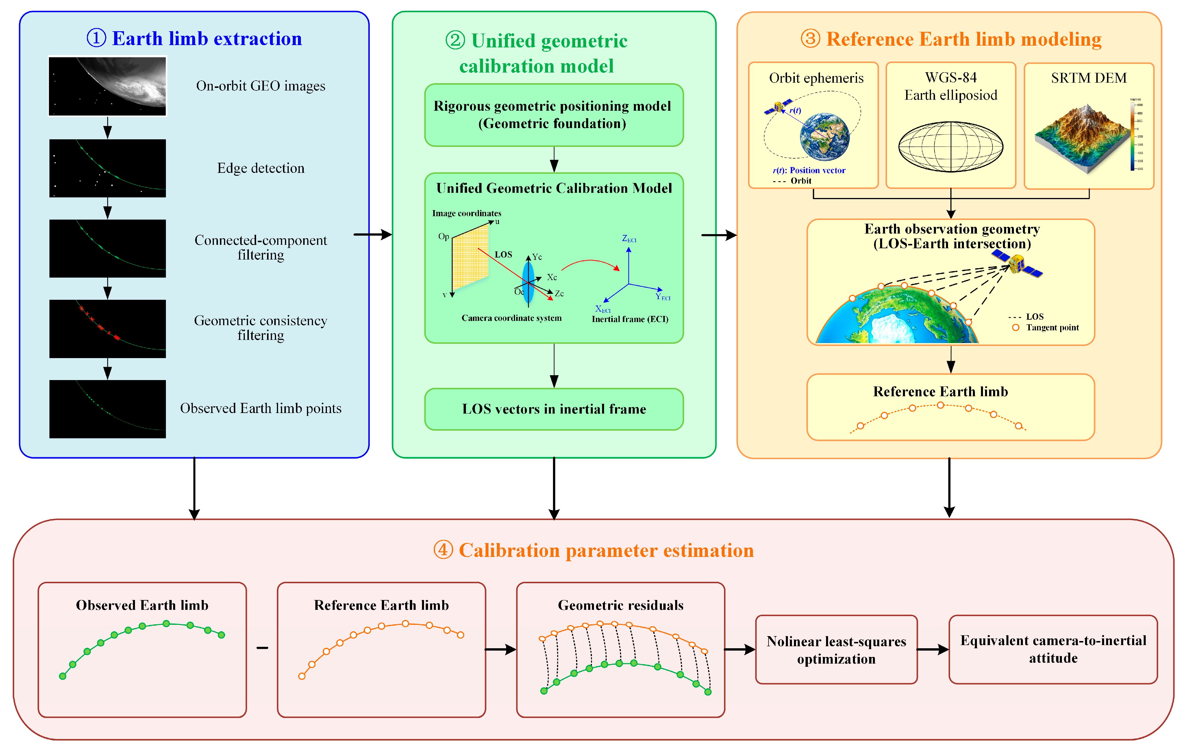
The overall workflow of the proposed Earth-limb-constrained geometric calibration framework is illustrated in
Figure 1. The framework consists of four major modules: Earth limb extraction, unified geometric calibration modeling, reference Earth limb modeling, and calibration parameter estimation.
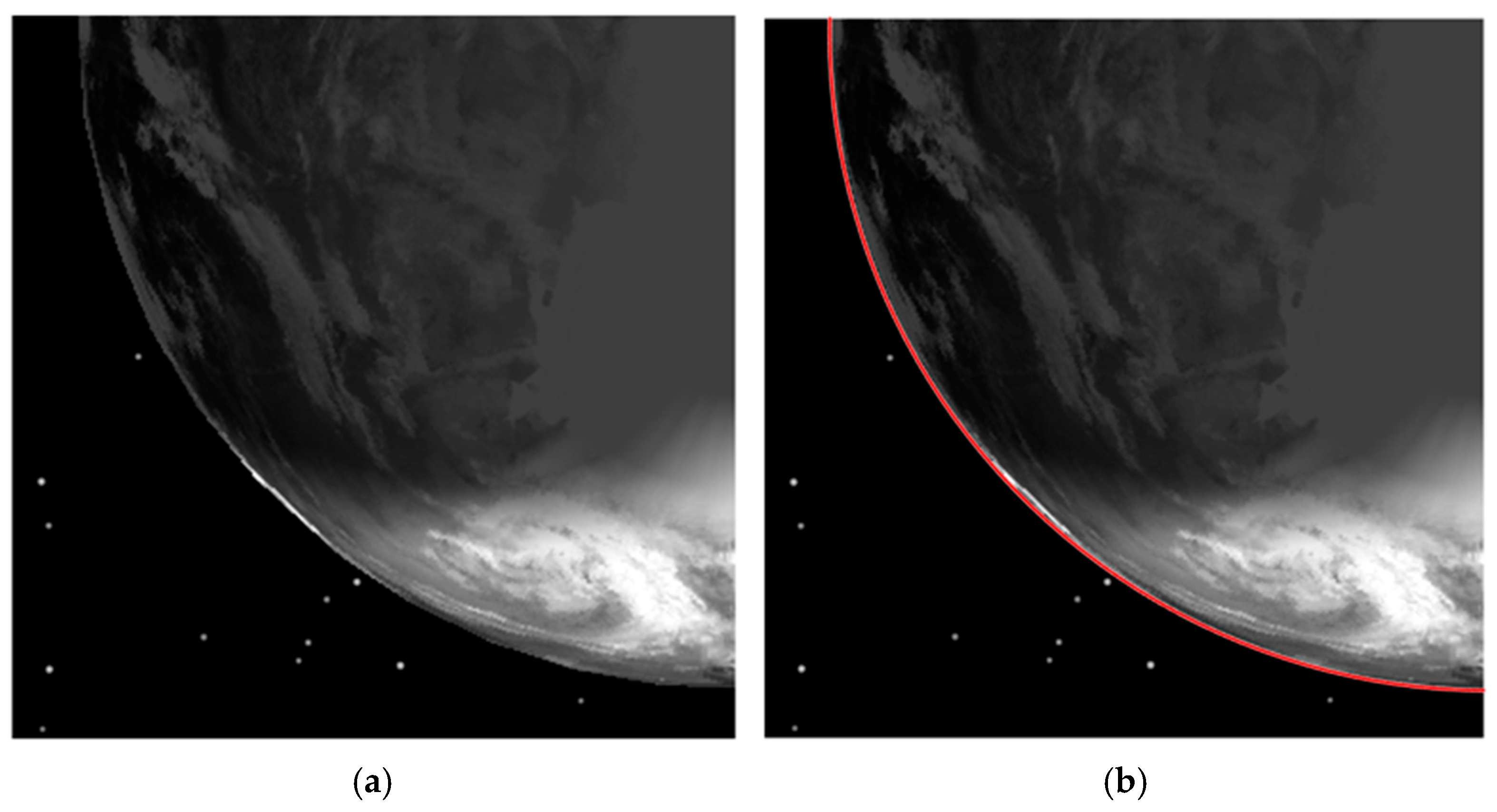
First, Earth limb points are extracted from GEO on-orbit images through a multi-stage procedure including edge detection, connected-component filtering, and geometric consistency filtering. The extracted limb points are subsequently converted into line-of-sight (LOS) vectors according to the camera imaging geometry. Subsequently, a unified geometric calibration model is established based on the rigorous geometric positioning model previously developed for GEO wide-field area-array cameras. An equivalent camera-to-inertial attitude representation is introduced to integrate the camera installation parameters and attitude-related parameters into a unified optimization framework, thereby reducing parameter coupling and simplifying the calibration process. Using the satellite orbit information together with the WGS-84 Earth ellipsoid model, the reference Earth limb corresponding to each observed LOS is then determined according to the Earth observation geometry. Terrain elevation derived from the Shuttle Radar Topography Mission (SRTM) DEM is further incorporated to refine the reference Earth limb positions and provide additional geometric constraints. Finally, the calibration parameters are estimated by minimizing the geometric residuals between the observed and reference Earth limbs through nonlinear optimization. The effectiveness of the proposed framework is subsequently evaluated using both simulation and real GEO on-orbit experiments.
2.2. Earth Limb Extraction
Accurate extraction of the Earth limb is a prerequisite for the proposed calibration framework because the extracted limb points constitute the geometric observations used for calibration parameter estimation. Owing to the strong radiometric contrast between the Earth disk and deep space in short-wave infrared imagery, the Earth limb can be reliably detected through edge analysis. Nevertheless, atmospheric scattering, cloud boundaries, stray light, and surface texture may introduce false edge responses that degrade calibration accuracy. Therefore, a three-stage Earth limb extraction procedure is adopted, consisting of edge detection, connected-component filtering, and geometric consistency filtering.
2.2.1. Edge Detection
The purpose of the first stage is to obtain candidate Earth limb points while preserving edge localization accuracy. A median filter is first applied to suppress image noise without significantly degrading edge structures. Subsequently, the Otsu [
29] adaptive threshold method is employed to separate the Earth disk from the background by maximizing the inter-class variance, thereby reducing the influence of atmospheric radiance variations. The Earth limb is then detected using the Canny edge detector [
30] because of its accurate edge localization and strong robustness against image noise.
Although the resulting edge map preserves the visible Earth limb arc, it also contains numerous non-Earth-limb structures, including isolated noise, cloud boundaries, and terrain edges, which require further filtering.
2.2.2. Connected-Component Filtering
The detected edge map is then processed using connected-component analysis to eliminate isolated edge fragments. Under typical observation conditions, Earth limb features generally form relatively large and continuous connected components. Therefore, connected-component size is used as a preliminary criterion to remove small false detections, while the present study focuses on images with clearly observable Earth limb features.
This preliminary filtering significantly reduces the number of candidate edge points while preserving the continuous Earth limb contour. However, atmospheric boundaries and large cloud edges may still satisfy the connectivity criterion and remain in the extracted edge set. Therefore, an additional geometric consistency constraint is introduced to further identify the true Earth limb.
2.2.3. Geometric Consistency Filtering
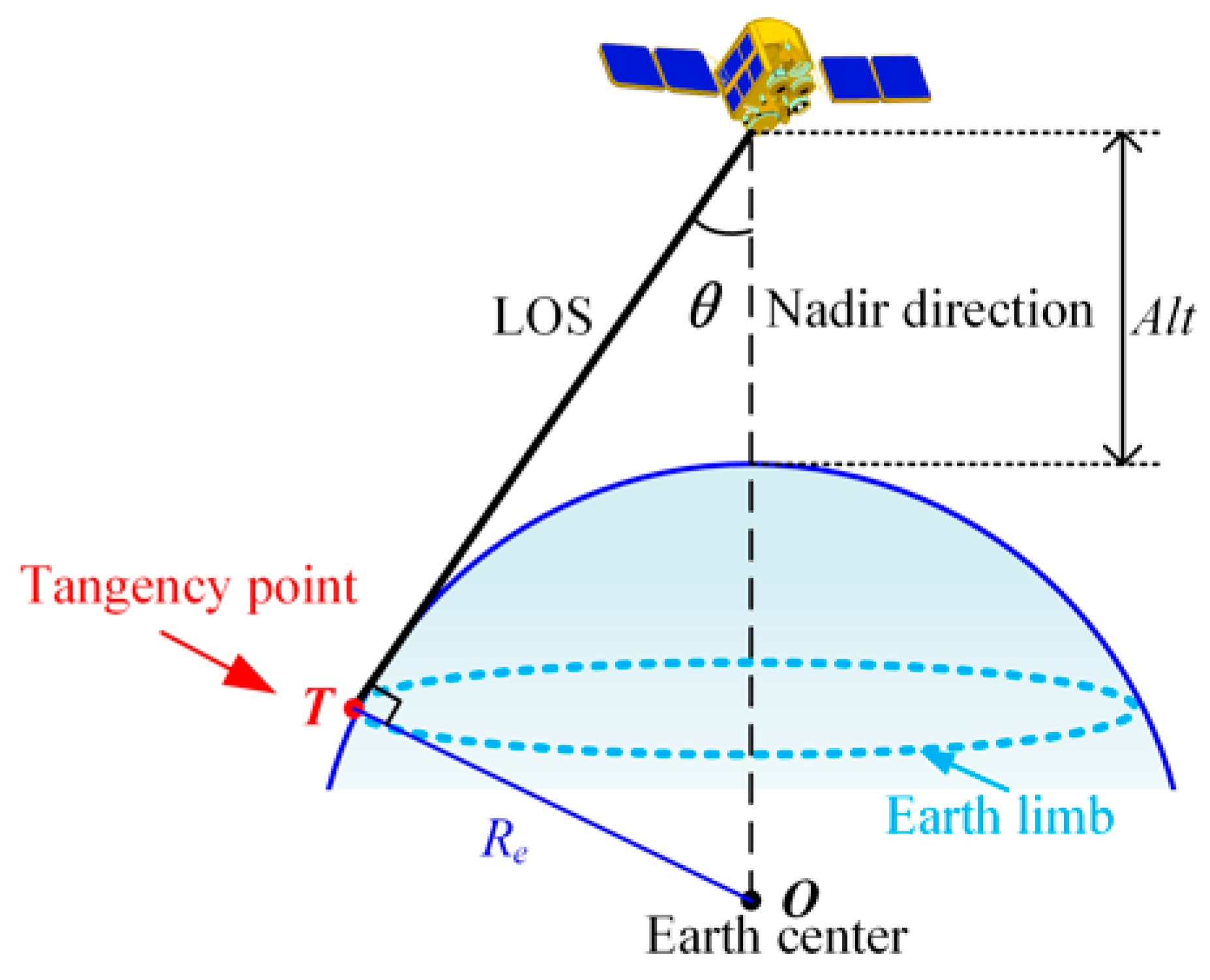
Unlike arbitrary image edges, the Earth limb follows a deterministic observation geometry governed by the relative positions of the satellite and the Earth. As illustrated in
Figure 2, an LOS corresponding to an Earth limb point is tangent to the Earth’s surface. Consequently, the viewing angle
θ between the LOS vector and the satellite nadir direction is uniquely determined by the Earth radius and the satellite altitude, which can be expressed as:
where
Re denotes the Earth radius and
Alt is the satellite altitude.
Based on this geometric constraint, candidate edge points inconsistent with the theoretical viewing angle are rejected, while the remaining edge points are retained as valid Earth limb observations. To ensure a uniform spatial distribution, redundant neighboring points are further removed using a grid-based non-maximum suppression strategy. The resulting Earth limb points provide reliable geometric observations for the unified calibration framework described in the following section.
2.3. Earth-Limb-Constrained Geometric Calibration Framework
The proposed calibration framework estimates the geometric calibration parameters by enforcing consistency between the observed Earth limb extracted from on-orbit imagery and the reference Earth limb predicted from the imaging geometry. Unlike conventional calibration methods that depend on GCPs or stellar observations, the proposed framework directly exploits the Earth limb as a globally observable geometric constraint. The framework consists of three components: a unified geometric calibration model, reference Earth limb modeling, and calibration parameter estimation.
2.3.1. Unified Geometric Calibration Model
The rigorous geometric positioning model provides the geometric foundation for Earth limb modeling and calibration parameter estimation, which establishes the mapping from image coordinates to the corresponding LOS vectors in the Earth-centered inertial (ECI) coordinate system. It consists of an internal orientation model that transforms image coordinates into LOS vectors in the camera coordinate system (CCS), and an external orientation model that projects the LOS vectors from CCS into the ECI frame. Accordingly, the imaging geometry can be expressed as:
where (
xcor,
ycor) is the distortion-corrected coordinates in the CCS, obtained by mapping the image point (
u,
v) onto the focal plane and correcting the distortion using the method described in [
31],
f is the focal length of the optical system,
Rcs is the camera installation matrix,
Rso is the transformation matrix from the satellite body coordinate system to the orbital coordinate system (OCS), and
RoECI is the transformation from the OCS to the ECI coordinate system.
Although the rigorous geometric positioning model accurately describes the imaging geometry, direct calibration of the external orientation parameters remains challenging during on-orbit operation. Camera installation deviations, attitude measurement errors, structural deformation, and other systematic effects jointly influence the LOS orientation and exhibit strong parameter coupling, making individual parameter estimation difficult and often unstable.
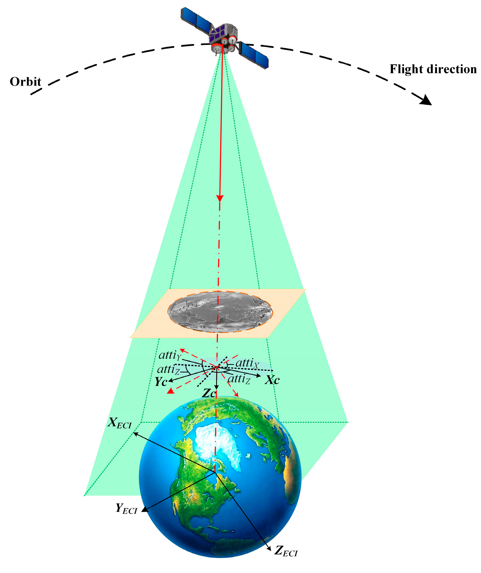
To alleviate this problem, an equivalent camera-to-inertial attitude representation is introduced to characterize the overall orientation of the camera with respect to the inertial frame. Instead of independently estimating the camera installation parameters and satellite attitude parameters, their combined influence is absorbed into three equivalent camera-to-inertial attitude angles, thereby establishing a unified geometric calibration model (UGCM) as shown in
Figure 3. This unified parameterization reduces parameter coupling and simplifies the subsequent calibration process while preserving the overall imaging geometry.
Accordingly, the LOS vector in the ECI coordinate system can be expressed as:
where
HcamECI denotes the transformation matrix from CCS to the ECI coordinate system and is parameterized by the equivalent camera-to-inertial attitude angles
attiX,
attiY,
attiZ, and
is the internal calibration model of the UGCM using the detector directional-angle model, which represents the viewing direction of each detector element by two directional angles and has been successfully applied to the on-orbit geometric calibration of wide-field area-array cameras [
32,
33]. The transformation matrix can be written as:
where
attiX,
attiY, and
attiZ represent the equivalent rotations about the
x-,
y-, and
z- axes of the camera coordinate system, respectively. These three parameters constitute the calibration parameters to be estimated in the proposed framework.
Since the reference Earth limb is defined with respect to the Earth-fixed reference surface, the LOS obtained in the ECI frame is subsequently transformed into the Earth-centered Earth-fixed (ECEF) coordinate system. For an observation acquired at time
t, the ECI-to-ECEF transformation is given by:
where
and
are the precession and nutation transformation matrices, respectively,
denotes the Earth rotation matrix, and
stands for the polar motion transformation matrix. The observation epoch
t is specified in Coordinated Universal Time (UTC), and the Earth orientation parameters required for the transformation are obtained from the Bulletin B published by the International Earth Rotation and Reference Systems Service (IERS) for the corresponding to the observation epoch. The resulting
is used in the subsequent reference Earth limb modeling based on the WGS-84 reference ellipsoid.
The equivalent camera-to-inertial attitude provides a compact representation of the combined external orientation errors and serves as the bridge between the observed Earth limb and its reference counterpart. The explicit ECI-to-ECEF transformation ensures that the LOS vectors and the Earth reference model are expressed in a consistent Earth-fixed coordinate system before reference Earth limb modeling and calibration parameter estimation.
2.3.2. Reference Earth Limb Modeling
Based on the unified geometric calibration model described above, the LOS vectors corresponding to the observed Earth limb points are first obtained in the ECI coordinate system and then transformed into the ECEF coordinate system at the corresponding observation epochs. The corresponding satellite position is obtained from the orbit data and expressed in the same ECEF coordinate system. A reference Earth limb geometry is then established based on the WGS-84 reference ellipsoid. Together with the satellite position and the current LOS, this reference geometry provides the basis for determining the geographic location and elevation associated with each LOS during the subsequent calibration process. In the present framework, the satellite position is treated as a known input, and the calibration therefore focuses on the attitude-related geometric errors represented by the equivalent camera-to-inertial attitude parameters.
The Earth is represented by the WGS-84 reference ellipsoid,
where
a = 6,378,137
m and
b = 6,356,752.314
m denote the semi-major and semi-minor axes of the reference ellipsoid, respectively. The WGS-84 ellipsoid is adopted because it provides a globally defined and widely used Earth-centered reference surface for satellite geolocation and is consistent with the geodetic coordinate framework used in the subsequent terrain-elevation constraint. The proposed affine-transformation formulation is not intrinsically limited to WGS-84; another reference ellipsoid can be adopted by replacing the corresponding ellipsoidal parameters. However, using a reference model inconsistent with the orbit/geodetic data would introduce systematic discrepancies into the reference Earth limb geometry and may propagate into the estimated calibration parameters.
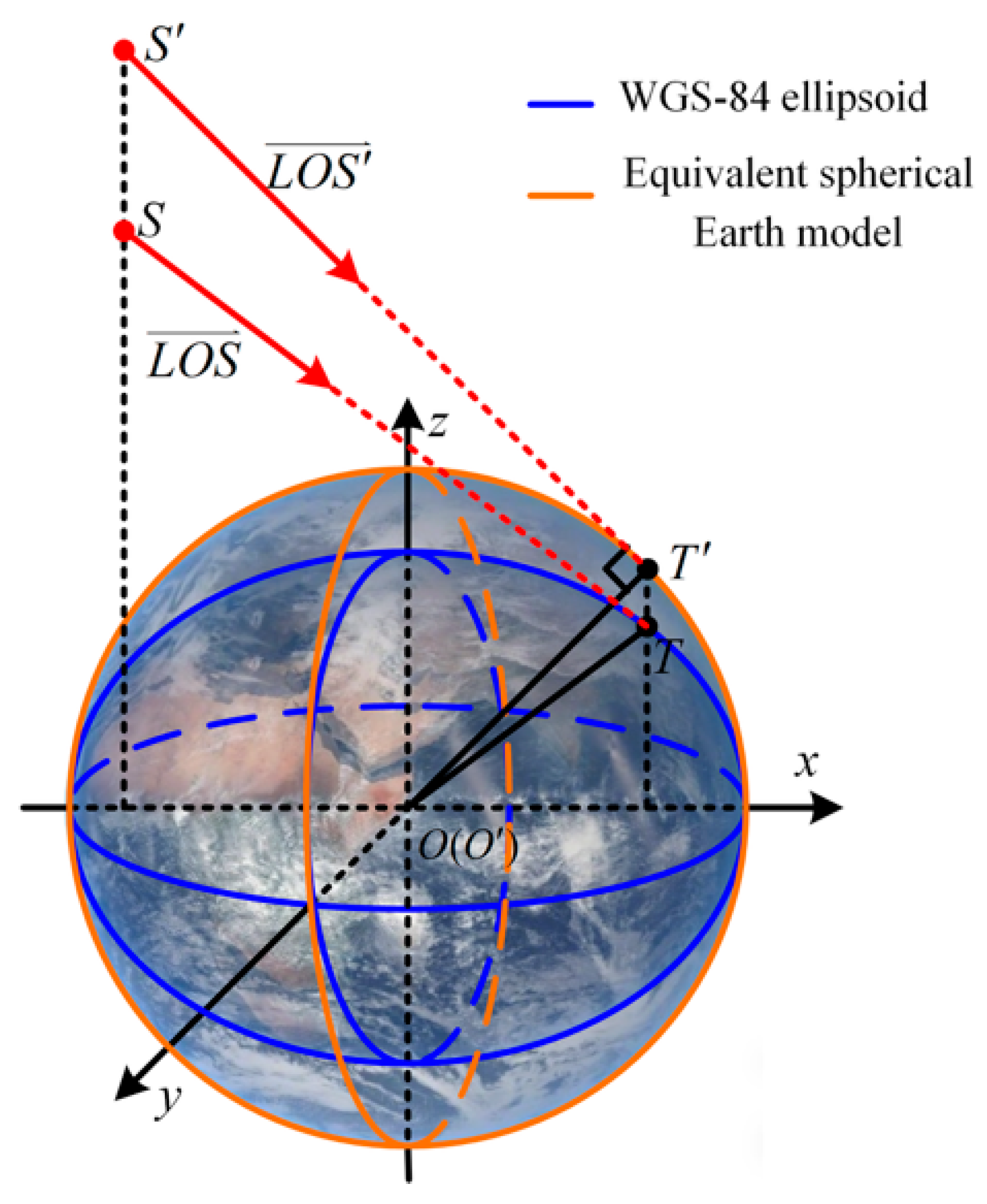
Direct determination of the tangency point on an ellipsoid generally requires iterative numerical optimization. To improve computational efficiency while preserving the geometric tangency relationship, an ellipsoid-based affine transformation is adopted, as illustrated in
Figure 4. In
Figure 4,
O and
O′ denote the centers of the WGS-84 ellipsoid and the transformed sphere, respectively;
S and
S′ represent the satellite positions before and after the affine transformation;
T and
T′ denote the corresponding Earth limb tangency points. The transformation scales the
z-axis such that the WGS-84 ellipsoid is mapped to a sphere with radius
a, while the satellite position and LOS are transformed consistently.
The affine transformation is defined by:
which transforms the Earth ellipsoid into a sphere with radius
a.
Under the transformed coordinate system, the satellite position vector, LOS vector, and Earth limb point are transformed simultaneously while preserving the tangency relationship. For an exact tangent LOS on the transformed reference sphere, the reference tangency point
T′ must satisfy two geometric conditions simultaneously. First, it must lie on the spherical surface,
In addition, the LOS from the satellite to
T′ is perpendicular to the radius vector
OT′ at the tangency point,
These two conditions jointly define the tangency point on the reference spherical surface. For a given LOS, the point satisfying the orthogonality condition can be analytically obtained by expressing the point on the LOS as
, where
t denotes the distance parameter along the LOS, and
is normalized to unit length. The corresponding value of
t is given by:
which gives the point of closest approach between the LOS and the Earth’s center. When the current LOS is exactly tangent to the reference sphere, this closest-approach point lies on the spherical surface and therefore satisfies
During the nonlinear calibration process, however, the trial LOS generated from the current calibration parameters may not be exactly tangent to the reference sphere. In this case, the point calculated from (11) is treated as a trial closest-approach point, rather than being assumed to be an exact tangency point.
After the affine transformation is inverted, the corresponding point in the original WGS-84 coordinate system is obtained. Its geographic coordinates and height are subsequently calculated for terrain-elevation constraint. Therefore, the WGS-84 model provides the reference Earth geometry, whereas the SRTM DEM introduced in the following subsection further constrains the elevation of the Earth limb point.
The proposed method avoids repeated numerical ray–ellipsoid intersection during the parameter optimization and provides an efficient analytical representation of the Earth limb geometry. More importantly, it separates the reference tangent geometry defined by the WGS-84 surface from the terrain-elevation constraint used for the actual calibration parameter estimation.
2.3.3. Calibration Parameter Estimation
The reference Earth limb geometry derived in the previous subsection is based on the WGS-84 reference ellipsoid and provides the global geometric reference for associating each current LOS with a geographic location and an ellipsoidal height. However, the physical Earth surface does not generally coincide with the zero-height WGS-84 reference ellipsoid because of terrain relief. To account for this difference, the proposed framework further incorporates terrain elevation information from the SRTM DEM as a local geometric constraint during parameter estimation. The calibration parameters are estimated by enforcing consistency between the ellipsoidal height calculated from the current imaging geometry and the terrain elevation at the corresponding geographic location. Unlike conventional calibration approaches that rely on discrete ground control points, the proposed framework exploits the Earth limb as a continuous geometric constraint.
For each Earth limb point, the closest-approach point associated with the current LOS is first transformed from the ECEF coordinate system to the geodetic coordinate system. The transformation is expressed as:
where
N denotes the radius of curvature in the prime vertical of the reference ellipsoid,
e is the first eccentricity of the WGS-84 ellipsoid, and (
) represent the latitude, longitude, and ellipsoidal height of the closest-approach point, respectively.
The corresponding terrain elevation is then interpolated from the SRTM DEM according to the calculated latitude and longitude. Let denote the terrain elevation associated with the i-th Earth limb point, and let denote the corresponding WGS-84 ellipsoidal height of the closest-approach point calculated from the current UGCM parameters. The elevation residual is defined as . Thus, the WGS-84 ellipsoid provides the reference coordinate system and ellipsoidal height, whereas the SRTM DEM supplies local terrain-elevation information that accounts for the deviation of the physical Earth surface from the zero-height reference ellipsoid.
The calibration parameters of the UGCM are then estimated by minimizing the elevation residuals of multiple Earth limb points using a nonlinear least-squares optimization implemented with the Levenberg–Marquardt (LM) algorithm:
where
K denotes the number of Earth limb points, and
represents the equivalent camera-to-inertial attitude parameters to be estimated. For the proposed terrain-constrained formulation, the objective jointly exploits the global Earth geometry represented by WGS-84 and the local terrain-elevation information provided by the SRTM DEM. The satellite position is treated as a known input obtained from the orbit data and is not included in the optimization parameter vector.
During each iteration, the current calibration parameters are used to generate the LOS vectors and the corresponding closest-approach points. Their geographic coordinates are then determined, and the associated SRTM terrain elevations are interpolated. The elevation residuals in (13) are subsequently used to update the calibration parameters. The process is repeated until the nonlinear least-squares objective converges.
It should be noted that the point evaluated during an intermediate iteration is not necessarily an exact tangency point on the WGS-84 reference surface. Rather, it is the closest-approach point associated with the current trial LOS. The role of the elevation constraint is to drive the calculated Earth limb height toward the physical terrain elevation corresponding to its geographic location, thereby accounting for local deviations of the Earth’s surface from the zero-height WGS-84 reference ellipsoid. Consequently, the final terrain-constrained Earth limb point is not required to satisfy the zero-elevation reference-surface condition when the local terrain has nonzero elevation.
The resulting equivalent camera-to-inertial attitude parameters are subsequently incorporated into the UGCM to generate calibrated LOS vectors for geometric positioning. By combining the Earth limb geometric relationship with the WGS-84 reference ellipsoid and globally available terrain-elevation information, the proposed framework provides an on-orbit geometric calibration constraint without requiring dedicated ground control points or additional calibration targets.
2.4. Accuracy Evaluation
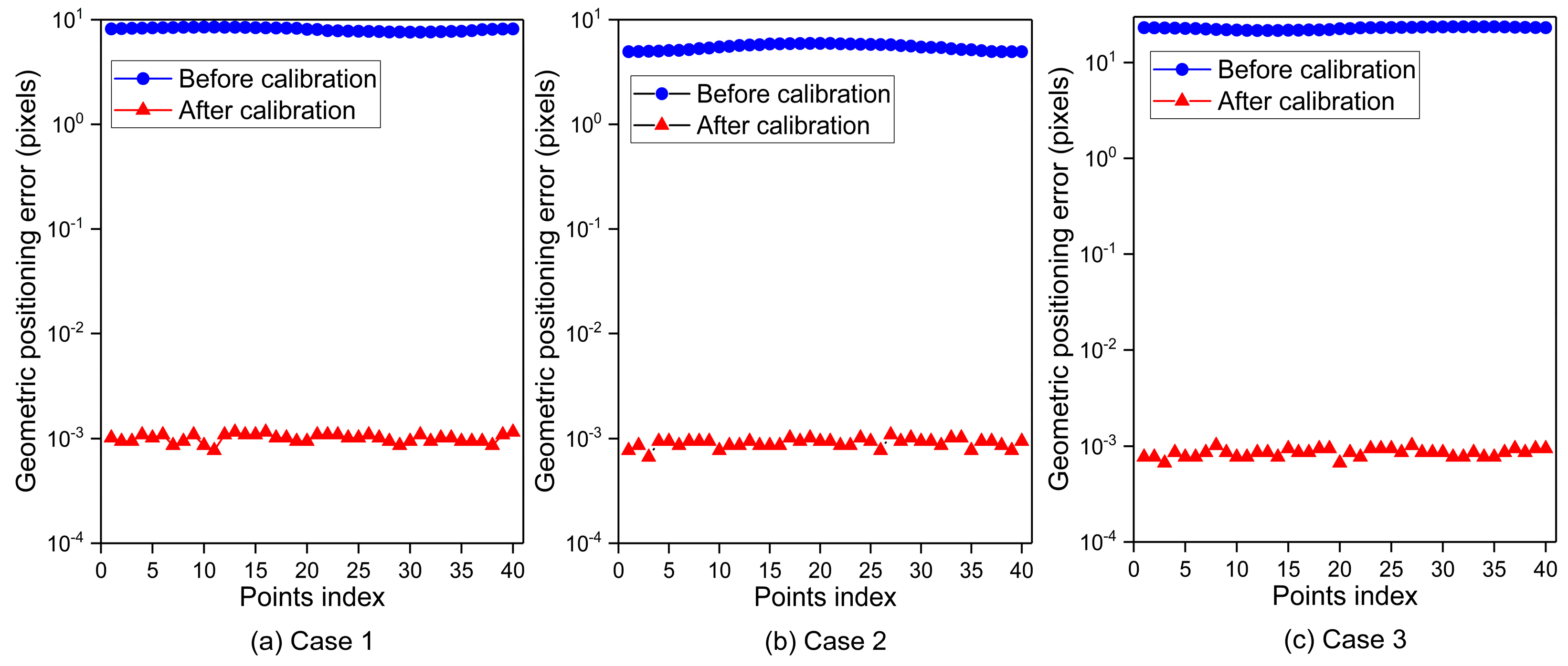
After calibration, independent validation is performed using different reference data for the simulation and on-orbit experiments. In the simulation experiments, the reserved synthetic Earth limb points are used for validation because their reference geometry is exactly known from the simulation. For the on-orbit experiment, stellar observations are employed as independent validation references owing to their precisely known inertial coordinates provided by astronomical catalogs. The stars are used only for accuracy assessment and are not involved in the Earth-limb-based calibration procedure.
For each validation star, the theoretical LOS vector in the J2000.0 ECI coordinate system is computed from its right ascension (
α) and declination (
δ) provided by the star catalog:
where
denotes the theoretical LOS vector corresponding to the validation star.
The calibrated LOS vector
is obtained from the proposed UGCM. The angular difference between the theoretical and calibrated LOS vectors is calculated as:
where
represents the pointing error in the inertial coordinate system.
To facilitate quantitative evaluation in image space, the angular error is converted into pixel units according to the instantaneous field of view (IFOV) of the camera:
where
Error denotes the equivalent geometric positioning error expressed in pixels. The nominal IFOV is 20 μrad/pixel. Because the full-frame angular extent is approximately 1.173° × 1.173°, the variation in local angular sampling across the focal plane is negligible for the present camera configuration. Therefore, the nominal IFOV is used as a small-angle approximation for converting angular error into pixel units.
The above evaluation is adopted throughout both the simulation and the on-orbit experiments presented in
Section 3. Since the validation relies solely on stellar observations and is independent of the Earth-limb-constrained calibration process, the resulting positioning accuracy provides an objective assessment of the effectiveness of the proposed framework.
4. Discussion
4.1. Interpretation of Experimental Results
The simulation and on-orbit experiments consistently demonstrated the effectiveness of the proposed Earth-limb-constrained calibration framework. Under ideal simulation conditions, the estimated equivalent camera-to-inertial attitude closely matched the predefined values, resulting in sub-pixel geometric positioning accuracy. These results verify the correctness of the proposed unified geometric calibration model and confirm the validity of the reference Earth limb modeling and parameter estimation strategy.
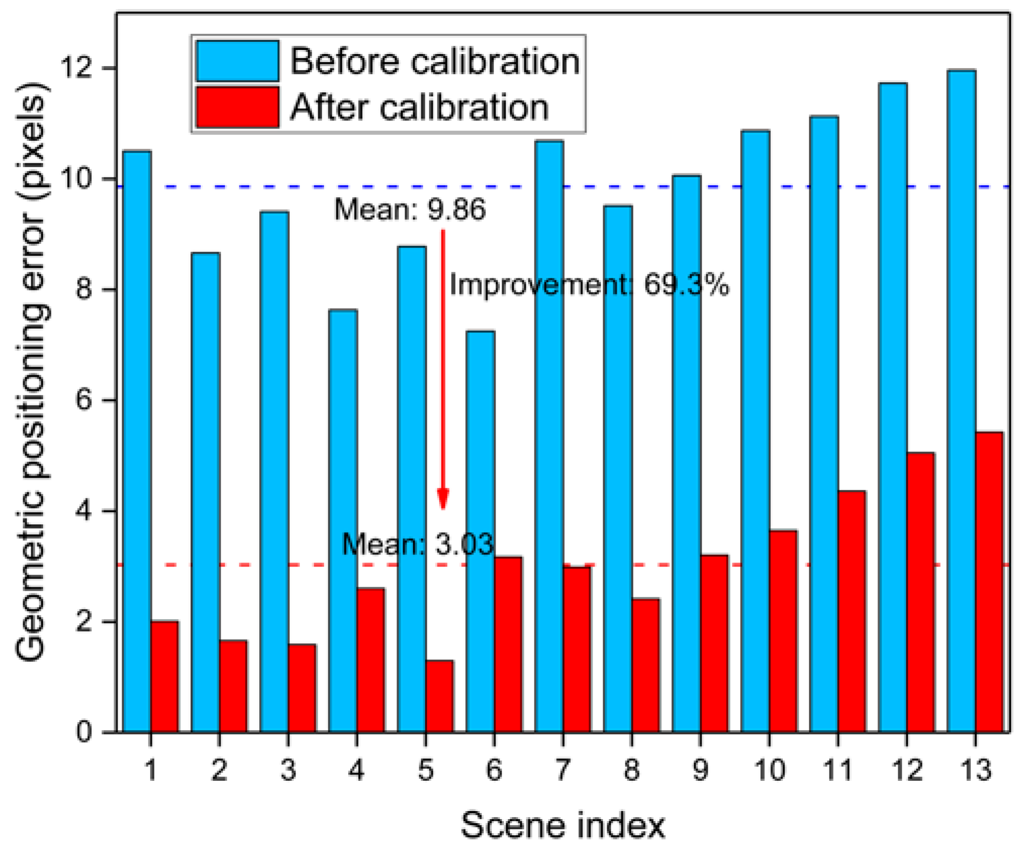
Compared with the simulation results, although the residual positioning error in the on-orbit experiments remained approximately 3 pixels after calibration, the positioning accuracy was consistently improved for all thirteen image scenes. This indicates that the proposed framework effectively compensates for the dominant external orientation errors accumulated during long-term on-orbit operation.
The achieved on-orbit positioning accuracy should also be interpreted in the context of existing calibration strategies. Conventional GCP-based methods can provide high geometric accuracy when sufficient well-distributed control information is available, whereas stellar-observation-based methods provide independent references under suitable observation conditions. The proposed framework is not intended to directly replace these approaches. Instead, it uses the Earth limb, a naturally observable large-scale geometric feature in routine GEO Earth imaging, as a complementary calibration constraint. The approximately 69% improvement in geometric positioning accuracy obtained from the thirteen on-orbit image scenes demonstrates that Earth limb observations can effectively compensate for the dominant orientation-related deviations in the investigated system. Because the reported accuracy of existing calibration methods depends strongly on factors such as sensor configuration, orbit, field of view, available reference information, initial geometric errors, and evaluation criteria, a direct numerical comparison of pixel-level accuracy across different studies would not be meaningful. Nevertheless, compared with approaches requiring dedicated GCPs or stellar observations, the main advantage of the proposed framework lies in its ability to perform geometric calibration using routinely acquired Earth images without dedicated calibration targets or additional observation planning.
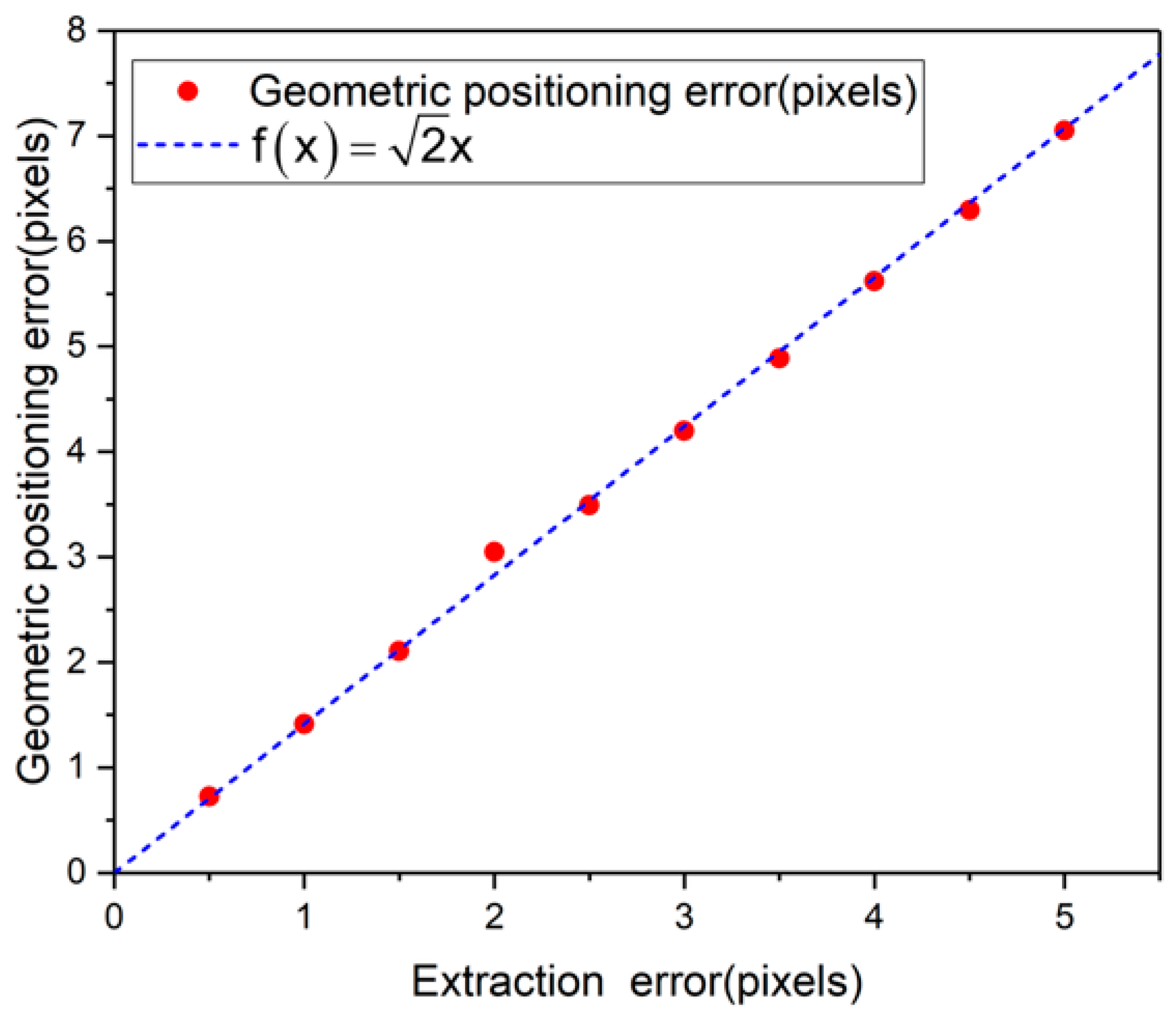
The difference between the simulation and on-orbit results is mainly attributed to practical imaging factors that are not considered in the simulation, including Earth limb extraction uncertainty, atmospheric transition effects near the limb, image noise, and residual errors in the internal geometric model. To further investigate the influence of Earth limb extraction accuracy, sensitivity simulations were conducted by introducing random perturbations into the image coordinates of the extracted Earth limb points. The extraction error represents the prescribed perturbation range in pixels; for example, an error level of 1 pixel indicates that the random perturbation is generated within [−1, 1] pixels. Perturbations were introduced separately into the horizontal coordinate, the vertical coordinate, and both coordinates. Fifty independent experiments were performed for each perturbation level. The corresponding results are shown in
Figure 8.
As illustrated in
Figure 8, the positioning error increases monotonically with increasing Earth limb extraction error. Simultaneous perturbations in both image coordinates produce larger positioning errors than perturbations introduced in either direction alone. For the same perturbation range, the combined effect of two-coordinate perturbations is approximately
times that of a single-coordinate perturbation, consistent with the combination of two independent orthogonal error components. These results demonstrate the significant influence of Earth limb extraction accuracy on the final calibration performance. The proposed optimization framework maintains stable convergence under the tested perturbation levels.
4.2. Implications, Limitations, and Future Work
Compared with conventional on-orbit calibration methods based on GCPs or stellar observations, the proposed framework differs fundamentally from these approaches by utilizing Earth limb observations acquired during routine Earth imaging as geometric constraints for calibration. For GEO wide-field area-array cameras, Earth limb observations are naturally available during normal mission operation and therefore provide a globally observable calibration feature without requiring dedicated calibration targets or additional observation planning. Rather than replacing existing calibration approaches, the proposed framework provides a complementary calibration strategy that can be integrated with conventional methods to support the long-term geometric maintenance of GEO optical payloads.
Another important characteristic of the proposed framework is the adoption of the unified geometric calibration model, in which the combined effects of camera installation deviations and satellite attitude errors are represented by an equivalent camera-to-inertial attitude. This unified parameterization reduces parameter coupling during optimization and simplifies the calibration process while preserving the physical imaging geometry. Combined with the analytical reference Earth limb modeling based on ellipsoid affine transformation, the proposed framework provides an efficient solution for large-scale on-orbit geometric calibration.
Although the proposed framework demonstrates promising performance, several limitations remain. The calibration accuracy is primarily constrained by the quality of Earth limb extraction. Atmospheric refraction, radiative transition effects near the limb, and cloud contamination may shift or blur the apparent Earth limb position, causing the extracted limb points to deviate from the geometric limb represented by the current reference model. Such deviations propagate through the elevation residuals and may consequently affect the estimated calibration parameters. These atmospheric effects are not explicitly modeled in the current framework; therefore, relatively clear Earth limb observations are preferred in the present implementation to reduce their influence. In addition, the satellite position is treated as a known input in the present framework. In practice, satellite position uncertainty may perturb the satellite-to-Earth viewing geometry and consequently affect the reference Earth limb geometry and the elevation residuals used for parameter estimation. The magnitude of this effect depends on the orbit determination accuracy and the observation geometry. Although orbit errors were not explicitly estimated in the present study, their influence should be considered when higher geometric calibration accuracy is required. Furthermore, the current framework estimates only the equivalent camera-to-inertial attitude while assuming that the internal geometric model remains sufficiently stable throughout the mission. For long-term on-orbit operation, simultaneous estimation of both internal and external geometric parameters may further improve calibration performance.
From an operational perspective, the proposed framework is particularly suitable for GEO wide-field area-array cameras that routinely acquire sufficiently extended and clearly distinguishable Earth limb arcs, especially when long-term geometric variations are dominated by orientation-related errors. Such systems can benefit from Earth limb observations acquired during routine imaging, making the method suitable for periodic or long-term geometric maintenance without dedicated calibration observations. Its applicability may be limited for cameras with insufficient Earth limb coverage, severe atmospheric or cloud contamination, or dominant time-varying internal geometric distortions.
Future work will focus on improving sub-pixel Earth limb extraction, investigating the propagation of satellite position uncertainty through the Earth limb constraint, incorporating atmospheric refraction effects into the reference Earth limb model, and developing a joint optimization framework for internal and external geometric calibration to further enhance the long-term geometric stability of GEO wide-field area-array cameras.




 and
and