Article

Multi-Temporal Polarimetric RADARSAT-2 for Land Cover Monitoring in Northeastern Ontario, Canada

1
Department of Geography, Nipissing University, 100 College Drive, North Bay, ON P1B 8L7, Canada
2
Science and Technology Branch, Agriculture and Agri-Food Canada, 960 Carling Ave, Ottawa, ON K1A 0C6, Canada
*
Author to whom correspondence should be addressed.
Remote Sens. 2014, 6(3), 2372-2392; https://doi.org/10.3390/rs6032372
Submission received: 24 December 2013 / Revised: 30 January 2014 / Accepted: 10 March 2014 / Published: 17 March 2014

Abstract

:
For successful applications of microwave remote sensing endeavors it is essential to understand how surface targets respond to changing synthetic aperture radar (SAR) parameters. The purpose of the study is to examine how two particular parameters, acquisition time and incidence angle, influences the response from various land use/land cover types (forests, urban infrastructure, surface water and marsh wetland targets) using nine RADARSAT-2 C-band fine-beam (FQ7 and FQ21) fully polarimetric SAR data acquired during the 2011 growing season over northern Ontario, Canada. The results indicate that backscatter from steep incidence angle acquisitions was typically higher than shallow angles. Wetlands showed an increase in HH and HV intensity due to the growth of emergent vegetation over the course of the summer. The forest and urban targets displayed little variation in backscatter over time. The surface water target showed the greatest difference with respect to incidence angle, but was also determined to be the most affected by wind conditions. Analysis of the co-polarized phase difference revealed the urban target as greatly influenced by the incidence angle. The observed phase differences of the wetland target for all acquisitions also suggested evidence of double-bounce interactions, while the forest and surface water targets showed little to no phase difference. In addition, Cloude-Pottier and Freeman-Durden decompositions, when analyzed in conjunction with polarimetric response plots, provided supporting information to confidently identify the various targets and their scattering mechanisms.

1. Introduction

Prior to the launch of RADARSAT-2, polarimetric C-band SAR data were acquired using in situ or airborne-based sensors, and thus the use of these data were limited in scope of applications and geographical coverage. With the recent launch of the commercial RADARSAT-2 satellite in 2007, space-borne fully polarimetric data are now accessible to a much larger user community. Consequently, there is now a greater demand to transition from the use of polarimetric SAR in research-oriented activities to more operational-based uses, for example in precision agriculture. To better understand how radar responds to complex targets such as various crop canopy types, it is necessary to assess how radar interacts with other non-agriculture targets that are typically adjacent to the sparsely distributed pockets of agricultural land found in Northern Ontario, Canada, as well as other parts of the world. The West Nipissing agricultural site selected for this study encompasses a variety of land use/land cover types (e.g., agriculture, forest, urban, water, and wetland) typical of northern Ontario. Previous literature of polarimetric RADARSAT-2 data has primarily focused on mapping targets with less emphasis on how these targets actually interact with the SAR. For example, Touzi et al. [1] and Koch et al. [2] independently examined the polarimetric capability of characterizing wetlands in Ontario and Spain, respectively. McNairn et al. [3] tested various methods of discriminating crop types typical of the Ottawa Valley. Qi et al. [4] proposed an algorithm for classifying land use/land covers in China. While the ability to classify targets is essential, literature comparing the nature of C-band polarimetric data with different targets remains limited. Consequently, we believe it is important that analysts understand how polarimetric SAR interacts with targets before attempting complex polarimetric RADARSAT-2 classifications, particularly in northern Ontario where various targets are more likely to abound in each acquisition.
Unlike quad-polarized SAR data, which is limited to backscatter intensities, the phase information provided with polarimetric data, allows users of these data with an array of tools for further investigating geometric properties of their SAR targets. For example, the co-polarized phase information can be used to differentiate targets which may otherwise show identical backscatter intensities at various polarization modes. Moreover, backscatter mechanisms can be further interpreted by polarimetric response plots, which are 3-dimensional graphical representations of the transmitted and received polarizations [5]. These graphs are generated by computing the backscatter for a range of orientation (−90° to 90°) and elliptical (−45° to 45°) angles. In most cases two polarization response plots are created. These are known as the co- and cross-polarized responses, where the transmitted and received polarizations are identical (HH, VV, etc.) for the co-polarized response and orthogonal (HV, VH, etc.) for the cross-pol response. The peaks and valleys of the graphs represent maximum and minimum responses respectively. In addition to polarimetric response plots, further analysis of the scattering matrix can be performed on polarimetric data in order to extract fundamental detail about the scattering process across the image [6]. Algorithms known as decompositions have been developed to identify the individual scattering components of the target. Two of the more commonly used decomposition theorems include the Freeman-Durden and the Cloude-Pottier decompositions. The Freeman-Durden decomposition employs the coherency matrix to break down the data into three scattering types: surface, double-bounce and volume [7,8]. Using this mathematical procedure, the percentage of each mechanism contributing to each individual pixel is determined [6]. In other words, a weight for each scattering method is applied. The alternative, the Cloude-Pottier decomposition, produces three parameters: entropy (H), alpha angle (α), and the less commonly used anisotropy (A). Entropy is defined as the disorder (i.e., randomness) of scattering mechanisms of a pixel and in this work is normalized to range from 0 (pure scatterer) to 1 (multiple scatterers) [6,9]. The alpha angle identifies the dominant scattering mechanism as surface (α < 40°), volume (40°–50°) and multiple (double-bounce) scattering (α > 50°). Anisotropy estimates the importance of secondary scattering mechanisms and also has a range between 0 and 1. Given that anisotropy values were low for all targets except for urban, only the two key parameters, entropy and alpha angle, were considered. Based on the values of the entropy and alpha angle components, a target can be categorized according to the following 8 zones:
  • Zone 8: Low entropy; smooth surface scattering.
  • Zone 7: Low entropy; dipole scattering.
  • Zone 6: Low entropy; multiple scattering.
  • Zone 5: Medium entropy; rough surface scattering.
  • Zone 4: Medium entropy; vegetation scattering.
  • Zone 3: Medium entropy; multiple scattering.
  • Zone 2: High entropy; vegetation scattering.
  • Zone 1: High entropy; double-bounce scattering.
Although both the Cloude-Pottier and Freeman-Durden decompositions are examples of non-coherent target decompositions, they have both been shown to provide meaningful results in explaining scattering mechanisms. Depending on the user and level of detail required, these decompositions can be used to classify dominant scattering types across a variety of applications [6,1013].
Similar to the approach of van Zyl et al. [14], Cloude and Pottier [9] and Freeman and Durden [7], backscatter intensities, co-polarized phase difference, polarimetric response plots and polarimetric decompositions were extracted for simple targets such as surface (e.g., water), double-bounce (e.g., urban infrastructure) and random (e.g., forest) scatterers. We examined how changing the incidence angle and acquisition date can influence the SAR response from targets typical of northern Ontario using polarimetric RADARSAT-2 C-band data.

2. Study Area

The communities of Sturgeon Falls (46°21′N, 79°55′W) and Verner (46°24′N, 80°7′W) are located in the municipality of West Nipissing, Ontario, Canada (Figure 1), along the north shore of Lake Nipissing, within the Great Lakes basin. The region is situated within a small clay belt, which formed as a result of fine sediment particle deposition that occurred during the last glacial recession when a much larger Lake Nipissing was part of glacial Lake Algonquin [15]. Many of the agricultural regions in northern Ontario are found on such sediments that are dispersed across the Canadian Shield which is more commonly covered by forests, lakes and wetlands. Although these soils characteristically have poor drainage, thousands of acres of tile and municipal drainage systems have been installed to maximize soil and crop productivity [16]. Summer growing seasons are typically short (May to September) and warm with over 2800 degree days and ample precipitation for crop production [15]. Improved technology and increased crop demand have encouraged the development of hybrid plants, which are adapted to shorter, cooler growing seasons. This has led to a shift from dairy to cash crop farming in northern Ontario as the amount of cropland in Southern Ontario decreases due to urban sprawl. With the presence of a large water body, wetlands, several square kilometers of mixed forest, extensive agricultural activity and urban infrastructure, the region provides an ideal location for analyzing polarimetric properties of targets typical not only of the Nipissing district, but also of northern Ontario.

3. Land Cover Types

Excluding the agricultural lands, the four land cover types remaining for investigation include mixed forest, urban infrastructure, surface water and wetlands (Figure 2). The forest land cover is a mix of deciduous and coniferous species, with fully developed canopies at the time of the first acquisition (20 June), therefore little change in size and structure occurred over the time of the study. Forests in the area are typically mixedwoods dominated by such hardwoods as red maple (Acer rubrum), sugar maple (Acer saccharum), and red oak (Quercus rubra), as well as softwoods like eastern white pine (Pinus strobus) and balsam fir (Abies balsamea) [17,18]. Sturgeon Falls, a town with a population of approximately six thousand, was used as the urban target as it comprises a combination of roads and buildings with natural vegetation dispersed throughout [19]. Given its size, it is typical of many northern Ontario communities. Lake Nipissing was used for both the surface water and marsh wetland targets. The marsh wetland vegetation was sparse at the time of the first acquisition; however, over the course of the study several species emerged, mainly dominated by cattails (Typhaceae), rushes (Juncaceae) and sedges (Cyperaceae) [20,21]. The proportion of mixed forest, urban infrastructure, surface water and marsh wetlands throughout the study area are 44%, 3%, 23%, and 3% respectively, with the remaining 27% used for agriculture.

4. Methodology

4.1. Satellite Imagery

Two sets of RADARSAT-2 fine beam polarimetric images, based on two incidence angles, were acquired from June to September 2011 (Table 1). These data were collected every 24 days at both a steep (26°) and a shallow (41°) incidence angle in order to investigate how changes in the incidence angle and acquisition time affected the polarimetric response of the four targets.

4.2. Data Processing

PCI’s Geomatica 2012 was used to ingest each dataset in the S4C scattering matrix (Figure 3). The data were then filtered using a 5 × 5 boxcar (rectangular) filter to reduce any effects of noise or speckle [13,22]. The data were then converted to a symmetrized 3 × 3 covariance matrix which averages the cross-pol backscatter, allowing the three polarization (HH, VV, and HV) intensities to be extracted for further analysis [22]. For mathematical details of these procedures, the reader is referred to Boerner et al. [23].

4.3. Data Extraction

Sample sites were selected from homogenous areas representative of the various land cover types. The selection of the sites was based primarily on access (i.e., permission) to the target locations. Using optical satellite imagery from the same year, we identified identical remote targets and cross-validated their response visually, to justify the final target selection. For each type of target, a minimum sample of 2000 pixels was used to enable an adequate representation. However, given the extent and access of available sample sites, some target areas were smaller than others. Specifically, the surface water, mixed forest, urban infrastructure and marsh wetland sample sites covered respective areas of 360 ha, 230 ha, 110 ha, and 60 ha.
Using the SAR Polarimetry Target Analysis (SPTA) software extension in Geomatica 2012, backscatter intensity, co-polarized phase difference, pedestal height, polarimetric response plots and polarimetric decompositions were extracted from the four targets for each date of acquisition. The Cloude-Pottier decomposition plots were generated using the Canada Centre for Remote Sensing’s Polarimetric Workstation (PWS) software [22]. For further details of these procedures, the reader is referred to [7,9,14,24].

5. Results and Discussion

5.1. Backscatter Intensity

In Figure 4, it is evident that, in most cases, backscatter response is higher at the steeper incidence angle. At the steeper incidence angle, where the signal is more perpendicular to the target and therefore reduces the chances of specular reflectance.
With respect to HH backscatter, the wetland target had the highest response at both incidence angles from early August (day 216) until late September (day 267). This is likely due to the aquatic vegetation emerging from the lake surface at that time, providing ideal conditions for double-bounce scattering and thus enhanced backscatter. Forest and urban targets also showed high HH backscatter; however, the intensities varied less over time than the wetland target. Over the course of the summer, the forest and urban targets underwent little change in geometry, and therefore the backscatter remained relatively consistent. As expected, water displayed the lowest HH intensities; however, unusually high values were observed for three steep incidence angle acquisitions (days 192, 240 and 264). This could be attributed to a combination of the steep incidence angle and the presence of waves creating a rough surface and enhancing the HH response. These results fall within a range of values reported by Staples [25] for open water, indicating the waviness of the water does affect the response. Shallow incidence angle HH backscatter of water was much lower than the steep incidence angle as it was more susceptible to specular reflection. Upon examining nearby weather station data, a pattern between average wind speed (at the time of acquisition) and HH backscatter is observed. This is likely due to stronger winds generating larger waves and increasing the intensity of the response.
With regards to the HV intensity, the forest and urban targets exhibited similar backscatter patterns, displaying the highest responses of all targets (Figure 4). The dense forest canopies, as well as the vegetation dispersed throughout the urban center create diffuse scattering targets. The geometries of the targets are oriented in such a way that a significant amount of the incident waves change polarizations before returning to the sensor. Conversely, the wetland HV backscatter was much lower. The tall thin plants do not create as dense of a target as does the forest, nor one with as many orientations, and therefore less depolarization of the incident waves is expected. However due to the continuous growth of the above water aquatic vegetation, it provided a partial depolarizing target, and thus the HV intensity did increase over time. HV backscatter values from the water target were near the noise floor (i.e., lowest possible return) since it does not possess a geometry capable of depolarizing the incident wave.
VV results were very similar to HH (Figure 4), but a few differences were observed. The wetland target VV backscatter of the steep incidence angle was lower than the HH, possibly due to HH being enhanced as a result of double-bounce scattering. The steep incidence angle VV intensity of water was slightly higher than HH as it was less prone to specular reflection; however, it too displayed a relationship with wind speed. The mixed forest and urban targets displayed little difference in relation to the HH intensities. The similarity in HH and VV backscatter for the mixed forest is likely due to the dense canopy and various leaf orientations providing ideal conditions for equal co-polarized backscatter intensities. Additionally, these leaf orientations produce a depolarizing medium, and therefore co-polarized backscatter is not at its maximum intensity. For all polarizations, the variation of backscatter intensity within each target type is small and usually less than 2 dB.

5.2. Co-Polarized Phase Difference

As shown in Figure 5, the incidence angle had little effect on the co-polarized phase difference for water, forest or wetlands. Smooth surfaces like water do not cause a delay in the HH or VV modes, therefore the phase difference remained close to zero. While some vegetation has been shown to result in a delay [26], more dense forest canopies affect both polarizations equally and do not impede one over the other. Other vegetation types, such as the wetlands in this study, are more comparable to dihedral corner reflectors when considering the HH mode and not the VV mode. Regardless of incidence angle, this interaction delays the HH return, resulting in the observed phase difference.
In contrast to the other target types, the urban target showed a substantial change in phase differences between the two incidence angles. The FQ7 beam mode resulted in little or no phase difference because the steep incidence angle did not delay either polarization. Due to the closer-to-nadir incidence angle, the opportunity for double-bounce scattering was limited, and thus the HH and VV interacted with the urban targets in a similar manner [2729]. At the shallower incidence angle (FQ21), HH experienced double-bounce scattering (e.g., road to building) and thus, like the wetlands, experienced a delay in return relative to the VV.

5.3. Polarimetric Response Plots and Decompositions

Each land use/land cover type will be discussed separately for polarimetric response plots and decomposition results. Given the amount of data derived, only a few key examples of the response plots and Cloude-Pottier decomposition graphs have been included. For all polarimetric response plot and decomposition results, please refer to the supplementary online material. To make comparisons between land use/land covers easier, the intensity of the polarimetric response plots has been normalized between 0 and 1 [30].

5.3.1. Forest

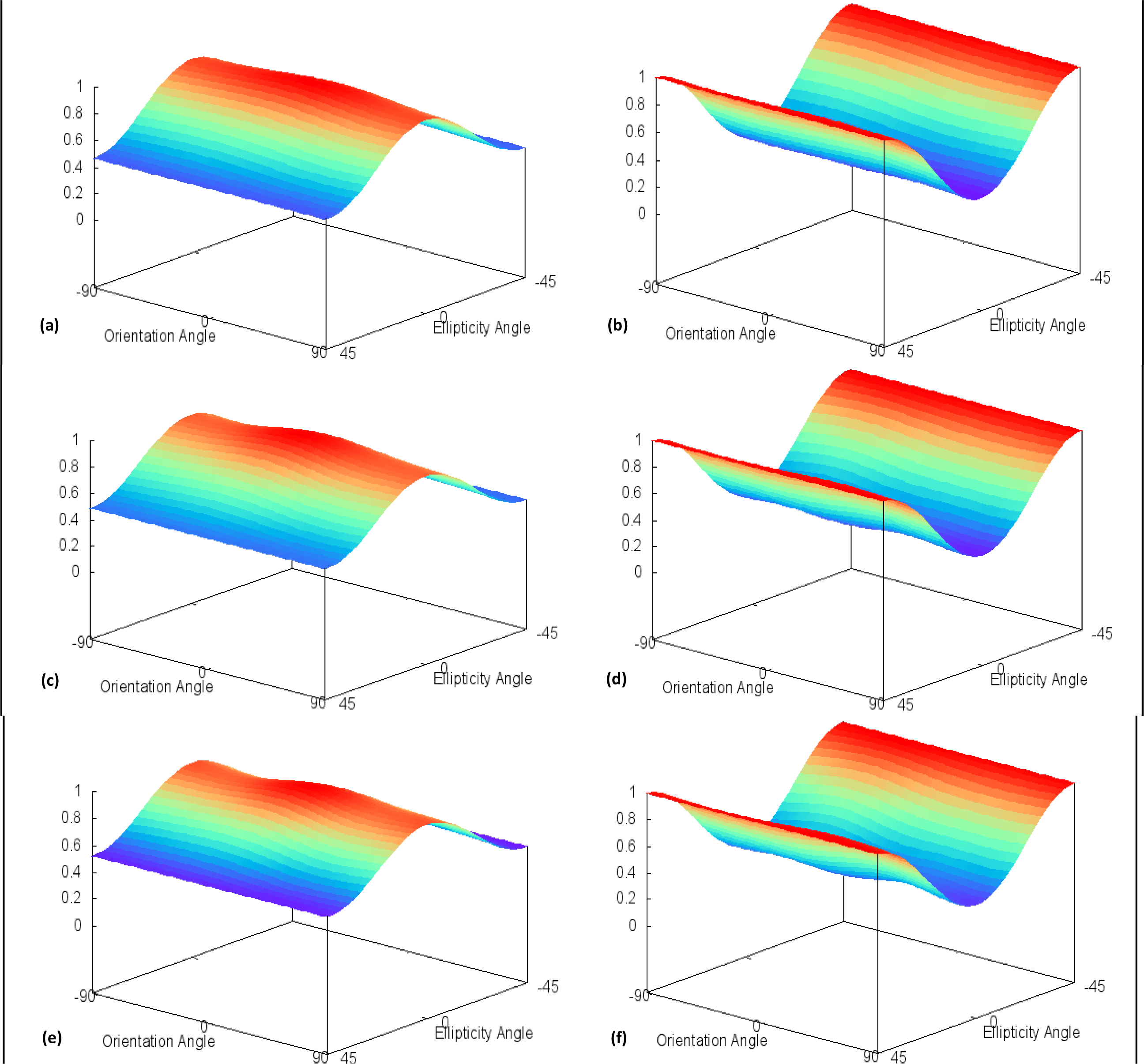
Nearly all co-polarized plots of the forest target (Figure 6) showed equal responses for HH and VV, which coincides with the similar backscatter intensities observed in Figure 4, as well as the response plots from a forest in San Francisco, CA, USA [24]. The relatively high pedestal height and flatness of the co-polarized signature indicate a high percentage of non-polarized return due to volume scattering of tree canopies. Additionally, the presence of volume scattering is supported by a moderate pedestal height and relatively high cross-pol response for the orthogonal orientation angles (−90°, 0°, +90°) and 0° ellipticity angle.
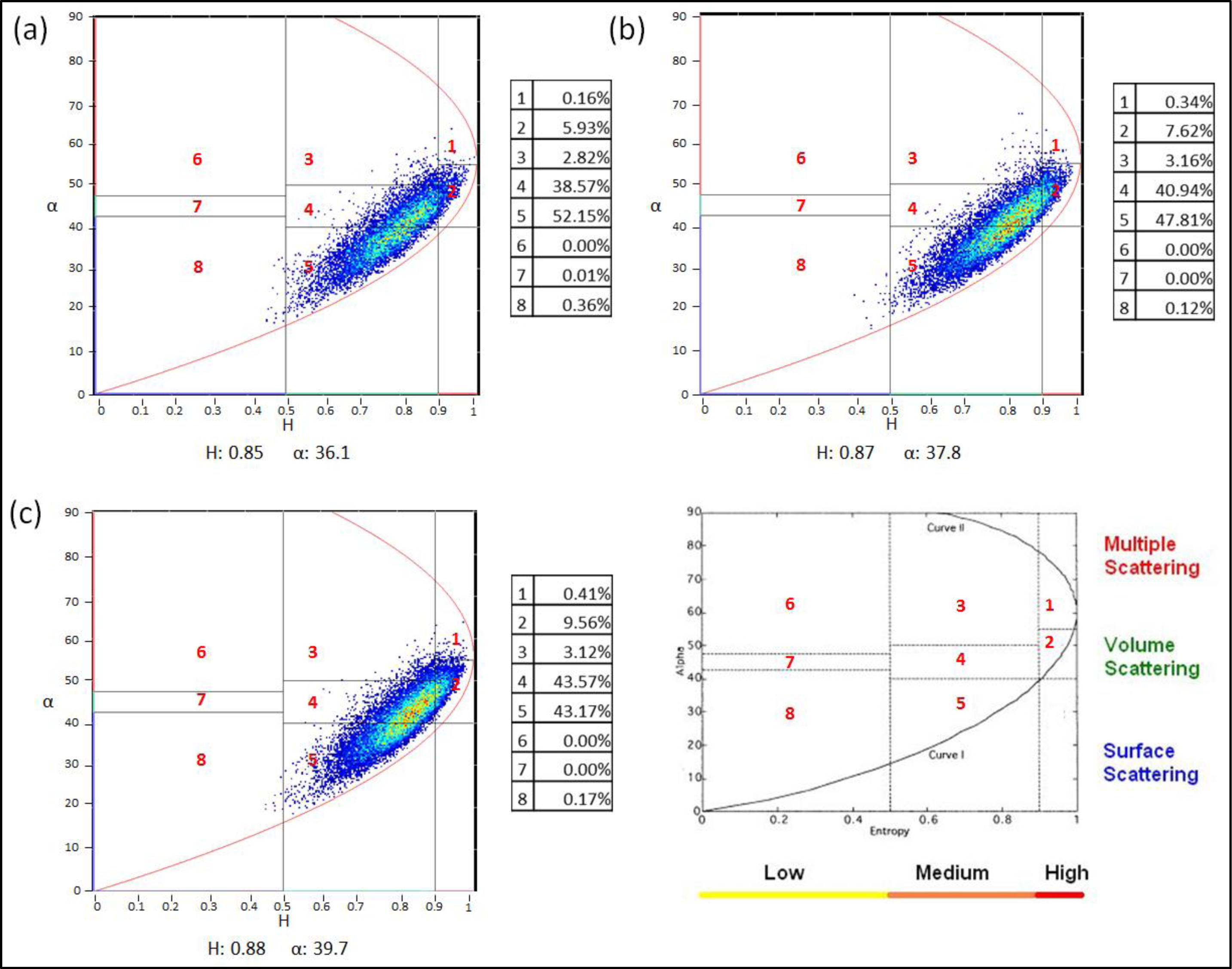
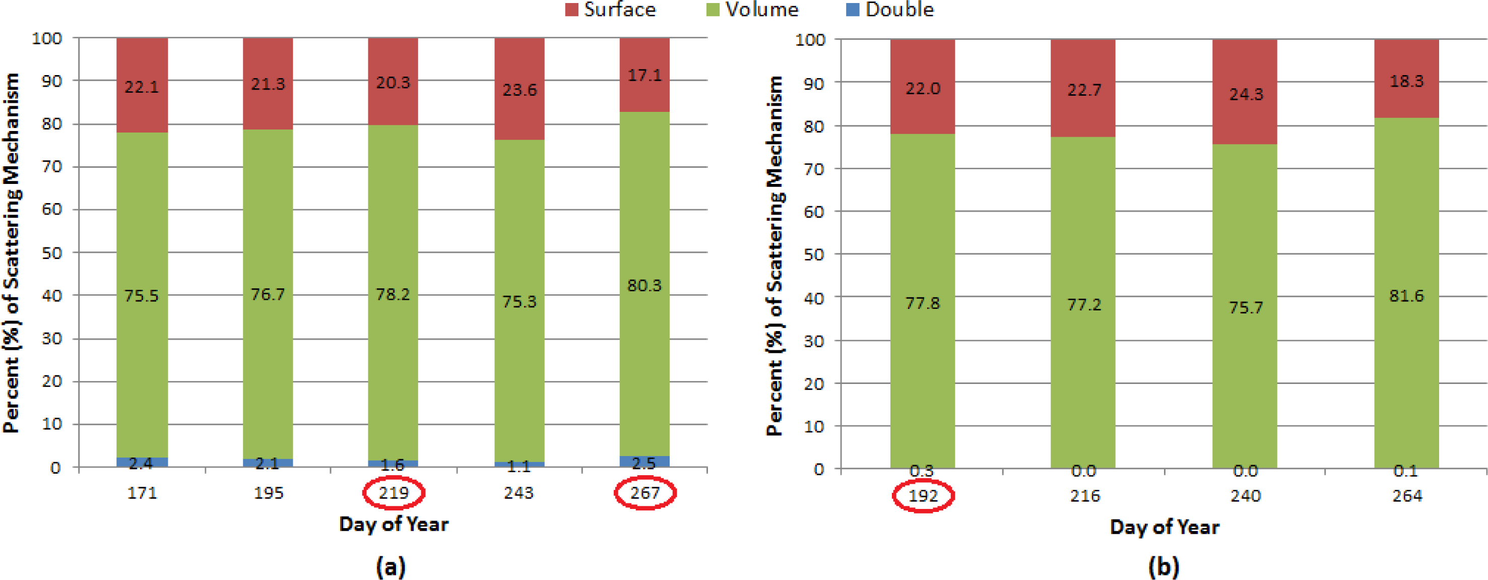
The Cloude-Pottier decompositions (Figure 7) split the forest target between zones 4 and 5, as the canopy is dense enough to produce surface (zone 5) scattering, while not so dense as not to prevent volume (zone 4) scattering. Unlike longer wavelengths such as L-band (25 cm), the C-band (5 cm) does not penetrate through dense forest canopies, and is instead scattered by leaf and branch elements before ever reaching the ground. For the Freeman-Durden decompositions (Figure 8), the scattering was attributed primarily to volume, never accounting for less than 75%, while the remainder was classified as surface scattering.

5.3.2. Urban

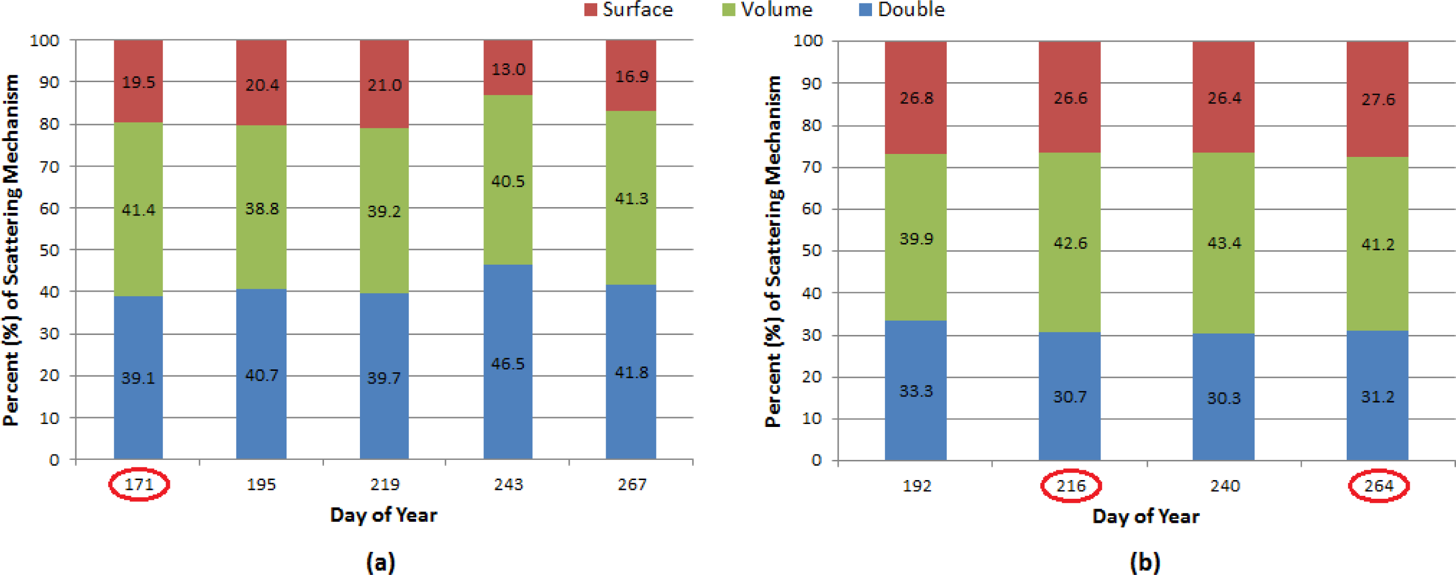
The urban polarization plots (Figure 9) also showed little variation relative to the change in incidence angle. Like van Zyl and Zebker [24], the signatures showed a dominance of HH over VV, which is typical of double-bounce scattering primarily from roads to the sides of buildings. However, the presence of vegetation within the urban area also contributed to volume scattering, shown as a moderate pedestal height and moderate cross-polarization return. The Cloude-Pottier decomposition (Figure 10) supports this deduction as the scattering mechanisms are evenly distributed between zones 3 (multiple), 4 (volume) and 5 (surface). Moreover, the Freeman-Durden decomposition (Figure 11) showed an almost equal contribution from the two dominant scattering mechanisms, volume and double-bounce scattering. This is often the case with such a large area having a variety of targets within it [24]. However it is important to note in the Freeman-Durden decompositions, the contribution of both surface and multiple scattering with respect to changing incidence angle. The shallow incidence angle acquisitions (FQ21) were more prone to double-bounce and thus multiple scattering is given a larger weight, whereas the steeper incidence angle (FQ7) was more typical of surface scattering.

5.3.3. Surface Water

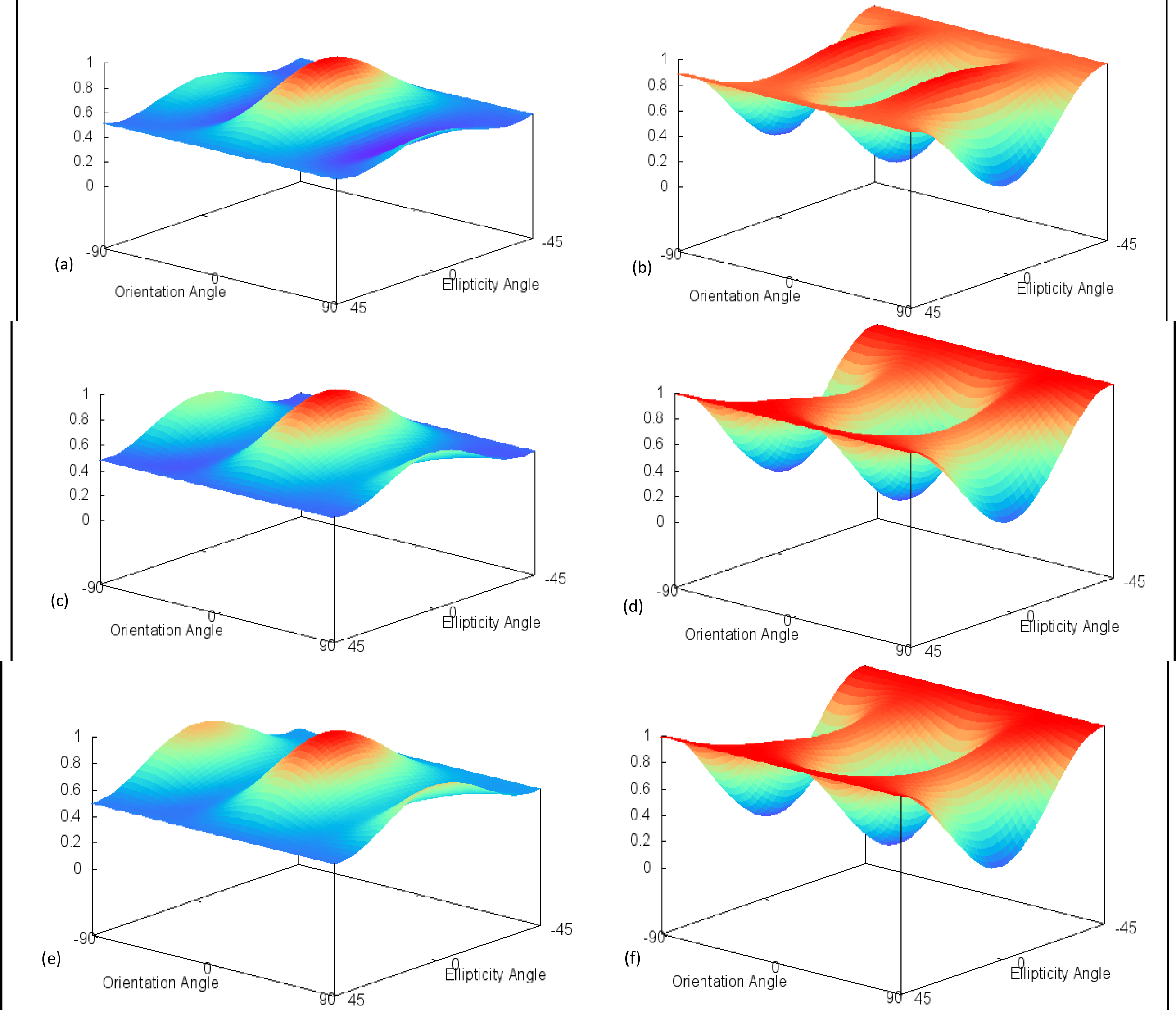
Unlike the forest and urban targets, the polarization response plots of the Lake Nipissing water targets (Figure 12) varied considerably by acquisition date. On 20 June (day 171), the response plot (Figure 12a) indicated a high return for both HH and VV scattering, as well as a large pedestal height. While normally indicative of volume scattering, it is evident from Figure 4 that the HV intensity was very close to the noise floor on this date, countering the possibility of volume scattering. A similar co-polarized response was observed by Nunziata et al. [31] in their study of marine oil slicks and its dampening of Bragg scattering. Relating back to Table 1, wind was non-existent at the time of acquisition, and therefore the water surface was flat enough to act as a specular reflector, much like the oil covered sea surface. Again referring back to Table 1, we can see that higher wind speeds were present during the shallow incidence angle acquisition on 7 August (day 219). This led to the co-polarized response to be more typical of the open water responses described by van Zyl and Zebker [24], with a high VV return over the lost HH, due to the wind-generated rougher surface. All steep incidence angle responses displayed very similar results with a higher HH return relative to the shallow incidence angle. This would indicate that the steep incidence angle response is influenced more by the signal being perpendicular to the target and less by wind activity.
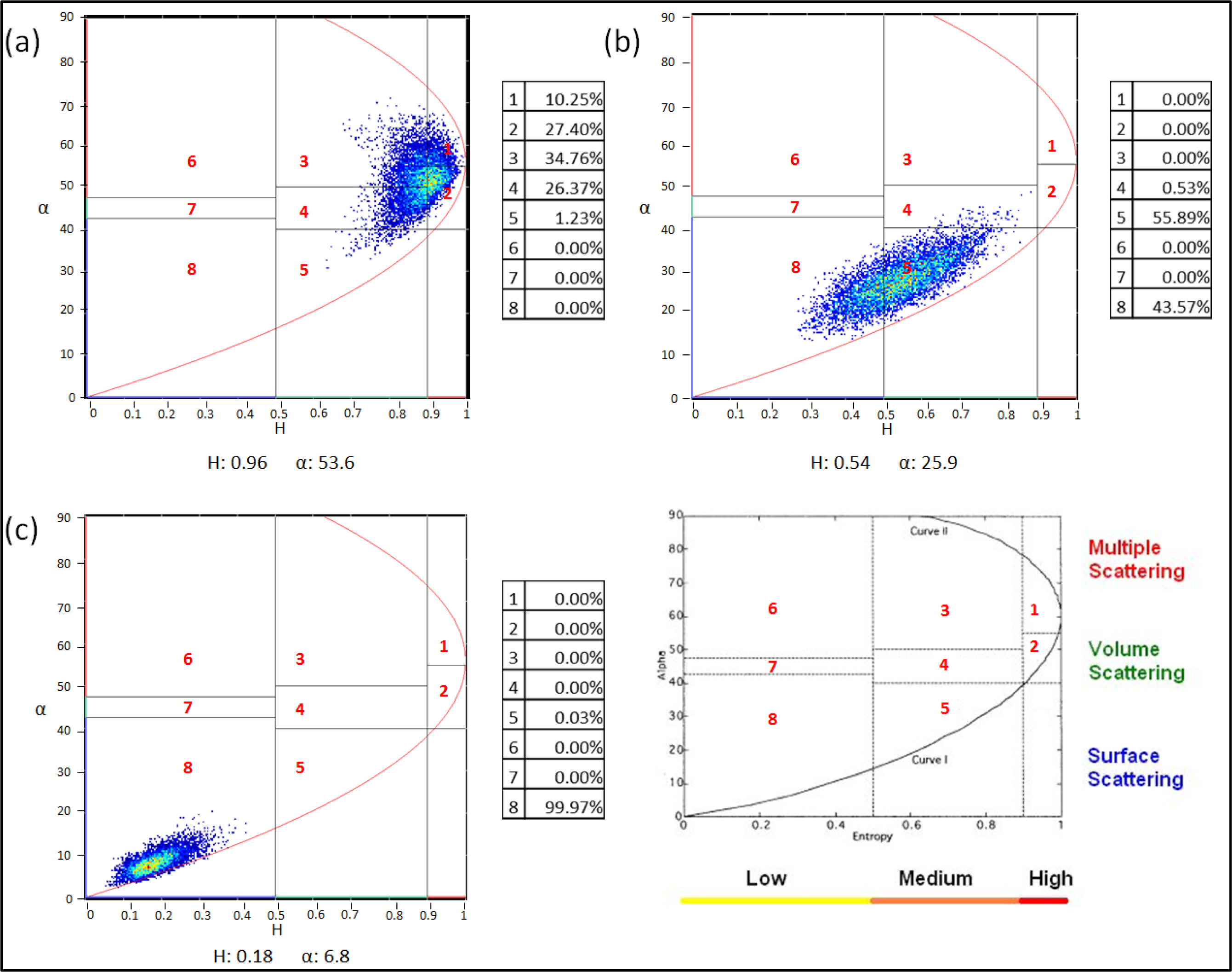
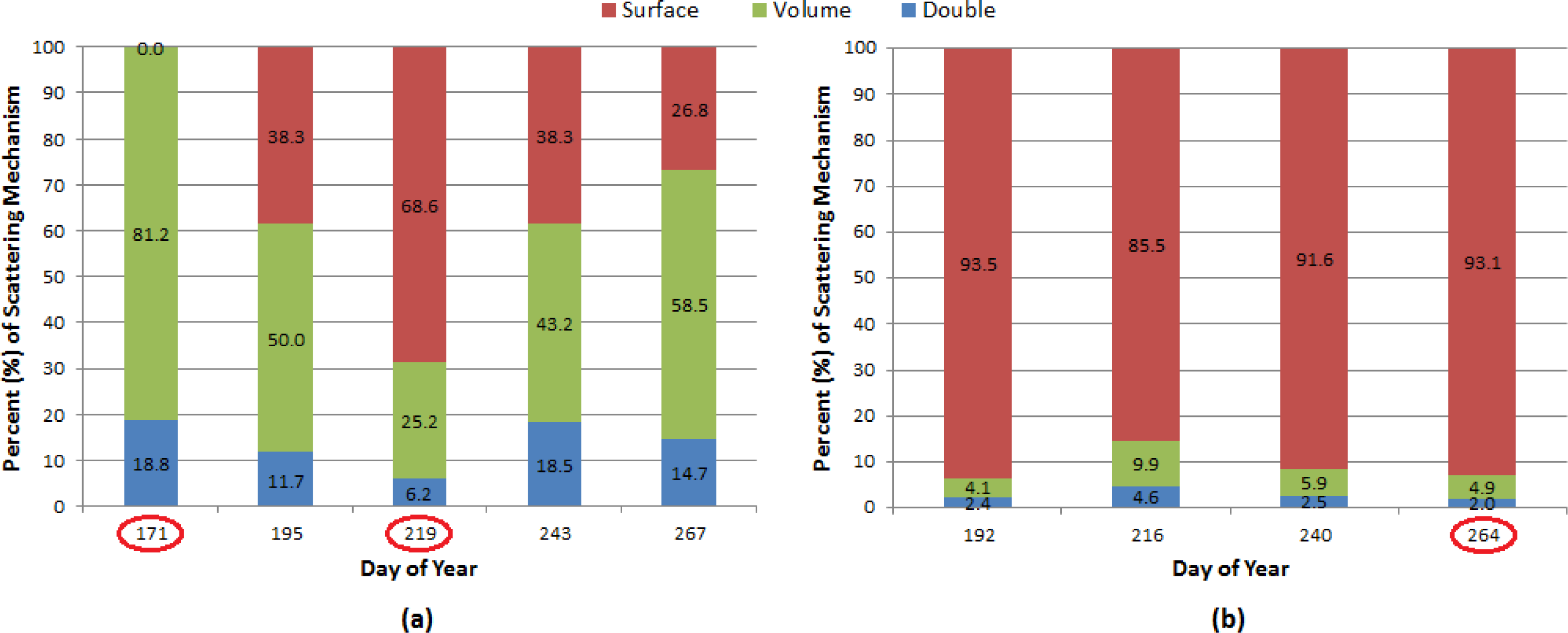
With the exception of the 20 June result (again, due to the absence of wind), many of the decompositions (Figures 13 and 14) accurately classified the appropriate scattering mechanism for water. For the Cloude-Pottier decomposition, open water was typically identified in zones 5 and 8. For the Freeman-Durden decomposition, the main contributors were surface and volume scattering. The high volume scattering contribution for shallow incidence angle acquisitions is likely associated to low-wind conditions leading to all three polarization intensities being found near the noise floor. Because the method of calculating the scattering mechanisms is relatively dependent on comparing the ratio of each return, a larger component was classified as volume scattering. This type of misinterpretation was also documented by Freeman and Durden [7] in their study of open water in Belize. On the other hand, steep incidence angle decompositions were much improved with respect to surface scattering contributions.

5.3.4. Marsh Wetlands

As stated in Section 5.1., wetland responses were heavily influenced by incidence angle. In Figure 15a,c, it is clear that the shallow and steep incidence angles produce very different co-polarized responses. The 20 June (day 171) co-polarization response (Figure 15a) indicates a strong VV backscatter in comparison to HH, likely due to a lack of emergent vegetation, allowing for considerable specular reflection of the HH. Conversely, the 4 August (day 216) co-polarization response (Figure 15c) shows strong HH return compared to VV, likely due to the steep incidence angle as well as enhanced double-bounce due to the plants emerging from the water surface. The emergent vegetation may also be the cause for high HH in shallow incidence angle acquisitions creating an ideal double-bounce target (Figure 15e). All cross-pol responses show little variation in terms of shape as orthogonal orientation angles have moderate backscatter. However, increasing pedestal heights were observed with the growth of the vegetation, indicating a stronger depolarizing target. It should also be mentioned that while wind conditions greatly influenced the response of water, wind speeds were not strong enough to lodge the vegetation or create large enough waves that would temporarily submerge the vegetation. Therefore, depending on the incidence angle, the responses remained similar over the course of the summer.
The Cloude-Pottier decompositions (Figure 16) classify the wetland target primarily in zone 6 (multiple scattering). As vegetation emerged, the entropy (i.e., disorder or randomness) of the target increased, thus the cluster shifted toward zone 3 (multiple scattering) and 4 (volume) for some dates. Moreover, the Freeman-Durden decomposition (Figure 17) overwhelmingly identifies double-bounce as the major scattering mechanism for all nine dates. The contribution of volume scattering in the Freeman-Durden decompositions also increased over time as the vegetation became more prominent.

6. Conclusion

The wetland target typically dominated co-polarized backscatter intensities as a result of double-bounce, while forest and urban targets displayed relatively consistent backscatter values due to little variation in geometry over the course of the summer. The change in incidence angle and wind speed had the greatest effect on the backscatter of water, as significantly lower intensities were observed for the shallow incidence angle with no-wind conditions, a result of specular reflection. Co-polarized phase differences also varied little with respect to incidence angle, except for the urban target. In comparison with the steep incidence angle, which is almost perpendicular to the target, the shallow incidence angle allows for road-building (and vice versa) reflections to occur, thus causing a delay in one of the polarizations.
The polarization response plots of each land use provide a valuable method of displaying the scattering response for all possible transmit and receive orientations. Analysis of these signatures shows backscatter for forested areas exhibit a response with a high pedestal height, suggesting a large unpolarized return, likely due to branch and leaf scattering. The urban and wetland targets were typical of dihedral corner reflectors, or double-bounce, as a result of building-road, and water-vegetation reflections, respectively. Open water typically displayed a response of a smooth surface with some instances of rough surface as a result of waves. Furthermore, polarimetric decompositions have also shown to be quite useful as they offer greater insight into the scattering properties of a target. Again, the forest target was typical of volume scattering, while wetlands were primarily dominated by double-bounce interactions. The urban target contained a large variation of land covers with different geometries, and thus the scattering mechanisms were classified evenly across surface, volume and double-bounce. Finally, water, a relatively smooth target, was characterized as surface scattering.
When analyzed in conjunction with polarimetric response plots, the decompositions provide supporting data to confidently identify targets and their scattering mechanisms. The combined use of these methods provides a suitable process for land use/land cover monitoring in northern Ontario. Moreover, given cloud cover for the region, SAR data could provide accurate results regardless of atmospheric conditions.
Finally, it should be noted that several factors must be taken into consideration when examining radar imagery. It was observed that wind commonly affects the response of water, yet has little to no influence on the other targets. In the case of a strong storm event, these systems can create damaging winds and heavy precipitation that could influence the polarimetric response of these targets to a great degree. However, weather events of this magnitude are rare for this region, and therefore were of no concern during this investigation. Given the temperate climate (i.e., distinct seasons) for this region, it is also important to consider phenological changes in the mixed forest and the presence of lake ice when selecting radar imagery of northern Ontario for land cover applications.

remotesensing-06-02372-s001.pdf

Acknowledgments

We would like to thank Jeffrey H. Wilson for his assistance with in-field verification. Additional thanks to Mark Wachowiak of Nipissing University, Steven Roberge of Ferme Roberge and all members of the West Nipissing branch of the Ontario Soil and Crop Improvement Association for their support during this investigation. Funding was provided through a grant from the Northern Ontario Heritage Fund Corporation of Canada (project # 920161). Finally, we would like to thank the four anonymous reviewers for their comments and suggestions.

Authors Contributions

Jeffrey W. Cable is the principal author of this manuscript having written the majority of the manuscript and contributing at all phases of the investigation. The other co-authors contributed in the field logistics, the field design, the selection and interpretation of the methods and contributed some portions of the written manuscript. The order of the authors reflects their level of contribution.

Conflicts of Interest

The authors declare no conflict of interest.

References

  1. Touzi, R.; Deschamps, A.; Rother, G. Wetland characterization using polarimetric RADARSAT-2 capability. Can. J. Remote Sens 2007, 33, S56–S67. [Google Scholar]
  2. Koch, M.; Schmid, T.; Reyes, M.; Gumuzzio, J. Evaluating full polarimetric C-and L-band data for mapping wetland conditions in a semi-arid environment in Central Spain. IEEE J. Sel. Top. Appl. Earth Obs. Remote Sens 2012, 5, 1033–1044. [Google Scholar]
  3. McNairn, H.; Shang, J.; Champagne, C.; Jiao, X. TERRASAR-X and RADARSAT-2 for Crop Classification and Acreage Estimation. Proceedings of the 2009 IEEE International Geoscience and Remote Sensing Symposium, Cape Town, South Africa, 12–17 July 2009.
  4. Qi, Z.; Yeh, A.G.; Li, X.; Lin, Z. A novel algorithm for land use and land cover using RADARSAT-2 polarimetric SAR data. Remote Sens. Environ 2012, 118, 21–39. [Google Scholar]
  5. Skriver, H.; Svendsen, M.T.; Thomsen, A.G. Multitemporal C- and L-band polarimetric signatures of crops. IEEE Trans. Geosci. Remote Sens 1999, 37, 2413–2429. [Google Scholar]
  6. Canada Centre for Remote Sensing. Advanced Radar Polarimetry Tutorial. 2013. Available online: http://www.nrcan.gc.ca/earth-sciences/geography-boundary/remote-sensing/radar/1893 (accessed on 25 August 2011).
  7. Freeman, A.; Durden, S.L. A three-component scattering model for polarimetric SAR data. IEEE Trans. Geosci. Remote Sens 1998, 36, 963–973. [Google Scholar]
  8. McNairn, H.; Shang, J.; Jiao, X.; Champagne, C. The contribution of ALOS PALSAR multipolarization and polarimetric data to crop classification. IEEE Trans. Geosci. Remote Sens 2009, 47, 3981–3992. [Google Scholar]
  9. Cloude, S.R.; Pottier, E. An entropy classification scheme for land applications of polarimetric SAR data. IEEE Trans. Geosci. Remote Sens 1997, 35, 68–78. [Google Scholar]
  10. Pottier, E.; Lee, J.S. Application of the H/A/α Polarimetric Decomposition Theorem for Unsupervised Classification of Fully Polarimetric SAR Data Based on the Wishart Distribution. Proceedings of the SAR Workshop—CEOS Working Group on Calibration and Validation, Toulouse, France, 26–29 October 1999; pp. 335–340.
  11. Pellizzeri, T.M. Classification of polarimetric SAR images of suburban areas using joint annealed segmentation and H/A/α polarimetric decomposition. ISPRS J. Photogramm. Remote Sens 2007, 58, 55–70. [Google Scholar]
  12. Bugden, J.L.; Pattey, E.; McNairn, H. Classification of crop and soil homogenous zones using multipolarization C-band SAR. Can. J. Remote Sens 2009, 35, 130–140. [Google Scholar]
  13. Li, K.; Brisco, B.; Yun, S. Polarimetric decomposition with RADARSAT-2 for rice mapping and monitoring. Can. J. Remote Sens 2012, 38, 169–179. [Google Scholar]
  14. Van Zyl, J.J.; Zebker, H.A.; Elachi, C. Imaging radar polarization signatures: Theory and observations. Radio Sci 1987, 22, 529–543. [Google Scholar]
  15. Webber, L.R.; Hoffman, D.W. Origin, Classification and Use of Ontario Soils; Ontario Department of Agriculture and Food: Toronto, ON, Canada, 1970; p. 58. [Google Scholar]
  16. The Corporation of the Municipality of West Nipissing. Agriculture in West Nipissing. Available online: http://www.westnipissingouest.ca/agriculture.html (accessed on 26 April 2012).
  17. Kershaw, L. Trees of Ontario; Lone Pine Publishing: Edmonton, AB, Canada, 2001. [Google Scholar]
  18. Pinto, F.; Rouillard, D.; Sobze, J.M.; Ter-Mikaelian, M. Validating tree species composition in forest resource inventory for Nipissing forest, ON, Canada. For. Chron 2007, 83, 247–251. [Google Scholar]
  19. Statistics Canada. Available online: http://www12.statcan.gc.ca/census-recensement/2011/dp-pd/prof/index.cfm (accessed on 13 May 2013).
  20. Legasy, K.; LaBelle-Beadman, S.; Chambers, B. Forest Plants of Northeastern Ontario; Lone Pine Publishing: Edmonton, AB, Canada, 1995. [Google Scholar]
  21. Ontario Ministry of Natural Resources. Cache Bay Wetland Conservation Reserve (C171); Ontario Ministry of Natural Resources: North Bay, ON, Canada, 2003. [Google Scholar]
  22. Jiao, X.; McNairn, H.; Shang, J.; Pattey, E.; Liu, J.; Champagne, C. The sensitivity of RADARSAT-2 polarimetric SAR data to corn and soybean leaf area index (LAI). Can. J. Remote Sens 2011, 37, 69–81. [Google Scholar]
  23. Boerner, W.M.; Mott, H.; Luneburg, E.; Livingstone, C.; Brisco, B.; Brown, R.J.; Patterson, J.S. Polarimetry in Radar Remote Sensing: Basic and Applied Concepts. In Manual of Remote Sensing: Principles and Applications of Imaging Radar, 3rd ed; Henderson, F.M., Lewis, A.J., Eds.; John Wiley and Sons: Toronto, ON, Canada, 1998; Volume 2, pp. 271–356. [Google Scholar]
  24. Van Zyl, J.J.; Zebker, H.A. Imaging Radar Polarimetry. In Progress in Electromagnetics Research 3: Polarimetric Remote Sensing; Kong, J.A., Ed.; Elsevier: New York, NY, USA, 1990; pp. 277–326. [Google Scholar]
  25. Staples, G. Understanding SAR Polarimetry; MDA Geospatial Services: Richmond, BC, Canada, 2007. [Google Scholar]
  26. Ulaby, F.T.; Held, D.; Dobson, M.C.; McDonald, K.C. Relating polarization phase difference of SAR signals to scene properties. IEEE Trans. Geosci. Remote Sens 1987, 25, 83–92. [Google Scholar]
  27. Henderson, F.M.; Xia, Z. Radar Applications in Urban Analysis, Settlement Detection and Population Estimation. In Manual of Remote Sensing: Principles and Applications of Imaging Radar, 3rd ed; Henderson, F.M., Lewis, A.J., Eds.; John Wiley and Sons: Toronto, ON, Canada, 1998; Volume 2, pp. 733–768. [Google Scholar]
  28. Leckie, D.G. Forestry Applications Using Imaging Radar. In Manual of Remote Sensing: Principles and Applications of Imaging Radar, 3rd ed; Henderson, F.M., Lewis, A.J., Eds.; John Wiley and Sons: Toronto, ON, Canada, 1998; Volume 2, pp. 435–510. [Google Scholar]
  29. Raney, R.K. Radar Fundamentals: Technical Perspective. In Manual of Remote Sensing: Principles and Applications of Imaging Radar, 3rd ed; Henderson, F.M., Lewis, A.J., Eds.; John Wiley and Sons: Toronto, ON, Canada, 1998; Volume 2, pp. 9–130. [Google Scholar]
  30. McNairn, H.; Duguay, C.; Brisco, B.; Pultz, T.J. The effect of soil and crop residue characteristics on polarimetric radar response. Remote Sens. Environ 2002, 80, 308–320. [Google Scholar]
  31. Nunziata, F.; Migliaccio, M.; Gambardella, A. Pedestal height for sea oil slick observation. IET Radar Sonar Naviga 2011, 5, 103–110. [Google Scholar]
Figure 1. Study location within the municipality of West Nipissing, Ontario displayed on a WorldView-2 image acquired on 2 July 2011.
Remotesensing 06 02372f1
Figure 2. Location of non-agricultural targets shown on a RADARSAT-2 image (R: HH, G: HV, B: VV) taken 4 August 2011 in West Nipissing, Ontario.
Remotesensing 06 02372f2
Figure 3. Flow diagram of processing and extraction methodology.
Remotesensing 06 02372f3
Figure 4. HH (Top), HV (Middle), and VV (Bottom) backscatter intensities for 41° (Left) and 26° (Right) incidence angles of land cover targets based on RADARSAT-2 fine quad beam modes.
Remotesensing 06 02372f4
Figure 5. Co-polarized (HH-VV) phase difference for RADARSAT-2 41° (Left) and 26° (Right) incidence angles of land cover targets.
Remotesensing 06 02372f5
Figure 6. Forest co- (Left) and cross-polarization (Right) polarimetric response plots based on RADARSAT-2 fine-quad beam modes for 11 July (a,b); 7 August (c,d); and 24 September (e,f).
Remotesensing 06 02372f6
Figure 7. Forest Cloude-Pottier H/α decomposition based on RADARSAT-2 fine-quad beam modes for (a) 11 July; (b) 7 August; and (c) 24 September.
Remotesensing 06 02372f7
Figure 8. Forest Freeman-Durden decomposition for (a) 41° and (b) 26° incidence angles based on RADARSAT-2 fine-quad beam modes. Note that circled days coincide with polarization response plot and Cloude-Pottier decomposition dates.
Remotesensing 06 02372f8
Figure 9. Urban co- (Left) and cross-polarization (Right) polarimetric response plots based on RADARSAT-2 fine-quad beam modes for 20 June (a,b); 4 August (c,d); and 21 September (e,f).
Remotesensing 06 02372f9
Figure 10. Urban Cloude-Pottier H/α decomposition based on RADARSAT-2 fine-quad beam modes for (a) 20 June; (b) 4 August; and (c) 21 September.
Remotesensing 06 02372f10
Figure 11. Urban Freeman-Durden decomposition for (a) 41° and (b) 26° incidence angles based on RADARSAT-2 fine-quad beam modes. Note that circled days coincide with polarization response plot and Cloude-Pottier decomposition dates.
Remotesensing 06 02372f11
Figure 12. Surface water co- (Left) and cross-polarization (Right) polarimetric response plots based on RADARSAT-2 fine-quad beam modes for 20 June (a,b); 7 August (c,d); and 21 September (e,f).
Remotesensing 06 02372f12
Figure 13. Surface water Cloude-Pottier H/α decomposition based on RADARSAT-2 fine-quad beam modes for (a) 20 June; (b) 7 August; and (c) 21 September.
Remotesensing 06 02372f13
Figure 14. Surface water Freeman-Durden decomposition for (a) 41° and (b) 26° incidence angles based on RADARSAT-2 fine-quad beam modes. Note that circled days coincide with polarization response plot and Cloude-Pottier decomposition dates.
Remotesensing 06 02372f14
Figure 15. Wetlands co- (Left) and cross-polarization (Right) polarimetric response plots based on RADARSAT-2 fine-quad beam modes for 20 June (a,b); 4 August (c,d); and 24 September (e,f).
Remotesensing 06 02372f15
Figure 16. Wetlands Cloude-Pottier H/α decomposition based on RADARSAT-2 fine-quad beam modes for (a) 20 June; (b) 4 August; and (c) 24 September.
Remotesensing 06 02372f16
Figure 17. Wetlands Freeman-Durden decomposition for (a) 41° and (b) 26° incidence angles based on RADARSAT-2 fine-quad beam modes. Note that circled days coincide with polarization response plot and Cloude-Pottier decomposition dates.
Remotesensing 06 02372f17
Table 1. 2011 RADARSAT-2 acquisitions.
Acquisition (mm-dd-yyyy)Day of YearPolarization (Beam Mode)Resolution (m)Incidence Angle (°)Orbit (Look Direction)Wind Speed (km/h)
06-20-2011171Polarimetric (FQ21)1041Ascending (Right)0
07-11-2011192Polarimetric (FQ7)1026Ascending (Right)6
07-14-2011195Polarimetric (FQ21)1041Ascending (Right)6.8
08-04-2011216Polarimetric (FQ7)1026Ascending (Right)4
08-07-2011219Polarimetric (FQ21)1041Ascending (Right)9.7
08-28-2011240Polarimetric (FQ7)1026Ascending (Right)5.4
08-31-2011243Polarimetric (FQ21)1041Ascending (Right)6.8
09-21-2011264Polarimetric (FQ7)1026Ascending (Right)10.8
09-24-2011267Polarimetric (FQ21)1041Ascending (Right)0
*Wind speed is an average over a five minute period with a thirty second sampling interval.