Transformation Model with Constraints for High-Accuracy of 2D-3D Building Registration in Aerial Imagery
Abstract
:1. Introduction
- (1)
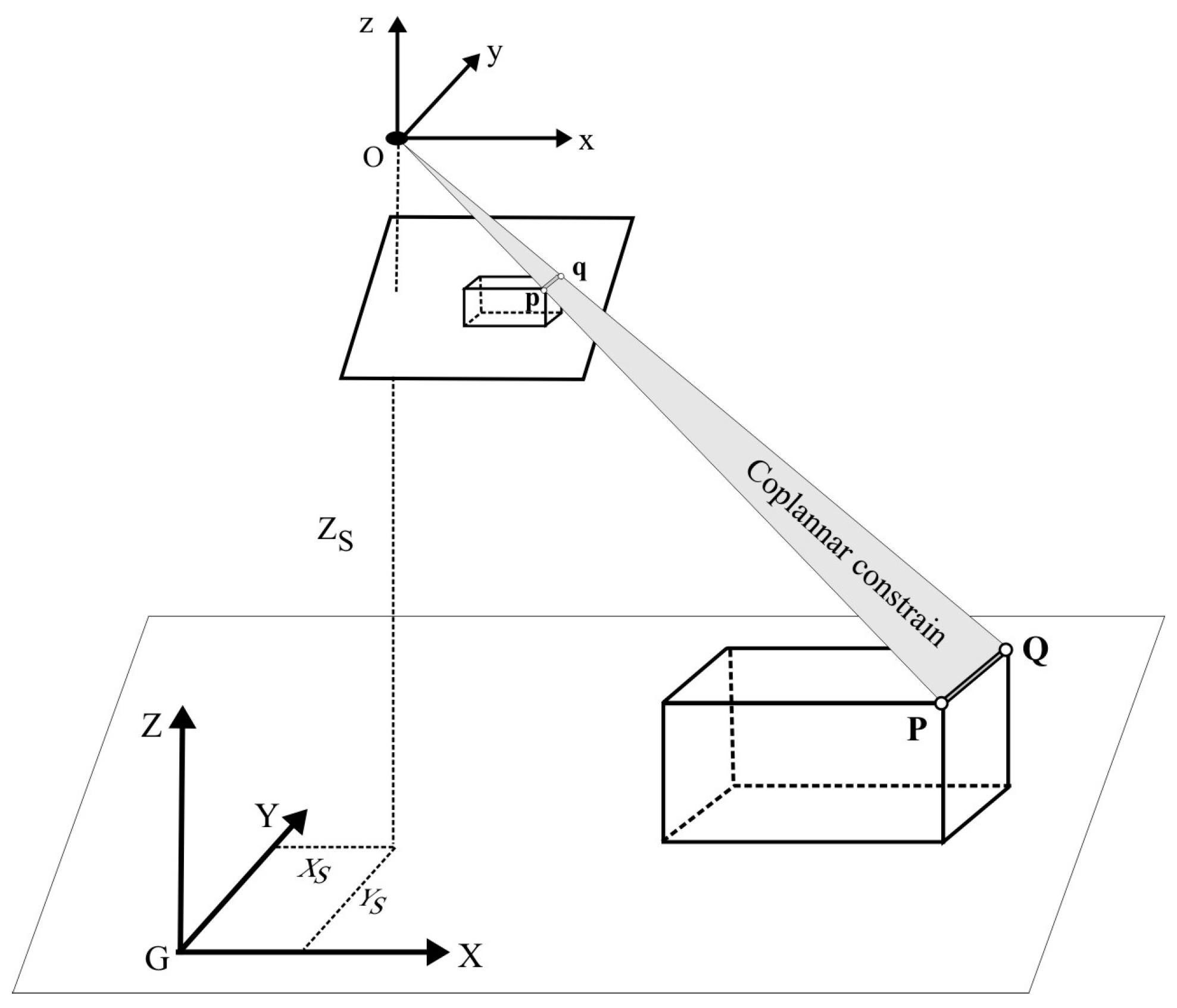
- Co-planar condition: The photogrammetric center, a line in the object coordinate system and the corresponding line in the image coordinate system are in the same plane.
- (2)
- Perpendicular condition: The constraint requires that if two lines are perpendicular in the object coordinate system, their projections are perpendicular in the image coordinate system.
2. Related Work
- Feature detection: Existing methods can be classified into feature-based or intensity-based methods. Feature-based methods use point features, linear features and areal features extracted from both the 3D urban surface/building model and 2D imagery as the common feature pairs and then align the corresponding feature pairs via a transform model. This method has been widely applied in computer vision [18,19,20,21,22,23] and medical image processing [24,25]. Intensity-based methods utilize the intensity-driven information, such as texture, reflectance, brightness, and shadow, to achieve high-accuracy in 2D-3D registration [11,13,26]. These features, which are called ground control points (GCPs) in remote sensing, can be detected manually or automatically.
- Feature matching: The relationship between the features detected from the two images is established. Different feature similarity measures are used for the estimation.
- Transform model estimation: The transform type and its parameters between two images are estimated by certain mapping functions based on the previously-established feature correspondence.
- Image resampling and transformation: The slave image is resampled and transformed into the frame of the reference image, according to the transformation model and interpolation technique.
3. Rigorous Transformation Model
3.1. Coplanar Condition
3.2. Perpendicular Condition
3.3. Solution of Registration Parameters
3.4. Accuracy Evaluation
3.5. Discussion
3.5.1. Coplanar and Collinear Constraint
- Under the collinear constraint, three points B′, E′, C′ are considered to lie on a line in object space. However, due to the incomplete camera calibration in practice, their projections b′, e′, c′ cannot be guaranteed to lie on a line in image space. This implies that the collinear constraint condition ensures their collinearity only in object space, but it does not ensure their collinearity in image space.
- If the image is completely free of distortion after processing (this is definitely impossible.), their projections b′, e′, c′ in image space should lie on a line; i.e., their projections also meet the collinear constraint condition in image space. Under this ideal condition, the collinear constraint is consistent with the coplanar constraint. In other words, the collinearity and coplanar constraint condition is highly correlated if they are simultaneously considered in a formula.
- Because the camera lens cannot be completely calibrated, the residue of image distortion still remains even though a very high accuracy of camera calibration is achieved. This fact results in a line in object space being distortion free, but its corresponding image still contains distortion in image space. That is, the coplanar constraint combines a line in object space with its corresponding one in image space, whereas the collinear constraint considers only a line in object space. Thus, the coplanar constraint condition is much stricter than the collinear constraint condition.
3.5.2. Perpendicular Constraint
4. Experiments and Analysis
4.1. Experimental Data
- Aerial images: The six aerial images, with two flight strips, at the end lap of approximately 65% and the side lap of 30%, were acquired using a Leica RC30 aerial camera at a nominal focal length of 153.022 mm on 17 April 2000 (see Figure 5). The flying height was 1650 m above the mean ground elevation of the imaged area. The aerial photos were originally recorded on film and later scanned into digital format at a pixel resolution of 25 μm.
- DSM dataset: The DSM in the central part of downtown Denver was originally acquired by LiDAR and then edited into grid format at a spacing of 0.6 m (Figure 6a). The DSM accuracy in planimetry and height was approximately 0.1 m and 0.2 m, respectively. The horizontal datum is Geodetic Reference System (GRS) 1980, and the vertical datum is North American Datum of 1983 (NAD83).
- CSG representation: With the given DSM (see Figure 6a), a 3D CSG (constructive solid geometry) model was utilized to represent the building individually. The CSG is a very mature method that uses a few basic primitives to create a complex surface or object by Boolean operators [38]. The details of the CSG method can be found in [6,38]. This paper proposes a three-level data structure to represent a building based on the given DSM data. The first level is 2D primitive representation, such as rectangle, circle, triangle or polygon, accompanied with their own parameters, including length, width, radius and the position of the point. The second level is 3D primitive representation, which is created by adding height information onto the 2D primitives. For example, by adding height information onto a rectangle (2D primitive), it becomes a cube (3D primitive); by adding height information onto a circle (2D primitive), it becomes a cylinder (3D primitive). In other words, cubes, cylinders, cones, pyramids, etc., are single 3D primitives. The third level is to create a 3D CSG representation of a building by combining multiple 3D primitives. During this process, a topological relationship is created, as well, so that building data can be easily retrieved and the geometric constraints proposed in this paper can be easily constructed. Meanwhile, the attributes (e.g., length, position, direction, grey) are assigned to each building (see Figure 6b).
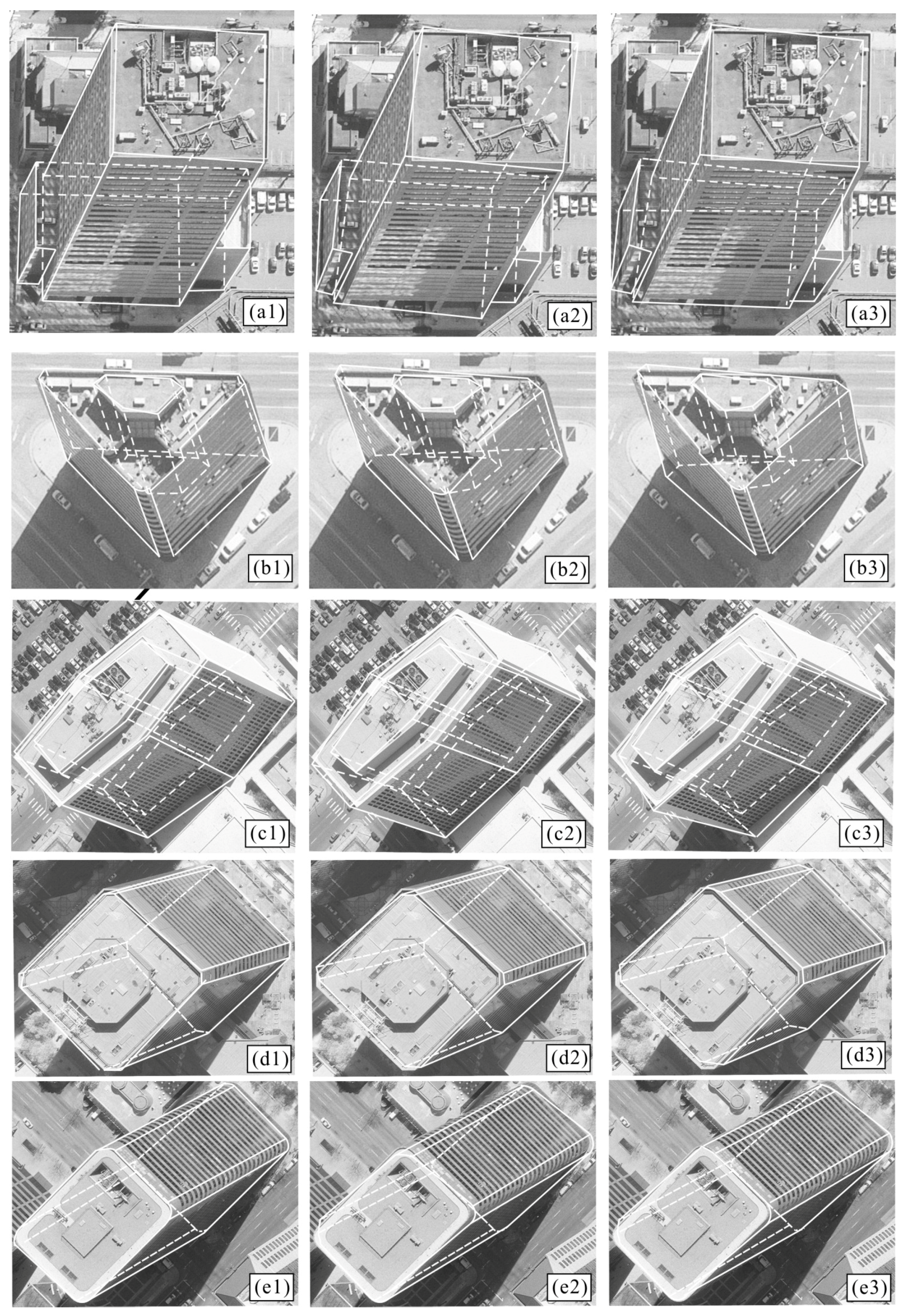
- Coordinate measurement of “GCPs” and checkpoints: In areas with numerous high buildings, it is impossible to find conventional photogrammetric targeted points as ground control points (GCPs). In this paper, the corner points of building roofs or bottoms are taken as “GCPs”. The 3D (XYZ) coordinates of “GCPs” are acquired from the DBM. The corresponding 2D image coordinates are automatically measured with Erdas/Imagine software. The first three “GCPs” are selected manually. First, we select their locations in DBM, and their 3D coordinates can be read directly. We then find the corresponding locations in the 2D images manually with Erdas/Imagine software. After that, all other “GCPs” can be automatically measured with Erdas/Imagine software. The 2D image coordinates of “GCP” selection and measurements are based on back-projection. The EOPs of each image are solved by the first three measured “GCPs”, and the 3D coordinates of the other corners of buildings are then back-projected onto the image plane, with which the 2D image coordinates are automatically measured (Figure 7a). The measurement accuracy of the 2D image coordinates is at the sub-pixel level. With the operation above, 321 points are measured, of which 232 points are taken as “GCPs” and 89 are used as checkpoints, which will be used to evaluate the final accuracy of 2D-3D registration (Figure 6a and Figure 7b).
4.2. Establishment of the Registration Model
4.3. Experimental Results
5. Accuracy Comparison and Analysis
5.1. Comparison of Theoretical Accuracy
5.2. Accuracy Comparison in 2D Space
6. Conclusions
Acknowledgments
Author Contributions
Conflicts of Interest
References
- Clarkson, M.J.; Rueckert, D.; Hill, D.L.; Hawkes, D.J. Using photo-consistency to register 2D optical images of the human face to a 3D surface model. IEEE Trans. Pattern Anal. Mach. Intell. 2001, 23, 1266–1280. [Google Scholar] [CrossRef]
- Liu, L.; Stamos, I. A systematic approach for 2D-image to 3D-range registration in urban environments. Comput. Vis. Image Underst. 2012, 116, 25–37. [Google Scholar] [CrossRef]
- Zhou, G.; Song, C.; Schickler, W. Urban 3D GIS from LIDAR and aerial image data. Comput. Geosci. 2004, 30, 345–353. [Google Scholar] [CrossRef]
- Christian, F.; Zakhor, A. An automated method for large-scale, ground-based city model acquisition. Int. J. Comput. Vis. 2004, 60, 5–24. [Google Scholar]
- Poullis, C.; You, S. Photorealistic large-scale urban city model reconstruction. IEEE Trans. Vis. Comput. Graph. 2009, 15, 654–669. [Google Scholar] [CrossRef] [PubMed]
- Zhou, G.; Chen, W.; Kelmelis, J. A Comprehensive Study on Urban True Orthorectification. IEEE Trans. Geosci. Remote Sens. 2005, 43, 2138–2147. [Google Scholar] [CrossRef]
- Zhou, G.; Uzi, E.; Feng, W.; Yuan, B. CCD camera calibration based on natural landmark. Pattern Recognit. 1998, 31, 1715–1724. [Google Scholar] [CrossRef]
- Zhou, G.; Xie, W.; Cheng, P. Orthoimage creation of extremely high buildings. IEEE Trans. Geosci. Remote Sens. 2008, 46, 4132–4141. [Google Scholar] [CrossRef]
- Brown, G. A survey of image registration techniques. ACM Comput. Surv. 1992, 24, 325–376. [Google Scholar] [CrossRef]
- Besl, J.; McKay, N. A method for registration of 3D shapes. IEEE Trans. Pattern Anal. Mach. Intell. 1992, 14, 239–256. [Google Scholar] [CrossRef]
- Maintz, B.; van den Elsen, P.; Viergever, M. 3D multimodality medical image registration using morphological tools. Image Vis. Comput. 2001, 19, 53–62. [Google Scholar] [CrossRef]
- Wang, S.; Tseng, Y.-H. Image orientation by fitting line segments to edge pixels. In Proceedings of the Asian Conference on Remote Sensing (ACRS), Kathmandu, Nepal, 25–29 November 2002.
- Zitová, B.; Flusser, J. Image registration methods: A survey. Image Vis. Comput. 2003, 21, 977–1000. [Google Scholar] [CrossRef]
- Salvi, J.; Matabosch, C.; Fofi, D.; Forest, J. A review of recent range image registration methods with accuracy evaluation. Image Vis. Comput. 2007, 25, 578–596. [Google Scholar] [CrossRef]
- Zhou, G.Q. Geo-referencing of video flow from small low-cost civilian UAV. IEEE Trans. Autom. Eng. Sci. 2010, 7, 156–166. [Google Scholar] [CrossRef]
- Santamaría, J.; Cordón, O.; Damas, S. A comparative study of state-of-the-art evolutionary image registration methods for 3D modeling. Comput. Vis. Image Underst. 2011, 115, 1340–1354. [Google Scholar] [CrossRef]
- Markelj, P.; Tomaževič, D.; Likar, B.; Pernuš, F. A review of 3D/2D registration methods for image-guided interventions. Med. Image Anal. 2012, 16, 642–661. [Google Scholar] [CrossRef] [PubMed]
- Bican, J.; Flusser, J. 3D rigid registration by cylindrical phase correlation method. Pattern Recognit. Lett. 2009, 30, 914–921. [Google Scholar] [CrossRef]
- Cordón, O.; Damas, S.; Santamaría, J. Feature-based image registration by means of the CHC evolutionary algorithm. Image Vis. Comput. 2006, 22, 525–533. [Google Scholar] [CrossRef]
- Chung, J.; Deligianni, F.; Hu, X.; Yang, G. Extraction of visual features with eye tracking for saliency driven 2D/3D registration. Image Vis. Comput. 2005, 23, 999–1008. [Google Scholar] [CrossRef]
- Fitzgibbon, W. Robust registration of 2D and 3D point sets. Image Vis. Comput. 2003, 21, 1145–1153. [Google Scholar] [CrossRef]
- Ding, L.; Goshtasby, A.; Satter, M. Volume image registration by template matching. Image Vis. Comput. 2001, 19, 821–832. [Google Scholar] [CrossRef]
- Hsu, L.Y.; Loew, M.H. Fully automatic 3D feature-based registration of multi-modality medical images. Image Vis. Comput. 2001, 19, 75–85. [Google Scholar] [CrossRef]
- Benameur, S.; Mignotte, M.; Parent, S.; Labelle, H.; Skalli, W.; de Guise, J. 3D/2D registration and segmentation of sclerotic vertebrae using statistical models. Comput. Med. Imaging Graph. 2003, 27, 321–337. [Google Scholar] [CrossRef]
- Gendrin, C.; Furtado, H.; Weber, C.; Bloch, C.; Figl, M.; Pawiro, S.A.; Bergmann, H.; Stock, M.; Fichtinger, G.; Georg, D. Monitoring tumor motion by real time 2D/3D registration during radiotherapy. Radiother. Oncol. 2012, 102, 274–280. [Google Scholar] [CrossRef] [PubMed]
- Zikic, D.; Glocker, B.; Kutter, O.; Groher, M.; Komodakis, N.; Kamen, A.; Paragios, N.; Navab, N. Linear intensity-based image registration by Markov random fields and discrete optimization. Med. Image Anal. 2010, 14, 550–562. [Google Scholar] [CrossRef] [PubMed]
- Huseby, B.; Halck, O.; Solberg, R. A model-based approach for geometrical correction of optical satellite images. Int. Geosci. Remote Sens. Symp. 1999, 1, 330–332. [Google Scholar]
- Shin, D.; Pollard, J.K.; Muller, J.P. Accurate geometric correction of ATSR images. IEEE Trans. Geosci. Remote Sens. 1997, 35, 997–1006. [Google Scholar] [CrossRef]
- Thepaut, O.; Kpalma, K.; Ronsin, J. Automatic registration of ERS and SPOT multisensor images in a data fusion context. For. Ecol. Manag. 2000, 128, 93–100. [Google Scholar] [CrossRef]
- Horaud, R. New methods for matching 3-D objects with single perspective view. IEEE Trans. Pattern Anal. Mach. Intell. 1987, 9, 401–412. [Google Scholar] [CrossRef] [PubMed]
- Suetens, P.; Fua, P.; Hanson, A.J. Computational strategies for object recognition. ACM Comput. Surv. 1992, 24, 5–61. [Google Scholar]
- Lafarge, F.; Descombes, X.; Zerubia, J.; Deseilligny, M. Structural approach for building reconstruction from a single DSM. IEEE Trans. Pattern Anal. Mach. Intell. 2010, 32, 135–147. [Google Scholar] [PubMed]
- Habib, A.; Morgan, M.; Lee, Y. Bundle adjustment with self-calibration using straight lines. Photogramm. Rec. 2002, 17, 635–650. [Google Scholar]
- Zhang, Z.; Deng, F.; Zhang, J.; Zhang, Y. Automatic registration between images and laser range data. In Processing of the SPIE MIPPR 2005: SAR and Multispectral Image Processing, Wuhan, China, 31 October–2 November 2005; Zhang, L., Zhang, J., Eds.; SPIE: Wuhan, China, 2005. [Google Scholar]
- Wolf, P.; Dewitt, B. Elements of Photogrammetry, 2nd ed.; McGraw-Hill Companies: New York, NY, USA, 2000. [Google Scholar]
- Triggs, B.; McLauchlan, P.; Hartley, R.; Fitzgibbon, A. Bundle adjustment—A modern synthesis. In Vision Algorithms: Theory and Practice; Triggs, B., Zisserman, A., Szeliski, R., Eds.; Springer-Verlag LNCS: Heidelberg, Germany, 1883. [Google Scholar]
- Lawson, C.L.; Hanson, R.J. Solving Least Squares Problems; Society for Industrial and Applied Mathematics: New Providence, NJ, USA, 1987. [Google Scholar]
- James, F. Constructive Solid Geometry, Computer Graphics: Principles and Practice; Addison-Wesley Professional: Upper Saddle River, NJ, USA, 1996; pp. 557–558. [Google Scholar]


| Methods | Lens Distortion Parameter | (pixel) | |||
|---|---|---|---|---|---|
| Registration Model | Control Primitives | k1 (×10−4) | ρ1 (×10−6) | ρ1 (×10−6) | |
| Traditional model | 12 points | 0.208 | −0.114 | 0.198 | 1.23 |
| Traditional model | 211 points | 0.301 | −0.174 | 0.222 | 1.09 |
| Our model | 32 points + constraints | 0.707 | −0.201 | 0.038 | 0.47 |
| Methods | Exterior Orientation Parameter | |||||||
|---|---|---|---|---|---|---|---|---|
| Registration Model | Registration Primitives | ϕ (arc) | ω (arc) | k (arc) | XS (ft) | YS (ft) | ZS (ft) | (pixel) |
| Traditional model | 12 points | 0.0104 | 0.0158 | −1.5503 | 3143007.3 | 1696340.4 | 9032.0 | 1.26 |
| Traditional model | 211 points | −0.0025 | −0.0405 | −1.5546 | 3143041.4 | 1696562.6 | 9070.7 | 1.02 |
| Our model | 32 points + constraints | −0.0017 | −0.0322 | −1.5544 | 3143041.2 | 1696533.4 | 9071.8 | 0.37 |
| Registration Models | Control Primitives | (pixel) | (pixel) |
|---|---|---|---|
| Conventional model | 12 points | 9.4 | 10.1 |
| Conventional model | 211 points | 5.2 | 6.7 |
| Proposed model | 32 points + constraints | 1.8 | 2.2 |
© 2016 by the authors; licensee MDPI, Basel, Switzerland. This article is an open access article distributed under the terms and conditions of the Creative Commons Attribution (CC-BY) license (http://creativecommons.org/licenses/by/4.0/).
Share and Cite
Zhou, G.; Luo, Q.; Xie, W.; Yue, T.; Huang, J.; Shen, Y. Transformation Model with Constraints for High-Accuracy of 2D-3D Building Registration in Aerial Imagery. Remote Sens. 2016, 8, 507. https://doi.org/10.3390/rs8060507
Zhou G, Luo Q, Xie W, Yue T, Huang J, Shen Y. Transformation Model with Constraints for High-Accuracy of 2D-3D Building Registration in Aerial Imagery. Remote Sensing. 2016; 8(6):507. https://doi.org/10.3390/rs8060507
Chicago/Turabian StyleZhou, Guoqing, Qingli Luo, Wenhan Xie, Tao Yue, Jingjin Huang, and Yuzhong Shen. 2016. "Transformation Model with Constraints for High-Accuracy of 2D-3D Building Registration in Aerial Imagery" Remote Sensing 8, no. 6: 507. https://doi.org/10.3390/rs8060507
APA StyleZhou, G., Luo, Q., Xie, W., Yue, T., Huang, J., & Shen, Y. (2016). Transformation Model with Constraints for High-Accuracy of 2D-3D Building Registration in Aerial Imagery. Remote Sensing, 8(6), 507. https://doi.org/10.3390/rs8060507


