
A Review on Microstructural Features and Mechanical Properties of Wheels/Rails Cladded by Laser Cladding

Abstract
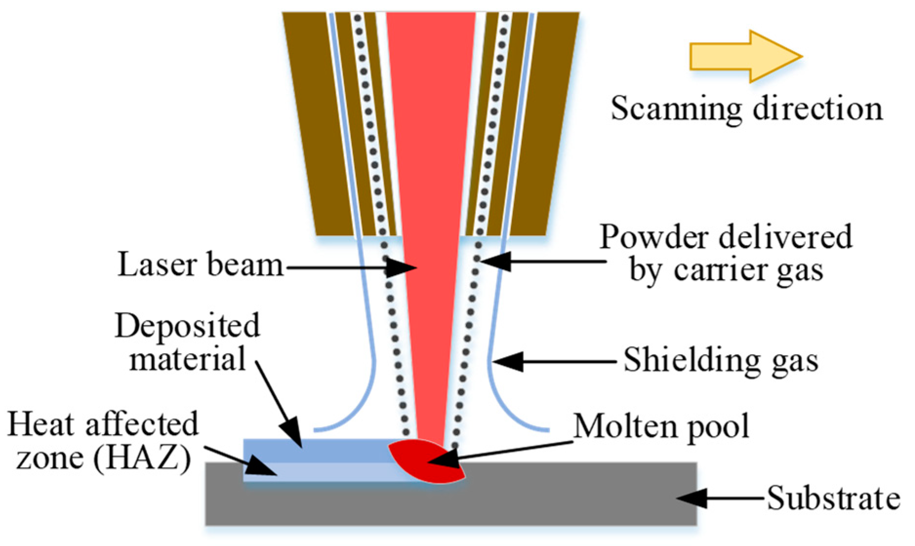
:1. Introduction
2. Effects of Process Parameters on Geometrical and Microstructural Characteristics
2.1. Geometrical Features of the Clad
2.2. Microstructure
2.3. Microhardness
2.4. Residual Stress
3. Mechanical Characteristics
3.1. Tensile and Bending Properties
3.2. Fatigue Resistance
4. Process Optimization for Enhanced Mechanical Properties
5. Conclusions
- (1)
- The effects of processing parameters (e.g., laser power, scanning speed, powder feed rate, etc.) on the cladded layer have been reviewed, indicating that a proper selection of process parameters contributes to controlling the geometry of the cladded layer, obtaining the fine dendritic morphology and reducing the defects (heating bubbles, for instance).
- (2)
- The overview images of all microstructures would show an HAZ dilution zone, coarse-grained zone, and fine-grained microstructure zone, followed by an inter-critical or sub-critical HAZ adjacent to the base material based on the difference of the substrate. In addition, the brittle martensitic structures, which are harmful to the mechanical properties, would be formed in the HAZ.
- (3)
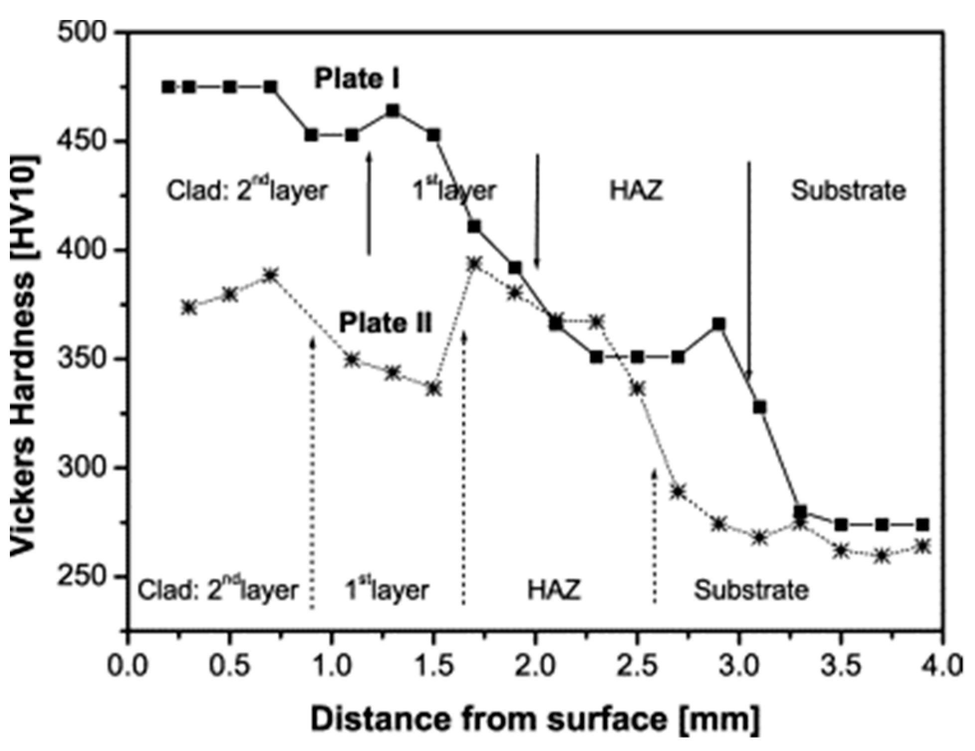
- With an increase of depth, the hardness of the cladding coatings decreases gradually along the cladding layer and finally close to the hardness of substrate. However, the HAZ region would present much higher hardness than that of the substrate and coatings because of the existence of the martensite structure. With the difference of the cladding material, the distribution of residual stress will be different.
- (4)
- The cladding layers would present similar or higher yield strength and UTS but lower elongation values than the non-cladded rail steel regardless of the cladding material. The tensile properties, elongation, and bending properties of the cladding layers can be significantly improved through post-heat treatment owing to the production of a more favorable microstructure, which led to a more ductile fracture behavior in the region of cladding layer and the HAZ.
- (5)
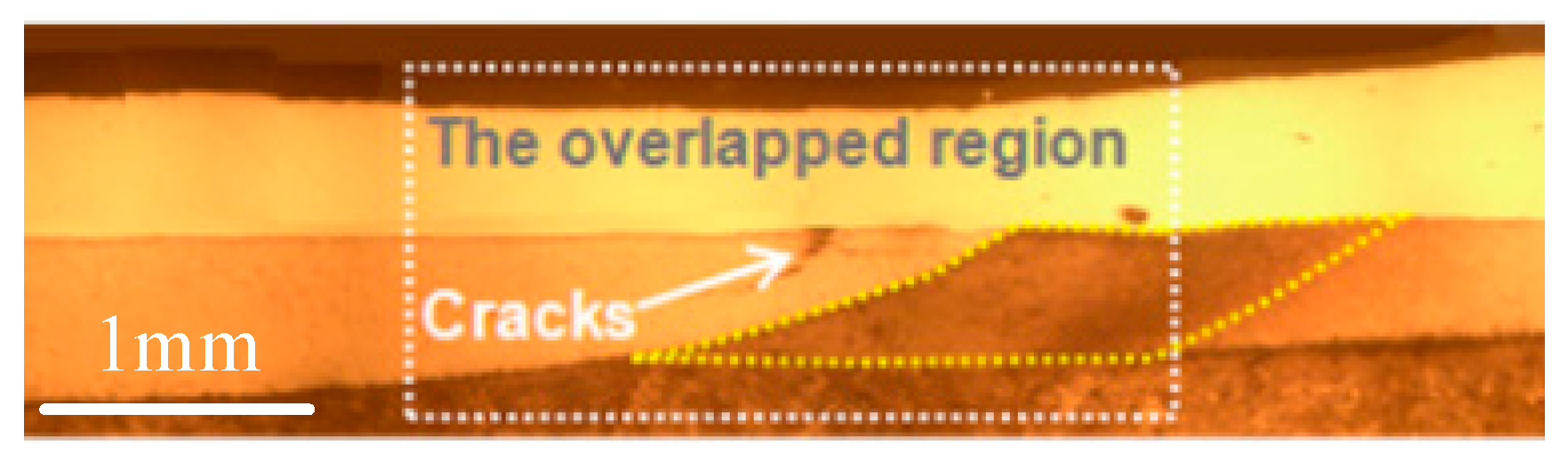
- The clad, HAZ, and the substrate would present diverse crack sensitivity. The fatigue behavior of the cladded material is mainly determined by the properties of the HAZ, whereas the fracture does not stem from this zone.
- (6)
- In order to restrain the martensitic transformation and ultimately enhance the properties of the cladded layer, conducting heat treatment and mixing strengthening element into the cladding material are popular methods to optimize the laser-cladding process.
Author Contributions
Funding
Institutional Review Board Statement
Informed Consent Statement
Data Availability Statement
Conflicts of Interest
References
- Zhong, W.; Hu, J.J.; Shen, P.; Wang, C.Y.; Lius, Q.Y. Experimental investigation between rolling contact fatigue and wear of high-speed and heavy-haul railway and selection of rail material. Wear 2011, 271, 2485–2493. [Google Scholar] [CrossRef]
- Panda, B.; Balasubramaniam, R.; Dwivedi, G. On the corrosion behaviour of novel high carbon rail steels in simulated cyclic wet—Dry salt fog conditions. Corros. Sci. 2008, 50, 1684–1692. [Google Scholar] [CrossRef]
- Lai, Q.; Abrahams, R.; Yan, W.; Qiu, C.; Mutton, P.; Paradowska, A.; Soodi, M.; Wu, X. Influences of depositing materials, processing parameters and heating conditions on material characteristics of laser-cladded hypereutectoid rails. J. Mater. Process. Technol. 2019, 263, 1–20. [Google Scholar] [CrossRef]
- Hu, Y.; Zhou, L.; Ding, H.H.; Tan, G.X.; Lewis, R.; Liu, Q.Y.; Guo, J.; Wang, W.J. Investigation on wear and rolling contact fatigue of wheel-rail materials under various wheel/rail hardness ratio and creepage conditions. Tribol. Int. 2020, 143, 106091. [Google Scholar] [CrossRef]
- Biazon, L.; Ferrer, B.P.; Toro, A.; Cousseau, T. Correlations between rail grease formulation and friction, wear and RCF of a wheel/rail tribological pair. Tribol. Int. 2021, 153, 106566. [Google Scholar] [CrossRef]
- Lewis, R.; Olofsson, U. Wheel-Rail Interface Handbook; Woodhead Publishing: Sawston, UK, 2009. [Google Scholar] [CrossRef]
- Lu, P.; Lewis, S.R.; Fretwell-Smith, S.; Engelberg, D.L.; Fletcher, D.I.; Lewis, R. Laser cladding of rail; the effects of depositing material on lower rail grades. Wear 2019, 438–439. [Google Scholar] [CrossRef]
- Kabo, E.; Ekberg, A.; Maglio, M. Rolling contact fatigue assessment of repair rail welds. Wear 2019, 436–437, 203030. [Google Scholar] [CrossRef]
- Frick, A. Rail grinding operations in Sweden. In European Railway Review; Russel Publishing Limited: Westerham, UK, 2007. [Google Scholar]
- Zhong, W.; Ren, J.; Wang, W.; Liu, Q.; Zhou, Z. Investigation between rolling contact fatigue and wear of high speed and heavy haul railway. Tribol. Mater. Surf. Interfaces 2010, 4, 197–202. [Google Scholar] [CrossRef]
- Sichani, M.S.; Bezin, Y. Differential wear modelling—Effect of weld-induced material inhomogeneity on rail surface quality. Wear 2018, 406–407, 43–52. [Google Scholar] [CrossRef]
- Zhang, D.; Xu, P.; Zhai, W.; Zhang, X. Long-term evolution mechanism of the rail weld irregularity in metro lines based on the wear theory. Wear 2020, 444–445, 203160. [Google Scholar] [CrossRef]
- Shi, H.C.; Shi, L.B.; Ding, H.H.; Wang, W.J.; Jiang, W.J.; Guo, J.; Liu, Q.Y. Influence of laser strengthening techniques on anti-wear and anti-fatigue properties of rail welding joint. Eng. Fail. Anal. 2019, 101, 72–85. [Google Scholar] [CrossRef]
- Liu, Z.; Wang, X.; Kim, H.; Zhou, Y.; Cong, W.; Zhang, H. Investigations of Energy Density Effects on Forming Accuracy and Mechanical Properties of Inconel 718 Fabricated by LENS Process. Procedia Manuf. 2018, 26, 731–739. [Google Scholar] [CrossRef]
- Wang, X.; Deng, D.; Zhang, H. Effects of mass energy and line mass on characteristics of the direct laser fabrication parts. Rapid Prototyp. J. 2018, 24, 240–245. [Google Scholar] [CrossRef]
- Wang, X.; Deng, D.; Hu, Y.; Ning, F.; Wang, H.; Cong, W.; Zhang, H. Overhang structure and accuracy in laser engineered net shaping of Fe-Cr steel. Opt. Laser Technol. 2018, 106, 357–365. [Google Scholar] [CrossRef]
- Roy, T.; Lai, Q.; Abrahams, R.; Mutton, P.; Paradowska, A.; Soodi, M.; Yan, W. Effect of deposition material and heat treatment on wear and rolling contact fatigue of laser cladded rails. Wear 2018, 412–413, 69–81. [Google Scholar] [CrossRef]
- Haibo, Q.I.; Quangai, X.U.; Yanqing, Z.; Tengda, G.; Deliang, R. Study on Realization Method of Automatic Repair Wear Rail by Laser Cladding. J. Mech. Eng. 2017, 53, 160–165. [Google Scholar] [CrossRef]
- Roy, T.; Paradowska, A.; Abrahams, R.; Law, M.; Mutton, P.; Soodi, M.; Yan, W. Residual stress in laser cladded heavy-haul rails investigated by neutron diffraction. J. Mater. Process. Technol. 2020, 278, 116511. [Google Scholar] [CrossRef]
- Roy, T.; Abrahams, R.; Paradowska, A.; Lai, Q.; Mutton, P.; Soodi, M.; Fasihi, P.; Yan, W. Evaluation of the mechanical properties of laser cladded hypereutectoid steel rails. Wear 2019, 432–433, 202930. [Google Scholar] [CrossRef]
- Zhu, Y.; Yang, Y.; Mu, X.; Wang, W.; Yao, Z.; Yang, H. Study on wear and RCF performance of repaired damage railway wheels: Assessing laser cladding to repair local defects on wheels. Wear 2019, 430–431, 126–136. [Google Scholar] [CrossRef]
- Fu, Z.K.; Ding, H.H.; Wang, W.J.; Liu, Q.Y.; Guo, J.; Zhu, M.H. Investigation on microstructure and wear characteristic of laser cladding Fe-based alloy on wheel/rail materials. Wear 2015, 330–331, 592–599. [Google Scholar] [CrossRef]
- Lewis, S.R.; Fretwell-Smith, S.; Goodwin, P.S.; Smith, L.; Lewis, R.; Aslam, M.; Fletcher, D.I.; Murray, K.; Lambert, R. Improving rail wear and RCF performance using laser cladding. Wear 2016, 366–367, 268–278. [Google Scholar] [CrossRef]
- Lewis, S.R.; Lewis, R.; Goodwin, P.S.; Fretwell-Smith, S.; Fletcher, D.I.; Murray, K.; Jaiswal, J. Full-scale testing of laser clad railway track; Case study—Testing for wear, bend fatigue and insulated block joint lipping integrity. Wear 2017, 376–377, 1930–1937. [Google Scholar] [CrossRef]
- Narayanan, A.; Mostafavi, M.; Pirling, T.; Kabra, S.; Lewis, R.; Pavier, M.J.; Peel, M.J. Residual stress in laser cladded rail. Tribol. Int. 2019, 140, 105844. [Google Scholar] [CrossRef]
- Meng, L.; Zhao, W.; Hou, K.; Kou, D.; Yuan, Z.; Zhang, X.; Xu, J.; Hu, Q.; Wang, D.; Zeng, X. A comparison of microstructure and mechanical properties of laser cladding and laser-induction hybrid cladding coatings on full-scale rail. Mater. Sci. Eng. A 2019, 748, 1–15. [Google Scholar] [CrossRef]
- Wang, K.; Chang, B.; Lei, Y.; Fu, H.; Lin, Y. Effect of cobalt on microstructure and wear resistance of Ni-based alloy coating fabricated by laser cladding. Metals 2017, 7, 551. [Google Scholar] [CrossRef] [Green Version]
- Seo, J.-W.; Kim, J.C.; Kwon, S.-J.; Jun, H.-K. Effects of Laser Cladding for Repairing and Improving Wear of Rails. Int. J. Precis. Eng. Manuf. 2019, 20, 1207–1217. [Google Scholar] [CrossRef]
- Clare, A.; Oyelola, O.; Folkes, J.; Farayibi, P. Laser cladding for railway repair and preventative maintenance. J. Laser Appl. 2012, 24, 032004. [Google Scholar] [CrossRef]
- Guo, H.-m.; Wang, Q.; Wang, W.-j.; Guo, J.; Liu, Q.-y.; Zhu, M.-h. Investigation on wear and damage performance of laser cladding Co-based alloy on single wheel or rail material. Wear 2015, 328–329, 329–337. [Google Scholar] [CrossRef]
- Wang, W.J.; Hu, J.; Guo, J.; Liu, Q.Y.; Zhu, M.H. Effect of laser cladding on wear and damage behaviors of heavy-haul wheel/rail materials. Wear 2014, 311, 130–136. [Google Scholar] [CrossRef]
- Aladesanmi, V.I.; Fatoba, O.S.; Akinlabi, E.T. Laser cladded Ti + TiB2 on steel rail microstructural effect. Procedia Manuf. 2019, 33, 709–716. [Google Scholar] [CrossRef]
- Thawari, N.; Gullipalli, C.; Chandak, A.; Gupta, T.V.K. Influence of laser cladding parameters on distortion, thermal history and melt pool behaviour in multi-layer deposition of stellite 6: In-situ measurement. J. Alloy. Compd. 2020, 157894. [Google Scholar] [CrossRef]
- Shamsaei, N.; Yadollahi, A.; Bian, L.; Thompson, S.M. An overview of Direct Laser Deposition for additive manufacturing; Part II: Mechanical behavior, process parameter optimization and control. Addit. Manuf. 2015, 8, 12–35. [Google Scholar] [CrossRef]
- Wang, X.; Liu, Z.; Guo, Z.; Hu, Y. A fundamental investigation on three–dimensional laser material deposition of AISI316L stainless steel. Opt. Laser Technol. 2020, 126, 106107. [Google Scholar] [CrossRef]
- Zhu, G.; Li, D.; Zhang, A.; Pi, G.; Tang, Y. The influence of laser and powder defocusing characteristics on the surface quality in laser direct metal deposition. Opt. Laser Technol. 2012, 44, 349–356. [Google Scholar] [CrossRef]
- Hemmati, I.; Ocelík, V.; De Hosson, J.T.M. The effect of cladding speed on phase constitution and properties of AISI 431 stainless steel laser deposited coatings. Surf. Coat. Technol. 2011, 205, 5235–5239. [Google Scholar] [CrossRef] [Green Version]
- Lee, H.-K. Effects of the cladding parameters on the deposition efficiency in pulsed Nd:YAG laser cladding. J. Mater. Process. Technol. 2008, 202, 321–327. [Google Scholar] [CrossRef]
- Selcuk, C. Laser metal deposition for powder metallurgy parts. Powder Metall. 2011, 54, 94–99. [Google Scholar] [CrossRef]
- Vilar, R. Laser cladding. Laser Appl. 2001, 11, 64–79. [Google Scholar] [CrossRef]
- Zhou, S.; Dai, X.; Zheng, H. Microstructure and wear resistance of Fe-based WC coating by multi-track overlapping laser induction hybrid rapid cladding. Opt. Laser Technol. 2012, 44, 190–197. [Google Scholar] [CrossRef]
- Navas, C.; Cadenas, M.; Cuetos, J.M.; de Damborenea, J. Microstructure and sliding wear behaviour of Tribaloy T-800 coatings deposited by laser cladding. Wear 2006, 260, 838–846. [Google Scholar] [CrossRef]
- Yang, Y.L.; Zhang, D.; Yan, W.; Zheng, Y. Microstructure and wear properties of TiCN/Ti coatings on titanium alloy by laser cladding. Opt. Lasers Eng. 2010, 48, 119–124. [Google Scholar] [CrossRef]
- Lai, Q.; Abrahams, R.; Yan, W.; Qiu, C.; Mutton, P.; Paradowska, A.; Soodi, M. Investigation of a novel functionally graded material for the repair of premium hypereutectoid rails using laser cladding technology. Compos. Part B Eng. 2017, 130, 174–191. [Google Scholar] [CrossRef]
- Clare, A.; Oyelola, O.; Abioye, T.; Farayibi, P. Laser cladding of rail steel with Co–Cr. Surf. Eng. 2013, 29, 731–736. [Google Scholar] [CrossRef]
- Hemmati, I.; Ocelík, V.; De Hosson, J.T.M. Microstructural characterization of AISI 431 martensitic stainless steel laser-deposited coatings. J. Mater. Sci. 2011, 46, 3405–3414. [Google Scholar] [CrossRef] [Green Version]
- Kou, S. Welding Metallurgy, 2nd ed.; John Wiley & Sons, Inc.: Hoboken, NJ, USA, 2003. [Google Scholar]
- Niederhauser, S.; Karlsson, B. Fatigue behaviour of Co–Cr laser cladded steel plates for railway applications. Wear 2005, 258, 1156–1164. [Google Scholar] [CrossRef]
- Jin, Y.; Ishida, M.; Namura, A. Experimental simulation and prediction of wear of wheel flange and rail gauge corner. Wear 2011, 271, 259–267. [Google Scholar] [CrossRef]
- Lewis, S.R.; Lewis, R.; Fletcher, D.I. Assessment of laser cladding as an option for repairing/enhancing rails. Wear 2015, 330–331, 581–591. [Google Scholar] [CrossRef]
- Wang, X.; Deng, D.; Yi, H.; Xu, H.; Yang, S.; Zhang, H. Influences of pulse laser parameters on properties of AISI316L stainless steel thin-walled part by laser material deposition. Opt. Laser Technol. 2017, 92, 5–14. [Google Scholar] [CrossRef]
- Wang, L.; Felicelli, S.D.; Pratt, P. Residual stresses in LENS-deposited AISI 410 stainless steel plates. Mater. Sci. Eng. A 2008, 496, 234–241. [Google Scholar] [CrossRef]
- Jun, H.-K.; Seo, J.-W.; Jeon, I.-S.; Lee, S.-H.; Chang, Y.-S. Fracture and fatigue crack growth analyses on a weld-repaired railway rail. Eng. Fail. Anal. 2016, 59, 478–492. [Google Scholar] [CrossRef]
- Ringsberg, J.W.; Skyttebol, A.; Josefson, B.L. Investigation of the rolling contact fatigue resistance of laser cladded twin-disc specimens: FE simulation of laser cladding, grinding and a twin-disc test. Int. J. Fatigue 2005, 27, 702–714. [Google Scholar] [CrossRef]
- Sadeghi, F.; Jalalahmadi, B.; Slack, T.S.; Raje, N.; Arakere, N.K. A Review of Rolling Contact Fatigue. J. Tribol. 2009, 131. [Google Scholar] [CrossRef]
- Johnson, K.L. Contact Mechanics. J. Tribol. 1985, 108, 464. [Google Scholar]
- Zerbst, U.; Lundén, R.; Edel, K.O.; Smith, R.A. Introduction to the damage tolerance behaviour of railway rails—A review. Eng. Fract. Mech. 2009, 76, 2563–2601. [Google Scholar] [CrossRef] [Green Version]
- Cannon, D.F.; Edel, K.O.; Grassie, S.L.; Sawley, K. Rail defects: An overview. Fatigue Fract. Eng. Mater. Struct. 2003, 26, 865–886. [Google Scholar] [CrossRef]
- Meng, L.; Zeng, X.; Hou, K.; Hu, Q.; Wang, D. Effect of laser cladding and laser-induction hybrid cladding coatings on the bending properties and fracture behavior of rails. Surf. Coat. Technol. 2019, 374, 1038–1050. [Google Scholar] [CrossRef]
- Wang, W.-J.; Fu, Z.-K.; Guo, J.; Zhang, Y.-Q.; Liu, Q.-Y.; Zhu, M.-H. Investigation on wear resistance and fatigue damage of laser cladding coating on wheel and rail materials under the oil lubrication condition. Tribol. Trans. 2016, 59, 810–817. [Google Scholar] [CrossRef]
- Cantini, S.; Cervello, S. The competitive role of wear and RCF: Full scale experimental assessment of artificial and natural defects in railway wheel treads. Wear 2016, 366, 325–337. [Google Scholar] [CrossRef]
- Stock, R.; Pippan, R. RCF and wear in theory and practice—The influence of rail grade on wear and RCF. Wear 2011, 271, 125–133. [Google Scholar] [CrossRef]
- Kapoor, A.; Fletcher, D.I.; Franklin, F.J. The role of wear in enhancing rail life. In Tribology Series; Dowson, D., Priest, M., Dalmaz, G., Lubrecht, A.A., Eds.; Elsevier: Amsterdam, The Neteherlands, 2003; Volume 41, pp. 331–340. [Google Scholar]
- Paladugu, M.; Hyde, R.S. Influence of microstructure on retained austenite and residual stress changes under rolling contact fatigue in mixed lubrication conditions. Wear 2018, 406–407, 84–91. [Google Scholar] [CrossRef]
- Ocelík, V.; de Oliveira, U.; de Boer, M.; de Hosson, J.T.M. Thick Co-based coating on cast iron by side laser cladding: Analysis of processing conditions and coating properties. Surf. Coat. Technol. 2007, 201, 5875–5883. [Google Scholar] [CrossRef] [Green Version]
- de Oliveira, U.; Ocelík, V.; De Hosson, J.T.M. Residual stress analysis in Co-based laser clad layers by laboratory X-rays and synchrotron diffraction techniques. Surf. Coat. Technol. 2006, 201, 533–542. [Google Scholar] [CrossRef] [Green Version]
- Lazić, V.N.; Sedmak, A.S.; Živković, M.M.; Aleksandrović, S.M.; Čukić, R.D.; Jovičić, R.D.; Ivanović, I.B. Theoretical-experimental determining of cooling time (t8/5) in hard facing of steels for forging dies. Therm. Sci. 2010, 14, 235–246. [Google Scholar] [CrossRef]
- Grange, R. Strengthening steel by austenite grain refinement. ASM Trans Quart 1966, 59, 26–48. [Google Scholar]
- Wang, W.J.; Fu, Z.K.; Cao, X.; Guo, J.; Liu, Q.Y.; Zhu, M.H. The role of lanthanum oxide on wear and contact fatigue damage resistance of laser cladding Fe-based alloy coating under oil lubrication condition. Tribol. Int. 2016, 94, 470–478. [Google Scholar] [CrossRef]
- Duarte, V.R.; Rodrigues, T.A.; Schell, N.; Miranda, R.M.; Oliveira, J.P.; Santos, T.G. Hot forging wire and arc additive manufacturing (HF-WAAM). Addit. Manuf. 2020, 35, 101193. [Google Scholar] [CrossRef]
- Donoghue, J.; Antonysamy, A.A.; Martina, F.; Colegrove, P.A.; Williams, S.W.; Prangnell, P.B. The effectiveness of combining rolling deformation with Wire–Arc Additive Manufacture on β-grain refinement and texture modification in Ti–6Al–4V. Mater. Charact. 2016, 114, 103–114. [Google Scholar] [CrossRef]
- Hongxi, L.; Shengwei, J.; Yehua, J.; Xiao-Wei, Z.; Chuanqi, W. Microstructure and Property of Fe60 Composite Coatings by Rotating Magnetic Field Auxiliary Laser Cladding. Chin. J. Lasers 2013, 40, 0103007. [Google Scholar] [CrossRef]
- Hu, Y.; Wang, L.; Yao, J.; Xia, H.; Li, J.; Liu, R. Effects of electromagnetic compound field on the escape behavior of pores in molten pool during laser cladding. Surf. Coat. Technol. 2020, 383, 125198. [Google Scholar] [CrossRef]
- Zhang, N.; Liu, W.; Deng, D.; Tang, Z.; Liu, X.; Yan, Z.; Zhang, H. Effect of electric-magnetic compound field on the pore distribution in laser cladding process. Opt. Laser Technol. 2018, 108, 247–254. [Google Scholar] [CrossRef]
- Chen, L.; Yang, Y.; Jiang, F.; Li, C. Experimental investigation and FEM analysis of laser cladding assisted by coupled field of electric and magnetic. Mater. Res. Express 2018, 6, 016516. [Google Scholar] [CrossRef]


| Substrate | Powder | Process Parameters | Ref. | |||
|---|---|---|---|---|---|---|
| Laser Powder (W) | Scanning Speed (mm/s) | Powder Feed Rate (g/min) | ||||
| Hyper-eutectoid rail CL60 (GB) wheel U71Mn (GB) rail R400HT (EN) HE400 (EN) R260 (EN) R200 (EN) | Fe-based | 316 L, 410 L 410, 420, 421 | 3200 | 16.7–20 | 3RPM | [3,17,18,19,20,21] |
| 500 | 10/8 | 1.2 | ||||
| MSS | [7,22,23,24] | |||||
| TWIP steel | [23] | |||||
| Ni-based | NiCrBSi, Inconel 625, Hastelloy C, Nickel alloy | 1200–1800 | 6.67–15 | 15–30 | [22,25,26,27,28] | |
| 4500 | 16.7 | 18 | ||||
| Co-based | Stellite 6 Stellite 21 | 1600 | 6.67–13.33 | 15–30 | [3,17,22,23,29,30,31] | |
| 1200–1800 | 6.67–15 | 15–30 | ||||
| Other | Ti, TiB2 | 1500 | 16.7 | 2 | [32] | |
| Cladding Material | Sampling Position | Yield Strength (MPa) | UTS (MPa) | Elongation (%) |
|---|---|---|---|---|
| 401 L | Cladding layer | 910 ± 4.1 | 1149 ± 12.5 | 3 ± 0.2 |
| HAZ | 1060 ± 8.1 | 1317 ± 6.2 | 4.32 ± 0.02 | |
| Substrate | 1000 ± 8.1 | 1299 ± 4.7 | 5.8 ± 0.04 | |
| SS420 | Cladding layer | 800 ± 10.3 | 1455 ± 19.4 | 1.4 ± 0.3 |
| HAZ | 910 ± 5 | 1156 ± 3 | 10.2 ± 0.05 | |
| Substrate | 880 ± 0 | 1240 ± 10 | 8.8 ± 0.1 | |
| Stellite 6 | Cladding layer | 925 ± 4.7 | 1302 ± 47.6 | 2.2 ± 0.2 |
| HAZ | 855 ± 15 | 1092 ± 4 | 10.2 ± 0.1 | |
| Substrate | 910 ± 12.5 | 1262 ± 2.5 | 7.8 ± 0 | |
| Non-cladded rail steel | 917 ± 13.88 | 1288 ± 6.24 | 8.27 ± 0.22 |
Publisher’s Note: MDPI stays neutral with regard to jurisdictional claims in published maps and institutional affiliations. |
© 2021 by the authors. Licensee MDPI, Basel, Switzerland. This article is an open access article distributed under the terms and conditions of the Creative Commons Attribution (CC BY) license (http://creativecommons.org/licenses/by/4.0/).
Share and Cite
Wang, X.; Lei, L.; Yu, H. A Review on Microstructural Features and Mechanical Properties of Wheels/Rails Cladded by Laser Cladding. Micromachines 2021, 12, 152. https://doi.org/10.3390/mi12020152
Wang X, Lei L, Yu H. A Review on Microstructural Features and Mechanical Properties of Wheels/Rails Cladded by Laser Cladding. Micromachines. 2021; 12(2):152. https://doi.org/10.3390/mi12020152
Chicago/Turabian StyleWang, Xinlin, Lei Lei, and Han Yu. 2021. "A Review on Microstructural Features and Mechanical Properties of Wheels/Rails Cladded by Laser Cladding" Micromachines 12, no. 2: 152. https://doi.org/10.3390/mi12020152