The Micro Topology and Statistical Analysis of the Forces of Walking and Failure of an ITAP in a Femur
Abstract
:1. Introduction
2. Experimental Methodology
2.1. The Initial Design, Boundary Conditions and Mesh
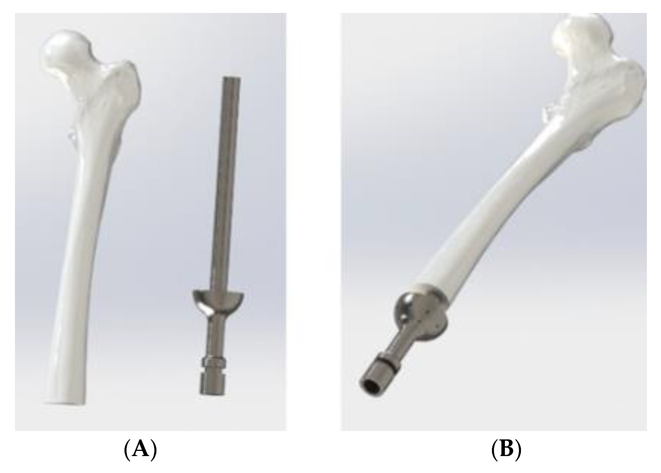
- The ITAP and femur are both cylindrical, where the femur has an outer diameter of 28 mm and is extruded for 311.5 mm. Whilst there is often a curve in the femur, the tensor faciae latae muscle can reduce the stress acting along the bone and therefore reduce any pronounced stress concentrations acting along the femur [18].
- At one end of the femur there is a 14 mm diameter hole, centred in the middle, cut to a depth of 160 mm.
- The material properties of the femur have been assumed to be cortical bone, which has a σs of 110 and 120 MPa for compressional and tensional forces. The mechanical strength of a femur depends on numerous factors, such as age, porosity and mineral content. However, Marco et al. [19] and Reilly and Burstein [20] found average elastic and shear moduli of human femur specimens which can be used as a preliminary step towards modelling the bone housing ITAP implant. A summary of these mechanical properties is presented by Bird et al. [13].
- The material used for the ITAP has been set as Ti from the ANSYS’s database, this has a σs of 930 MPa and an ultimate tensile stress, UTS, of 1070 MPa. The material selection for the computational modelling is in line with the Ti material used for the ITAP, thus the modelling is a comparable study.
- As the focus of the simulation is on the ITAP, the femur is fixed in place to the pelvis.
- The femur will not be simulated and the free body diagram (FBD) will only consist of the ITAP and the resulting σ is analysed for the impact on the bone anchor.
- σMax across the entire geometry
- σMax recorded in the core of the ITAP using a set pathway in the centre of the cylinder
- σMax recorded in the core of Section B only using a pathway control.
- A face sizing on both ends of each section of the ITAP, measured at 2 mm.
- A face sizing on the cylindrical surface of each section of the ITAP, measured at 2 mm.
- An edge sizing on both edges of the ITAP sections, divided by 25.
2.2. Simulated Results of the ITAP Standard Design
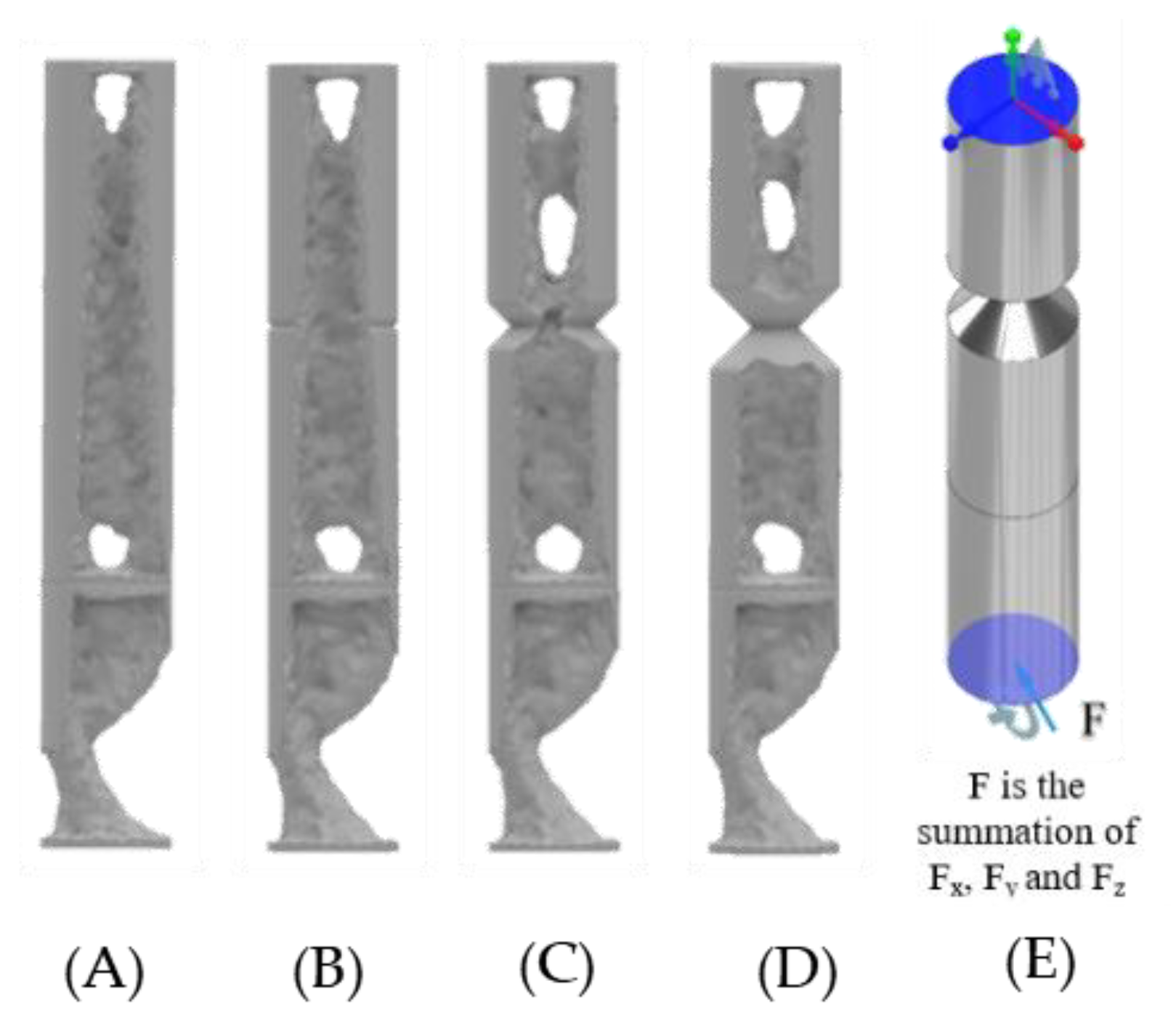
- The basic ITAP design has regions of σ above 930 MPa, with a σmax of 1175.6 MPa at the A-B joint interface. This is greater than the σs of the Ti, and could result in a section of the ITAP permanently deforming and making it unsuitable for use.
- For all simulated geometries the section A σ is greater than both the compressive (110 MPa) and tensile (120 MPa) strength. This only occurs at the very start of the embedded part of the ITAP.
3. Topology Optimisation of for the ITAP Model
3.1. ANSYS Model
- The connecting surfaces of the ITAP and bone.
- The connection of the top surface of the ITAP and bone.
- The top of Section C joined to Section B of the ITAP (Figure 8B).
3.2. 2D Simulations Using MATLAB Functions
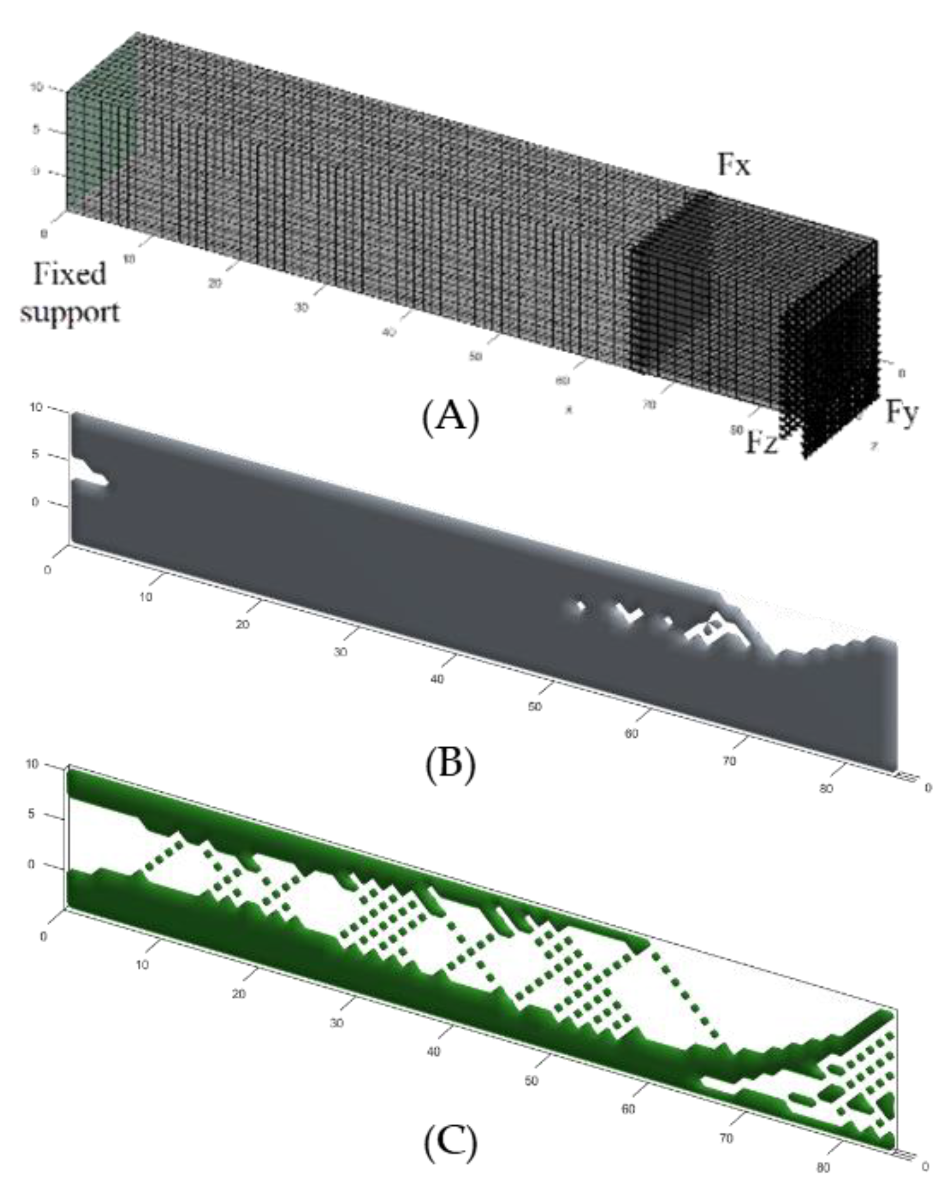
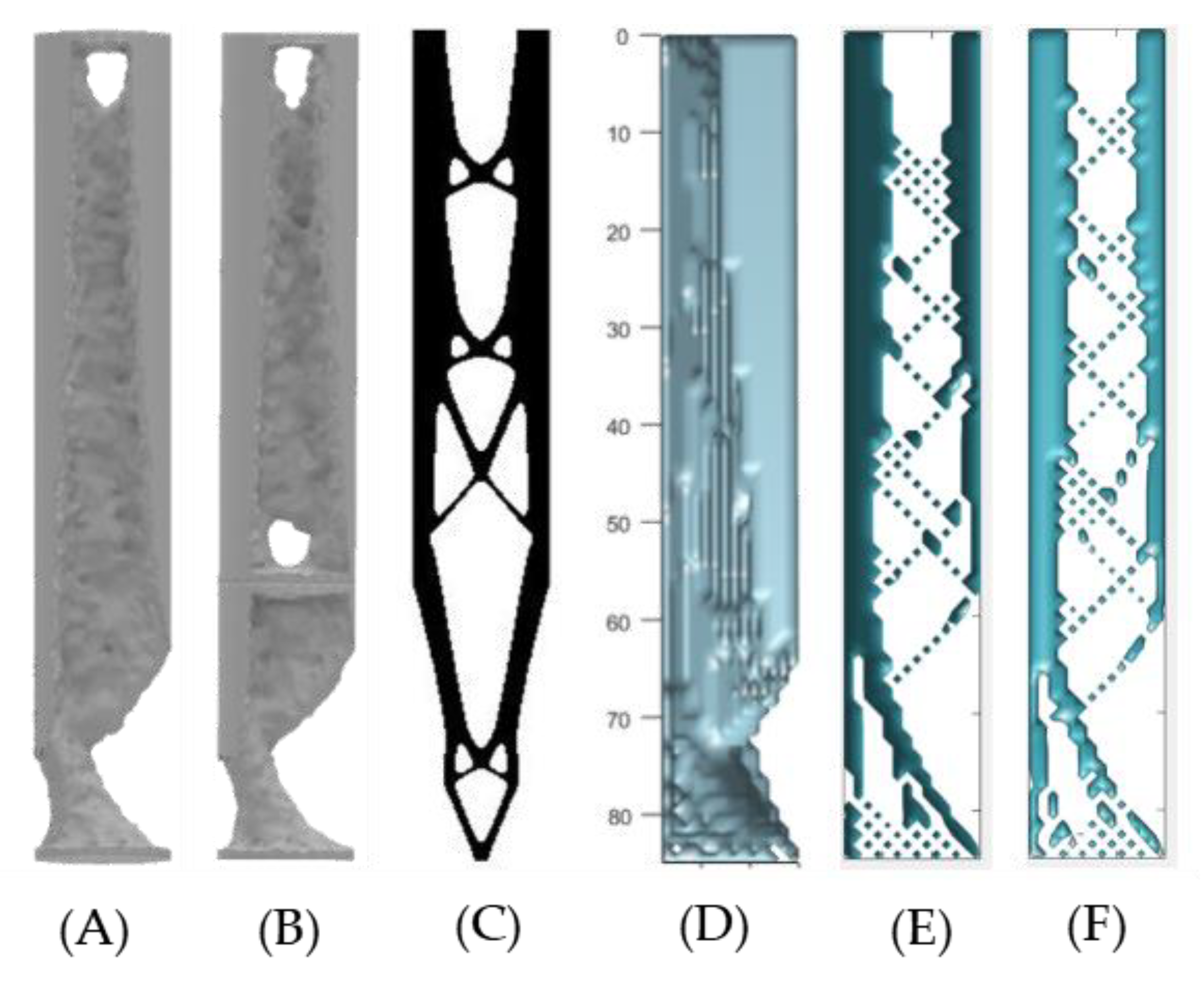
- Function control levelset88 (Nelx, Nely, Vmax, Tau) are used
- The simulation considers the cross-section of the ITAP, external sections away from the bone and fusing muscle.
- The length X and Y are the length and diameter of the external region of the ITAP, Sections C and D, (represented by Nelx and Nely, respectively).
- The position of the applied load, interconnectivity and complexity is denoted by Tau and represents the regularization parameters which are set to the recommended value of 2 × 10⁻⁴ [21].
- The magnitude of the forces is not considered.
- The Young’s modulus for the material is set to 1, whereas the Young’s modulus of the voids has been set to 0.
- Poisson’s Ratio is set at 0.3.
3.3. 3D Simulations Using MATLAB Functions
- The dimensions of the geometry are individual to each simulated model; this consists of Nelx, Nely and Nelz.
- Volfrac represents the volume fraction limit of the simulations; the range used for this study will be concordant with the 2D MATLAB study ranging between 50% and 95% in intervals of 5%.
- Penal represents penalization procedure and is usually referred to as the Solid Isotropic Material with Penalization (SIMP), which is used as a binary solver where penal > 1. In this study it is being set as a constant of 1 following the recommendations of the author.
- Rmin is the filter size which is the distance between the centroid of element i and element j of the model, this has been set to a value of 1, so there is a millimetre between the centre of each element.
- The Young’s modulus of the material has been set to 1 while the Young’s modulus of the voids has been set to the value of 0.
- Poisson’s ratio is set to 0.3.
- The fixed supports are distributed evenly over the following coordinate positions fixed in all three axes:
- ○
- Standard: X1 = 0, X2 = 0, Y1 = 0, Y2 = 14, Z1 = 0, Z2 = 14.
- ○
- Vertical: X1 = 0, X2 = 0, Y1 = 0, Y2 = 14, Z1 = 0, Z2 = 1.
- ○
- Horizontal: X1 = 0, X2 = 0, Y1 = 0, Y2 = 1, Z1 = 0, Z2 = 14.
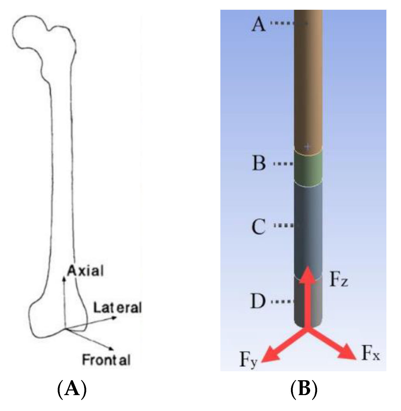
- The applied forces are Axial 3168.63 N, Lateral −833.85 N and Frontal 958.93 N in the following axes Fx, Fy, Fz, respectively.
- The following coordinates and forces have been used in the load distribution:
- ○
- Standard: Fx, Fy and Fz at X1 = 85, X2 = 85, Y1 = 0, Y2 = 14, Z1 = 0, Z2 = 14.
- ○
- Vertical: Fx and Fy at X1 = 85, X2 = 85, Y1 = 0, Y2 = 14, Z1 = 0, Z2 = 1.
- ○
- Horizontal: Fx and Fz at X1 = 85, X2 = 85, Y1 = 0, Y2 = 1, Z1 = 0, Z2 = 14.
4. Topology of the ITAP Design under Extreme Loads
4.1. ANSYS Topology of the ITAP with Extreme Loads Applied
4.2. 3D MATLAB Analysis of the ITAP with Extreme Loads Applied
5. Discussion
5.1. Similarities of the ANSYS, 2D and 3D MATLAB Topology Studies on the ITAP for Walking Simulations
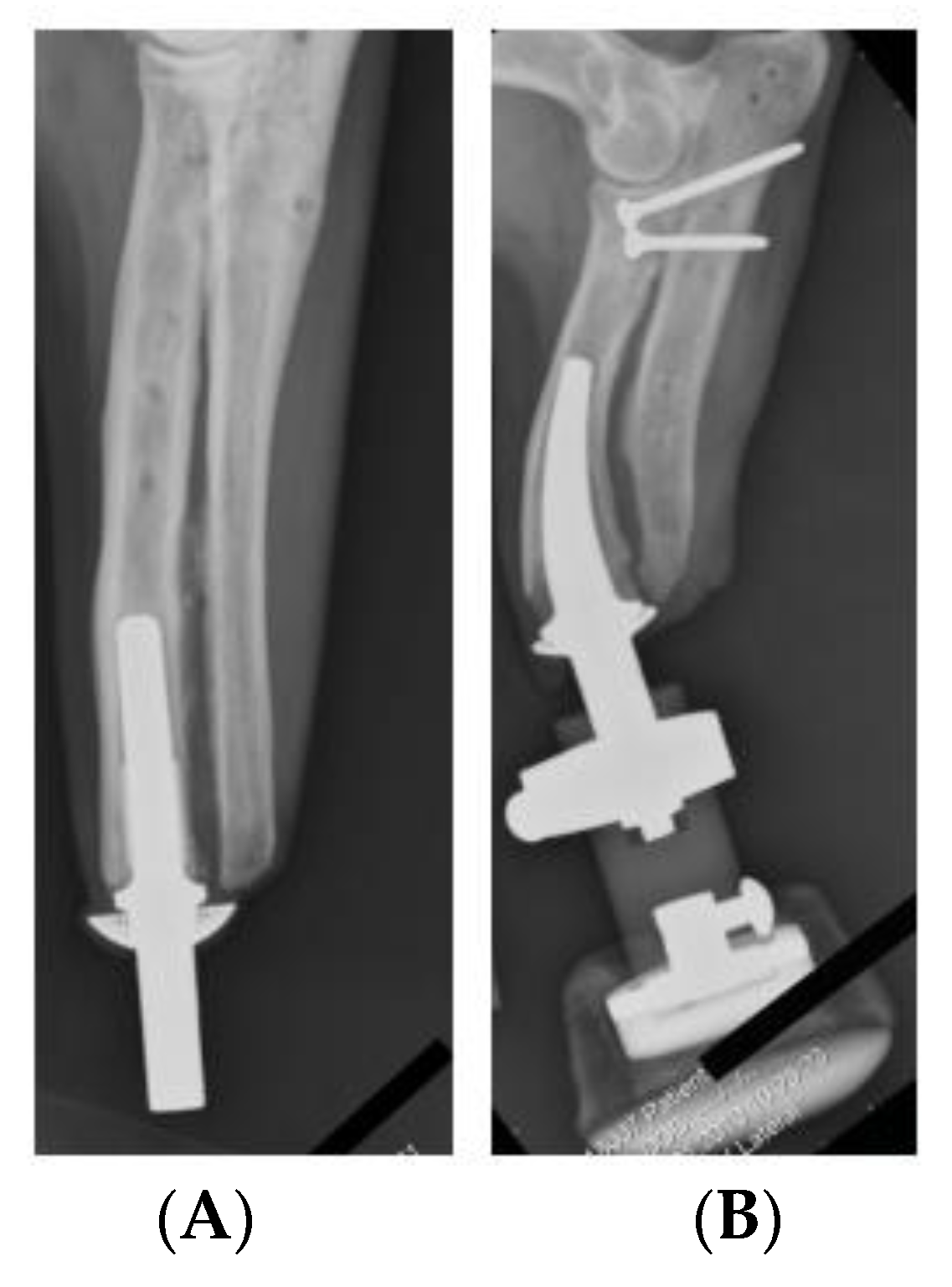
- Integrate a stress raiser on the ITAP at the end of Section B at the bone anchor, with appropriate fillets on either side to increase contact with bone and reduce residual σ under load at the connection between the ITAP and anchor.
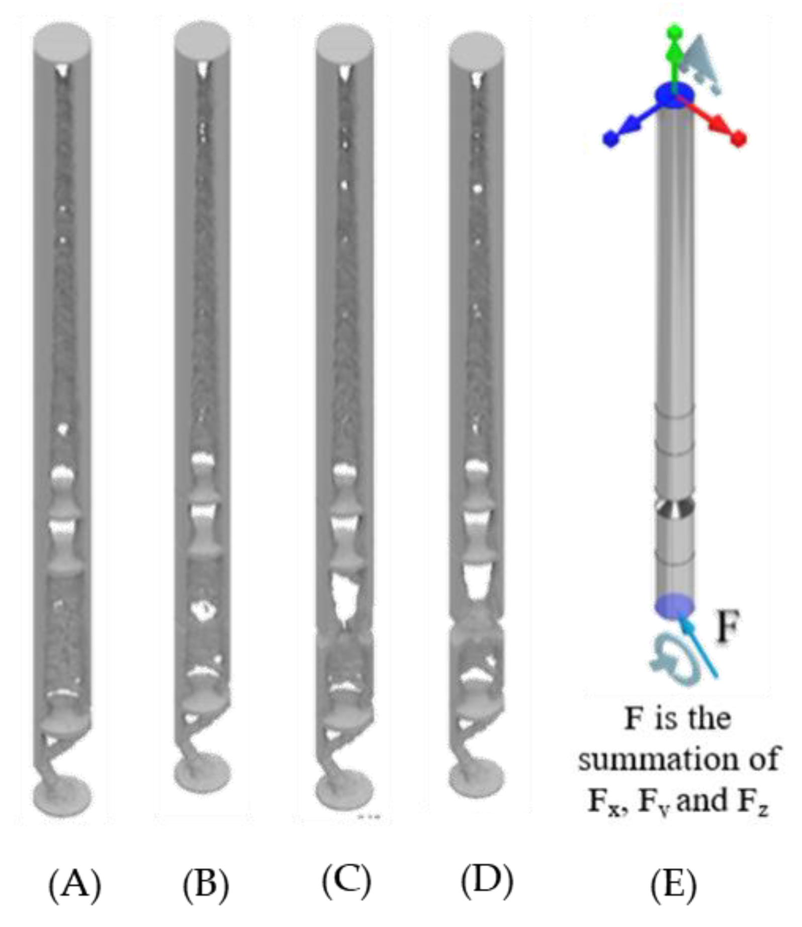
- The external walls around the ITAP are key to the stability of the design; minimal removal in any direction will weaken the model. However, removing critical material from the combined direction of the Lateral and Frontal forces will introduce a significant weakness in design. Removal of material in the opposite direction will also have a significant reduction in strength.
- The internal topology of the ITAP should be designed following the results of the study’s triangular-based patterns for stability, with AM production processes in mind.
- Any design models should be simulated using the forces utilised in these studies as well as simulation with forces that would fracture the femur.
5.2. Discussion and Similarities of the ANSYS and 3D MATLAB Topology Studies on the ITAP when Exposed to Extreme Loads
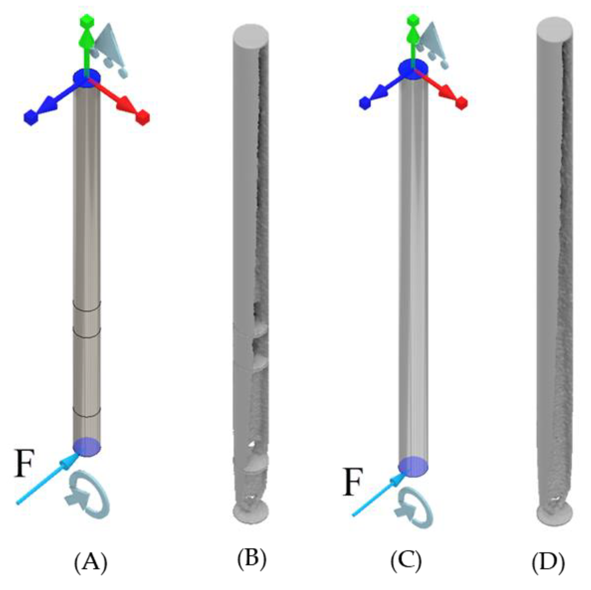
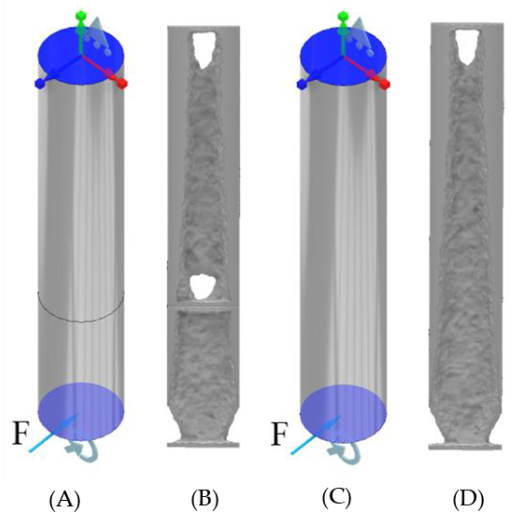
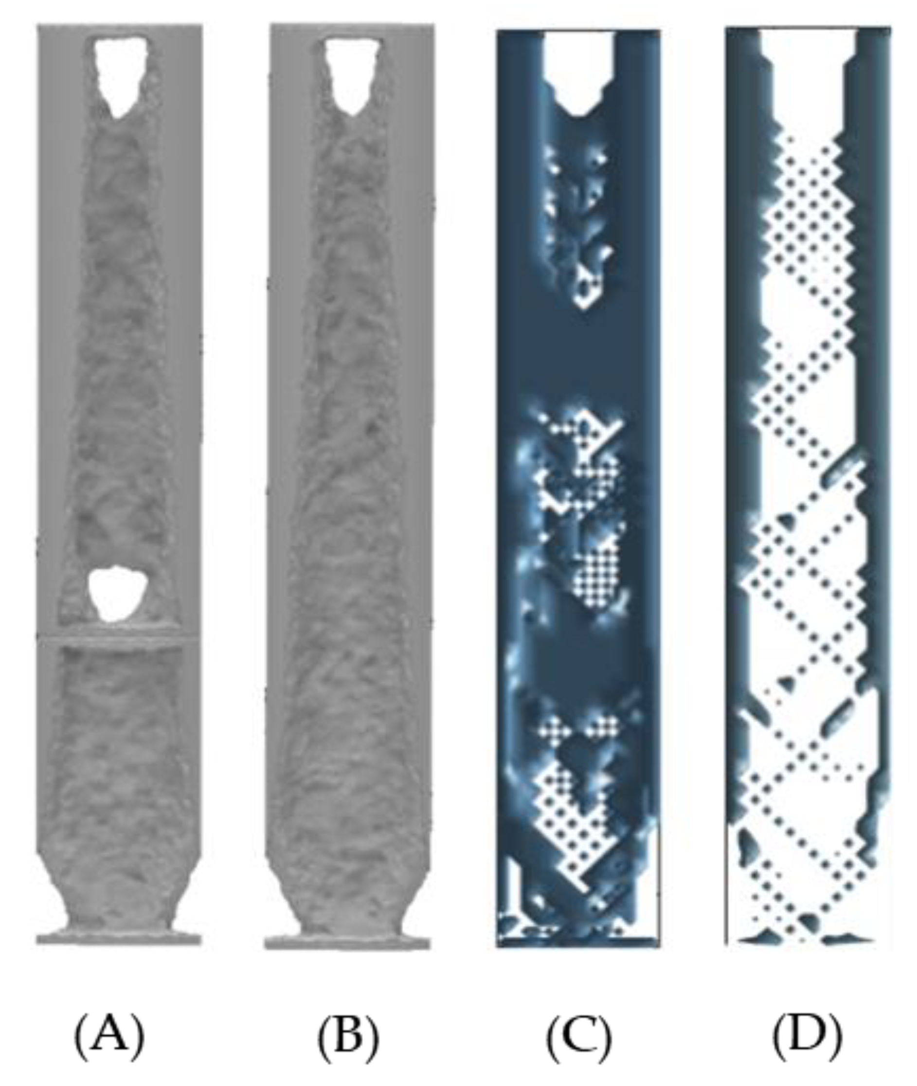
- The σ within the ITAP is significantly greater than the capacity of the anchor. Therefore, design iterations are needed to remove the failure of bone, and the location of the σMax is the same as the walking simulations in the anchor.
- The external walls, perpendicular to the forces are critical to the structural integrity of the ITAP. This is more prominent in the wall to which the shear force is directed.
6. Conclusions and Recommendations for Future Work
- Due to advances in medical practises, CT scanning has been performed identifying the condition and strength of the bone anchor. Thus, allowing for clear understanding of how an ITAP will integrate within the user after an amputated femur. The acting loads applied to the ITAP when in use, have been ascertained, allowing for design and manufacture using AM methods to incorporating topology modifications bespoke to the users’ lifestyle.
- The topology studies of the ITAP have been performed using ANSYS and 2D and 3D MATLAB models. The use of the 2D modelling has quick results that allows for rapid modelling, with alternative length of prosthetics. However, there is no control on the magnitude of the applied load. As such it is only recommend for quick analysis for an idea of where material is critical with in a cross section. The use of the 3D code is better suited to live modelling as there is more control on both the material properties and applied loads. The benefit of this is a visual guide to the critical material that is accurate to the model. However, the problem is the simulation does not yield numerical results and have limited geometry modelling. As such it is best suited for quick accurate visual modelling of cross-sections. In total 10 2D and 60 3D Matlab simulations where carried out within this research, all results yield from these simulations gave clear insight into the topology of the ITAP under load.
- ANSYS code has been developed for advances topology modelling. This has allowed for in-depth studies into the ITAPs geometry looking at the core material and σ that are being applied to the ITAP. This has allowed for in-depth review of the ITAPs critical material and local maximum stresses when modelling the applied loads. The downside of this simulation is that it is computationally expensive and time consuming, a large proportion of time was utilised simulation the 24 different ANSYS topology models.
- The topology studies for both the walking and extreme loads have identified critical areas of material within the ITAP that are needed for σ to dissipate through the product. Through the use of ANSYS, 2D and 3D MATLAB models, it can be concluded that when the ITAP is exposed to walking loads, the critical material is solely located in line with the summation of the walking loads, which is set in a fixed direction. It is also critical that the section of the ITAP that meets the bone anchor does not exceed the bone σs of 110 MPa as this will cause further injury to the user.
- The critical support material identified from the topology studies is directly in line with the extreme loads. However, in use as an extreme load can be applied from any direction, and all of the ITAP geometry can be assumed as critical so a controlled failure safety notch feature is adopted. As such it can be stated that a developed ITAP must not exceed the σs of bone but also be capable of withstanding loads for daily use like walking. For the failsafe to work the σ within the core section C must exceed the material UTS when exposed to extreme loads in any direction.
Author Contributions
Funding
Acknowledgments
Conflicts of Interest
References
- Charles, Q. Brute Force: Humans Can Sure Take a Punch. LIVESCIENCE. 3 February 2019. Available online: https://www.livescience.com/6040-brute-force-humans-punch.html (accessed on 3 August 2019).
- Teitel, A.S. How Much Force Does It Take to Break A Bone? Seeker. 20 October 2016. Available online: https://www.seeker.com/how-much-force-does-it-take-to-break-a-bone-2056139307.html (accessed on 3 August 2019).
- Mckay, B. Development of Lower Extremity Injury Criteria and Biomechanical Surrogate to Evaluate Military Vehicle Occupant Injury during an Explosive Blast Event. Bachelor’s Dissertation, Wayne State University, Detroit, MI, USA, 2010; pp. 1–146. [Google Scholar]
- Langford, E.; Griffiths, C.A. The mechanical strength of additive manufactured intraosseous transcutaneous amputation prosthesis, known as the ITAP. AIMS Bioeng. 2018, 5, 133–150. [Google Scholar] [CrossRef]
- Zhang, M.; Turner-Smith, A.R.; Roberts, V.C.; Tanner, A. Frictional action at lower limb/prosthetic socket interface. Med. Eng. Phys. 1996, 18, 207–214. [Google Scholar] [CrossRef]
- Pendegrass, C.J.; Goodship, A.E.; Price, J.S.; Blunn, G.W. Nature’s Answer to Breaching the Skin Barrier: An Innovative Development for Amputees; The Centre for Biomedical Engineering, Institute of Orthopaedics and Musculoskeletal Science: Stanmore, UK, 2006; pp. 56–67. [Google Scholar] [CrossRef]
- Niinomi, M. Mechanical properties of biomedical titanium alloys. Mater. Sci. Eng. A 1998, 243, 231–236. [Google Scholar] [CrossRef]
- Handbook of Materials for Medical Devices. Overview of Biomaterials and Their Use in Medical Devices. Available online: https://www.asminternational.org/documents/10192/1849770/06974G_Chapter_1.pdf (accessed on 4 July 2019).
- Asri, R.I.M.; Harun, W.S.W.; Samykano, M.; Lah, N.A.C.; Ghani, S.A.C.; Tarlochan, F.; Raza, M.R. Corrosion and surface mod-ification on biocompatible metals: A review. Mater. Sci. Eng. 2017, 1261–1274. [Google Scholar] [CrossRef] [PubMed] [Green Version]
- Deng, L.; Deng, Y.; Xie, K. AgNPs-decorated 3D printed PEEK implant for infection control and bone repair. Colloids Surf. B Biointerfaces 2017, 483–492. [Google Scholar] [CrossRef] [PubMed]
- Kang, N.V.; Morritt, D.; Pendegrass, C.; Blunn, G. Use of ITAP implants for prosthetic reconstruction of extra-oral craniofacial defects. J. Plast. Reconstr. Aesthetic Surg. 2012, 66, 497–505. [Google Scholar] [CrossRef] [PubMed]
- Newcombe, L.; Dewar, M.; Blunn, G.; Fromme, P. Effect of amputation level on the stress transferred to the femur by an artificial limb directly attached to the bone. Med. Eng. Phys. 2013, 35, 1744–1753. [Google Scholar] [CrossRef] [PubMed]
- Bird, J.; Langford, E.; Griffiths, C. A study into the fracture control of 3D printed intraosseous transcutaneous amputation prostheses, known as ITAPs. AIMS Environ. Sci. 2020, 7, 29–42. [Google Scholar] [CrossRef]
- Nebergall, A.; Bragdon, C.; Antonellis, A.; Kärrholm, J.; Brånemark, R.; Malchau, H. Stable fixation of an osseointegated implant system for above-the-knee amputees. Acta Orthop. 2012, 83, 121–128. [Google Scholar] [CrossRef] [PubMed]
- Fitzpatrick, N.; Smith, T.J.; Pendegrass, C.J.; Yeadon, R.; Ring, M.; Goodship, A.E.; Blunn, G.W. Intraosseous Transcutaneous Amputation Prosthesis (ITAP) for Limb Salvage in 4 Dogs. Veter. Surg. 2011, 40, 909–925. [Google Scholar] [CrossRef] [PubMed]
- Sullivan, J.; Uden, M.; Robinson, K.P.; Sooriakumaran, S.; Robinson, P.K.P. Rehabilitation of the transfemoral amputee with an osseointegrated prosthesis. Prosthet. Orthot. Int. 2003, 27, 114–120. [Google Scholar] [CrossRef] [PubMed]
- Mahmoudi, M. Femur Bone. Grabcad Community. Available online: https://grabcad.com/library/femur-bone-2 (accessed on 5 July 2019).
- Rybicki, E.F.; Simonen, F.A.; Weis, E.B., Jr. On the mathematical analysis of stress in the human femur. J. Biomech. 1972, 5, 203–215. [Google Scholar] [CrossRef]
- Marco, M.; Giner, E.; Larraínzar-Garijo, R.; Caeiro, J.R.; Miguélez, M.H. Numerical modelling of femur fracture and experimental validation using bone simulant. Ann. Biomed. Eng. 2017, 45, 2395–2408. [Google Scholar] [CrossRef] [PubMed]
- Reilly, D.T.; Burstein, A.H. The elastic and ultimate properties of compact bone tissue. J. Biomech. 1975, 8, 393–405. [Google Scholar] [CrossRef]
- Duda, G.N.; Schneider, E.; Chao, E.Y. Internal forces and moments in the femur during walking. J. Biomech. 1997, 30, 933–941. [Google Scholar] [CrossRef]
- Otomori, M.; Yamada, T.; Izui, K.; Nishiwaki, S. Matlab code for a level set-based topology optimization method using a reaction diffusion equation. Struct. Multidiscip. Optim. 2015, 51, 1159–1172. [Google Scholar] [CrossRef] [Green Version]
- Liu, K.; Tovar, A. An efficient 3D topology optimization code written in Matlab. Struct. Multidiscip. Optim. 2014, 50, 1175–1196. [Google Scholar] [CrossRef] [Green Version]
- Wu, J.; Aage, N.; Westermann, R.; Sigmund, O. Infill Optimization for Additive Manufacturing—Approaching Bone-Like Porous Structures. IEEE Trans. Vis. Comput. Graph. 2018, 24, 1127–1140. [Google Scholar] [CrossRef] [PubMed] [Green Version]




| ITAP Designs | Standard | 13 mm Safety Notch | 9 mm Safety Notch | 5 mm Safety Notch |
|---|---|---|---|---|
| σMax [MPa] In the model | 1175.6 | 939.5 | 939.5 | 3313.8 |
| σMax [MPa] Core of the ITAP | 79.5 | 74.5 | 146.1 | 1003.6 |
| Vertical height from applied loads, z domain [mm] | 104.5 | 104.5 | 55.1 | 55.0 |
| σMax [MPa] in Section A | 570.3 | 735.6 | 735.6 | 735.6 |
| σMax [MPa] Core of Section A | 67.1 | 72.1 | 72.1 | 72.1 |
| Vertical height from applied loads, z domain [mm] | 107.4 | 107.4 | 107.4 | 107.4 |
| σMax [MPa] in Section C | 422.6 | 474.5 | 861.6 | 3313.8 |
| σMax [MPa] Core of Section C | 29.5 | 30.8 | 150.3 | 895.4 |
| Vertical height from applied loads, z domain [mm] | 64.7 | 49.9 | 53.3 | 59.0 |
| σMax and Mass Reduction | Walking Loads | Extrema Load | |||
|---|---|---|---|---|---|
| ITAP Designs | Standard | 13 mm Safety Notch | 9 mm Safety Notch | 5 mm Safety Notch | Standard |
| σMax [MPa] In the model | 1175.6 | 939.5 | 939.5 | 3313.8 | 3220.9 |
| σMax [MPa] Core of the ITAP | 79.5 | 74.5 | 146.1 | 1003.6 | 211.7 |
| Vertical height from applied loads, z domain [mm] | 104.5 | 104.5 | 55.1 | 55.0 | 104.5 |
| σMax [MPa] in Section A | 570.3 | 735.6 | 735.6 | 735.6 | 1813.7 |
| σMax [MPa] Core of Section A | 67.1 | 72.1 | 72.1 | 72.1 | 215.0 |
| Vertical height from applied loads, z domain [mm] | 107.4 | 107.4 | 107.4 | 107.4 | 107.4 |
| σMax [MPa] in Section C | 422.6 | 474.5 | 861.6 | 3313.8 | 1264.0 |
| σMax [MPa] Core of Section C | 29.5 | 30.8 | 150.3 | 895.4 | 64.8 |
| Vertical height from applied loads, z domain [mm] | 64.7 | 49.9 | 53.3 | 59.0 | 69.2 |
| Mass of full ITAP [g] | 187.8 | 187.7 | 186.7 | 184.5 | 187.8 |
| Mass of full ITAP after 50% topology reduction [g] | 93.91 | 93.8 | 93.3 | 92.2 | 93.9 |
| Mass of Section C & D of ITAP [g] | 60.5 | 60.4 | 59.4 | 57.2 | 60.5 |
| Mass of Section C & D of ITAP after 50% topology reduction [g] | 30.2 | 30.2 | 29.7 | 28.6 | 30.2 |
Publisher’s Note: MDPI stays neutral with regard to jurisdictional claims in published maps and institutional affiliations. |
© 2021 by the authors. Licensee MDPI, Basel, Switzerland. This article is an open access article distributed under the terms and conditions of the Creative Commons Attribution (CC BY) license (http://creativecommons.org/licenses/by/4.0/).
Share and Cite
Langford, E.; Griffiths, C.A.; Rees, A.; Bird, J. The Micro Topology and Statistical Analysis of the Forces of Walking and Failure of an ITAP in a Femur. Micromachines 2021, 12, 298. https://doi.org/10.3390/mi12030298
Langford E, Griffiths CA, Rees A, Bird J. The Micro Topology and Statistical Analysis of the Forces of Walking and Failure of an ITAP in a Femur. Micromachines. 2021; 12(3):298. https://doi.org/10.3390/mi12030298
Chicago/Turabian StyleLangford, Euan, Christian Andrew Griffiths, Andrew Rees, and Josh Bird. 2021. "The Micro Topology and Statistical Analysis of the Forces of Walking and Failure of an ITAP in a Femur" Micromachines 12, no. 3: 298. https://doi.org/10.3390/mi12030298
APA StyleLangford, E., Griffiths, C. A., Rees, A., & Bird, J. (2021). The Micro Topology and Statistical Analysis of the Forces of Walking and Failure of an ITAP in a Femur. Micromachines, 12(3), 298. https://doi.org/10.3390/mi12030298


