
Study on Microstructure and Properties of Ni60A/WC Composite Coating by Alternating-Magnetic-Field-Assisted Laser Cladding


Abstract
:1. Introduction
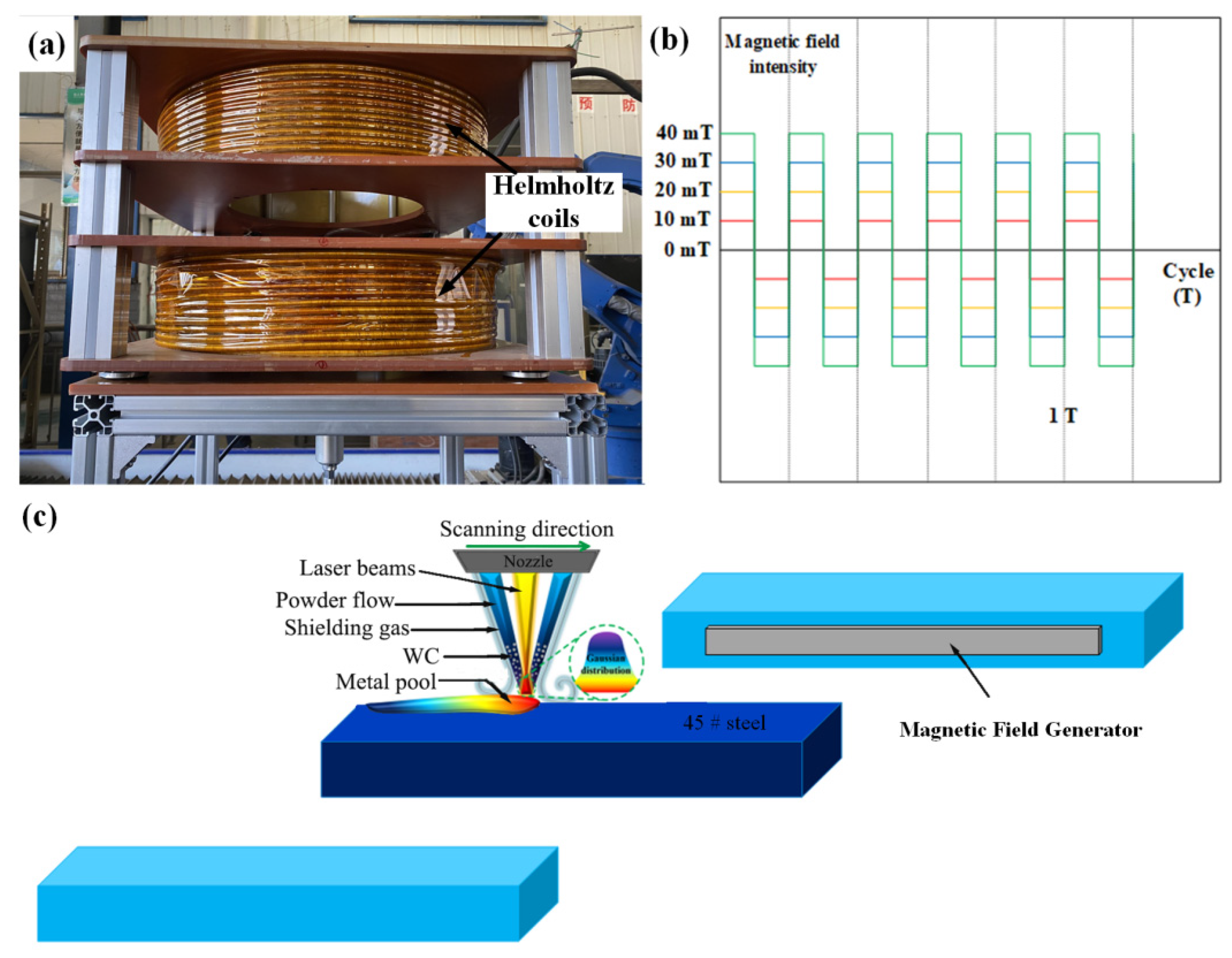
2. Experimental Section
3. Results and Discussion
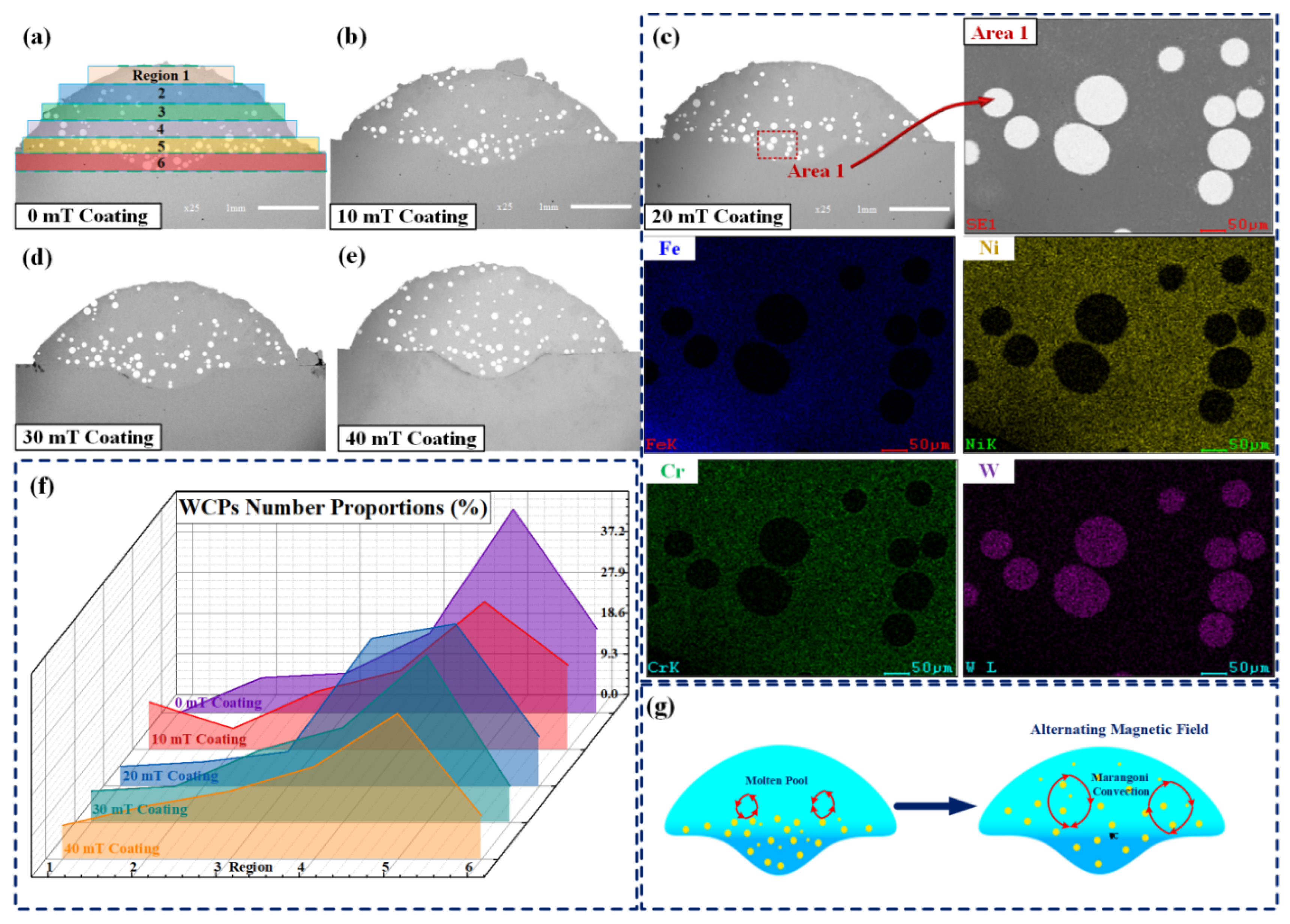
3.1. Macrostructure
3.2. Microstructure
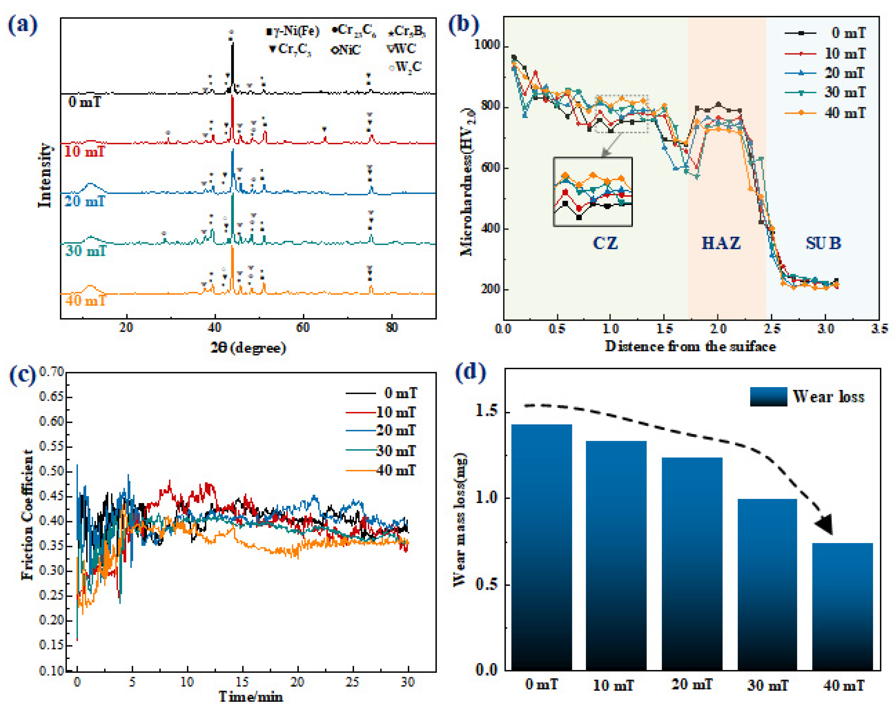
3.3. Microhardness
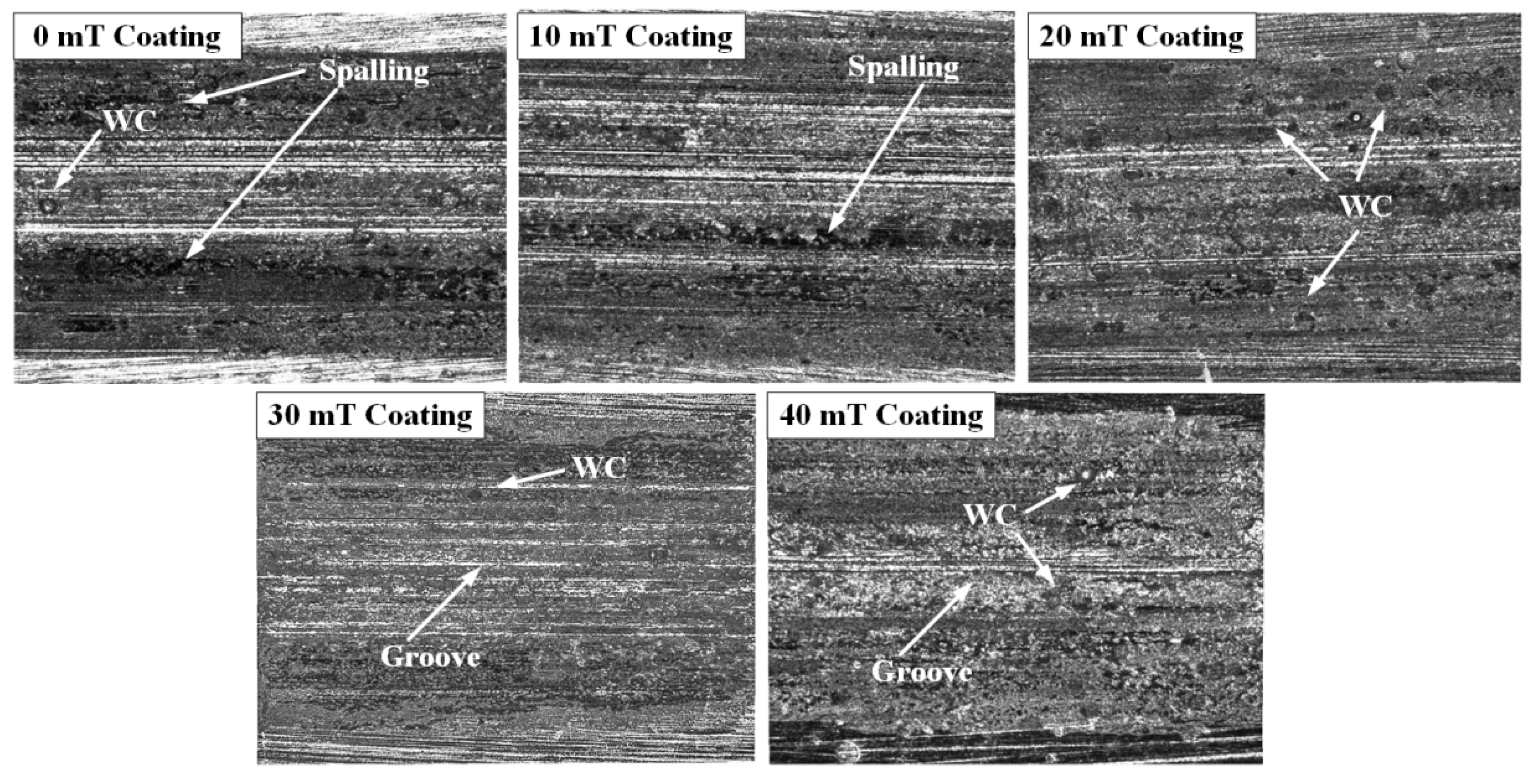
3.4. Wear Properties
4. Conclusions
- In terms of stirring in the laser pool, the alternating magnetic field intensifies the convection of liquid metal, stirring WC particles at the bottom and dispersing them to the middle and upper part, leading to a uniform distribution of WC particles.
- The alternating magnetic field significantly refines the carbide hard phase structure, and the phase composition of the coating does not change.
- The alternating magnetic field promotes the melting of WC particles, enhances the solution strengthening and dispersion strengthening and improves the coating hardness.
- The wear resistance of the coating is optimized when the alternating magnetic field is applied. As major wear forms, the adhesive and abrasive wear will gradually decrease as the magnetic field intensity increases.
Author Contributions
Funding
Institutional Review Board Statement
Informed Consent Statement
Data Availability Statement
Conflicts of Interest
References
- Zhang, J.C.; Shi, S.H.; Gong, Y.Q. Research Progress of Laser Cladding Technology. Surf. Technol. 2020, 10, 1–11. [Google Scholar] [CrossRef]
- Zhu, L.D.; Xue, P.S.; Lan, Q. Recent research and development status of laser cladding: A review. Opt. Laser Technol. 2021, 138, 106915. [Google Scholar] [CrossRef]
- Torims, T.; Pikurs, G.; Ratkus, A. Development of Technological Equipment to Laboratory Test In-situ Laser Cladding for Marine Engine Crankshaft Renovation. Procedia Eng. 2015, 100, 559–568. [Google Scholar] [CrossRef] [Green Version]
- Hao, L.H.; Cao, Y.B. Research on Development Situation in Preparation Technology of Carbide Reinforced Metal-based Laser Cladding Layer. Hot Work. Technol. 2022, 2, 17–20. [Google Scholar] [CrossRef]
- Li, W.Y.; Yang, X.F.; Xiao, J.P. Effect of WC mass fraction on the microstructure and friction properties of WC/Ni60 laser cladding layer of brake discs. Ceram. Int. 2021, 47, 28754–28763. [Google Scholar] [CrossRef]
- Farahmand, P.; Kovacevic, R. Laser cladding assisted with an induction heater (LCAIH) of Ni–60%WC coating. J. Mater. Process. Technol. 2015, 222, 244–258. [Google Scholar] [CrossRef]
- Si, S.H.; Yuan, X.M.; Liu, Y.L. Effect of laser power on microstructure and wear resistance of WCP/Ni cermet coating. J. Iron Steel Res. Int. 2006, 13, 74–78. [Google Scholar] [CrossRef]
- Wu, P.; Du, H.M.; Chen, X.L. Influence of WC particle behavior on the wear resistance properties of Ni–WC composite coatings. Wear 2004, 257, 142–147. [Google Scholar] [CrossRef]
- Wu, P.; Zhou, C.Z.; Tang, X.N. Laser alloying of a gradient metal-ceramic layer to enhance wear properties. Surf. Coat. Technol. 1995, 73, 111–114. [Google Scholar] [CrossRef]
- Liang, G.Y.; Wong, T.T. Investigation of microstructure of laser cladding Ni-WC layer on Al-Si alloy. J. Mater. Eng. Perform. 1997, 6, 41–45. [Google Scholar] [CrossRef]
- Anandkumar, R.; Almeida, A.; Vilar, R. Influence of powder particle injection velocity on the microstructure of Al–12Si/Si Cp coatings produced by laser cladding. Surf. Coat. Technol. 2009, 204, 285–290. [Google Scholar] [CrossRef]
- Hu, Y.; Wang, L.; Lou, F.X. Mechanism Study of Steady Magnetic Field Effect on Spherical WC Particle Distribution during Laser Melt Injection. J. Mech. Eng. 2021, 1, 240–248. [Google Scholar] [CrossRef]
- Fu, Y.M.; Qi, T.; Zong, L. Effects of Alternating Magnetic Field on Microstructures and Mechanics Properties of High Hardness Cladding Layers. China Mech. Eng. 2017, 28, 2378–2382. [Google Scholar] [CrossRef]
- Qi, Y.L.; Jia, G.L.; Zhang, G.Z. Effect of Electromagnetic Stirring on Liquid Metal Fluid Flow and Solidification Structure. Foundry Technol. 2005, 2, 118–120. [Google Scholar]
- Nguyen, H.L.; Van Nguyen, A.; Duy, H.L.; Nguyen, T.-H.; Tashiro, S.; Tanaka, M. Relationship among Welding Defects with Convection and Material Flow Dynamic Considering Principal Forces in Plasma Arc Welding. Metals 2021, 11, 1444. [Google Scholar] [CrossRef]
- Huu, M.N.; Van, A.N.; Van, T.N. Material Flow Behavior on Weld Pool Surface in Plasma Arc Welding Process Considering Dominant Driving Forces. Appl. Sci. 2020, 10, 3569. [Google Scholar] [CrossRef]
- Guo, C.; Chen, J.M.; Zhou, J.S. Effects of WC–Ni content on microstructure and wear resistance of laser cladding Ni-based alloys coating. Surf. Coat. Technol. 2012, 206, 2064–2071. [Google Scholar] [CrossRef]
- Imurai, S.; Thanachayanont, C.; Pearce, J.T.H. Effects of W on microstructure of ascast 28 wt.%Cr–2.6 wt.%C–(0–10)wt.%W irons. Mater. Charact. 2015, 99, 52–60. [Google Scholar] [CrossRef]
- Ma, Q.; Li, Y.; Wang, J. Investigation on cored-eutectic structure in Ni60/WC composite coatings fabricated by wide-band laser cladding. J. Alloys Compd. 2015, 645, 151–157. [Google Scholar] [CrossRef]
- Zhou, J.Z.; Xu, J.L.; Huang, S. Effect of laser surface melting with alternating magnetic field on wear and corrosion resistance of magnesium alloy. Surf. Coat. Technol. 2017, 309, 212–219. [Google Scholar] [CrossRef]
- Wang, C.; Zhang, S.; Zhang, C.H. Phase evolution and wear resistance of in situ synthesized V8C7 particles reinforcing Fe- based coating by laser cladding. Opt. Laser Technol. 2018, 105, 58–65. [Google Scholar] [CrossRef]
- Zhou, H.M.; Chen, Z.X.; Li, M.F. Effect of magnetic-electric-ultrasonic fields on microstructure and properties of Ni60A laser cladding coating. Mater. Lett. X 2022, 14, 100132. [Google Scholar] [CrossRef]
- Chen, Z.X.; Zhou, H.M.; Li, M.F. Effect of magnetic field waveform on microstructure and properties of laser cladding. Mater. Lett. X 2021, 11, 100084. [Google Scholar] [CrossRef]
- Zhang, M.N.; Wang, D.F.; He, L.J. Microstructure and elevated temperature wear behavior of laser-cladded AlCrFeMnNi high-entropy alloy coating. Opt. Laser Technol. 2022, 149, 107845. [Google Scholar] [CrossRef]
- Yang, J.X.; Bing, B.; Hua, K. Effect of metallurgical behavior on microstructure and properties of FeCrMoMn coatings prepared by high-speed laser cladding. Opt. Laser Technol. 2021, 144, 107431. [Google Scholar] [CrossRef]
- Shi, Y.M.; Li, J.B.; Zhang, J. Effect of La2O3 addition on wear properties of Ni60a/SiC coating using laser-cladding. Opt. Laser Technol. 2022, 148, 107640. [Google Scholar] [CrossRef]
- Wang, T.; Zhu, L.; Song, H.Y. Effect of WC-17Co content on microstructure and properties of IN718 composites prepared by laser cladding. Opt. Laser Technol. 2022, 148, 107780. [Google Scholar] [CrossRef]
- Wang, H.R.; Sun, Y.F.; Qiao, Y.Z. Effect of Ni-coated WC reinforced particles on microstructure and mechanical properties of laser cladding Fe-Co duplex coating. Opt. Laser Technol. 2021, 142, 107209. [Google Scholar] [CrossRef]


| Composition | C | Cr | Mn | Si | Ni | Fe |
|---|---|---|---|---|---|---|
| Percent | 0.42~0.50 | ≤0.25 | 0.50~0.80 | 0.17~0.37 | ≤0.25 | The rest |
| Composition | C | Cr | Si | B | Fe | Ni |
|---|---|---|---|---|---|---|
| Percent | 0.60~1.00 | 14.00~16.00 | 3.00~4.50 | 2.50~3.50 | ≤0.25 | The rest |
Publisher’s Note: MDPI stays neutral with regard to jurisdictional claims in published maps and institutional affiliations. |
© 2022 by the authors. Licensee MDPI, Basel, Switzerland. This article is an open access article distributed under the terms and conditions of the Creative Commons Attribution (CC BY) license (https://creativecommons.org/licenses/by/4.0/).
Share and Cite
Zhu, Y.; Zhou, H.; Chen, Z.; Wang, Z.; He, F.; Xu, C. Study on Microstructure and Properties of Ni60A/WC Composite Coating by Alternating-Magnetic-Field-Assisted Laser Cladding. Micromachines 2022, 13, 653. https://doi.org/10.3390/mi13050653
Zhu Y, Zhou H, Chen Z, Wang Z, He F, Xu C. Study on Microstructure and Properties of Ni60A/WC Composite Coating by Alternating-Magnetic-Field-Assisted Laser Cladding. Micromachines. 2022; 13(5):653. https://doi.org/10.3390/mi13050653
Chicago/Turabian StyleZhu, Yuxu, Houming Zhou, Zixin Chen, Zeda Wang, Fangjia He, and Caixing Xu. 2022. "Study on Microstructure and Properties of Ni60A/WC Composite Coating by Alternating-Magnetic-Field-Assisted Laser Cladding" Micromachines 13, no. 5: 653. https://doi.org/10.3390/mi13050653
APA StyleZhu, Y., Zhou, H., Chen, Z., Wang, Z., He, F., & Xu, C. (2022). Study on Microstructure and Properties of Ni60A/WC Composite Coating by Alternating-Magnetic-Field-Assisted Laser Cladding. Micromachines, 13(5), 653. https://doi.org/10.3390/mi13050653