
A Literature Survey with the Focus on Magnetically Coupled Wireless Power Transfer Systems Developed for Engineering and Biomedical Applications


Abstract
:1. Introduction
2. Integrated and Magnetically Coupled WPT for Engineering Applications

| Ref. | Scope | Contribution | Specifications |
|---|---|---|---|
| [1] | Providing fractional-order WPT System. | Transfer efficiency with output power are insensitive to the resonant frequency. | Meeting the requirements of efficiency with output power only change within 1% when the receiver resonant frequency is reduced by %. |
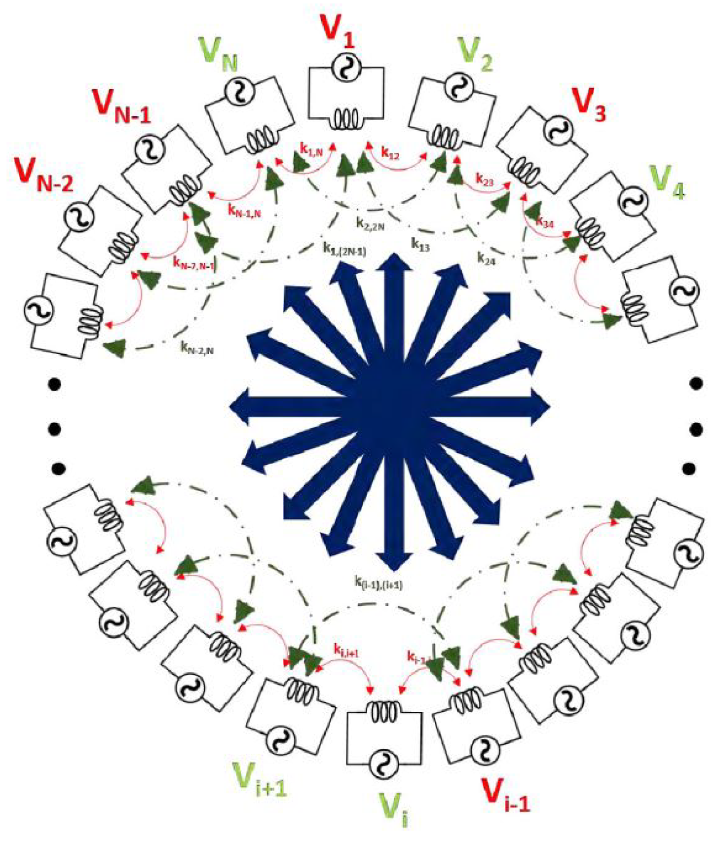
| [23] | Enabling WPT among multiple Tx and Rx simultaneously. | Presenting code division multiple access wireless power transfer (CDMA-WPT). | Achiving 5 W output power with about 75% efficiency. |
| [24] | Presenting hybrid load matching method for WPT system. | Achieving high efficiency specification. | 89% efficiency from 10 (527.8 W) to 600 (8.64 W) |
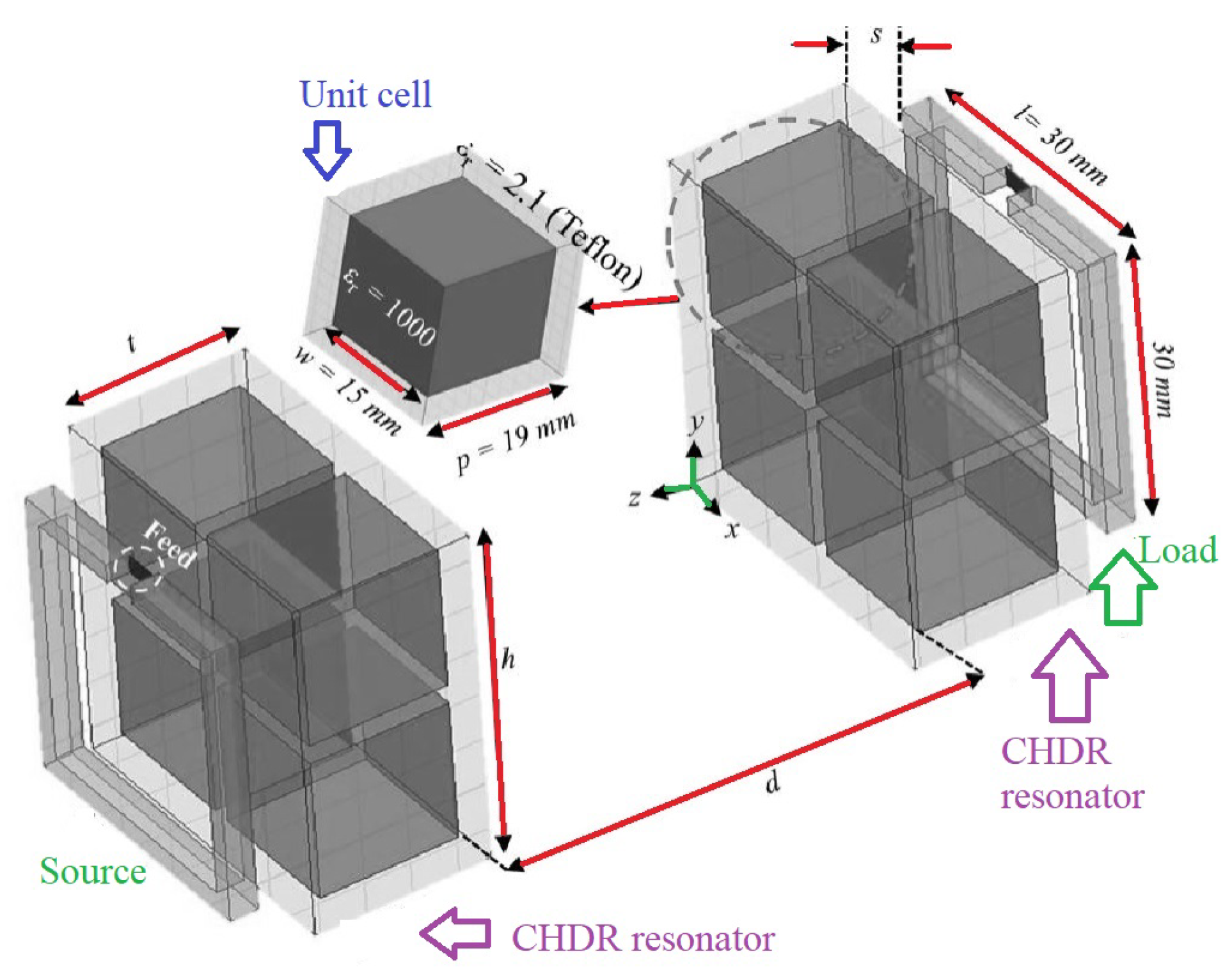
| [25] | Presenting a metamaterial-coupled WPT system. | Consisting of two cubic high-dielectric resonators. | More than 80% efficiency at short distances. |
| [26] | Integrating the compensated coil into the main coil structure. | Presenting a compact model results in reduced size. | Transferring 3.0 kW with 95.5% efficiency at an air gap of 150 mm. |
| [28] | Keeping high power transfer efficiency in the over-coupled region. | Presenting a closed-loop transmitter for wireless power transfer. | 60% efficiency at highly over-coupled spacings around 10 mm. |
| [29] | Presenting Tx- and Rx-coil for magnetic resonant WPT systems. | Presenting high efficiency at medium distance. | 96% efficiency at 50 mm and 39% efficiency at 300 mm. |
| [30] | Employing high temperature superconducting (HTS) wires in a WPT systems. | Enhancing the PTE in comparison with the conventional copper/Litz conductor. | PTE of 49.8% with the resonant frequency of 25 kHz. |
| [31] | Introducing strongly coupled magnetic resonance design. | Enhancing efficiency at larger distances. | 40% efficiency for the entire 360° misalignment. |
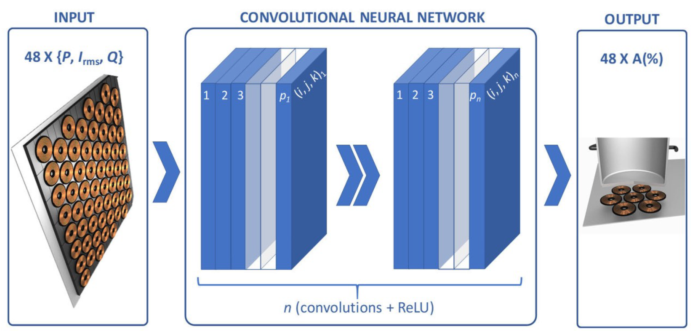
| [32] | Providing highly flexible cooking surfaces. | Composing of multi-coil structures that is based on deep-learning approach. | Estimating the magnetic coupling between the coil and the induction heating load. |
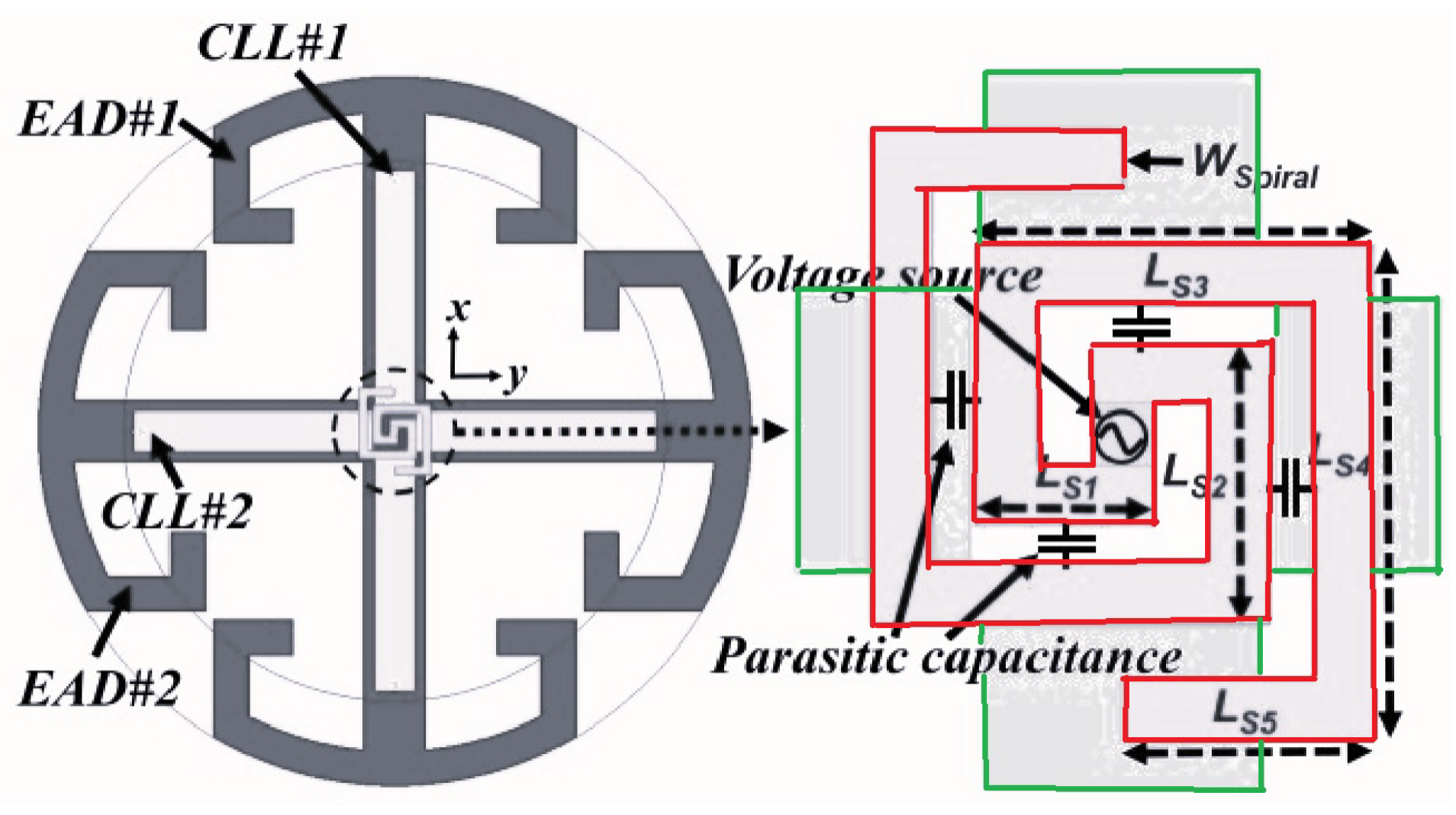
| [33] | Presenting small Huygens dual-functional WPT systems. | Combining a Huygens linearly polarized (HLP) antenna and a highly efficient HLP rectenna. | Peak gain of 2.7 dBi in the 915-MHz industrial, scientific, and medical radio band (ISM band). |
| [34] | Presenting small Huygens circularly polarized (HCP) rectenna. | Providing a near-field resonant parasitic where the rectifier circuit is highly capacitive. | Efficiency of 90.6% in the 915 MHz ISM band. |
| [35] | Presenting single-substrate Huygens dipole rectenna. | Consisting of two metamaterial inspired near-field resonant parasitic (NFRP) elements. | Efficiency of 88% with a gain of 4.6 dBi. |
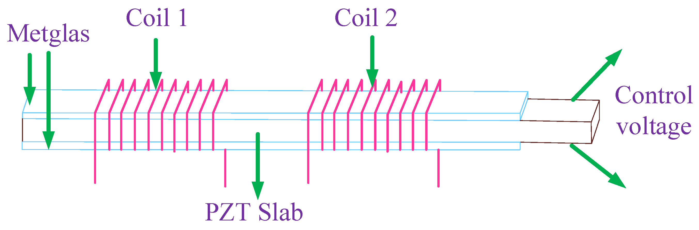
| [36] | Presenting dual-coil magnetic coupled resonance WPT system. | Presenting an energy transfer efficiency in overcoupled state. | Tunability of 56.5% in the low-frequency range and also a tunability of 16.6% in the high-frequency range. |
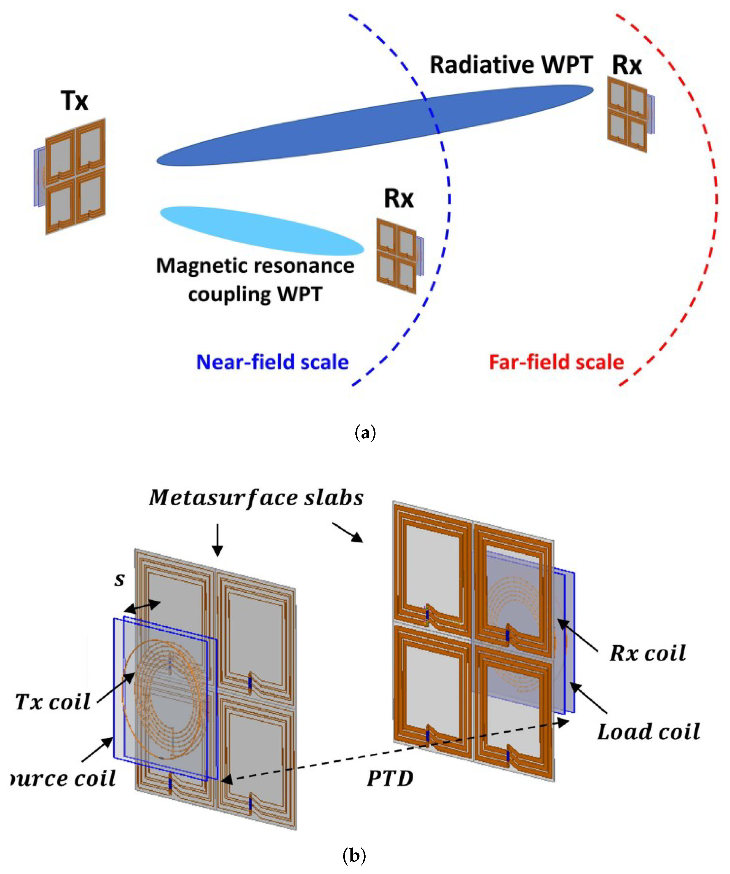
| [37] | Presenting metasurface-based multi-scale WPT system. | Working in both near-field scale and far-field scale. | Power transfer efficiency of 50.1 % at 433 MHz ISM band. |
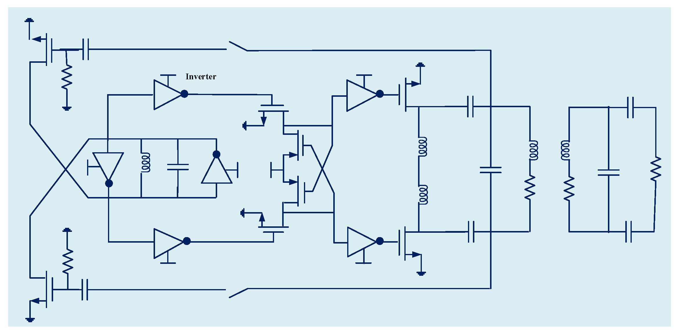
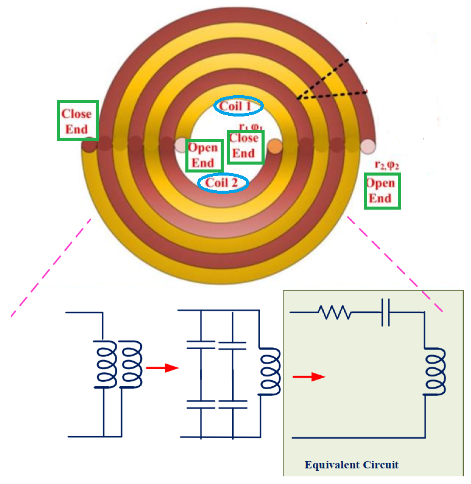
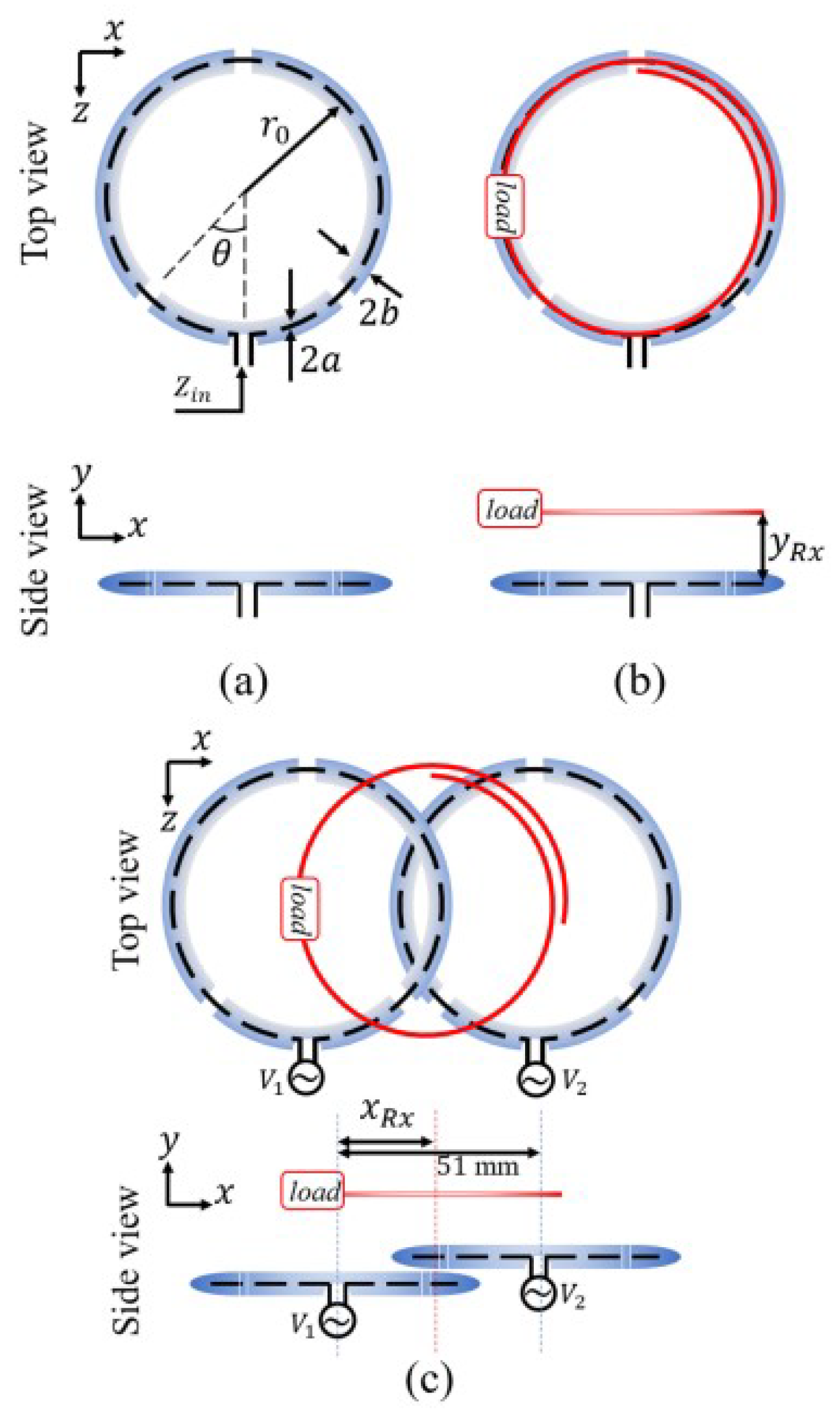
| [38] | Presenting WPT system based on the two high-impedance coil—cable loop antennas. | Presenting a high the input impedance for the Tx. | High-frequency range (around 280 MHz) with efficiency of 93%. |
3. Magnetically Coupled WPT Systems for Biomedical Applications
| Ref. | Scope | Contribution | Specifications |
|---|---|---|---|
| [2] | Presenting Tx array structure where lines are used instead of coils. | Keeping the line arrays antimisalignment. | Operating at Ku-band with CMOS Rx rectenna and a printed circuit board (PCB) Tx line array. The size of system is 100 µm × 100 µm where the gain is improved by 17.3 dB at a power transfer range of 2.5 mm. |
| [10] | Presenting a methodology for the design of printed magnetically coupled resonant considering human safety regulations. | Introducing a well-matched system with maximized power-transfer efficiency without the need for additional matching circuits connected to the system. | Working at 10 MHz with the input power at the range of 22–675 W. |
| [39] | Presenting a butterfly-shaped transmitting coil. | Enhancing the efficiency of the system in the distance, angle, and axial misalignment tolerances. | Presenting low specific absorption rate that is safe for medical applications. |
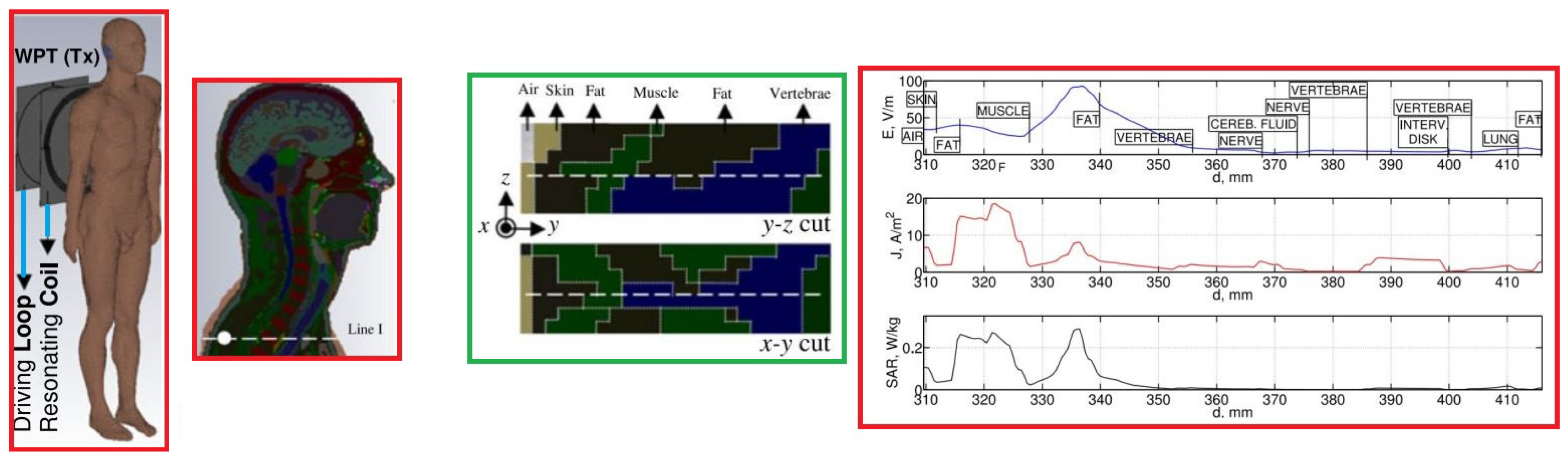
| [40] | Considering local exposure induced inside the human body at locations where the magnetic field polarization is either parallel or perpendicular. | At Presented locations where the H-field polarization is perpendicular to the body, the maximum E appears in deeper tissues compared to the locations having a parallel polarization. | Working at 1 MHz demonstrating that the non-uniform distribution and location of maximum of the E-field inside the body can be locally interpreted based on the tissues intrinsic impedance contrast. |
| [41] | Assessing the exposure due to a representative WPT system in three different human body models, i.e., adult male and female as well as a child | Demonstrating that the exposure to a child is the same or lower than in an adult. | Body dimensions play an important role being more pronounced for peak RMS values of and compared to those obtained for and . |
| [42] | Comparing the exposure of a grounded and ungrounded human body. | Presenting independently of the WPT system distance where the ground, peak dosimetric values are much higher in grounded than ungrounded scenarios. | is the most restrictive dosimetric quantity. |
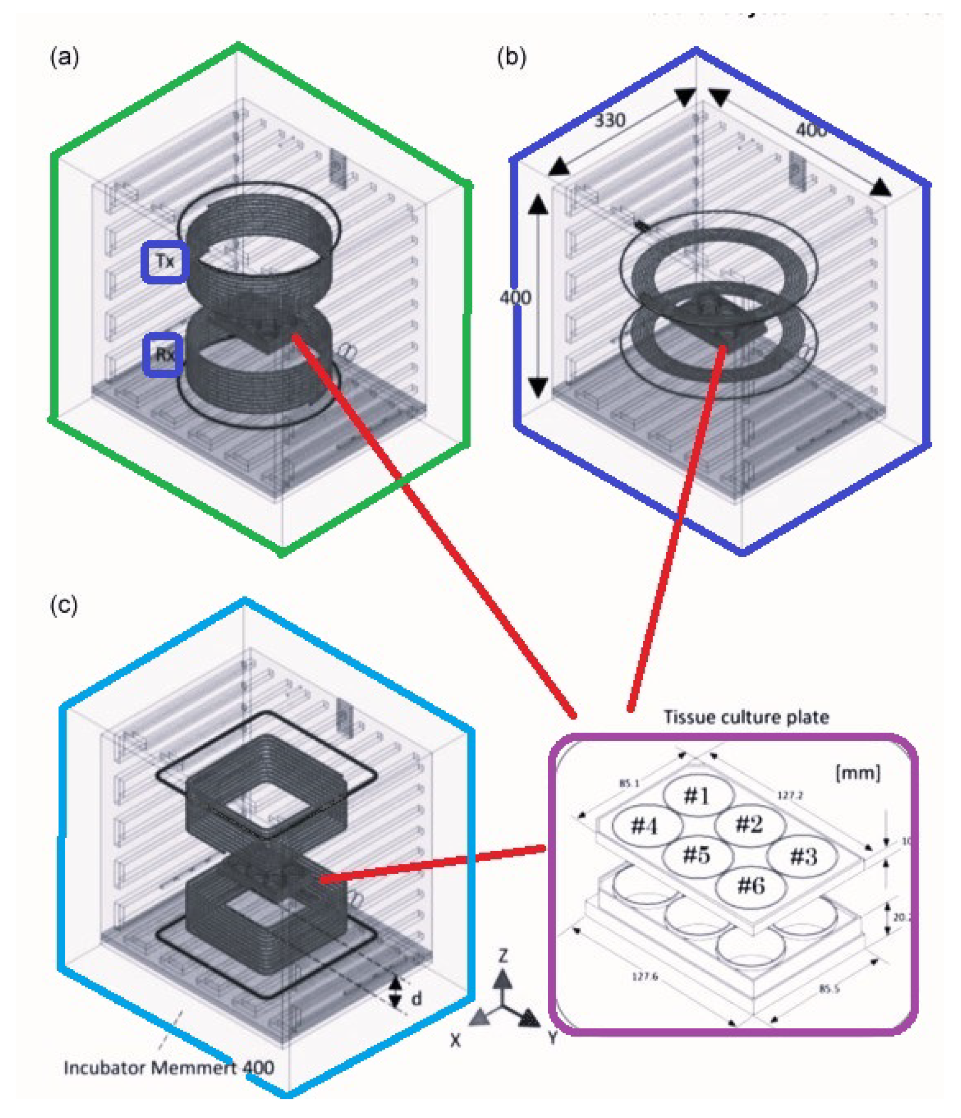
| [43] | Presenting the design of a resonant system for in vitro studies. | Equipping with cylindrical coils and square cross-sections led to a high EM field uniformity in the in vitro biological samples. | Operational frequency of 13.56 MHz demonstrating that the uniformities in E and SAR were limited among the wells to a maximum of 7.9% and 5.5%, respectively. |
| [44] | Presenting a complete WPT system with Tx and Rx chips. | Achieving output voltage regulations by the proposed constant-idle-time control. | 17.5% efficiency improvement where the chip is fabricated with 65-nm CMOS technology. |
| [45] | Presenting a resonant power converter. | Presenting an enhanced efficiency with minimum sensitivity. | Keeping soft switching against large variations in the loads. |
| [46] | Presenting a triple-loop WPT system. | Presenting a design where it opposes coupling and load variations and also compensates for changes in the environment surrounding the inductive link. | 10.5% efficiency at 13.56 MHz. |
| [48] | Presenting a magnetic resonant-based WPT system. | Providing enhanced efficiency with stable power. | Power efficiency of 79.2%. |
| [49] | Presenting a multicoil inductive power repeater system. | Performing coil as a power relay and also supplies energy. | Efficiency of 47.7% at a long distance of 51.5 cm. |
| [51] | Presenting a methdology for automated design of planar square-spiral coils. | Generating the idealized design parameters for enhancing power transfer efficiency. | Reducing in design time where all the design process can be done in few minutes and it is automated. |
| [55] | Presenting a theory for near-field resonant inductively coupled WPT. | Developing ultrasonic, mid-field, and far-field coupled WPT technologies. | Proving the efficiency of the presented method for the coupled WPT systems. |
| [56] | Presenting a 1-D lumped parameter model for passive capacitive parametric ultrasonic transducer. | Proving that the presented design does not need a DC bias or a permanent charge. | Presenting highly efficient power transfer. |
| [57] | Presenting the theory and design methodology of ultrasound WPT system. | Presenting iterative design procedure to enhance the power transfer efficiency. | 6 mW power with the power transfer efficiency of 0.14%. |
| [58] | Presenting implantable magnetic coupling resonate WPT system. | Employing conformal strongly coupled magnetic resonator coil for constructing power link. | 15.7 dB coupling enhancement. |
| [59] | Presenting an approach for simultaneous independent wireless power transferring. | Employing three coils at the Tx side. | Performing on the five loads, power transfer and force generation at frequency splitting. |
| [47] | Presenting a capacitively coupled conductive power transfer method. | Providing safe transfer of power into the body. | Running at 6.78 MHz, delivering 10 mW deep into the body. |
| [60] | Presenting a capacitive-coupled power transfer method. | Developing a resonant capacitive-coupling method for WPT system. | Efficiency more than 24%. |
| [62] | Presenting the results of pressure measurements after using impalnted sensor. | Presenting sensor activation by using inductive power transmission. | Resulting in power of 4.47 mW. |
| [63] | Presenting ultracompact design of biomedical implantable devices. | Designing integrated WPT with radio frequency transmissions. | Gain of −15.71 dBi with power of 115 mW. |
| [64] | Presenting a negative impedance converter. | Increasing the system efficiency that is based on the non-foster theory. | Introducing Efficiency more than 30% for a distance more than 100 mm. |
| [65] | Presenting an arm-implantable rectenna. | Supporting a planar inverted F-antenna and a rectifier. | ISM frequency band |
| [66] | Presenting a radiating near-field method. | Employing the principles of wireless power transfer using radiating antennas. | Performing up to 15 cm, showing a maximum loss of 7.5 dB. |
| [67] | Studying a wireless power link with circular polarization. | Employing the the system for far-field wireless power transmission. | 915 MHz frequency with input power of 25 dBm and peak gain of 8 dB. |
| [68] | Characterizing a compact rectennas for wireless power transmission application. | Employing rectennas for supplying power to a dcto-dc boost converter. | 868-MHz/915-MHz frequency band with power consumption of 9.45 mW and a dc voltage of 3 V. |
| [69] | Presenting a complete RF to DC wireless power transmission. | Employing implantable rectenna system. | 902.8–928 MHz frequency band with input power of −20 dBm. |
4. Conclusions
Author Contributions
Funding
Institutional Review Board Statement
Informed Consent Statement
Data Availability Statement
Conflicts of Interest
References
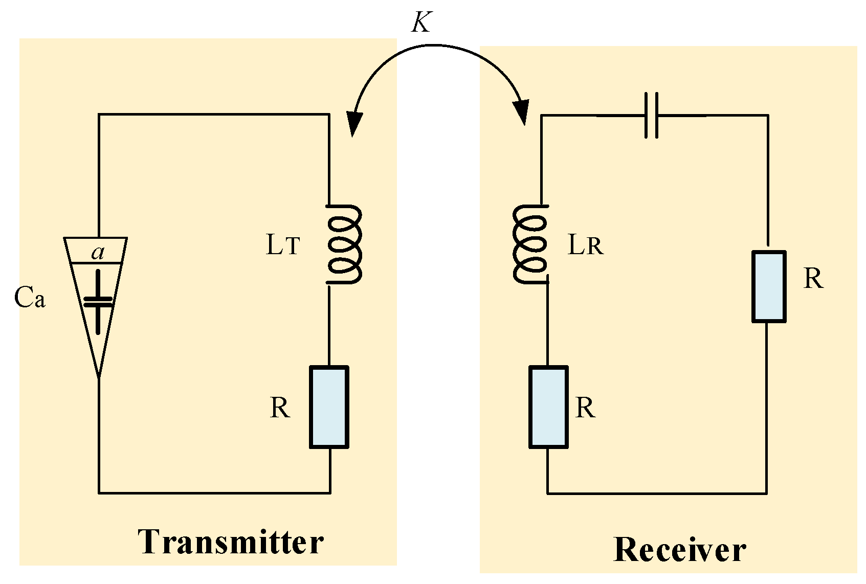
- Jiang, Y.; Zhang, B. A Fractional-Order Wireless Power Transfer System Insensitive to Resonant Frequency. IEEE Trans. Power Electron. 2020, 35, 5496–5505. [Google Scholar] [CrossRef]
- Zhao, B.; Kuo, N.C.; Niknejad, A.M.; Nikolić, B. A Line-Array Technique for Wireless Power Transfer Toward a 100 μm ×100 μm Coil Antenna. IEEE Trans. Microw. Theory Tech. 2020, 68, 353–364. [Google Scholar] [CrossRef]
- Alazzawi, Y.; Aono, K.; Scheller, E.L.; Chakrabartty, S. Exploiting Self-Capacitances for Wireless Power Transfer. In Proceedings of the 2020 IEEE International Symposium on Circuits and Systems (ISCAS), Seville, Spain, 12–14 October 2020; p. 1. [Google Scholar] [CrossRef]
- Li, X.; Zhang, Y.; Chen, S.; Zhang, X.; Tang, Y. Small-Signal Models of Resonant Converter with Consideration of Different Duty-Cycle Control Schemes. IEEE Trans. Power Electron. 2021, 36, 13234–13247. [Google Scholar] [CrossRef]
- Miao, Z.; Liu, D.; Gong, C. Efficiency Enhancement for an Inductive Wireless Power Transfer System by Optimizing the Impedance Matching Networks. IEEE Trans. Biomed. Circuits Syst. 2017, 11, 1160–1170. [Google Scholar] [CrossRef] [PubMed]
- Khalifa, A.; Karimi, Y.; Wang, Q.; Montlouis, W.; Garikapati, S.; Stanaćević, M.; Thakor, N.; Etienne-Cummings, R. The Microbead: A Highly Miniaturized Wirelessly Powered Implantable Neural Stimulating System. IEEE Trans. Biomed. Circuits Syst. 2018, 12, 521–531. [Google Scholar] [CrossRef] [PubMed]
- Kouhalvandi, L.; Matekovits, L.; Peter, I. Amplifiers in Biomedical Engineering: A Review from Application Perspectives. Sensors 2023, 23, 2277. [Google Scholar] [CrossRef] [PubMed]
- Kouhalvandi, L.; Matekovits, L.; Peter, I. Magic of 5G Technology and Optimization Methods Applied to Biomedical Devices: A Survey. Appl. Sci. 2022, 12, 7096. [Google Scholar] [CrossRef]
- Kouhalvandi, L.; Matekovits, L.; Peter, I. Deep Learning Assisted Automatic Methodology for Implanted MIMO Antenna Designs on Large Ground Plane. Electronics 2022, 11, 47. [Google Scholar] [CrossRef]
- Koohestani, M.; Zhadobov, M.; Ettorre, M. Design Methodology of a Printed WPT System for HF-Band Mid-Range Applications Considering Human Safety Regulations. IEEE Trans. Microw. Theory Tech. 2017, 65, 270–279. [Google Scholar] [CrossRef]
- Rouse, C.D.; Cove, S.R.; Salami, Y.; Arsenault, P.; Bartlett, A. Three-Phase Resonant Capacitive Power Transfer for Rotary Applications. IEEE J. Emerg. Sel. Top. Power Electron. 2022, 10, 160–169. [Google Scholar] [CrossRef]
- Mai, R.; Liu, Y.; Li, Y.; Yue, P.; Cao, G.; He, Z. An Active-Rectifier-Based Maximum Efficiency Tracking Method Using an Additional Measurement Coil for Wireless Power Transfer. IEEE Trans. Power Electron. 2018, 33, 716–728. [Google Scholar] [CrossRef]
- Li, K.; Lee, A.T.L.; Tan, S.C.; Hui, R.S.Y. Highly Efficient Single-Switch-Regulated Resonant Wireless Power Receiver With Hybrid Modulation. IEEE J. Emerg. Sel. Top. Power Electron. 2021, 9, 3770–3780. [Google Scholar] [CrossRef]
- Huang, Y.; Lee, A.T.L.; Tan, S.C.; Hui, S.Y. Highly Efficient Wireless Power Transfer System With Single-Switch Step-Up Resonant Inverter. IEEE J. Emerg. Sel. Top. Power Electron. 2021, 9, 1157–1168. [Google Scholar] [CrossRef]
- Thenathayalan, D.; Park, J.H. Highly Flexible High-Efficiency Multiple-Resonant Wireless Power Transfer System Using a Controllable Inductor. IEEE J. Emerg. Sel. Top. Power Electron. 2019, 7, 1914–1930. [Google Scholar] [CrossRef]
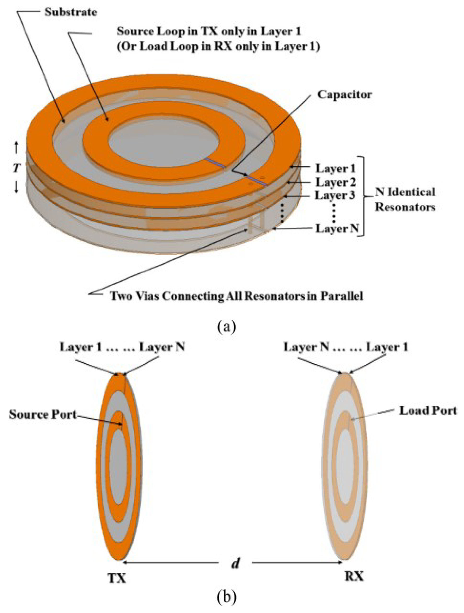
- Bao, K.; Zekios, C.L.; Georgakopoulos, S.V. Miniaturization of SCMR Systems Using Multilayer Resonators. IEEE Access 2019, 7, 143445–143453. [Google Scholar] [CrossRef]
- de Freitas Lima, G.; Godoy, R.B. Modeling and prototype of a dynamic wireless charging system using LSPS compensation topology. In Proceedings of the 2017 Brazilian Power Electronics Conference (COBEP), Juiz de Fora, Brazil, 19–22 November 2017; pp. 1–6. [Google Scholar] [CrossRef]
- Liu, D.; Hu, H.; Georgakopoulos, S.V. Misalignment Sensitivity of Strongly Coupled Wireless Power Transfer Systems. IEEE Trans. Power Electron. 2017, 32, 5509–5519. [Google Scholar] [CrossRef]
- Zhuang, Y.; Chen, A.; Xu, C.; Huang, Y.; Zhao, H.; Zhou, J. Range-Adaptive Wireless Power Transfer Based on Differential Coupling Using Multiple Bidirectional Coils. IEEE Trans. Ind. Electron. 2020, 67, 7519–7528. [Google Scholar] [CrossRef]
- Zhang, Y.; Chen, D.; Jiang, T. Robust Beamforming Design for Magnetic MIMO Wireless Power Transfer Systems. IEEE Trans. Signal Process. 2021, 69, 5066–5077. [Google Scholar] [CrossRef]
- Han, W.; Chau, K.T.; Cao, L.; Hua, Z.; Yang, T. S-CLC Compensated Wireless Power Transfer With Pulse-Frequency-Modulation Control for Dimmable Low-Pressure Sodium Lamps. IEEE Trans. Magn. 2021, 57, 1–7. [Google Scholar] [CrossRef]
- He, L.; Huang, X.; Cheng, B. Robust Class E2 Wireless Power Transfer System Based on Parity-Time Symmetry. IEEE Trans. Power Electron. 2022, 38, 4279–4288. [Google Scholar] [CrossRef]
- Sarin, A.; Avestruz, A.T. A Framework for Code Division Multiple Access Wireless Power Transfer. IEEE Access 2021, 9, 135079–135101. [Google Scholar] [CrossRef]
- Yang, H.; Li, Y.; Chen, J.; Shao, Y.; Yan, Z.; Mai, R.; He, Z. A Hybrid Load Matching Method for WPT Systems to Maintain High Efficiency Over Wide Load Range. IEEE Trans. Transp. Electrif. 2022, 9, 1993–2005. [Google Scholar] [CrossRef]
- Das, R.; Basir, A.; Yoo, H. A Metamaterial-Coupled Wireless Power Transfer System Based on Cubic High-Dielectric Resonators. IEEE Trans. Ind. Electron. 2019, 66, 7397–7406. [Google Scholar] [CrossRef]
- Kan, T.; Nguyen, T.D.; White, J.C.; Malhan, R.K.; Mi, C.C. A New Integration Method for an Electric Vehicle Wireless Charging System Using LCC Compensation Topology: Analysis and Design. IEEE Trans. Power Electron. 2017, 32, 1638–1650. [Google Scholar] [CrossRef]
- Li, Q.; Liang, Y.C. An Inductive Power Transfer System With a High-Q Resonant Tank for Mobile Device Charging. IEEE Trans. Power Electron. 2015, 30, 6203–6212. [Google Scholar] [CrossRef]
- Feng, G.; Sit, J.J. An Injection-Locked Wireless Power Transfer Transmitter With Automatic Maximum Efficiency Tracking. IEEE Trans. Ind. Electron. 2021, 68, 5733–5743. [Google Scholar] [CrossRef]
- Kim, T.H.; Yun, G.H.; Lee, W.Y.; Yook, J.G. Asymmetric Coil Structures for Highly Efficient Wireless Power Transfer Systems. IEEE Trans. Microw. Theory Tech. 2018, 66, 3443–3451. [Google Scholar] [CrossRef]
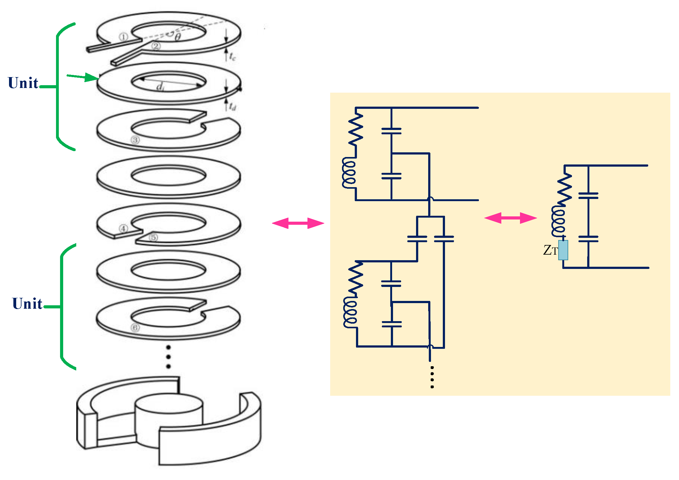
- Narayanamoorthi, R.; Juliet, A.V. Capacitor-Less High-Strength Resonant Wireless Power Transfer Using Open Bifilar Spiral Coil. IEEE Trans. Appl. Supercond. 2019, 29, 1–8. [Google Scholar] [CrossRef]
- Liu, D.; Georgakopoulos, S.V. Cylindrical Misalignment Insensitive Wireless Power Transfer Systems. IEEE Trans. Power Electron. 2018, 33, 9331–9343. [Google Scholar] [CrossRef]
- Lucia, O.; Navarro, D.; Guillén, P.; Sarnago, H.; Lucia, S. Deep Learning-Based Magnetic Coupling Detection for Advanced Induction Heating Appliances. IEEE Access 2019, 7, 181668–181677. [Google Scholar] [CrossRef]
- Lin, W.; Ziolkowski, R.W. Electrically Small Huygens Antenna-Based Fully-Integrated Wireless Power Transfer and Communication System. IEEE Access 2019, 7, 39762–39769. [Google Scholar] [CrossRef]
- Lin, W.; Ziolkowski, R.W. Electrically Small Huygens CP Rectenna With a Driven Loop Element Maximizes Its Wireless Power Transfer Efficiency. IEEE Trans. Antennas Propag. 2020, 68, 540–545. [Google Scholar] [CrossRef]
- Lin, W.; Ziolkowski, R.W. Electrically Small, Single-Substrate Huygens Dipole Rectenna for Ultracompact Wireless Power Transfer Applications. IEEE Trans. Antennas Propag. 2021, 69, 1130–1134. [Google Scholar] [CrossRef]
- Sun, C.; Yang, W.; He, Y.; Dong, C.; Liang, X.; Wei, Y.; Chen, H.; Sun, N.X. Electrostatically Tunable Mutual Inductance for Frequency Splitting Elimination in Wireless Power Transfer. IEEE Trans. Magn. 2022, 58, 1–6. [Google Scholar] [CrossRef]
- Lee, W.; Yoon, Y.K. High Efficiency Multiscale Wireless Power Transfer System Using Metasurface Slabs. IEEE Access 2022, 10, 46214–46223. [Google Scholar] [CrossRef]
- Mollaei, M.S.M.; Jayathurathnage, P.; Tretyakov, S.A.; Simovski, C.R. High-Impedance Wireless Power Transfer Transmitter Coils for Freely Positioning Receivers. IEEE Access 2021, 9, 42994–43000. [Google Scholar] [CrossRef]
- Ha-Van, N.; Seo, C. Modeling and Experimental Validation of a Butterfly-Shaped Wireless Power Transfer in Biomedical Implants. IEEE Access 2019, 7, 107225–107233. [Google Scholar] [CrossRef]
- Koohestani, M.; Ettorre, M.; Zhadobov, M. Local Dosimetry Applied to Wireless Power Transfer Around 10 MHz: Dependence on EM Parameters and Tissues Morphology. IEEE J. Electromagn. RF Microw. Med. Biol. 2018, 2, 123–130. [Google Scholar] [CrossRef]
- Koohestani, M.; Ettorre, M.; Zhadobov, M. Wireless power transfer: Are children more exposed than adults? In Proceedings of the 2017 11th European Conference on Antennas and Propagation (EUCAP), Paris, France, 19–24 March 2017; pp. 1039–1040. [Google Scholar] [CrossRef]
- Koohestani, M.; Ettorre, M.; Zhadobov, M. Wireless power transfer: Exposure assessment for grounded and ungrounded human body. In Proceedings of the 12th European Conference on Antennas and Propagation (EuCAP 2018), London, UK, 9–13 April 2018; pp. 1–4. [Google Scholar] [CrossRef]
- Koohestani, M.; Perdriau, R.; Le Dréan, Y.; Ettorre, M.; Zhadobov, M. A Resonant System for In Vitro Studies Emulating Wireless Power Transfer Exposure at 13.56 MHz. Bioelectromagnetics 2020, 41, 369–381. [Google Scholar] [CrossRef]
- Huang, C.; Kawajiri, T.; Ishikuro, H. A 13.56-MHz Wireless Power Transfer System With Enhanced Load-Transient Response and Efficiency by Fully Integrated Wireless Constant-Idle-Time Control for Biomedical Implants. IEEE J. Solid-State Circuits 2018, 53, 538–551. [Google Scholar] [CrossRef]
- Mashhadi, I.A.; Pahlevani, M.; Hor, S.; Pahlevani, H.; Adib, E. A New Wireless Power-Transfer Circuit for Retinal Prosthesis. IEEE Trans. Power Electron. 2019, 34, 6425–6439. [Google Scholar] [CrossRef]
- Lee, B.; Kiani, M.; Ghovanloo, M. A Triple-Loop Inductive Power Transmission System for Biomedical Applications. IEEE Trans. Biomed. Circuits Syst. 2016, 10, 138–148. [Google Scholar] [CrossRef]
- Sedehi, R.; Budgett, D.; Jiang, J.; Ziyi, X.; Dai, X.; Hu, A.P.; McCormick, D. A Wireless Power Method for Deeply Implanted Biomedical Devices via Capacitively Coupled Conductive Power Transfer. IEEE Trans. Power Electron. 2021, 36, 1870–1882. [Google Scholar] [CrossRef]
- Basar, M.R.; Ahmad, M.Y.; Cho, J.; Ibrahim, F. An Improved Wearable Resonant Wireless Power Transfer System for Biomedical Capsule Endoscope. IEEE Trans. Ind. Electron. 2018, 65, 7772–7781. [Google Scholar] [CrossRef]
- Qian, L.; Cui, K.; Xia, H.; Shao, H.; Wang, J.; Xia, Y. An Inductive Power Transfer System for Powering Wireless Sensor Nodes in Structural Health Monitoring Applications. IEEE Trans. Microw. Theory Tech. 2022, 70, 3732–3740. [Google Scholar] [CrossRef]
- Machnoor, M.; Gámez Rodríguez, E.S.; Kosta, P.; Stang, J.; Lazzi, G. Analysis and Design of a 3-Coil Wireless Power Transmission System for Biomedical Applications. IEEE Trans. Antennas Propag. 2019, 67, 5012–5024. [Google Scholar] [CrossRef]
- Kim, C.; Nichols, E.; Kim, B.N. Choosing the Optimal Power Coils Using Open-Source k-Oriented Design Automation. IEEE Trans. Biomed. Circuits Syst. 2021, 15, 159–170. [Google Scholar] [CrossRef]
- Matić, T.; Šneler, L.; Herceg, M. An Energy Efficient Multi-User Asynchronous Wireless Transmitter for Biomedical Signal Acquisition. IEEE Trans. Biomed. Circuits Syst. 2019, 13, 619–630. [Google Scholar] [CrossRef] [PubMed]
- Shi, L.; Yin, Z.; Jiang, L.; Li, Y. Advances in inductively coupled power transfer technology for rail transit. CES Trans. Electr. Mach. Syst. 2017, 1, 383–396. [Google Scholar] [CrossRef]
- Machnoor, M.; Kosta, P.; Monge, M.; Lazzi, G. Rectifier Design for Highly Loaded Inductive Wireless Power Transfer Systems for Biomedical Applications. IEEE J. Electromagn. RF Microw. Med. Biol. 2022, 6, 574–579. [Google Scholar] [CrossRef]
- Agarwal, K.; Jegadeesan, R.; Guo, Y.X.; Thakor, N.V. Wireless Power Transfer Strategies for Implantable Bioelectronics. IEEE Rev. Biomed. Eng. 2017, 10, 136–161. [Google Scholar] [CrossRef]
- Surappa, S.; Tao, M.; Degertekin, F.L. Analysis and Design of Capacitive Parametric Ultrasonic Transducers for Efficient Ultrasonic Power Transfer Based on a 1-D Lumped Model. IEEE Trans. Ultrason. Ferroelectr. Freq. Control 2018, 65, 2103–2112. [Google Scholar] [CrossRef]
- Kashani, Z.; Ilham, S.J.; Kiani, M. Design and Optimization of Ultrasonic Links With Phased Arrays for Wireless Power Transmission to Biomedical Implants. IEEE Trans. Biomed. Circuits Syst. 2022, 16, 64–78. [Google Scholar] [CrossRef]
- Li, L.; Liu, H.; Zhang, H.; Xue, W. Efficient Wireless Power Transfer System Integrating With Metasurface for Biological Applications. IEEE Trans. Ind. Electron. 2018, 65, 3230–3239. [Google Scholar] [CrossRef]
- Narayanamoorthi, R.; Juliet, A.V.; Chokkalingam, B. Frequency Splitting-Based Wireless Power Transfer and Simultaneous Propulsion Generation to Multiple Micro-Robots. IEEE Sens. J. 2018, 18, 5566–5575. [Google Scholar] [CrossRef]
- Narayanamoorthi, R. Modeling of Capacitive Resonant Wireless Power and Data Transfer to Deep Biomedical Implants. IEEE Trans. Compon. Packag. Manuf. Technol. 2019, 9, 1253–1263. [Google Scholar] [CrossRef]
- Ye, Z.; Yang, M.; Chen, P.Y. Multi-Band Parity-Time-Symmetric Wireless Power Transfer Systems for ISM-Band Bio-Implantable Applications. IEEE J. Electromagn. RF Microw. Med. Biol. 2022, 6, 196–203. [Google Scholar] [CrossRef]
- Khan, M.W.A.; Björninen, T.; Sydänheimo, L.; Ukkonen, L. Remotely Powered Piezoresistive Pressure Sensor: Toward Wireless Monitoring of Intracranial Pressure. IEEE Microw. Wirel. Compon. Lett. 2016, 26, 549–551. [Google Scholar] [CrossRef]
- Sun, G.; Muneer, B.; Li, Y.; Zhu, Q. Ultracompact Implantable Design With Integrated Wireless Power Transfer and RF Transmission Capabilities. IEEE Trans. Biomed. Circuits Syst. 2018, 12, 281–291. [Google Scholar] [CrossRef]
- Kim, T.H.; Yun, G.H.; Lee, W.; Yook, J.G. Highly Efficient WPT System With Negative Impedance Converter for Q-factor Improvement. IEEE Access 2019, 7, 108750–108760. [Google Scholar] [CrossRef]
- Bakogianni, S.; Koulouridis, S. A Dual-Band Implantable Rectenna for Wireless Data and Power Support at Sub-GHz Region. IEEE Trans. Antennas Propag. 2019, 67, 6800–6810. [Google Scholar] [CrossRef]
- DeLong, B.J.; Kiourti, A.; Volakis, J.L. A Radiating Near-Field Patch Rectenna for Wireless Power Transfer to Medical Implants at 2.4 GHz. IEEE J. Electromagn. RF Microw. Med. Biol. 2018, 2, 64–69. [Google Scholar] [CrossRef]
- Liu, C.; Zhang, Y.; Liu, X. Circularly Polarized Implantable Antenna for 915 MHz ISM-Band Far-Field Wireless Power Transmission. IEEE Antennas Wirel. Propag. Lett. 2018, 17, 373–376. [Google Scholar] [CrossRef]
- Okba, A.; Takacs, A.; Aubert, H. Compact Rectennas for Ultra-Low-Power Wireless Transmission Applications. IEEE Trans. Microw. Theory Tech. 2019, 67, 1697–1707. [Google Scholar] [CrossRef]
- Ding, S.; Koulouridis, S.; Pichon, L. Implantable rectenna system for biomedical wireless applications. In Proceedings of the 2019 IEEE Wireless Power Transfer Conference (WPTC), London, UK, 18–21 June 2019; pp. 454–457. [Google Scholar] [CrossRef]


Disclaimer/Publisher’s Note: The statements, opinions and data contained in all publications are solely those of the individual author(s) and contributor(s) and not of MDPI and/or the editor(s). MDPI and/or the editor(s) disclaim responsibility for any injury to people or property resulting from any ideas, methods, instructions or products referred to in the content. |
© 2023 by the authors. Licensee MDPI, Basel, Switzerland. This article is an open access article distributed under the terms and conditions of the Creative Commons Attribution (CC BY) license (https://creativecommons.org/licenses/by/4.0/).
Share and Cite
Kouhalvandi, L.; Ozoguz, S.; Koohestani, M. A Literature Survey with the Focus on Magnetically Coupled Wireless Power Transfer Systems Developed for Engineering and Biomedical Applications. Micromachines 2023, 14, 786. https://doi.org/10.3390/mi14040786
Kouhalvandi L, Ozoguz S, Koohestani M. A Literature Survey with the Focus on Magnetically Coupled Wireless Power Transfer Systems Developed for Engineering and Biomedical Applications. Micromachines. 2023; 14(4):786. https://doi.org/10.3390/mi14040786
Chicago/Turabian StyleKouhalvandi, Lida, Serdar Ozoguz, and Mohsen Koohestani. 2023. "A Literature Survey with the Focus on Magnetically Coupled Wireless Power Transfer Systems Developed for Engineering and Biomedical Applications" Micromachines 14, no. 4: 786. https://doi.org/10.3390/mi14040786
APA StyleKouhalvandi, L., Ozoguz, S., & Koohestani, M. (2023). A Literature Survey with the Focus on Magnetically Coupled Wireless Power Transfer Systems Developed for Engineering and Biomedical Applications. Micromachines, 14(4), 786. https://doi.org/10.3390/mi14040786