


Effects of Mo Addition on Microstructure and Corrosion Resistance of Cr25-xCo25Ni25Fe25Mox High-Entropy Alloys via Directed Energy Deposition
 ,
,  ,
,  and
and
Abstract
1. Introduction
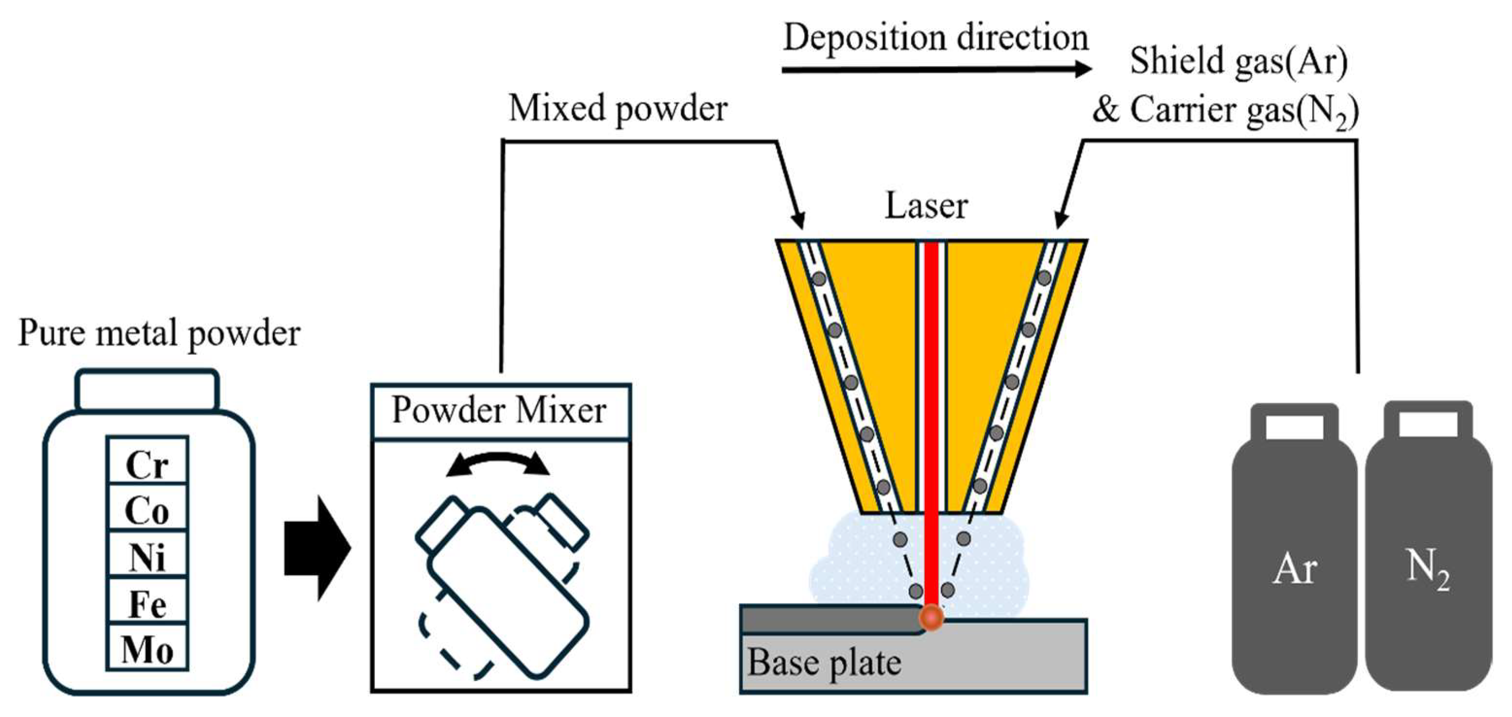
2. Directed Energy Deposition (DED) Process
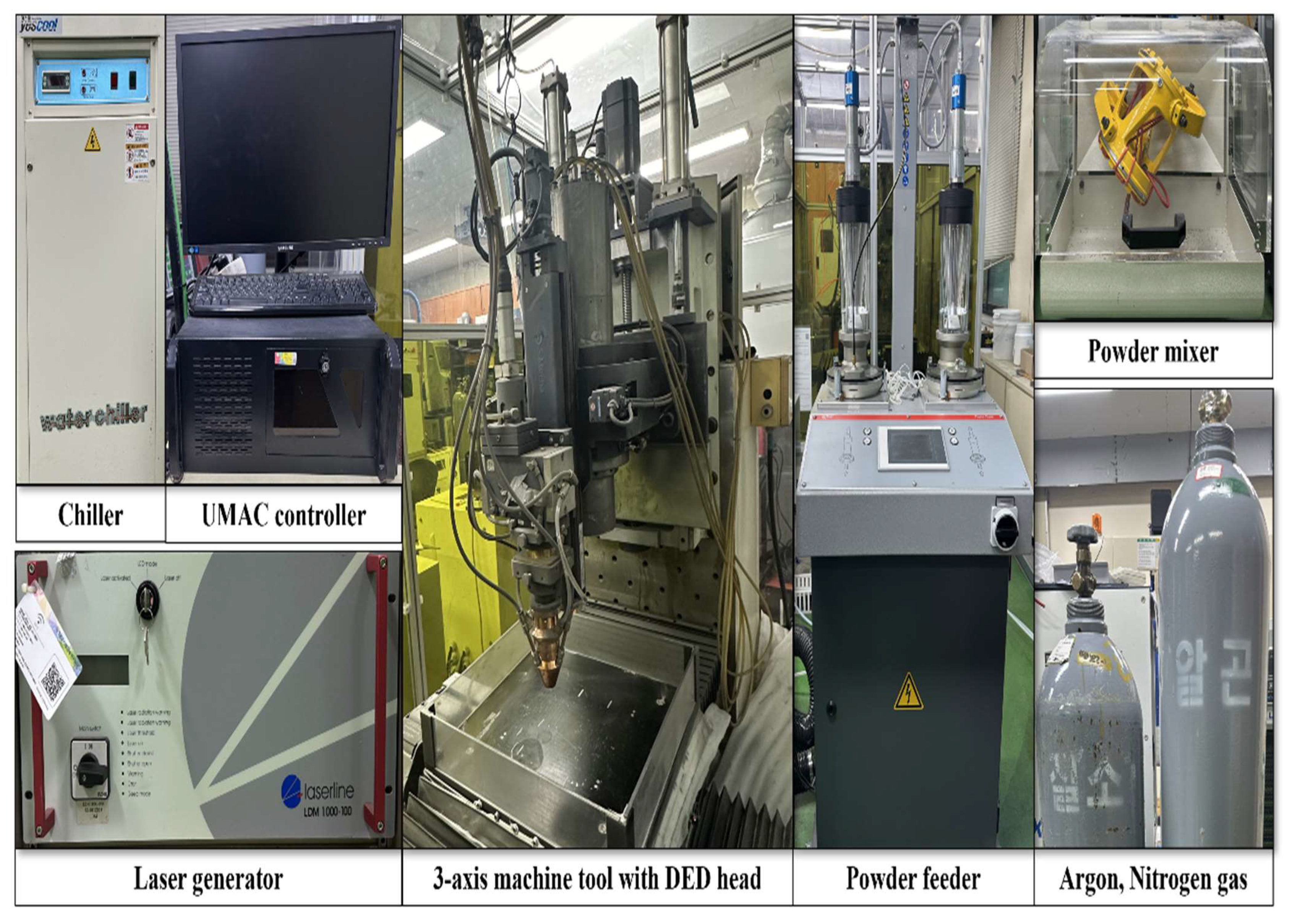
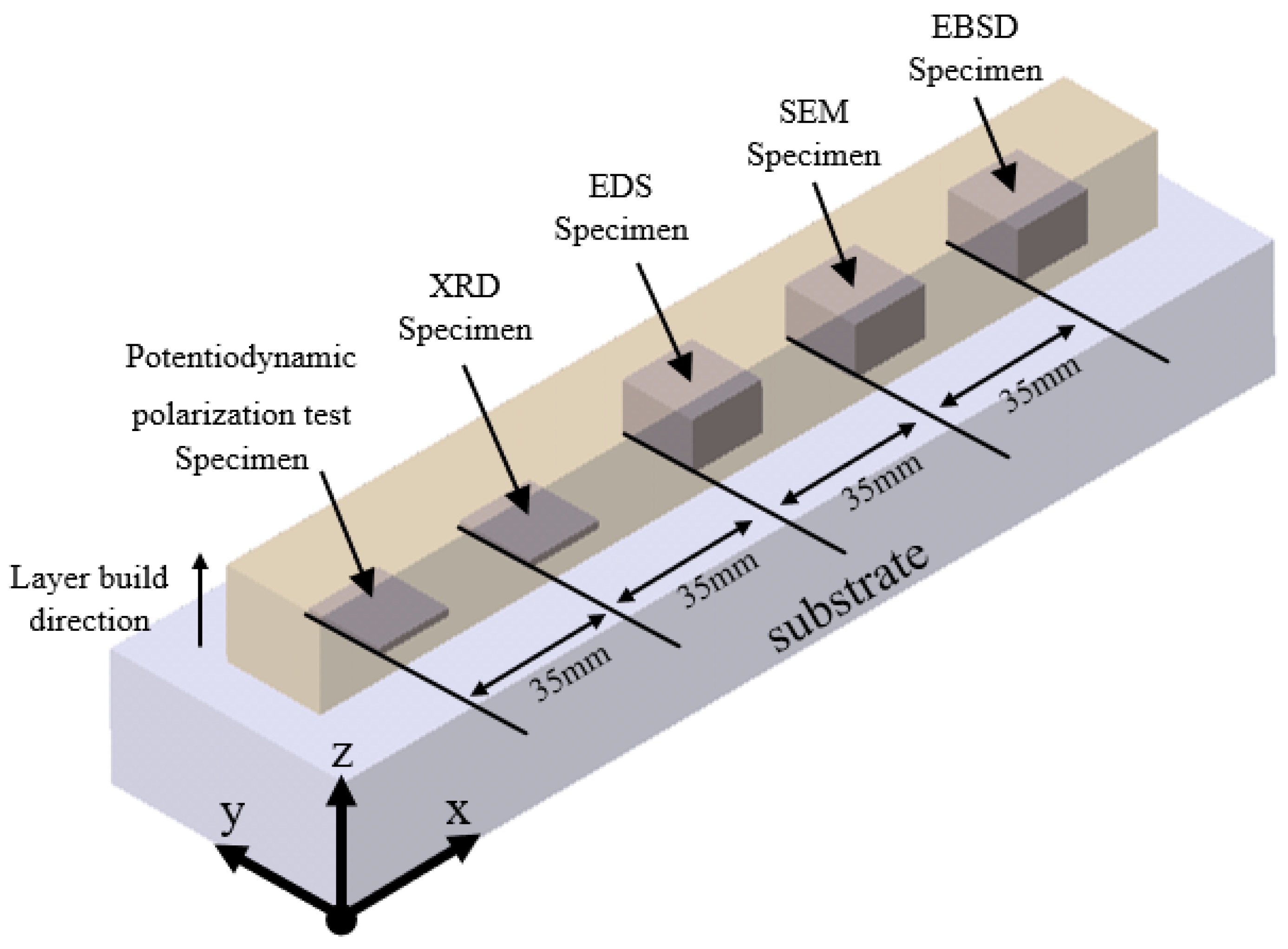
2.1. Experimental
2.2. Materials and Experiment
3. Results and Discussion
3.1. Microstructure
3.1.1. X-ray Diffraction (XRD) Analysis
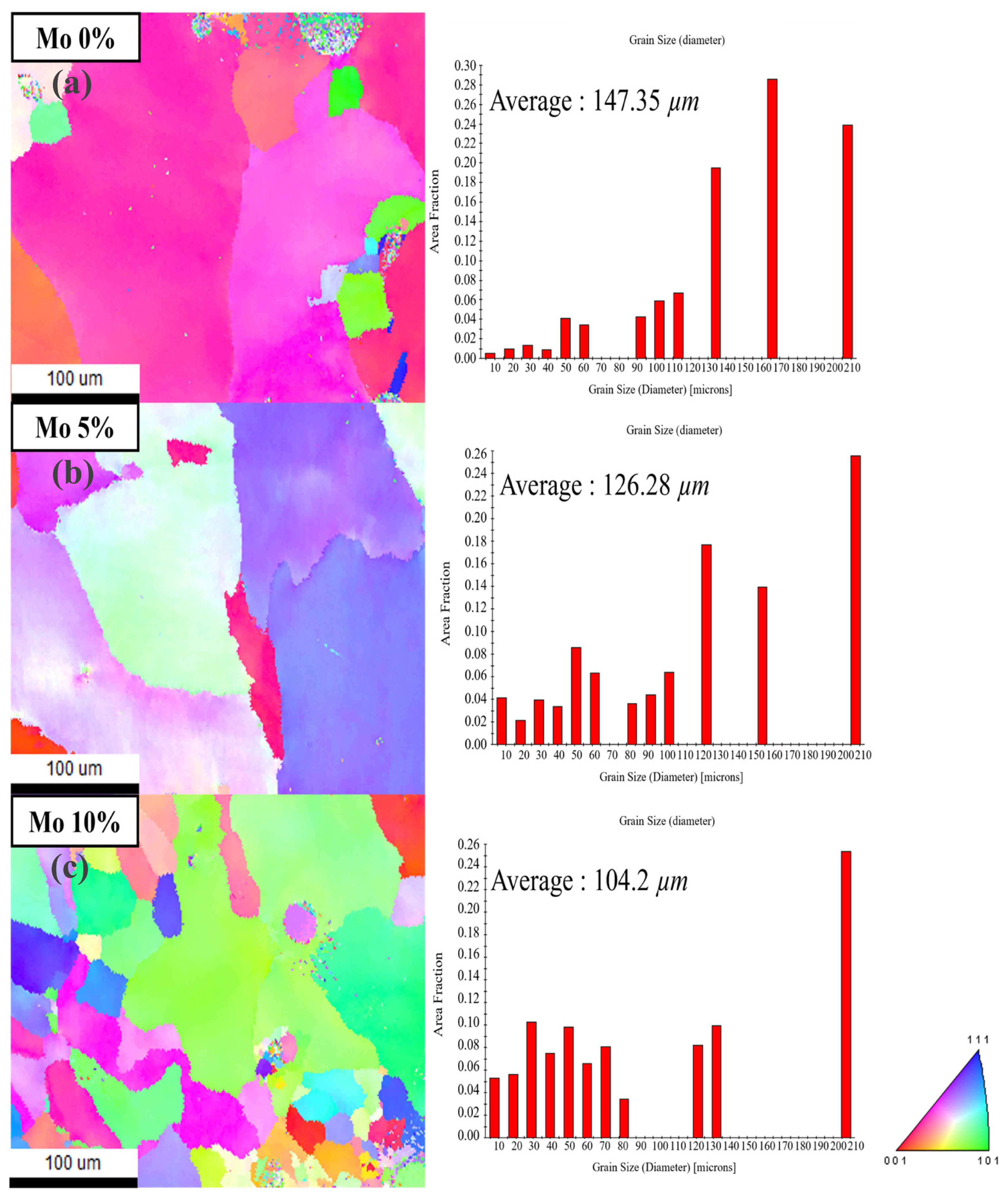
3.1.2. Electron Backscatter Diffraction (EBSD) Analysis
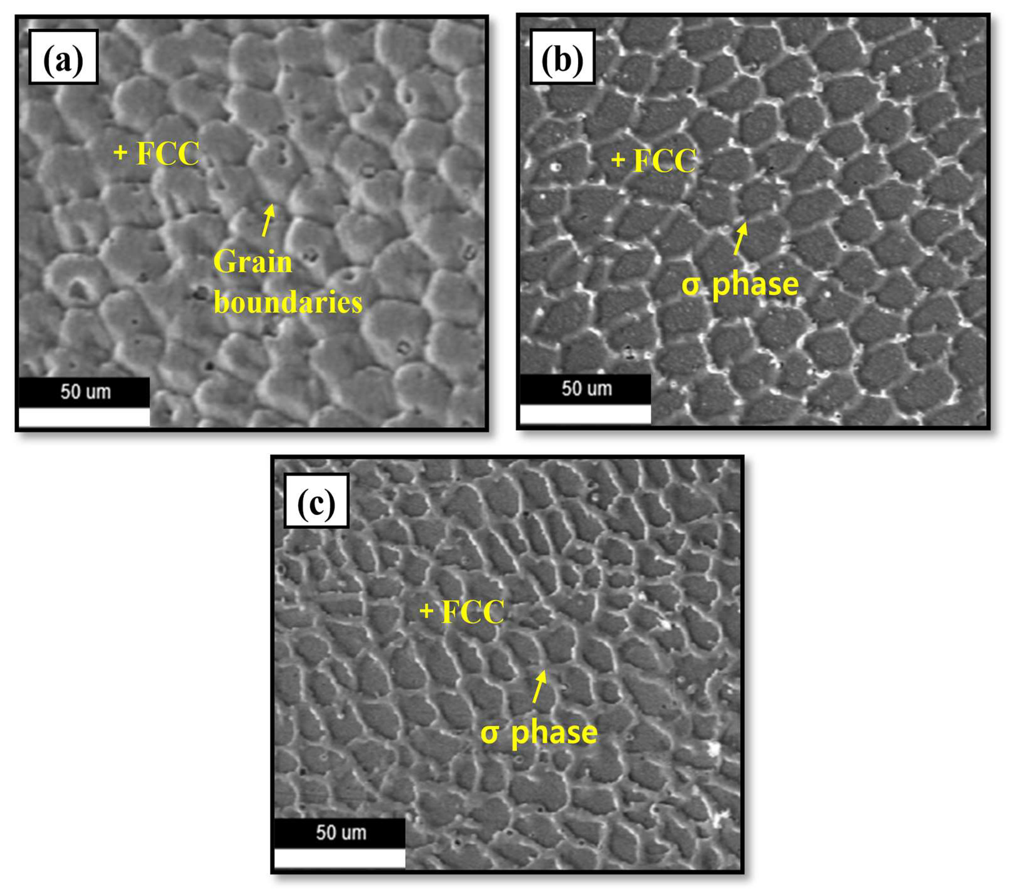
3.1.3. Scanning Electron Microscopy (SEM) Analysis
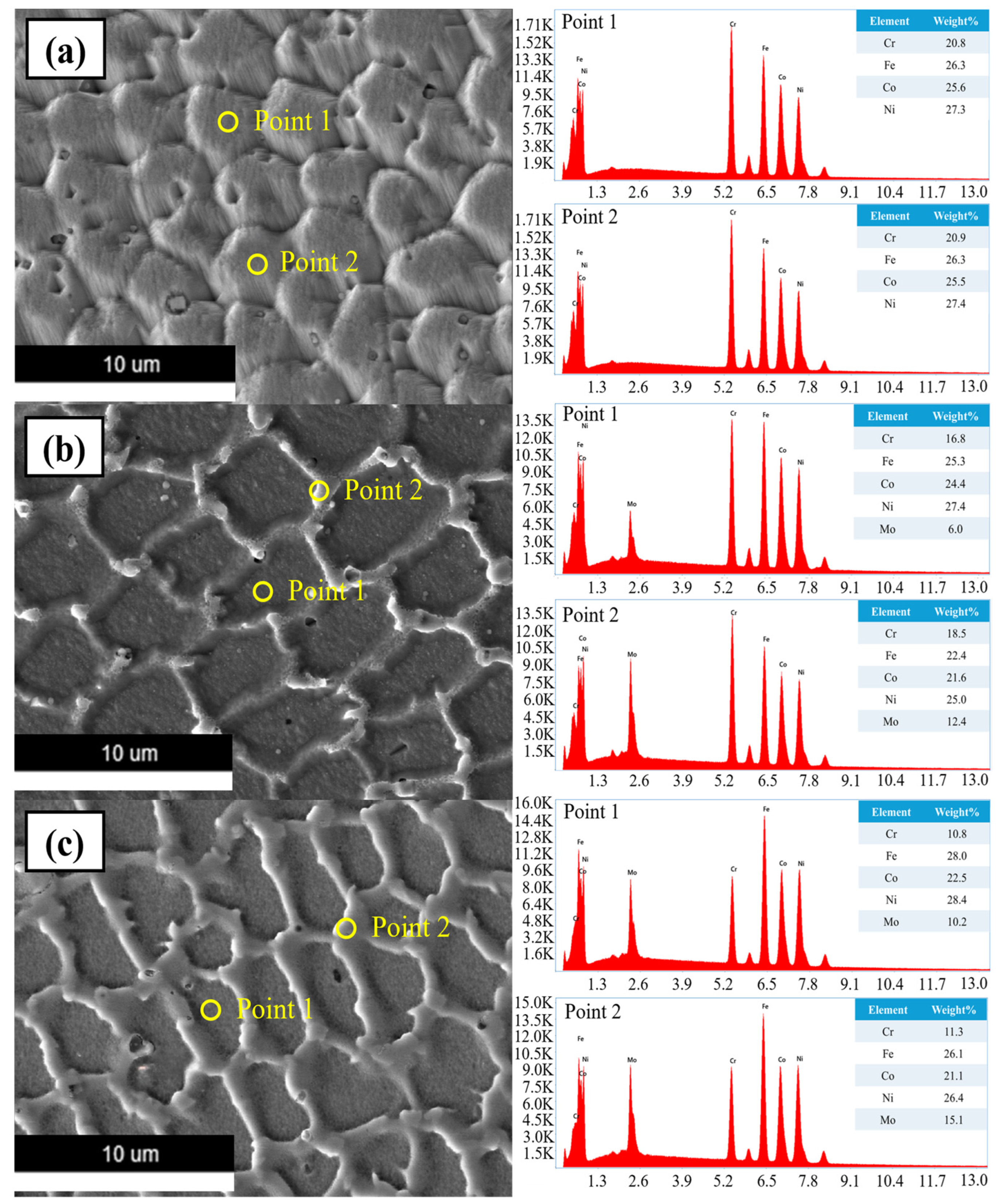
3.1.4. Energy-Dispersive X-ray Spectroscopy (EDS) Analysis
3.2. Mechanical Properties
3.2.1. Tensile Strength
3.2.2. Potentiodynamic Polarization Test
4. Conclusions
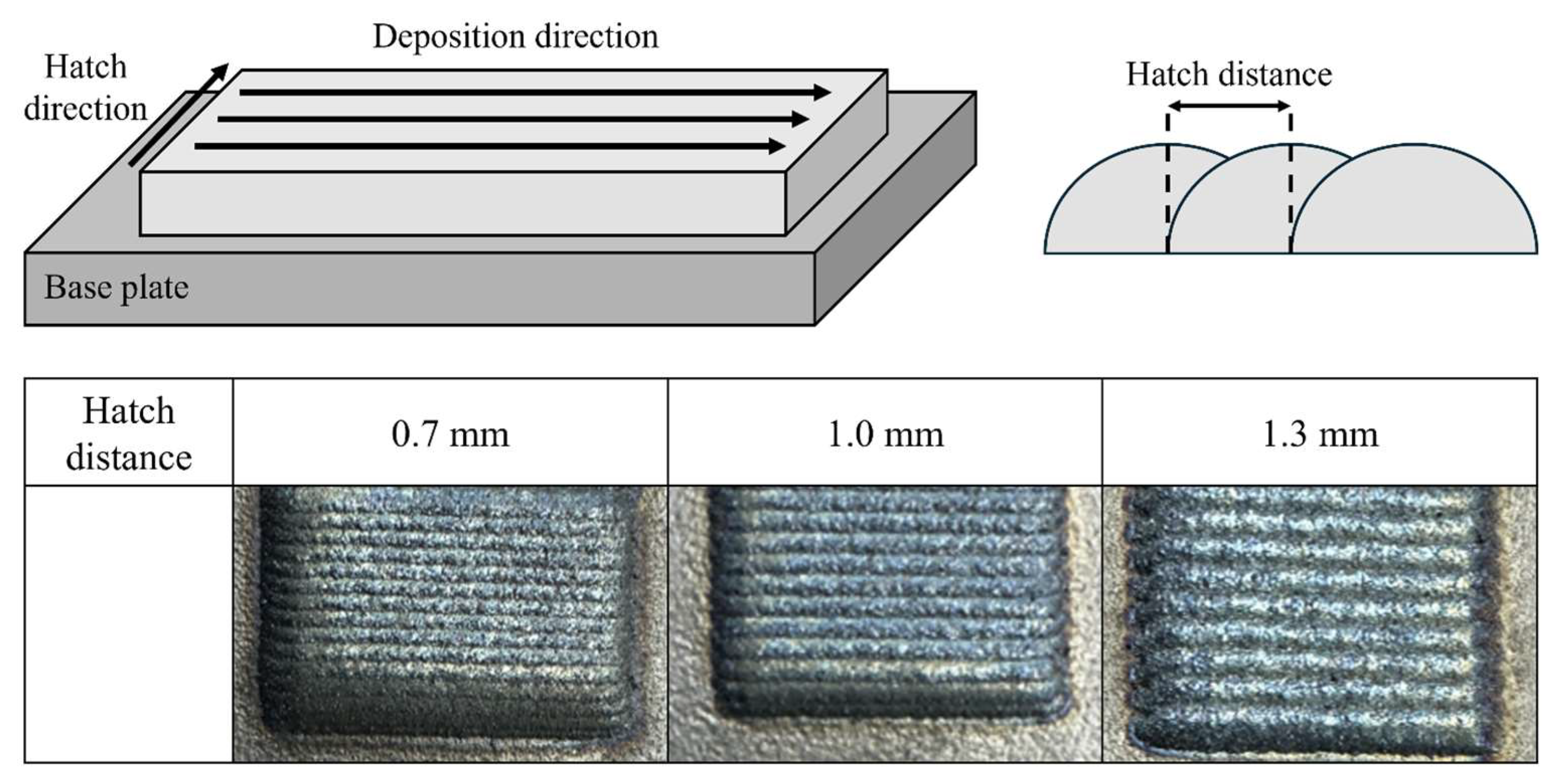
- 1.
- An initial experiment was conducted to obtain the ideal hatch distance for Cr25-xCo25Ni25Fe25Mox (at x = 0, 5, 10%). The findings demonstrated that a hatch distance of 1.0 mm was optimal since it achieved homogeneity without excessive overlap or edge collapse. Reduced uniformity was observed while using a hatch distance of 1.3 mm, but a hatch distance of 0.7 mm resulted in increased height due to excessive overlap, which ultimately caused edge collapse.
- 2.
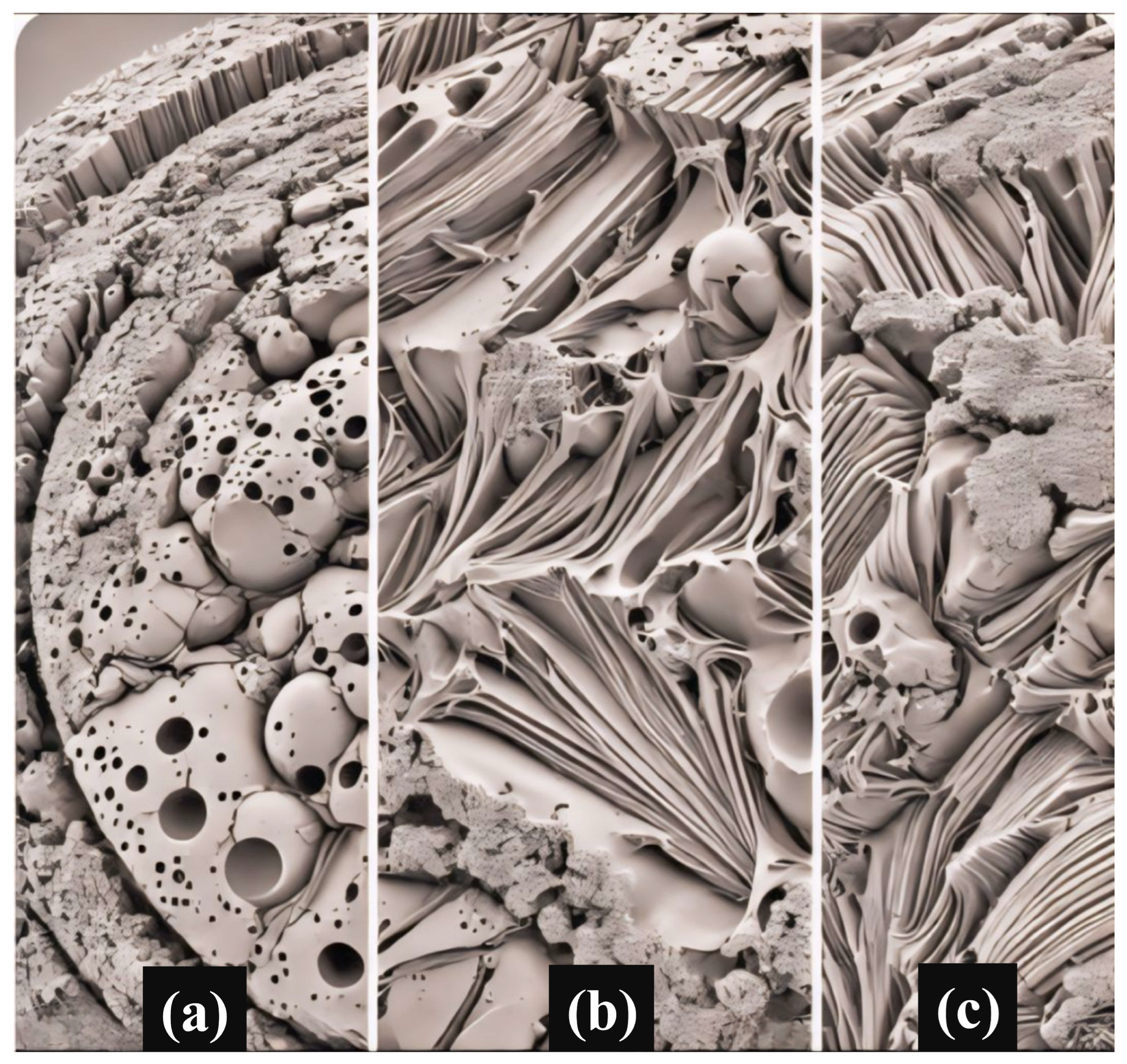
- XRD investigation verified the existence of the FCC single-phase structure in the 0% Mo specimen, whereas the 5% and 10% Mo samples exhibited the creation of the FCC + σ dual-phase structure as a result of the interaction between Mo and Cr. Analysis using EBSD revealed that the average grain sizes for 0%, 5%, and 10% Mo were 147.35 µm, 126.28 µm, and 104.2 µm, respectively. This indicates that the grain size decreases as the Mo concentration increases. The creation of the FCC + σ dual-phase structure was identified as the cause of this grain refinement. SEM investigation demonstrated that the presence of Mo resulted in the formation of the σ phase between FCC phases, as observed using electron microscopy. The volume fraction of the σ phase increased proportionally with the Mo level. The chemical composition differences between the FCC and σ phases were confirmed by EDS analysis, which indicated the interaction between Mo and Cr in the production of the σ phase.
- 3.
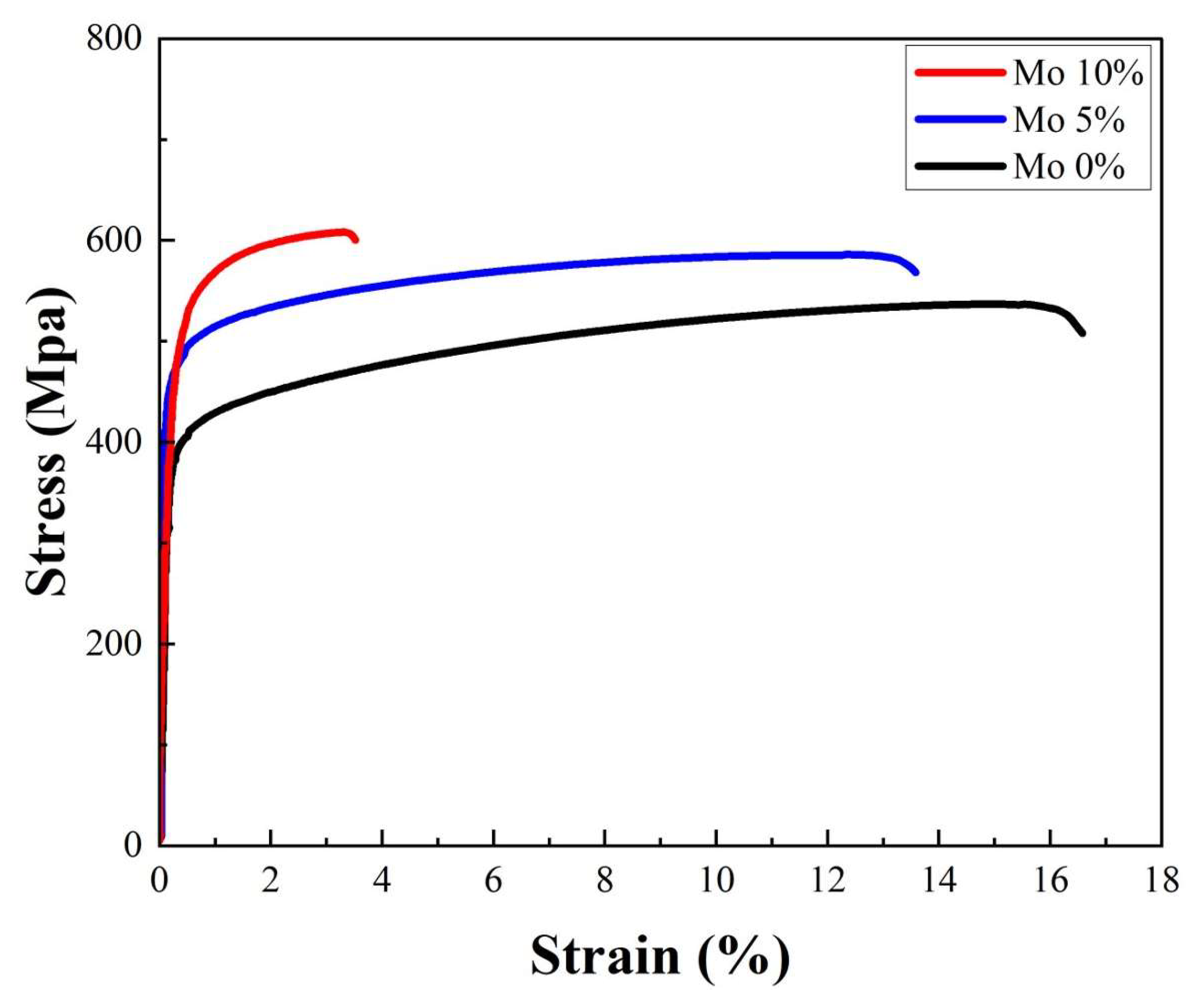
- Using Mo greatly enhanced the mechanical properties of the alloys. The inclusion of Mo facilitated the formation of the σ phase, resulting in an enhanced grain boundary-strengthening effect and improved mechanical strength. The results of the tensile test demonstrated that the inclusion of Mo increased YS and UTS. The YS and UTS of the specimens with 0% Mo were measured to be 388 MPa and 524 MPa, respectively. By including 5% Mo, the YS and UTS experienced significant enhancements, reaching 466 MPa and 574 MPa, respectively. These increases correspond to a 20.1% increase in YS and a 9.5% increase in UTS. By including 10% Mo, the YS and UTS were elevated to 514 MPa and 631 MPa, respectively. This corresponds to 32.5% and 20.4% enhancements compared to the alloy with 0% Mo.
- 4.
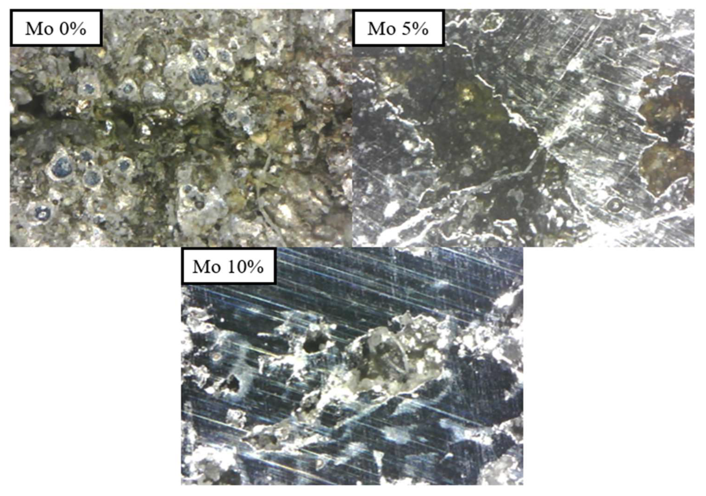
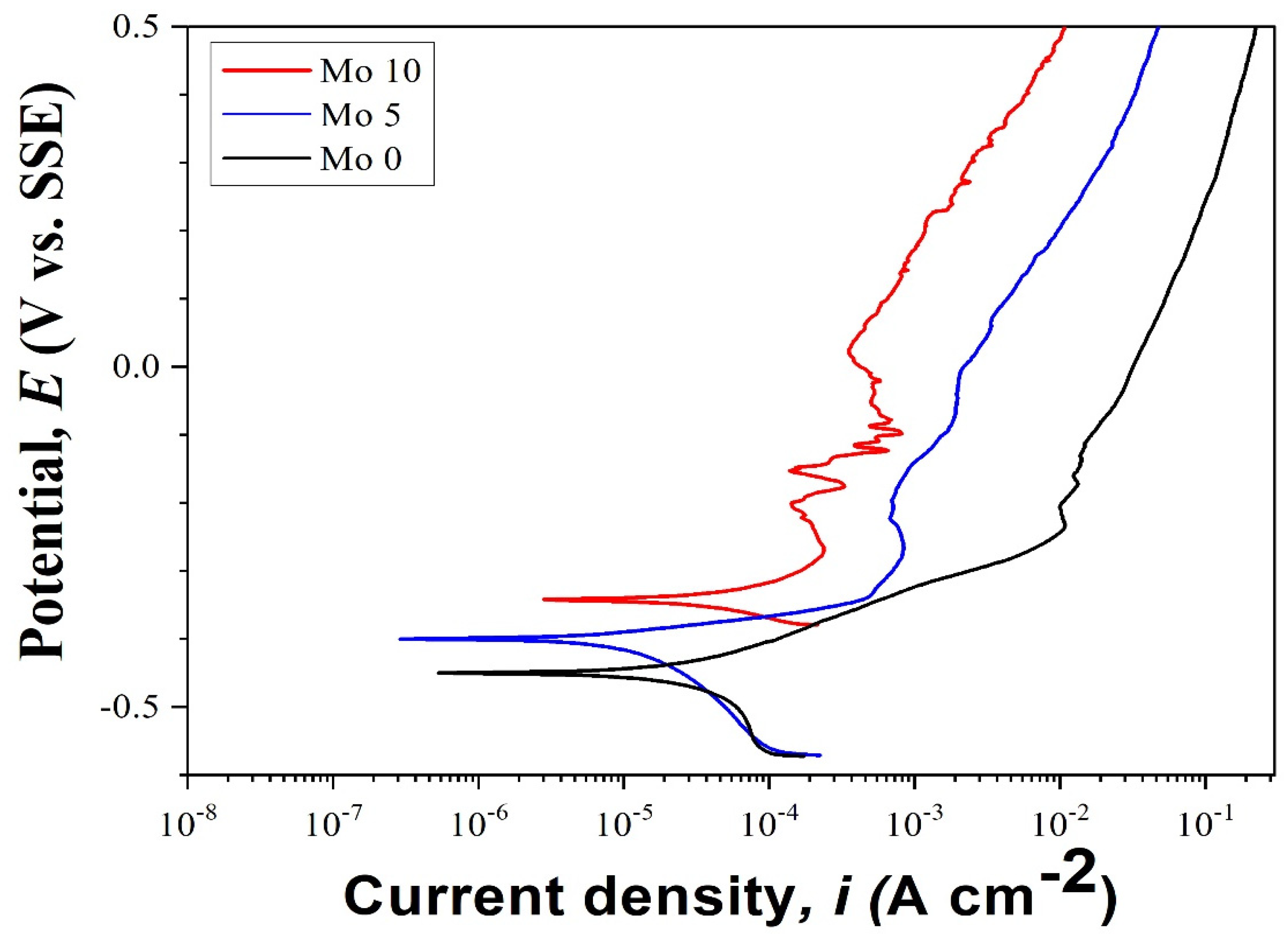
- The corrosion resistance of HEAs was determined by applying potentiodynamic polarization tests in a 3.5-weight percent sodium chloride (NaCl) solution. The results showed that the inclusion of Mo significantly improved the initial corrosion resistance of the alloys. The 5% Mo alloy demonstrated a higher Ecorr and a lower Icorr than the 0% Mo alloy, suggesting a superior ability to resist initial corrosion. The 10% Mo alloy exhibited the highest corrosion potential and the lowest current density, leading to the slowest corrosion growth and the highest resistance to initial corrosion.
Author Contributions
Funding
Data Availability Statement
Conflicts of Interest
References
- George, E.P.; Curtin, W.A.; Tasan, C.C. High Entropy Alloys: A Focused Review of Mechanical Properties and Deformation Mechanisms. Acta Mater. 2020, 188, 435–474. [Google Scholar] [CrossRef]
- Liu, N.; Chen, C.; Chang, I.; Zhou, P.; Wang, X. Compositional Dependence of Phase Selection in CoCrCu0.1FeMoNi-Based High-Entropy Alloys. Materials 2018, 11, 1290. [Google Scholar] [CrossRef] [PubMed]
- Fan, A.C.; Li, J.H.; Tsai, M.H. On the Phase Constituents of Three CoCrFeNiX (X = Cr, Mo, W) High-Entropy Alloys after Prolonged Annealing. Mater. Chem. Phys. 2022, 276, 125431. [Google Scholar] [CrossRef]
- Zhang, Y.; Zhou, Y.J.; Lin, J.P.; Chen, G.L.; Liaw, P.K. Solid-Solution Phase Formation Rules for Multi-Component Alloys. Adv. Eng. Mater. 2008, 10, 534–538. [Google Scholar] [CrossRef]
- Zhang, Y.; Zuo, T.T.; Tang, Z.; Gao, M.C.; Dahmen, K.A.; Liaw, P.K.; Lu, Z.P. Microstructures and Properties of High-Entropy Alloys. Prog. Mater. Sci. 2014, 61, 1–93. [Google Scholar] [CrossRef]
- Cantor, B. Multicomponent High-Entropy Cantor Alloys. Prog. Mater. Sci. 2021, 120, 100754. [Google Scholar] [CrossRef]
- Owen, L.R.; Pickering, E.J.; Playford, H.Y.; Stone, H.J.; Tucker, M.G.; Jones, N.G. An Assessment of the Lattice Strain in the CrMnFeCoNi High-Entropy Alloy. Acta Mater. 2017, 122, 11–18. [Google Scholar] [CrossRef]
- Wong, K.V.; Hernandez, A. A Review of Additive Manufacturing. ISRN Mech. Eng. 2012, 2012, 1–10. [Google Scholar] [CrossRef]
- Bidulsky, R.; Gobber, F.S.; Bidulska, J.; Ceroni, M.; Kvackaj, T.; Grande, M.A. Coated Metal Powders for Laser Powder Bed Fusion (L-PBF) Processing: A Review. Metals 2021, 11, 1831. [Google Scholar] [CrossRef]
- Ahn, D.G. Directed Energy Deposition (DED) Process: State of the Art. Int. J. Precis. Eng. Manuf. Green Technol. 2021, 8, 703–742. [Google Scholar] [CrossRef]
- Chen, S.; Tong, Y.; Liaw, P.K. Additive Manufacturing of High-Entropy Alloys: A Review. Entropy 2018, 20, 937. [Google Scholar] [CrossRef] [PubMed]
- Dai, C.; Zhao, T.; Du, C.; Liu, Z.; Zhang, D. Effect of Molybdenum Content on the Microstructure and Corrosion Behavior of FeCoCrNiMox High-Entropy Alloys. J. Mater. Sci. Technol. 2020, 46, 64–73. [Google Scholar] [CrossRef]
- Fu, Y.; Li, J.; Luo, H.; Du, C.; Li, X. Recent Advances on Environmental Corrosion Behavior and Mechanism of High-Entropy Alloys. J. Mater. Sci. Technol. 2021, 80, 217–233. [Google Scholar] [CrossRef]
- Wang, Q.; Amar, A.; Jiang, C.; Luan, H.; Zhao, S.; Zhang, H.; Le, G.; Liu, X.; Wang, X.; Yang, X.; et al. CoCrFeNiMo0.2 High Entropy Alloy by Laser Melting Deposition: Prospective Material for Low Temperature and Corrosion Resistant Applications. Intermetallics 2020, 119, 106727. [Google Scholar] [CrossRef]
- Gao, X.; Liu, T.; Zhang, X.; Fang, H.; Qin, G.; Chen, R. Precipitation Phase and Twins Strengthening Behaviors of As-Cast Non-Equiatomic CoCrFeNiMo High Entropy Alloys. J. Alloys Compd. 2022, 918, 165584. [Google Scholar] [CrossRef]
- Niu, Z.; Wang, Y.; Geng, C.; Xu, J.; Wang, Y. Microstructural Evolution, Mechanical and Corrosion Behaviors of as-Annealed CoCrFeNiMox (x = 0, 0.2, 0.5, 0.8, 1) High Entropy Alloys. J. Alloys Compd. 2020, 820, 153273. [Google Scholar] [CrossRef]
- Shang, X.L.; Wang, Z.J.; Wu, Q.F.; Wang, J.C.; Li, J.J.; Yu, J.K. Effect of Mo Addition on Corrosion Behavior of High-Entropy Alloys CoCrFeNiMox in Aqueous Environments. Acta Metall. Sin. 2019, 32, 41–51. [Google Scholar] [CrossRef]
- Saboori, A.; Aversa, A.; Marchese, G.; Biamino, S.; Lombardi, M.; Fino, P. Application of Directed Energy Deposition-Based Additive Manufacturing in Repair. Appl. Sci. 2019, 9, 3316. [Google Scholar] [CrossRef]
- Jeong, H.I.; Lee, C.M.; Kim, D.H. Manufacturing of Ti–Nb–Cr–V–Ni High Entropy Alloy Using Directed Energy Deposition and Evaluation of Materials Properties. J. Mater. Res. Technol. 2023, 23, 5606–5617. [Google Scholar] [CrossRef]
- Ozerskoi, N.E.; Razumov, N.G.; Silin, A.O.; Zotov, O.G.; Borisov, E.V.; Popovich, A.A. Mechanical properties of high-entropy alloys CoCrFeNiMnWx manufactured by laser powder-bed fusion additive manufacturing using mechanically alloyed plasma spheroidized powders. In Progress in Additive Manufacturing; Springer: Berlin/Heidelberg, Germany, 2024. [Google Scholar] [CrossRef]
- Kim, T.W.; Kim, D.H.; Cho, Y.T.; Lee, C.M. Manufacturing High Strength Ti Alloy with In-Situ Cu Alloying via Directed Energy Deposition and Evaluation of Material Properties. J. Mater. Res. Technol. 2024, 28, 1810–1823. [Google Scholar] [CrossRef]
- Kim, J.H.; Lee, C.M.; Kim, D.H. The Effect of Plasma-Assisted Machining and Additive Path Strategies of Inconel 718 Manufactured with Directed Energy Deposition. J. Mater. Res. Technol. 2022, 19, 1658–1672. [Google Scholar] [CrossRef]
- Woo, W.S.; Kim, E.J.; Jeong, H.I.; Lee, C.M. Laser-Assisted Machining of Ti-6Al-4V Fabricated by DED Additive Manufacturing. Int. J. Precis. Eng. Manuf. Green Technol. 2020, 7, 559–572. [Google Scholar] [CrossRef]
- Marin, R.; Combeau, H.; Zollinger, J.; Dehmas, M.; Rouat, B.; Lamontagne, A.; Loukachenko, N.; Lhenry-Robert, L. σ-Phase Formation in Super Austenitic Stainless Steel during Directional Solidification and Subsequent Phase Transformations. Metall. Mater. Trans. A 2020, 51, 3526–3534. [Google Scholar] [CrossRef]
- Koju, R.K.; Darling, K.A.; Kecskes, L.J.; Mishin, Y. Zener Pinning of Grain Boundaries and Structural Stability of Immiscible Alloys. JOM 2016, 68, 1596–1604. [Google Scholar] [CrossRef]
- Dengke Chen, Tarek Ghoneim, Yashashree Kulkarni; Effect of pinning particles on grain boundary motion from interface random walk. Appl. Phys. Lett. 2017, 111, 161606. [CrossRef]
- Zamani, M.R.; Mirzadeh, H.; Malekan, M.; Cao, S.C.; Yeh, J.W. Grain Growth in High-Entropy Alloys (HEAs): A Review. High Entropy Alloys Mater. 2023, 1, 25–59. [Google Scholar] [CrossRef]
- Li, N.; Gu, J.; Gan, B.; Qiao, Q.; Ni, S.; Song, M. Effects of Mo-doping on the microstructure and mechanical properties of CoCrNi medium entropy alloy. J. Mater. Res. 2020, 35, 2726–2736. [Google Scholar] [CrossRef]
- Liu, Y.; Xie, Y.; Cui, S.; Yi, Y.; Xing, X.; Wang, X.; Li, W. Effect of Mo Element on the Mechanical Properties and Tribological Responses of CoCrFeNiMox High-Entropy Alloys. Metals 2021, 11, 486. [Google Scholar] [CrossRef]
- ASTM E8/E8M; Standard Test Methods of Tension Testing of Metallic Materials [Metric]. ASTM International: West Conshohocken, PA, USA, 2021.


| Alloy | Cr | Co | Ni | Fe | Mo |
|---|---|---|---|---|---|
| Mo0 | 23.06 | 26.14 | 26.03 | 24.77 | - |
| Mo5 | 17.76 | 25.16 | 25.06 | 23.84 | 8.19 |
| Mo10 | 12.84 | 24.25 | 24.15 | 22.98 | 15.79 |
| Process Parameter | Value |
|---|---|
| Laser power (W) | 1000 |
| Scanning speed (mm/s) | 10 |
| Shielding gas flow (L/min) | 25 |
| Powder feed rate (g/min) | 7 |
| Hatch distance (mm) | 1.0 |
Disclaimer/Publisher’s Note: The statements, opinions and data contained in all publications are solely those of the individual author(s) and contributor(s) and not of MDPI and/or the editor(s). MDPI and/or the editor(s) disclaim responsibility for any injury to people or property resulting from any ideas, methods, instructions or products referred to in the content. |
© 2024 by the authors. Licensee MDPI, Basel, Switzerland. This article is an open access article distributed under the terms and conditions of the Creative Commons Attribution (CC BY) license (https://creativecommons.org/licenses/by/4.0/).
Share and Cite
Kim, H.-E.; Kim, J.-H.; Jeong, H.-I.; Cho, Y.-T.; Salem, O.; Jung, D.-W.; Lee, C.-M. Effects of Mo Addition on Microstructure and Corrosion Resistance of Cr25-xCo25Ni25Fe25Mox High-Entropy Alloys via Directed Energy Deposition. Micromachines 2024, 15, 1196. https://doi.org/10.3390/mi15101196
Kim H-E, Kim J-H, Jeong H-I, Cho Y-T, Salem O, Jung D-W, Lee C-M. Effects of Mo Addition on Microstructure and Corrosion Resistance of Cr25-xCo25Ni25Fe25Mox High-Entropy Alloys via Directed Energy Deposition. Micromachines. 2024; 15(10):1196. https://doi.org/10.3390/mi15101196
Chicago/Turabian StyleKim, Han-Eol, Jae-Hyun Kim, Ho-In Jeong, Young-Tae Cho, Osama Salem, Dong-Won Jung, and Choon-Man Lee. 2024. "Effects of Mo Addition on Microstructure and Corrosion Resistance of Cr25-xCo25Ni25Fe25Mox High-Entropy Alloys via Directed Energy Deposition" Micromachines 15, no. 10: 1196. https://doi.org/10.3390/mi15101196
APA StyleKim, H.-E., Kim, J.-H., Jeong, H.-I., Cho, Y.-T., Salem, O., Jung, D.-W., & Lee, C.-M. (2024). Effects of Mo Addition on Microstructure and Corrosion Resistance of Cr25-xCo25Ni25Fe25Mox High-Entropy Alloys via Directed Energy Deposition. Micromachines, 15(10), 1196. https://doi.org/10.3390/mi15101196