Abstract
A bidirectional quasi-endfire patch antenna with a low elevation angle has promising applications for wireless communication systems that are vehicle-based, airborne, and shipborne. In this paper, the shortened patch resonators and open patch resonator are integrated to form a bidirectional quasi-endfire patch antenna with low elevation angle. The open patch resonator operates with a TM20 mode to realize bidirectional radiation. The two shortened patch resonators operate with a TM01 mode coupled with a TM20 mode to control the phase difference between them at a suitable angle, so that the shortened patch resonators act as directors to tilt the dual beams toward the endfire direction and achieve low elevation angle. Compared with reported patch antennas with dual beams, the proposed antenna has the lowest elevation angle and a compact structure. For demonstration purposes, an antenna prototype operating at 3.5 GHz is fabricated and measured, exhibiting a low elevation angle of ±28°, a −10 dB impedance matching bandwidth from 3.44 GHz to 3.61 GHz, and a size of 1.36 λ0 × 0.57 λ0 with a profile of 0.036 λ0. A prototype with two pair of shortened patch directors further reduces the elevation angle to ±19° with the size of 2.3 λ0 × 0.57 λ0.
1. Introduction
Antennas with dual beams and a low elevation angle can realize bidirectional quasi-endfire radiation, which has promising prospects for wireless communication systems that are vehicle-based, airborne, and shipborne. Meanwhile, such antennas usually have many small substructures that are far smaller than the operating wavelength, such substructures deriving from the field of engineering technology combined with micromanufacturing. The reported bidirectional endfire antennas [1,2,3,4,5,6] have no complete ground and can achieve bidirectional endfire radiation through the back-to-back configuration, but the patterns will be greatly disturbed by the metal plane in the systems. Therefore, research on bidirectional antennas with a low elevation angle and complete ground has important scientific significance and engineering value.
A patch antenna with dual beams and complete ground can achieve bidirectional quasi-endfire radiation. In [7], the influence of the substrate permittivity on the elevation angle of the dual beams was studied, and an elevation angle of 58° was found to be achievable. By introducing middle-layer strips under the radiating patch [8,9], the minimum elevation angle has been reduced to ±50°, but with a complex structure. Patches loaded with slots [10,11,12,13] have been shown to be able to avoid complex structures and attain a minimum elevation angle of 49° [12]. Bowtie-shaped patches loaded with metallic material via a wall along one edge [14] can achieve an elevation angle of ±45°. In [15], a quasi-radiator loaded with a fork slot and a shorting via was proposed, the beam tilting was realized through the overlap of two orthogonal fields, and the minimum elevation angle attained was 42°. A grounded patch antenna with three parasitic patches on the middle layer [16] was shown to attain a reduced elevation angle of ±40°. These designs have reduced the elevation angle to a certain degree, but the angle should be further reduced.
There are also some research studies on reducing the elevation angle in unidirectional quasi-endfire patch antennas. In [17], the partially reflecting surface was placed upon the cylindrical dielectric resonator to change the phase gradient and reduce the elevation angle to 55°, but with a high profile. A metasurface structure was also proposed in [18] to realize tilted beam radiation, with an elevation angle, again, of 55°. Most of the available research has reduced the elevation angle by combining reflector, director, and driver patches. Generally, the size of a reflector patch is larger than that of the driver patch, while the director patch is smaller than the driver patch [19,20,21,22,23]. In [24], the size of the reflector patch and director patch compared with the driver patch was exactly opposite, because the patches operated with the higher order TM20 mode. By loading slots on the reflector patch and pins on the director patches [25], unidirectional quasi-endfire radiation can be also achieved. There is also research on quasi-endfire patch antennas with an electromagnetic band gap structure as a reflector and a quarter-wavelength patch antenna with one edge shorted as a director [26]. In summary, the lowest elevation angle that these antennas can attain is 30°, but only with unidirectional radiation. Recently, the Butler matrix and a reconfigurable frequency selective surface [27] were used to reduce the elevation angle. The minimum elevation angle attainable was 18°. However, the structure was complex and its size large. In [28], a metasurface structure was designed using patch arrays with different sizes on a metallic surface, which can achieve a wideband and quasi-endfire radiation but with unidirectional radiation and a large size. A printed Yagi antenna employing elliptically shaped coupled directive elements can achieve wideband quasi-endfire radiation and attain a smaller size, but, again, with unidirectional radiation [29]. It is necessary to research a patch antenna that not only achieves a low elevation angle, but that can also achieve bidirectional radiation.
In this paper, a bidirectional quasi-endfire patch antenna with a low elevation angle is proposed. The operating modes and phase distribution are studied to give the working principle. Then, the key parameter analysis and a case study with two pairs of shortened patch resonators are presented, achieving the lowest elevation angle of ±19°. Finally, two prototypes of the proposed antennas are fabricated and measured.
2. Antenna Design
2.1. Antenna Configuration
Figure 1 gives the configurations of the proposed Ant. 1 and single patch antenna. Figure 1a is the top view of the proposed Ant. 1, which mainly consisted of three radiation patches, including an open rectangular patch located in the middle of the grounded dielectric substrate (denoted as Patch 1) and two shortened rectangular patches symmetrically placed on both sides of Patch 1 (denoted as Patch 2 and Patch 3). Patch 1 was loaded with an annular groove in the center and connected to the feeding probe at the center point, which was designed to operate at TM20 mode to generate bidirectional radiation. Therefore, the length of Patch 1 (LP1) should be λ [7], where λ is the wavelength. Patch 2 and Patch 3 operated at TM01 mode and were set as directors to pull the dual beams toward the endfire direction. The length of Patch 2/Patch 3 (LP2) was λ/2 [30]. A row of metallic vias were loaded on the upper and lower edges of Patch 2 and Patch 3 to suppress the radiation generated by the two shortened edges in the x-direction and ensure the stability of bidirectional quasi-endfire radiation within the operation frequency band. Patch 1 and the grounded dielectric substrate formed the open patch resonator. Patch 2/Patch 3 and the grounded dielectric substrate formed the bilateral shortened patch resonator. The cross-section view of the proposed Ant. 1 is shown in Figure 1b. The signal was fed into Patch 1 through the SMA connector, then coupled with Patch 2 and Patch 3 to achieve bidirectional quasi-endfire radiation. The dielectric substrate was RO4003C with a dielectric constant (εr) of 3.38, a loss tangent (tanδ) of 0.0027, and a thickness of 3.148 mm. For comparation, a single patch antenna is given, which has the same dimensions as the proposed Ant. 1, except for the absence of Patch 2 and Patch 3. The top view of the single patch antenna is shown in Figure 1c. The professional simulation software CST 2017 was used to study the radiation performance of the proposed antennas in this work.
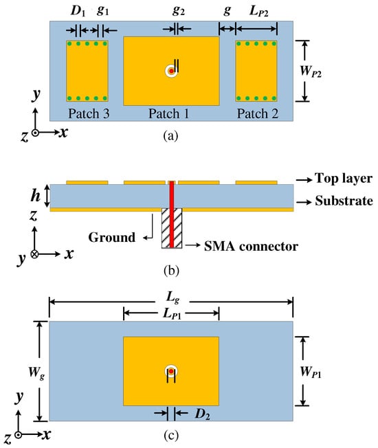
Figure 1.
The configurations of the proposed Ant. 1. (a) Top view, (b) cross-section view, (c) top view of the single patch antenna.
2.2. Antenna Operating Mechanism
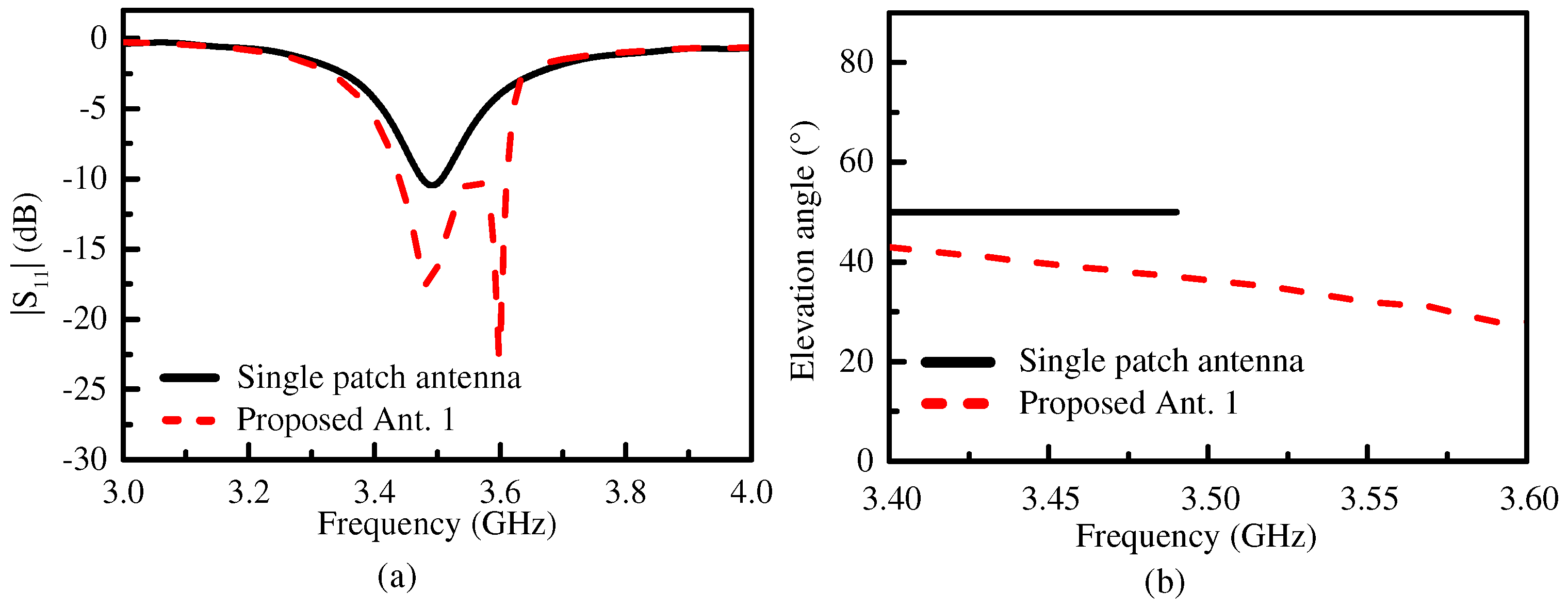
Figure 2a compares the simulated |S11| of the proposed Ant. 1 and the single patch antenna. The operating bandwidth (with |S11| < −10 dB) of the proposed Ant. 1 was about 4.8% (from 3.44 GHz to 3.61 GHz), which is significantly extended compared with the operating bandwidth of the single patch antenna (from 3.47 GHz to 3.51 GHz). From the simulation results, we can see that there were two reflection zeros of the proposed Ant. 1 at the frequencies of 3.49 GHz and 3.59 GHz, while the single patch antenna had only one reflection zero at 3.48 GHz. Figure 2b shows that the elevation angle of the proposed Ant. 1 ranged from ±40° to ±28° within the operating bandwidth, which is clearly lower than the 50° of the single patch antenna. The elevation angle of the single patch antenna remained unchanged within the operating bandwidth, and the elevation angle of the proposed Ant. 1 decreased with the frequency increase.
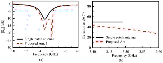
Figure 2.
The simulated (a) |S11| and (b) the elevation angles of the proposed Ant. 1 and the single patch antenna within their respective operating bandwidth.
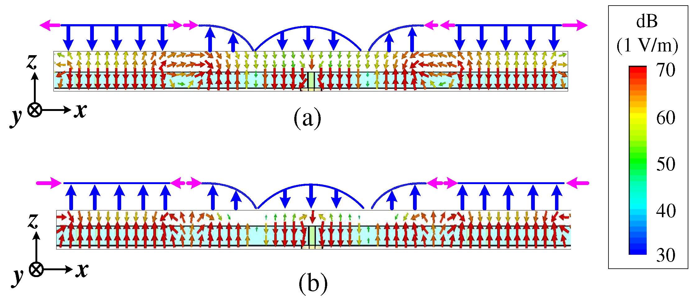
Figure 3 shows the simulated vector’s electric field distribution of the proposed Ant. 1. It is clear that the internal electric field distribution of Patch 1 was on TM20 mode: the electric field was a full-wave distribution in the x direction, while, in the y direction, the direction of the electric field was the same and the amplitude was equal. The internal electric field distribution of Patch 2 and Patch 3 was on TM01 mode, the direction of the electric field was the same and the amplitude was equal in the x direction, while the electric field exhibited a half-wave distribution in the y direction. The horizontal components of the electric field of the TM20 mode on both sides of Patch 1 had equal amplitudes and opposite directions, so the far-field radiation pattern was offset from the broadside but superimposed along the endfire direction, which can generate the symmetrical dual-beam radiation. The internal electric field of the TM01 mode was of equal amplitude and in the same direction, the horizontal electric field components on the left and right sides of Patch 2 and Patch 3 had equal amplitudes and a phase difference of 180°, which can maintain the bidirectional radiation of the proposed Ant. 1. Meanwhile, two reflection zeros were formed due to the coupling of the TM20 mode with the TM01 mode, a phenomenon which is consistent with the simulation results in Figure 2a. At the first reflection zero (Figure 3a), the electric field of the two modes was almost reversed (blue arrow), and the electric field amplitude of the TM01 mode was smaller than that of the TM20 mode. The direction of the horizontal components of the electric field near two adjacent resonators was similar (pink arrow). At the second reflection zero (Figure 3b), the electric field of the two modes was similar, and the electric field amplitude of the TM01 mode was equal to that of the TM20 mode. The direction of the horizontal components of the electric field near two adjacent resonators was reversed. The change of coupling with the frequency resulted in the change of the elevation angle, confirming the results in Figure 2b.
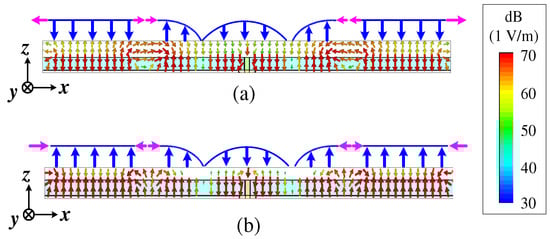
Figure 3.
The simulated vector’s electric field distribution of the proposed Ant. 1. (a) At the first reflection zero (at 3.49 GHz), (b) at the second reflection zero (at 3.59 GHz).
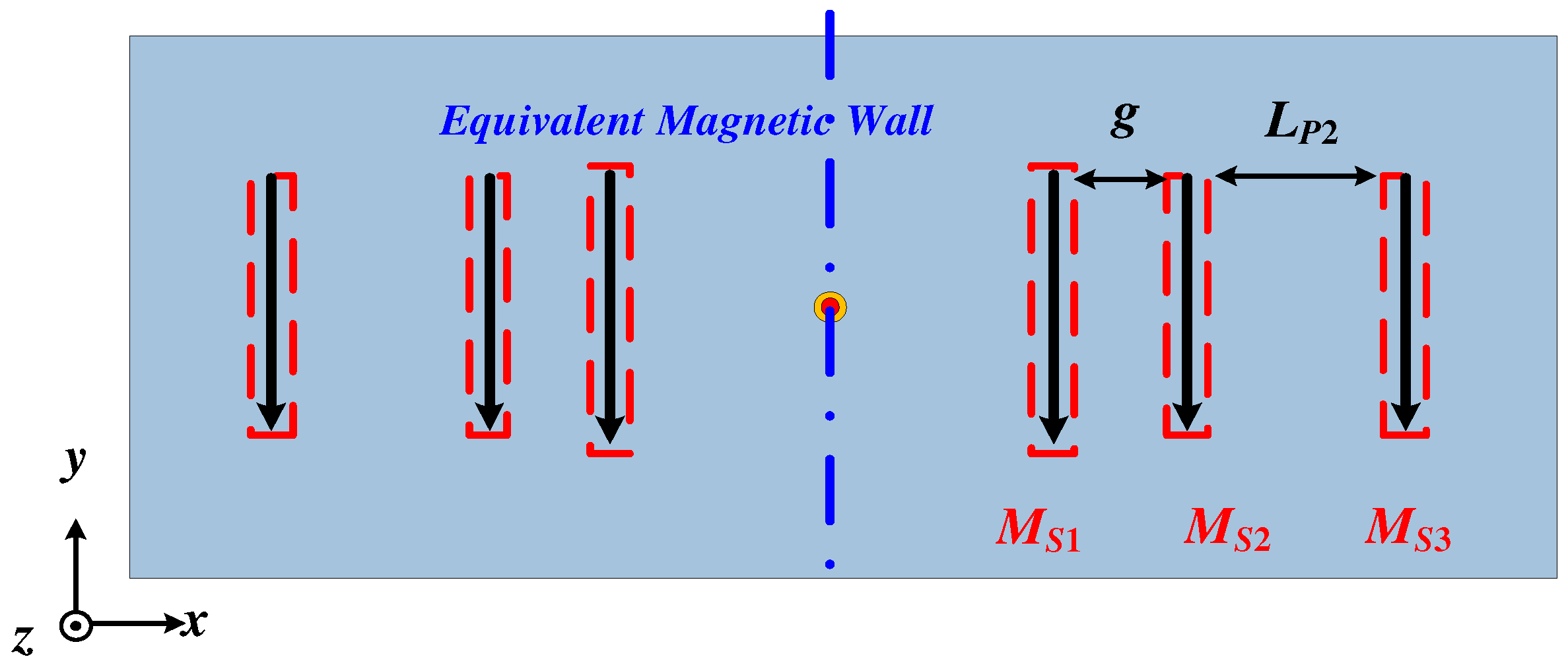
According to the antenna radiation theory [30], the radiation pattern of a patch antenna can be equivalent to the radiation superposition of the magnetic currents in two slots located along two radiation edges of the patch. Thus, the proposed Ant. 1 can be equivalent to six magnetic current sources, as shown in Figure 4. Meanwhile, the whole antenna is center-symmetric, and the central plane is equivalent to a magnetic wall, so that the far-field electric field of the right half part can be calculated using a three-element slots array, expressed as MS1, MS2, and MS3. The distances separating the three adjacent slots are g and LP2. Hence, the far-field electric field radiated by MS1, MS2, and MS3 can be expressed as:
where FE(φ) is the amplitude of the far-field electric field, E1ϕ, E2ϕ, E3ϕ are the far-field electric fields induced by MS1, MS2, and MS3, respectively, and φ is the beam tilt angle.
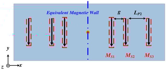
Figure 4.
The equivalent magnetic currents of the proposed Ant. 1.
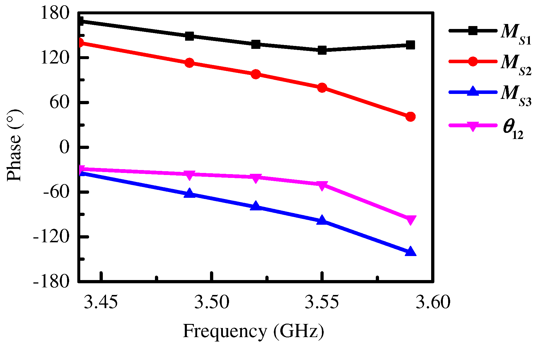
According to the analysis of the working modes of the proposed antenna, we know that Patch 2 operated on TM01 mode, so the magnetic currents MS2 and MS3 maintained the same amplitude and 180° phase difference. Figure 5 also gives the simulated phases of MS1, MS2, and MS3 within the operating bandwidth, from which we can see that the phase difference between MS2 and MS3 was close to 180°, that is:
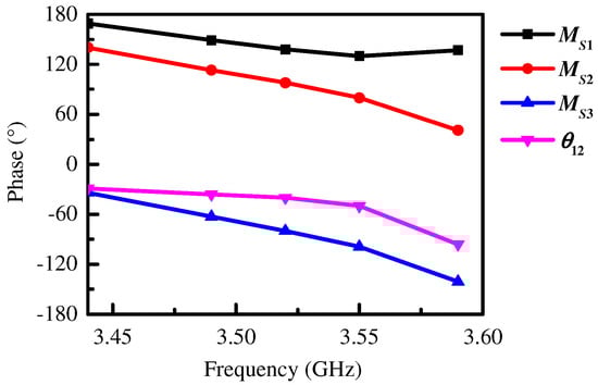
Figure 5.
The simulated phases of MS1, MS2, and MS3, and phase difference θ12 between MS2 and MS1.
Assuming that the ratio of the amplitudes between MS2 and MS1 is a1, and the phase difference between them is θ12:
Thus, the electric field strength in the far field of the three equivalent magnetic currents can be obtained as:
In the E-plane (θ = 90°), the far-field electric field of the right half antenna is:
From (5), we can conclude that the beam tilt angle (φ) is a function of g, LP2, a1, and θ12. Among them, a1 and θ12 are the key factors affecting radiation pattern, while the value of g and LP2 will influence a1 and θ12, but a1 has only a small effect on the beam angle. In this work, we mainly focused on the effect of θ12 on the elevation angle. When −180° < θ12 < 0°, the other parameters were fixed, with Patch 2 acting as a director. When 0° < θ12 < 180° and the other parameters were fixed, Patch 2 acted as a reflector. As the value of θ12 decreased, the radiation beam moved from a broadside direction to an endfire direction, meaning that the elevation angle was reduced.
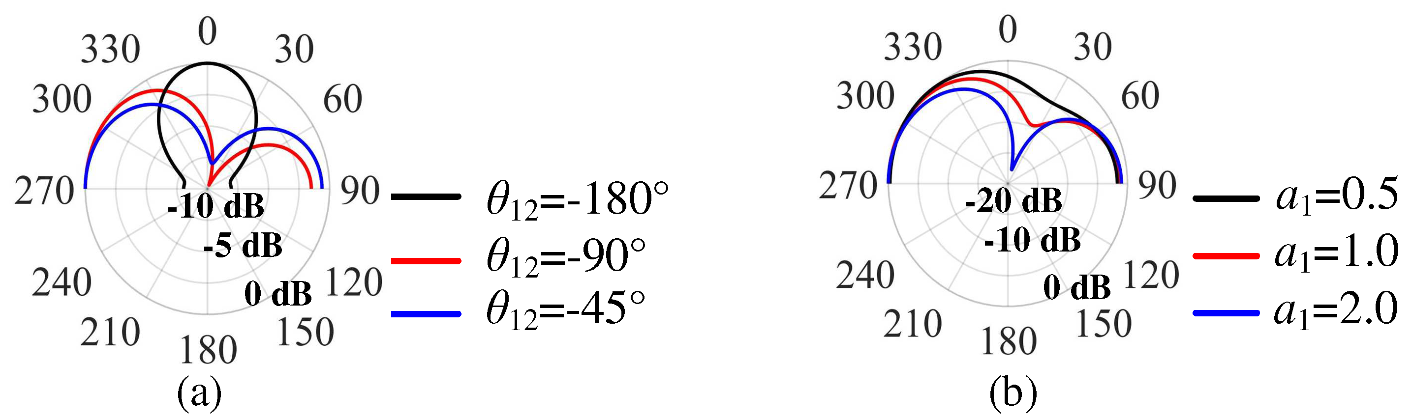
Figure 6 gives the calculated E-plane radiation patterns with different θ12 and a1 according to (5). Figure 6a illustrates the case of −180° < θ12 < 0°, with the radiation beam moving from a broadside direction to an endfire direction, indicating that Patch 2 acted as director. The elevation angle decreased with increasing θ12. The elevation angle remained almost unchanged when a1 increased from 0.5 to 2, as shown in Figure 6b.
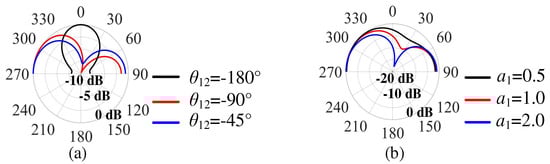
Figure 6.
The calculated E-plane radiation patterns (a) with different θ12, (b) with different a1.
The simulated phase difference θ12 between MS2 and MS1 is also given in Figure 5. Here, the phase of the equivalent magnetic current was calculated by the midpoint of the corresponding slot width in the simulation because the phase distribution along the slot width was uniform, as shown in Figure 7. We can see that the value of θ12 was in the range of −180° < θ12 < 0°, indicating that Patch 2 played the role of director. Similarly, we can conclude that Patch 3 also acted as a director, causing the dual beams of the proposed Ant. 1 to be tilted toward the endfire direction at the same time and the elevation angle of the proposed Ant. 1 to be reduced. Furthermore, the elevation angle was reduced in the operating bandwidth because the value of θ12 decreased with increasing frequency. The simulation results in Figure 2b are consistent with the above analysis.
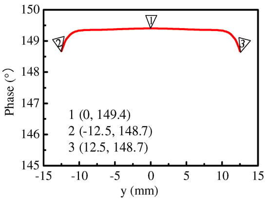
Figure 7.
The phase distribution along the slot width (MS1) at 3.49 GHz.
2.3. Parametric Analysis on LP2, WP2, and g
Subsequently, the key parameters that affect |S11| and the elevation angle of the proposed Ant. 1 were analyzed, such parameters mainly including the length of the shortened patch LP2, the width of the shortened patch WP2, and the distance between the shortened patch and the open patch g, as shown in Figure 8.
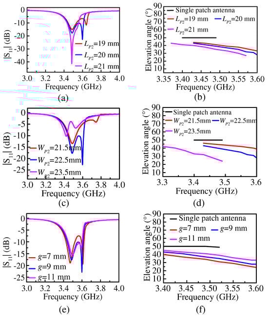
Figure 8.
(a) The simulated |S11| and (b) the elevation angle of the proposed Ant. 1 under different LP2. (c) The simulated |S11| and (d) the elevation angle of the proposed Ant. 1 under different WP2. (e) The simulated |S11| and (f) the elevation angle of the proposed Ant. 1 under different g.
From Figure 8a, we can see that the second reflection zero decreased with an increase in LP2. This is because the value of LP2 affected the resonant frequency of Patch 2. As the value of LP2 increased, the resonant frequency of Patch 2 decreased. When the value of LP2 varied from 19 mm to 21mm while keeping the other parameters fixed, the minimum elevation angle decreased from 32° to 27°, as shown in Figure 8b, and it gradually tilted away from the broadside direction toward the endfire direction. The reason is that the coupling of Patch 2 was enhanced with the increase in LP2. However, when the value of LP2 was too large, the second reflection zero moved closer to the first reflection zero, and the operating bandwidth of the proposed antenna became narrower. When the value of LP2 was too small, the distance between the two reflection zeros was large, with impedance mismatching somewhere in the operating bandwidth and a narrow operating bandwidth. Therefore, it is necessary to choose an appropriate value of LP2 to ensure a wide operating bandwidth while reducing the elevation angle. In this work, the value of LP2 was selected to be 20 mm based on the simulation results.
From Figure 8c, we can see that the second reflection zero decreased with an increase in WP2, because the value of WP2 affected the resonance frequency of Patch 2. As WP2 increased, the resonant frequency of Patch 2 decreased and the elevation angle decreased with the increase in WP2. As the value of WP2 increased from 21.5 mm to 23.5 mm while keeping the other parameters fixed, the minimum elevation angle decreased from 39° to 24°, as shown in Figure 8d. This is because the coupling of Patch 2 was enhanced with an increase in WP2. However, if the value of WP2 was too small, the distance between the two reflection zeros would be too large, splitting the operating bandwidth and reducing the matching bandwidth. If the value of WP2 was too large, the reflection performance of the proposed antenna would deteriorate sharply. Based on the aforementioned analysis, there was a tradeoff between the low elevation angle and a wide matching bandwidth. From the simulation results, we can see that a value of 22.5 mm was suitable for WP2.
The elevation angle decreased with a decrease in g, as shown in Figure 8f. As the value of g decreased from 11 mm to 7 mm while keeping the other parameters fixed, the minimum elevation angle decreased from 33° to 25°. This is because the coupling between Patch 1 and Patch 2 was stronger with a decrease in g. Meanwhile, the frequency spacing between the two resonant points increased with a decrease in g, resulting in deteriorated impedance matching, as shown in Figure 8e. Therefore, the value of g should be selected after considering the low elevation angle and good impedance matching bandwidth. After comprehensive consideration, the value of g was selected to be 9 mm.
2.4. Research on the Bidirectional Quasi-Endfire Patch Antenna with Multiple Shortened Patches
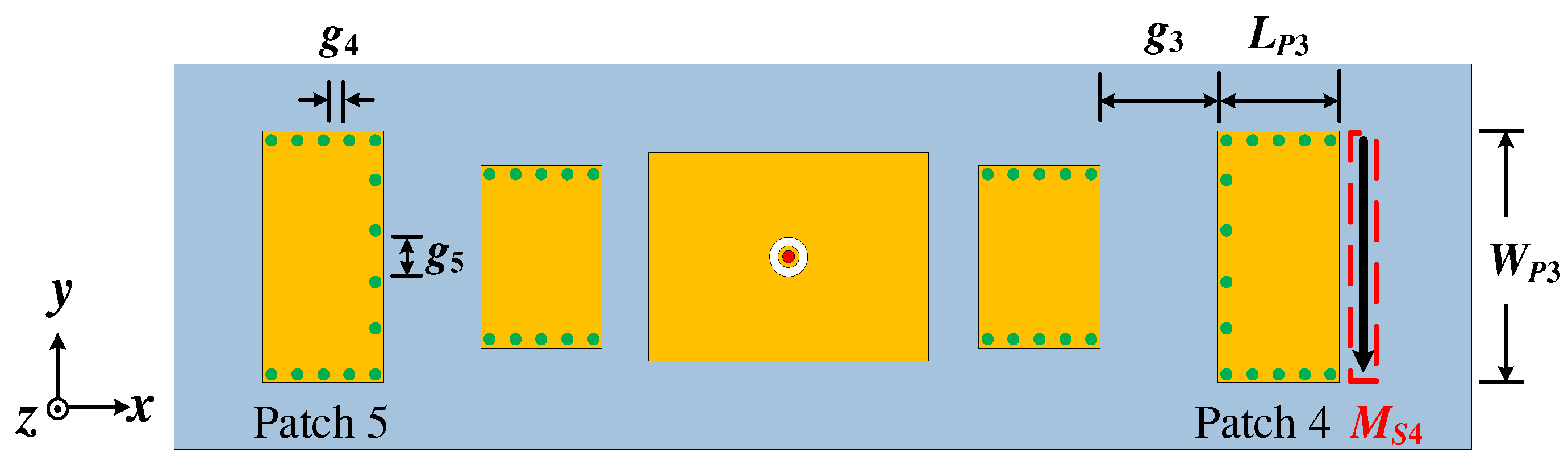
Through the above research, the proposed Ant. 1 loaded with a pair of shortened patches on both sides, equivalent to two magnetic current sources on both sides, was shown to reduce the elevation angle. Based on this, we researched the patch antenna loading with three equivalent magnetic current sources on both sides to further reduce the elevation angle. A patch antenna (the proposed Ant. 2) loaded with an extra pair of shortened patches (Patch 4 and Patch 5) with three edges operating on TM01 mode was proposed, where Patch 4 or Patch 5 were equivalent to one magnetic current source. So, the calculation for the size of Patch 4/Patch 5 is like that of the half-mode SIW [31]. The configuration of the proposed Ant. 2 is given in Figure 9. Similarly, the patch resonator that can provide two or three magnetic currents can also be used as a director; however, this is not described in detail in this work.
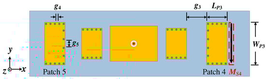
Figure 9.
The configuration of the proposed Ant. 2.
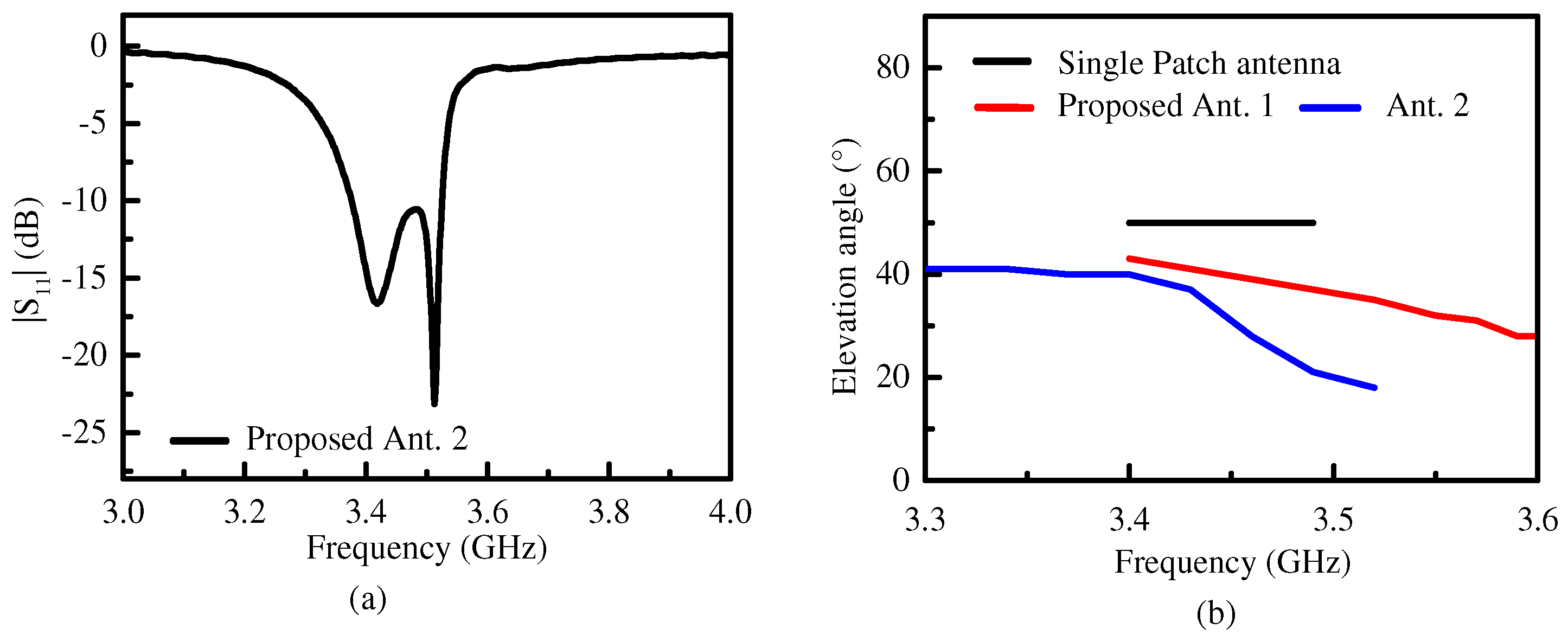
Figure 10a is the simulated |S11| of the proposed Ant. 2. There are two reflection zeros and the −10 dB impedance matching bandwidth ranged from 3.37 GHz to 3.52 GHz and corresponded to 4.3% in fraction. As shown in Figure 10b, the lowest elevation angle of 19° was lower than that of the proposed Ant. 1. The elevation angle gradually decreased from 40° to 19° as the frequency increased. This is because the coupling of MS3 with MS4 in relation to the proposed Ant. 2 increased with increasing frequency, so the elevation angle was further reduced, although the overall size was larger than that of the proposed Ant. 1.
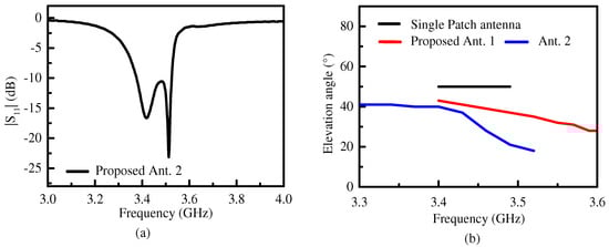
Figure 10.
(a) The simulated |S11| of the proposed Ant. 2. (b) Elevation angles of the single-patch antenna, the proposed Ant. 1, and the proposed Ant. 2 in their respective operating bandwidths.
3. Results and Discussion
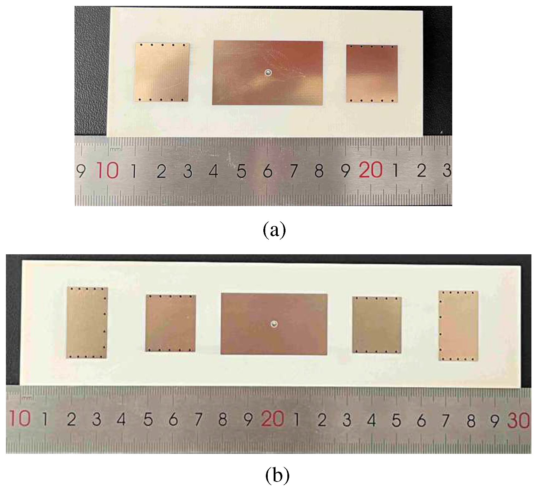
In order to verify the radiation characteristics of the proposed bidirectional quasi-endfire patch antenna, based on the above analysis, two prototypes of the two proposed antennas were designed and measured, as shown in Figure 11. The detailed dimensions of the proposed Ant. 1 were: Lg = 120, Wg = 50, LP1 = 42, WP1 = 25, LP2 = 20, WP2 = 22.5, D1 = 0.8, g = 9, g1 = 3.2, D2 = 2.1, g2 = 0.3, and h = 3.148, where the unit is mm. The detailed dimensions of the proposed Ant. 2 were: Lg = 200, Wg = 50, LP1 = 43, WP1 = 25, LP2 = 20, WP2 = 23, LP3 = 16, WP3 = 28.5, g = 10, D1 = 0.8, g1 = 3.2, D2 = 2.1, g2 = 0.3, g3 = 15, g4 = 2.2, and g5 = 6.2, where the unit is mm.

Figure 11.
The prototype of (a) the proposed Ant. 1 and (b) the proposed Ant. 2.
The S-parameter was measured using the Keysight N5230C vector network analyzer (Keysight Technologies, Santa Clara, CA, USA). The radiation patterns and the beam elevation angles were measured inside an anechoic chamber with a far-field antenna measurement system. Figure 12 shows the simulated and measured |S11| of two proposed antennas. The −10 dB impedance matching bandwidth of the proposed Ant. 1 was about 4.3% (3.45–3.6 GHz), as shown in Figure 12a, and the peak gain of the proposed Ant. 1 was about 5.2 dBi. The −10 dB impedance matching bandwidth of the proposed Ant. 2 was about 3.2% (3.4–3.51 GHz), as shown in Figure 12b, and the peak gain of the proposed Ant. 2 was 6.0 dBi. The small discrepancy between the simulated and measured results was due to the manufacturing tolerance and the measurement error.
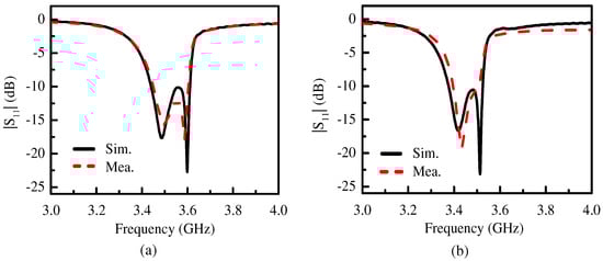
Figure 12.
The simulated and measured |S11| of (a) the proposed Ant. 1 and (b) the proposed Ant. 2.
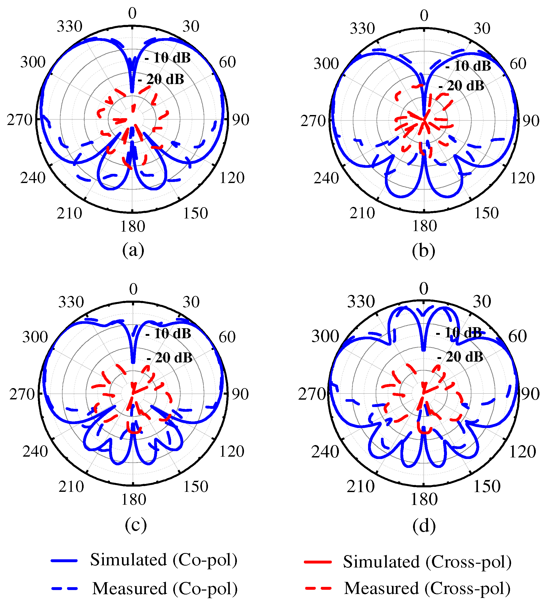
Figure 13 illustrates the simulated and measured radiation patterns of two proposed antennas on the E-plane at two reflection zeros. For the proposed Ant. 1, the elevation angles at two reflection zeros were ±40° and ±28°, as shown in Figure 13a,b. For the proposed Ant. 2, the elevation angles at two reflection zeros were ±40° and ±19°, as shown in Figure 13c,d. The measured cross polarization levels were both below −20 dB.
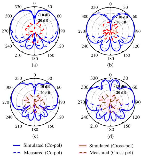
Figure 13.
The simulated and measured radiation patterns on the E-plane of the two proposed antennas at two reflection zeros. (a) The proposed Ant. 1 at 3.49 GHz, (b) the proposed Ant. 1 at 3.59 GHz, (c) the proposed Ant. 2 at 3.42 GHz, and (d) the proposed Ant. 2 at 3.51 GHz.
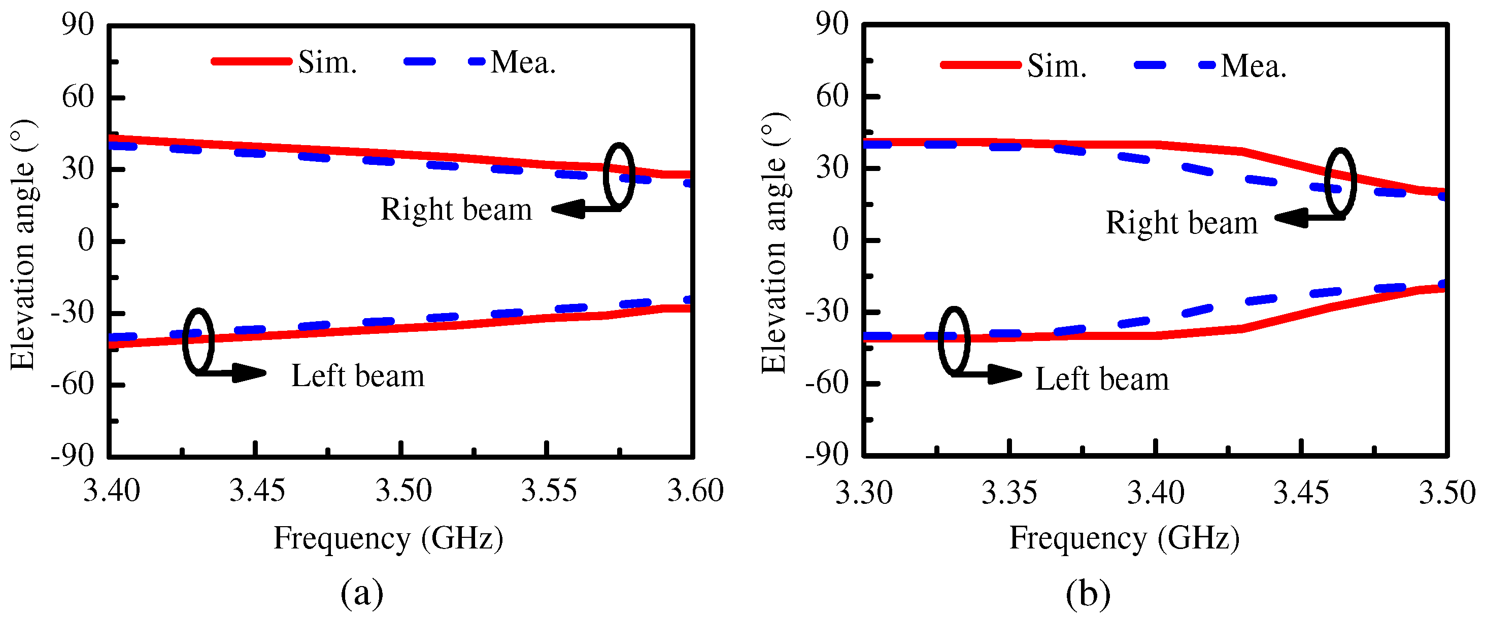
Figure 14 presents the simulated and measured elevation angles within the operating bandwidth for the two proposed antennas. From Figure 14, it can be seen that the elevation angle of the proposed Ant. 1 ranged from ±40° to ±28° in the operating bandwidth and the elevation angle of the proposed Ant. 2 ranged from ±40° to ±19° in the operating bandwidth. The elevation angle decreased with increasing frequency. The measured results are in agreement with the simulated outputs.
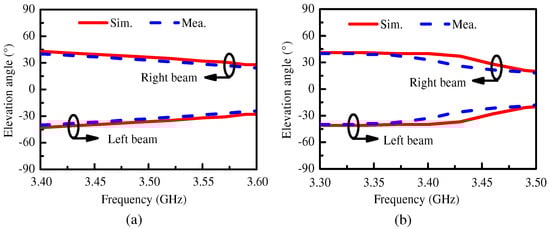
Figure 14.
The simulated and measured elevation angles within the operating bandwidth of (a) the proposed Ant. 1 and (b) the proposed Ant. 2.
Table 1 provides the comparison between the proposed bidirectional quasi-endfire patch antennas and some reported designs. Compared with these designs, the proposed antennas attained the lowest elevation angle while retaining a compact structure. The level of manufacturing complexity for the antennas was divided into high (H), medium (M), and low (L), determined by considering the layers and the structure complexity of the designed antenna in the manufacturing process.

Table 1.
Performance summary of the proposed antennas and state-of-the art designs.
4. Conclusions
In this paper, a bidirectional quasi-endfire patch antenna with a low elevation angle is proposed. By controlling the mutual coupling between the TM01 mode and the TM20 mode, the phase distribution on the radiation edges met the requirement of bidirectional quasi-endfire radiation and attained a low elevation angle of ±28°. Furthermore, the lowest elevation angle of ±19° was obtained by using two pair of shortened patches to improve the control ability of the beam angle. Compared with the reported patch antennas with dual beams, the proposed design can attain the lowest elevation angle, which is suitable for wireless communication systems that are airborne, shipborne, and vehicle-based.
Author Contributions
Conceptualization, J.S.; methodology, J.S. and K.X.; software, Z.Z. and G.L.; validation, J.S., K.X. and R.J.; formal analysis, J.S.; investigation, G.L. and Z.Z.; resources, J.S., K.X. and R.J.; data curation, G.L. and R.J.; writing—original draft preparation, Z.Z. and R.J.; writing—review and editing, J.S. and R.J.; visualization, R.J.; supervision, J.S.; project administration, J.S. and R.J.; funding acquisition, J.S., K.X. and R.J. All authors have read and agreed to the published version of the manuscript.
Funding
This research was funded by the National Natural Science Foundation of China (No. 62201291, No. 62201292, and No. 62301285), Key Research and Development Program of Jiangsu Province of China (No. BE2021013-1), Nantong Science and Technology Plan Project (No. JB2021006), Natural Science Foundation of Jiangsu Province (No. BK20200962), Natural Science Research Project of Jiangsu Higher Education Institutions (No. 23KJB510024, No. 22KJB140004 and No. 21KJD430001).
Data Availability Statement
The data presented in this study are available upon request from the corresponding author.
Conflicts of Interest
The authors declare no conflicts of interest.
References
- Ye, M.; Li, X.R.; Chu, Q.X. Single-layer single-fed endfire antenna with bidirectional circularly polarized radiation of the same sense. IEEE Antennas Wirel. Propag. Lett. 2017, 16, 621–624. [Google Scholar] [CrossRef]
- Hu, J.; Hao, Z.C.; Fan, K.; Guo, Z. A bidirectional same sense circularly polarized endfire antenna array with polarization reconfigurability. IEEE Trans. Antennas Propag. 2019, 67, 7150–7155. [Google Scholar] [CrossRef]
- Liang, Z.; Lv, S.; Li, Y.; Liu, J.; Long, Y. Compact folded slot antenna and its endfire arrays with high gain and vertical polarization. IEEE Antennas Wirel. Propag. Lett. 2020, 19, 786–790. [Google Scholar] [CrossRef]
- Yan, Y.D.; Jiao, Y.C.; Zhang, C. A circularly polarized-reconfigurable planar end-fire antenna with bidirectional radiation of same sense and wide beamwidth. Int. J. RF Microw. Comput. Eng. 2020, 30, e22469. [Google Scholar] [CrossRef]
- Ke, Y.H.; Yang, L.L.; Chen, J.X. Design of switchable dual-Balun feeding structure for pattern-reconfigurable endfire antenna. IEEE Antennas Wirel. Propag. Lett. 2021, 20, 1463–1467. [Google Scholar] [CrossRef]
- Huang, Y.X.; Yan, Y.X.; Yu, W.; Qin, W.; Chen, J.X. Integration design of millimeter-wave bidirectional endfire filtenna array fed by SIW filtering power divider. IEEE Antennas Wirel. Propag. Lett. 2022, 21, 1457–1461. [Google Scholar] [CrossRef]
- Chen, C.; Guo, Y.; Wang, H. Wideband symmetrical cross-shaped probe dual-beam microstrip patch antenna. IEEE Antennas Wirel. Propag. Lett. 2015, 14, 622–625. [Google Scholar] [CrossRef]
- Li, J.F.; Chen, Z.N.; Wu, D.L.; Zhang, G.; Wu, Y.J. Dual-beam filtering patch antennas for wireless communication application. IEEE Trans. Antennas Propag. 2018, 66, 3730–3734. [Google Scholar] [CrossRef]
- Li, J.F.; Mao, C.H.; Wu, D.L.; Ye, L.H.; Zhang, G. A dual-beam wideband filtering patch antenna with absorptive band-edge radiation nulls. IEEE Trans. Antennas Propag. 2021, 69, 8926–8931. [Google Scholar] [CrossRef]
- Khidre, A.; Lee, K.F.; Elsherbeni, A.Z.; Yang, F. Wide band dual-beam U-slot microstrip antenna. IEEE Trans. Antennas Propag. 2013, 61, 1415–1418. [Google Scholar] [CrossRef]
- Liu, S.; Qi, S.S.; Wu, W.; Fang, D.G. Single-feed dual-band single/dual-beam U-slot antenna for wireless communication application. IEEE Trans. Antennas Propag. 2015, 63, 3759–3764. [Google Scholar] [CrossRef]
- Lu, H.; Liu, F.; Liu, Y.; Huang, S.; Principle, A.O. Single-layer single-patch wideband dual-beam E-shaped patch antenna. In Proceedings of the 2017 IEEE 5th International Symposium on Electromagnetic Compatibility (EMC-Beijing), Beijing, China, 28–31 October 2017. [Google Scholar]
- Yang, G.; Li, J.; Xu, R.; Yang, J.; Qi, Y. Dual-band single/dual-beam slot patch antenna. In Proceedings of the 2018 IEEE International Symposium on Antennas and Propagation & USNC/URSI National Radio Science Meeting, Boston, MA, USA, 8–13 July 2018. [Google Scholar]
- Kumari, P.; Das, S. A MIMO antenna system using self-decoupled EMSIW dual-beam antenna elements. IEEE Access 2022, 10, 1339–1345. [Google Scholar] [CrossRef]
- Ellis, M.S.; Nourinia, J.; Ghobadi, C.; Hosseini, K.; Alizadeh, F.; Mohammadi, B. Compact wideband printed antenna with circularly polarized tilted beam radiation using a quasi-radiator. AEU Int. J. Electron. Commun. 2023, 171, 154883. [Google Scholar] [CrossRef]
- Wang, R.; Wang, B.Z.; Ding, X. Broadband quasi-bidirectional antenna with vertical polarization. IEEE Antennas Wirel. Propag. Lett. 2018, 17, 2232–2236. [Google Scholar] [CrossRef]
- Shukla, P.K.; Sikandar; Tripathi, V.S.; Sharma, A. Dual band circularly polarized partially reflecting surface-loaded dielectric resonator-based MIMO antenna for mm-wave 5G applications. Int. J. Microw. Wirel. Technol. 2024, 1–10. [Google Scholar] [CrossRef]
- Zhu, B.; Yang, D.; Pan, J.; Chen, Y.; Liu, S. A low-profile metasurface-inspired antenna with tilted beam radiation. IEEE Antennas Wirel. Propag. Lett. 2023, 22, 1803–1807. [Google Scholar] [CrossRef]
- Huang, J. Planar microstrip Yagi array antenna. IEEE Antennas Propag. Soc. AP-S Int. Symp. 1989, 2, 894–897. [Google Scholar]
- Liu, J.; Xue, Q. Microstrip magnetic dipole Yagi array antenna with endfire radiation and vertical polarization. IEEE Trans. Antennas Propag. 2013, 61, 1140–1147. [Google Scholar] [CrossRef]
- DeJean, G.R.; Tentzeris, M.M. A new high-gain microstrip Yagi array antenna with a high front-to-back (F/B) ratio for WLAN and millimeter-wave applications. IEEE Trans. Antennas Propag. 2007, 55, 298–304. [Google Scholar] [CrossRef]
- DeJean, G.R.; Thai, T.T.; Nikolaou, S.; Tentzeris, M.M. Design and analysis of microstrip bi-Yagi and quad-Yagi antenna arrays for WLAN applications. IEEE Antennas Wirel. Propag. Lett. 2007, 6, 244–248. [Google Scholar] [CrossRef]
- Thai, T.T.; DeJean, G.R.; Tentzeris, M.M. Design and development of a novel compact soft-surface structure for the front-to-back ratio improvement and size reduction of a microstrip Yagi Array Antenna. IEEE Antennas Wirel. Propag. Lett. 2008, 7, 369–373. [Google Scholar] [CrossRef]
- Shi, J.; Zhu, L.; Liu, N.; Wu, W. A novel microstrip Yagi antenna with an improved end-fire radiation pattern under operation of the TM20 mode. Int. J. RF Microw. Comput. Eng. 2019, 29, e21789. [Google Scholar]
- Shi, J.; Zhu, L.; Liu, N.W.; Wu, W. A microstrip Yagi antenna with an enlarged beam tilt angle via a slot-loaded patch reflector and pin-loaded patch directors. IEEE Antennas Wirel. Propag. Lett. 2019, 18, 679–683. [Google Scholar] [CrossRef]
- Guo, E.; Liu, J.; Long, Y. A mode-superposed microstrip patch antenna and its Yagi array with high front-to-back ratio. IEEE Trans. Antennas Propag. 2017, 65, 7328–7333. [Google Scholar] [CrossRef]
- Dutta, R.K.; Jaiswal, R.K.; Saikia, M.; Srivastava, K.V. A two-stage beamforming antenna using Butler matrix and reconfigurable frequency selective surface for wide angle beam tilting. IEEE Antennas Wirel. Propag. Lett. 2023, 22, 2342–2346. [Google Scholar] [CrossRef]
- Wang, P.; Wu, Q.; He, R.; Shao, Y. Design of low profile and wideband end-fire antenna using metasurface. IEEE Access 2020, 8, 35752–35758. [Google Scholar] [CrossRef]
- Ashraf, M.; Jamil, K.; Telba, A.; Alzabidi, M.; Sebak, A. Design and development of a wideband planar yagi antenna using tightly coupled directive element. Micromachines 2020, 11, 975. [Google Scholar] [CrossRef]
- Balanis, C. Antenna Theory: Analysis and Design, 3rd ed.; Wiley: Hoboken, NJ, USA, 2005. [Google Scholar]
- Cassivi, Y.; Perregrini, L.; Arcioni, P.; Bressan, M.; Wu, K.; Conciauro, G. Dispersion characteristics of substrate integrated rectangular waveguide. IEEE Microw. Wirel. Compon. Lett. 2002, 12, 333–335. [Google Scholar] [CrossRef]


Disclaimer/Publisher’s Note: The statements, opinions and data contained in all publications are solely those of the individual author(s) and contributor(s) and not of MDPI and/or the editor(s). MDPI and/or the editor(s) disclaim responsibility for any injury to people or property resulting from any ideas, methods, instructions or products referred to in the content. |
© 2024 by the authors. Licensee MDPI, Basel, Switzerland. This article is an open access article distributed under the terms and conditions of the Creative Commons Attribution (CC BY) license (https://creativecommons.org/licenses/by/4.0/).