1. Introduction
Deep microdrilling is a very complex manufacturing process, typically employed when there is a need for precise control over hole diameter, coupled with a requirement for excellent straightness and surface finish. It is usually referred to as deep drilling when the hole depth
D is 10 times larger than the nominal hole diameter
d [
1,
2]. Therefore, the aspect ratio (AR)
D/d > 10 is defined. Here, limited heat dissipation, intricate chip formation, and high trust force values are attributable to the depth of the cutting zone within the workpiece [
3,
4]. These phenomena are further emphasized in the micro domain by the small size of the tools, whose cutting edges have a radius comparable to the grain size of the material being cut, thus, size effects occur [
5]. Microdrills with a higher AR have a higher ratio of flute length to drill bit diameter. This contributes to lower rigidity and a higher risk of bending fracture [
6]. In addition, this micromanufacturing process is subject to various constraints, including susceptibility to vibration and rapid deterioration of cutting tools, requiring frequent tool changes to reduce errors in straightness, roundness, and cylindricity of microholes [
5,
7,
8]. For this reason, in areas such as aerospace or biomedicine, where deep microdrilling is widely used for its precision, measuring the diameter and depth of microholes and monitoring their internal geometry quality is essential. However, conventional measuring tools may have limitations in reaching the bottom of these holes or providing accurate measurements, causing uncertainties in hole quality assessment when high ARs take place. In fact, as depth increases, maintaining the diameter accuracy over the entire length of the hole becomes more difficult. Typically, destructive methods are used to evaluate the internal shape of microholes, which includes cutting cross-sections of holes and/or creating plastic replicas to reproduce the microholes [
9]. In fact, in these cases, conventional coordinate measuring machines (CMMs) and vision-based systems are unable to perform shape measurements on deep microholes [
10,
11]. For example, in the study conducted by Diver et al. [
12], the quality of reverse tapered microholes made by means of electrical discharge machining is examined using a new 3D imprint technique. This involved the use of hole impressions, and thus, sectioning the samples.
In light of this, the need to monitor the process in such a way as to ensure maximum accuracy in microcomponents without the need to section the machined parts arises. Generally, monitoring the micromilling or microdrilling process is critical to obtaining accurate parts. This process provides insight into the cutting mechanism and the occurring phenomena such as chip formation, vibration, and tool wear [
13,
14,
15,
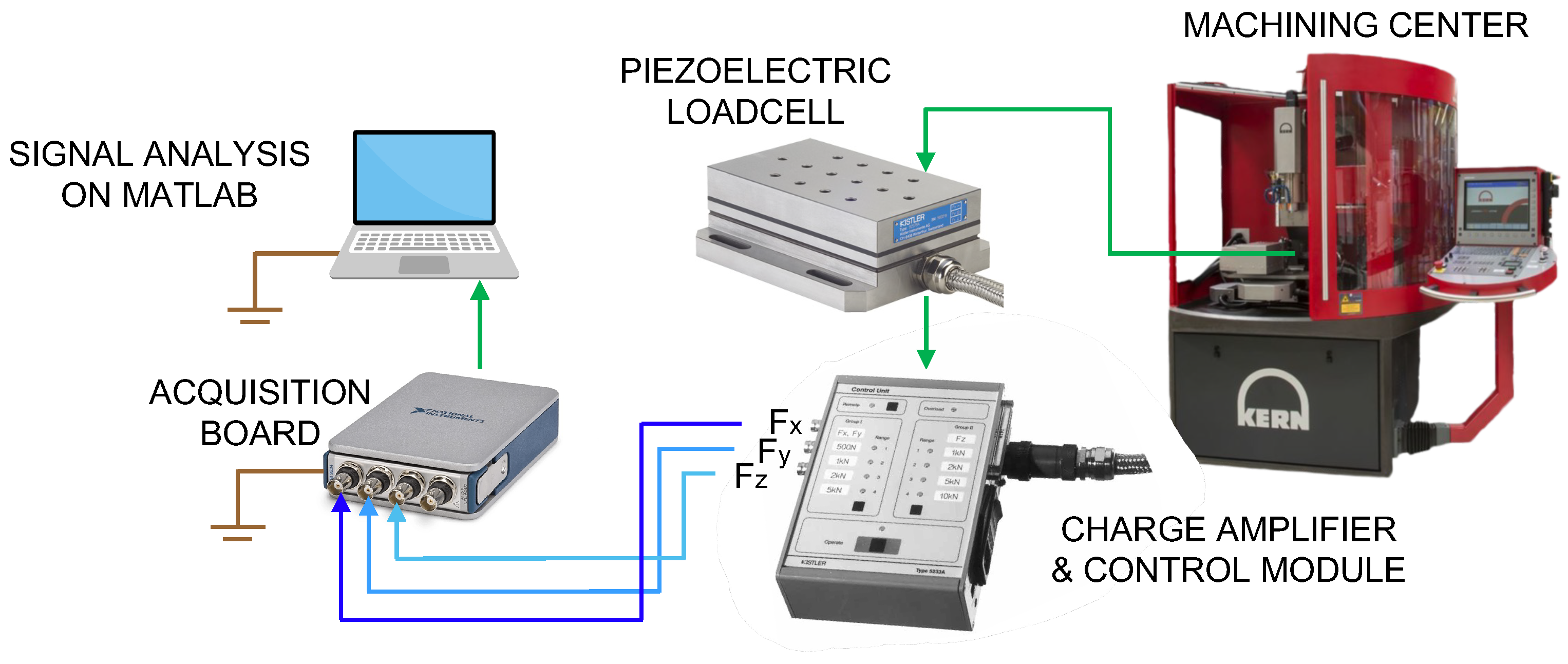
16]. Monitoring can involve the use of accelerometers, force or torque sensors, and current sensors. The data obtained, therefore, can be used as a diagnostic tool during machining [
17]. Thus, although continuous monitoring and control of the drilling process is essential to maintain the desired quality, real-time monitoring of deep-drilling microholes can be difficult. Implementing effective control systems is crucial to detect deviations and adjust process parameters accordingly. The relationship between cutting forces during deep microdrilling and hole morphology could provide insight into material removal mechanisms and challenges associated with the microscale [
18,
19]. The interaction between the cutting tool and the workpiece provides information about the cutting mechanism, specific interaction with the tool, and machine and tool conditions (such as wear, geometric runout, and vibration). The modulus and directions of the x- and y-components of the cutting force may contain relevant data on runout, consequently, the possible presence of geometric errors can be detected. This information is a valuable resource for the development and implementation of monitoring and diagnostic techniques in the machining process, especially when the small size does not allow the use of contact measurements. Kim et al. [
20] developed a method to improve the durability of microdrills in deep drilling on steel. The tests showed that the tool breakage event was preceded by a gradual increase in thrust force, spindle speed harmonic component and frequency content amplitudes in the 0–100 Hz range. Monitoring parameters of the process were finally chosen as the slope of the average thrust force signal, the peak-to-valley value of low-pass and high-pass filtered thrust forces.
An experimental campaign to study the effect of feed and cutting speed on cutting force components and hole quality in carbon fiber reinforced plastic composite (CFRP) material is described in the study conducted by Anand et al. [
21]. From this type of approach, it became possible to derive fundamental information for obtaining good hole quality in CFRP materials. It was observed that the cutting forces and hole quality are influenced by size effects in microdrilling. Specifically, the lowest cutting forces and the lowest hole quality error were obtained with feed close to the tool cutting edge radius, contrary to what was expected.
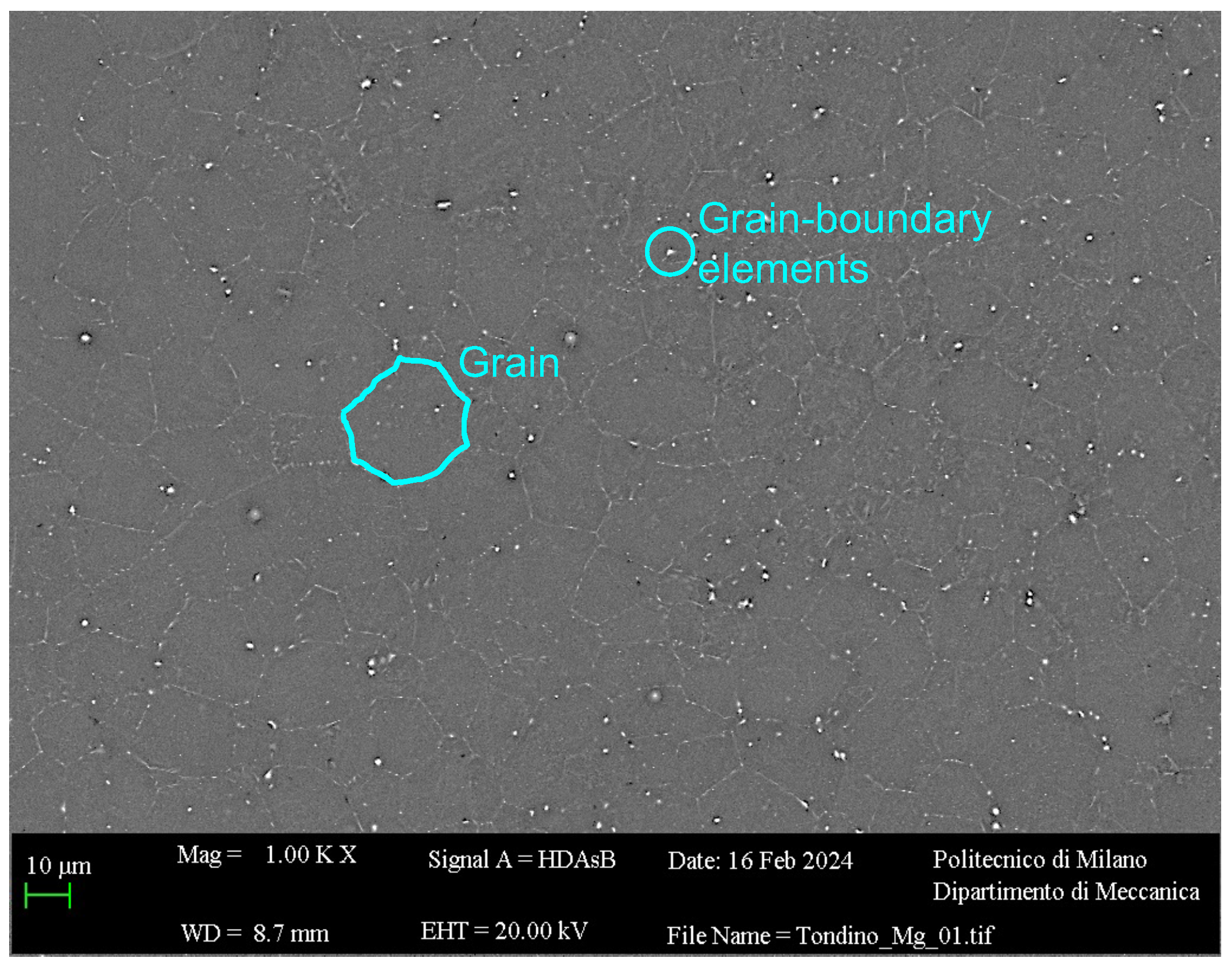
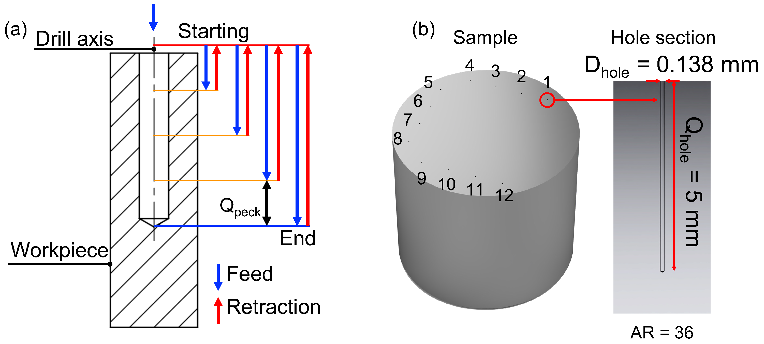
In light of what is present in the state of the art, this article reports a study performed on a microdrilling process on pure magnesium using a 0.138 mm diameter drill bit to achieve an AR equal to 36. Microdrilling experiments were performed to study the effect of feed per tooth and cutting speed on cutting forces, particularly thrust force, to support the study on hole quality as a function of cutting parameters. Hole quality was evaluated in terms of burr height, entrance diameter, and inner diameter.
The choice of magnesium as the material for this experimental study is well justified, especially in the biomedical field, where implantable devices must function for a limited period. Corrosion within body fluids allows the device to dissolve completely once its function is achieved, eliminating the necessity for surgical removal. Indeed, being biocompatible and biodegradable, this material is very suitable for the development of (i) drug delivery devices, (ii) needles, and (iii) implants for orthopedic applications [
22,
23,
24,
25]. The goal of this work is to bring innovative results to the state of the art on magnesium deep microdrilling, leading to a better understanding of the mechanisms of material removal in a difficult-to-monitor process. In fact, there are no studies in which the chip removal mechanism of pure magnesium with sub-millimeter diameter tools with such high AR is investigated. The study conducted by Sun et al. [
26], for example, proposes an experimental campaign on magnesium using drills of 1 mm in diameter and 9.5 mm in length (AR = 9.5), by drilling holes 4 mm deep. In the study conducted previously by the same authors of this paper [
27], the effect of cutting parameters on the quality of holes with a diameter 0.200 mm and depth about 4 mm (AR = 20) was investigated. In the present study, it is intended to increase the aspect ratio by almost two times, decreasing the tool diameter by 31%, and increasing the hole depth by 25%. This makes machining more risky due to (i) lower tool rigidity [
6], (ii) phenomena associated with microscaling such as minimum chip thickness [
5,
28], and (iii) greater difficulty in chip evacuation from hole depth [
3]. In addition, the analysis of the forces developed during the process and the analysis of the internal geometry of the hole are introduced.
4. Discussion
In light of the limited literature on deep-hole microdrilling of magnesium, an investigation of the effect of feed per tooth and cutting speed on hole quality and thrust force was carried out in this study to obtain holes with a diameter equal to 0.138 mm and very high AR equal to about 36 on a pure Mg sample. As performance indexes for the evaluation, the maximum and average thrust force, and , respectively, were analyzed. Similarly, an investigation of hole quality in terms of burr height Hburr, entrance diameter Dentr, and diameter along the axis of the hole was conducted.
Concerning the
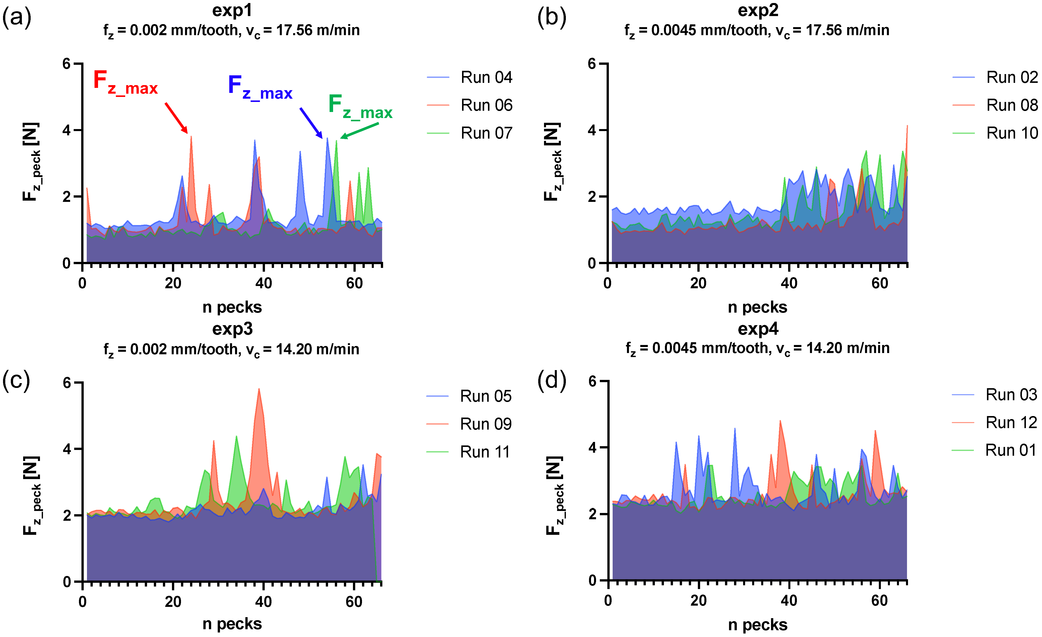
, the maximum thrust force for each run, no statistically relevant dependence with the factors was revealed from the TWA. This could be related to the nature of
. Indeed,
Figure 14 shows variability of the peak values
with the peck number. It can be assumed that the significant variation in forces across consecutive drilling cycles indicates that the chip formation and motion within the flutes is a stochastic process [
37]:
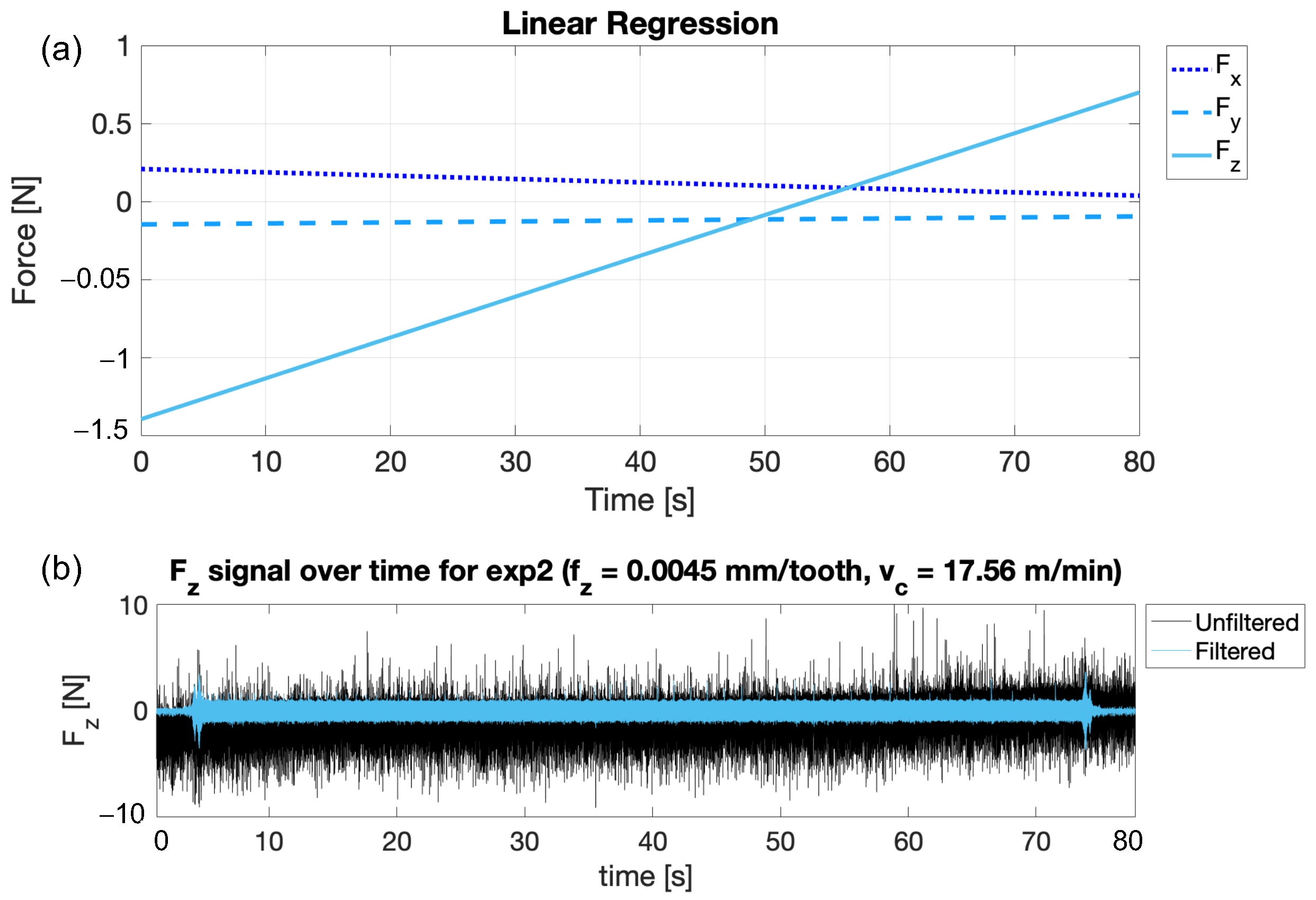
depends on random factors, such as the chip friction on the flute and hole wall and local lubrication conditions. The twist drill often fails to properly extract all the chips formed in the cutting area. As the chip clogs the hole and the drill is ready to start a new peck, more material is present than expected, causing a higher solicitation at the twist drill tip. Regarding the stability of the cut during the drilling operation, a few trends emerged. It is clear that exp2 (
= 0.0045 mm/tooth,
= 17.56 m/min) presents the most stable cut with an increase in the thrust force peaks in the last part of the drilling operation where the hole is deeper and consequently the chip evacuation is hindered (
Figure 14b). The reason behind the stability of exp2 might reside in the combination of the thermal softening induced by the high levels of cutting speed and the quick chip extraction caused by the feed rate
defined in Equation (
2).
On the contrary, exp4 (
= 0.0045 mm/tooth,
= 14.20 m/min) presents the most unstable cut with an increase in the thrust force peaks early in the operation (
Figure 14d). To have a better understanding of how the combination of the used parameters affects the maximum thrust force, further investigation would be necessary. For instance, a lower peck depth could be applied to the second half of the hole, in order to facilitate chip evacuation reducing the volume of the produced chip. Conversely, reducing the pecking depth could lead to lower drill bit stability, worse surface finish, and higher diametral, roundness, and cylindricity errors because of a higher number of tool re-engagements [
38].
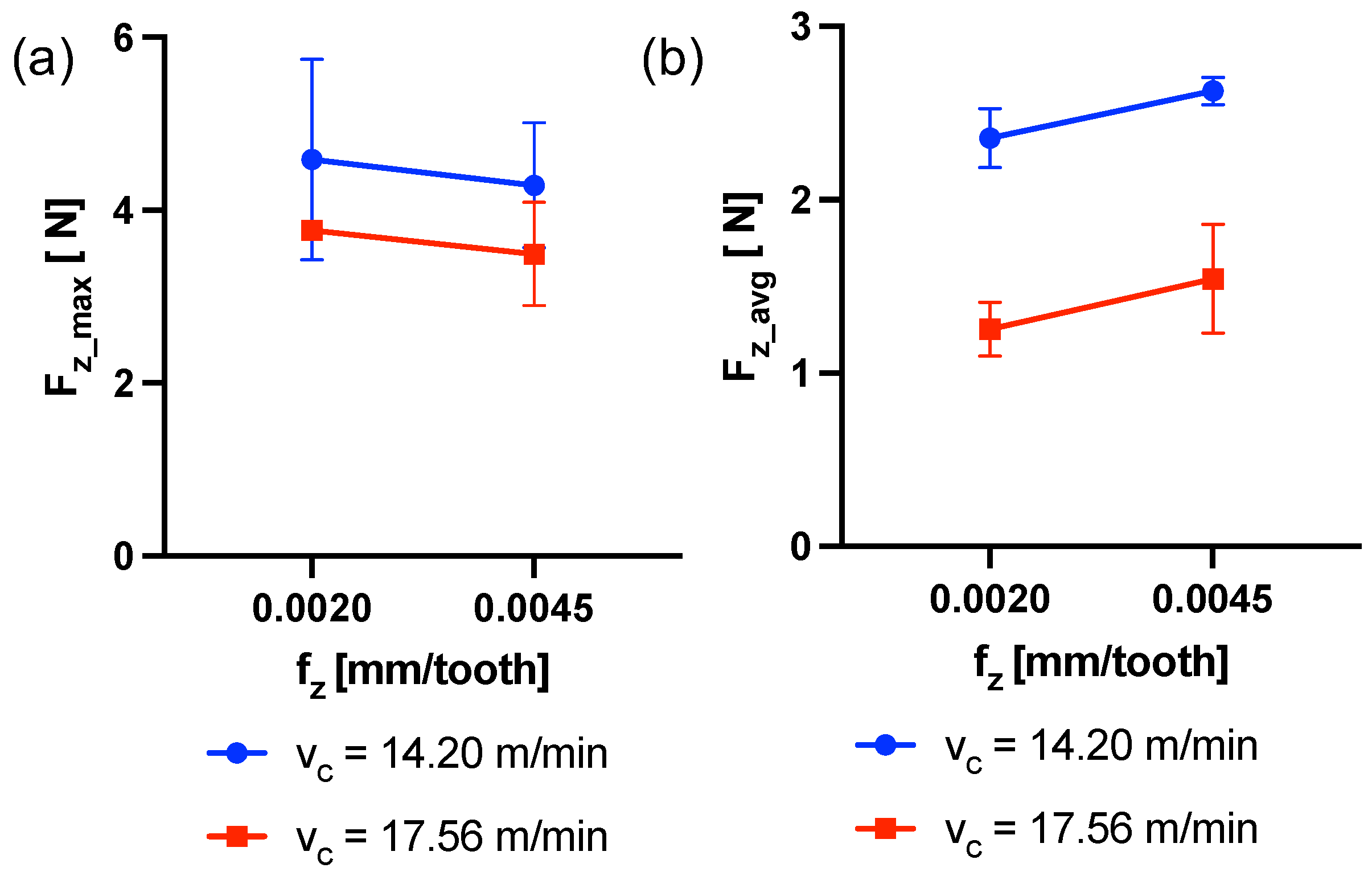
On the other hand,
has been shown to be influenced by both factors significantly. The obtained trends are in agreement with the theory of the chip formation process and the expected effect of the cutting parameters. Indeed, an increase in
is associated to an increase in
due to the fact that the thrust the tool exerts on the target material increases [
39,
40]. In fact, the feed per tooth significantly influences chip thickness and thus the resulting cutting force. On the contrary, an increment of
produces a decrease in
, caused by the material softening induced by the increment of temperature in the cutting region. When the cutting speed is high, the strain rate is also high, leading to an increase in temperature within the cutting zone. This, in turn, induces thermal softening in the workpiece, leading to a lower force being required to remove the chip [
41].
Typically, during the first stage of drilling, as the tool enters into the workpiece, plastic deformation occurs, whereby material in front of the chisel edge is pushed to the sides of the tool. As the drill penetrates deeper, the material deforms and flows plastically around the circumference of the hole, thus forming burrs [
42,
43,
44]. In this study, the results concerning the burr formation on the hole entrance have demonstrated a dependence on the interaction between the two cutting parameters, but mainly on
. Although higher
(i.e.,
n and/or
) typically increases the heat generated during the cutting process, which exacerbates burr formation due to thermal expansion and plastic deformation [
43], this article observes a reduction in burr height as
increases. This outcome could be linked to the dwell time inside the hole: lower feeds mean longer time and thus more defects at the entrance, high feeds mean shorter dwell time and thus smaller defects. Moreover, if it is assumed that the burr at the entrance of the hole is determined in the early stages of the whole deep-drilling process, it is possible to state that once the transient is completed, the burr height could be altered by the subsequent peck drilling steps. Although literature exists stating the contrary in other applications [
26], we found a different result, to which we give this preliminary explanation that is not yet supported by experiments. In order to have experimental evidence, a specific campaign should be organized. These results were not observed in the preliminary study of deep-hole microdrilling conducted by the same authors of this paper on pure magnesium [
27]. In that case the burr height produced by the 0.200 mm drill was shown to be dependent only on the cutting speed and not on the feed or their interaction. In light of this, we must take into consideration the dramatic impact of the size on the process at this scale. The effects of cutting tool size and, of course, cutting parameters, could be different depending on the scale and exhibit different behaviors [
45].
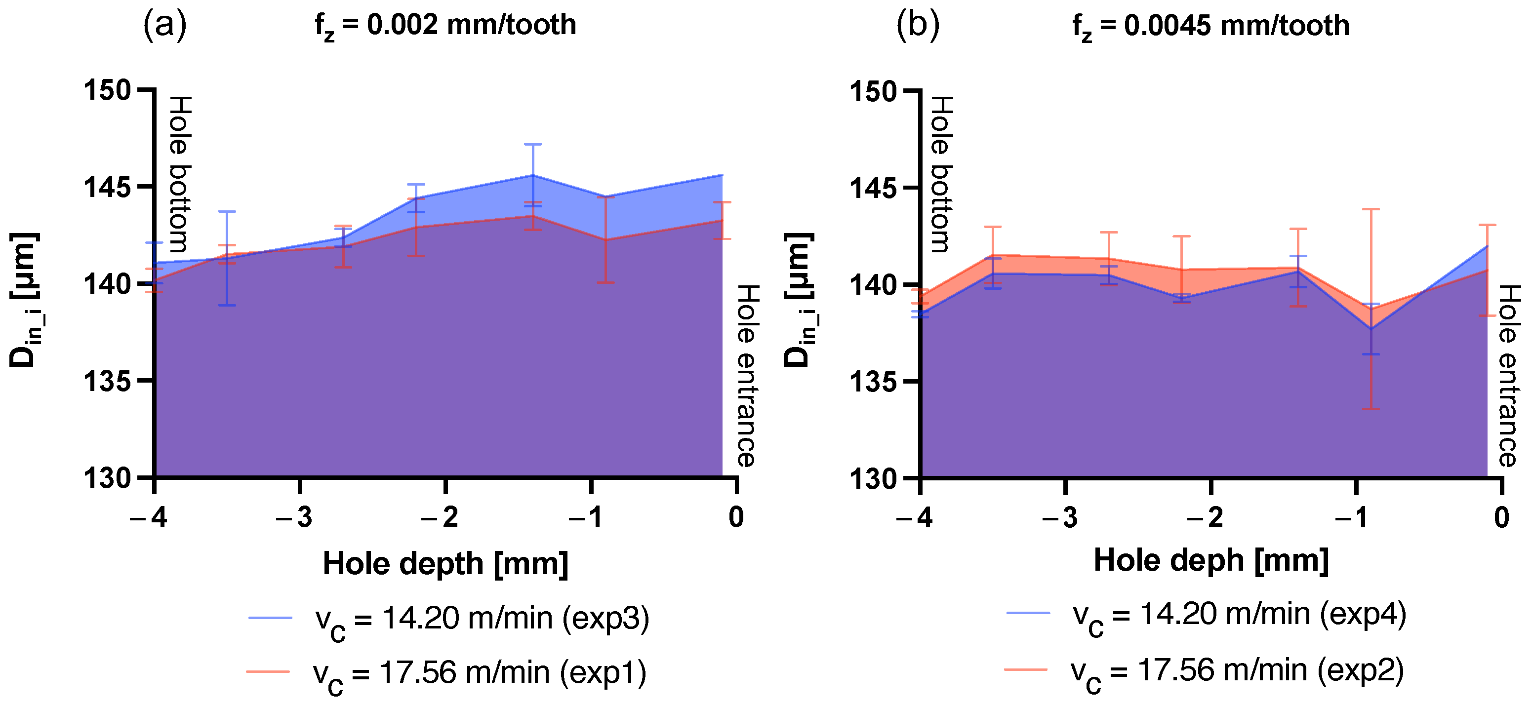
Since the stiffness and twisting of a cutting tool bit are highly dependent on diameter and length, a thinner and longer bit is more susceptible to deformation and dynamic instabilities [
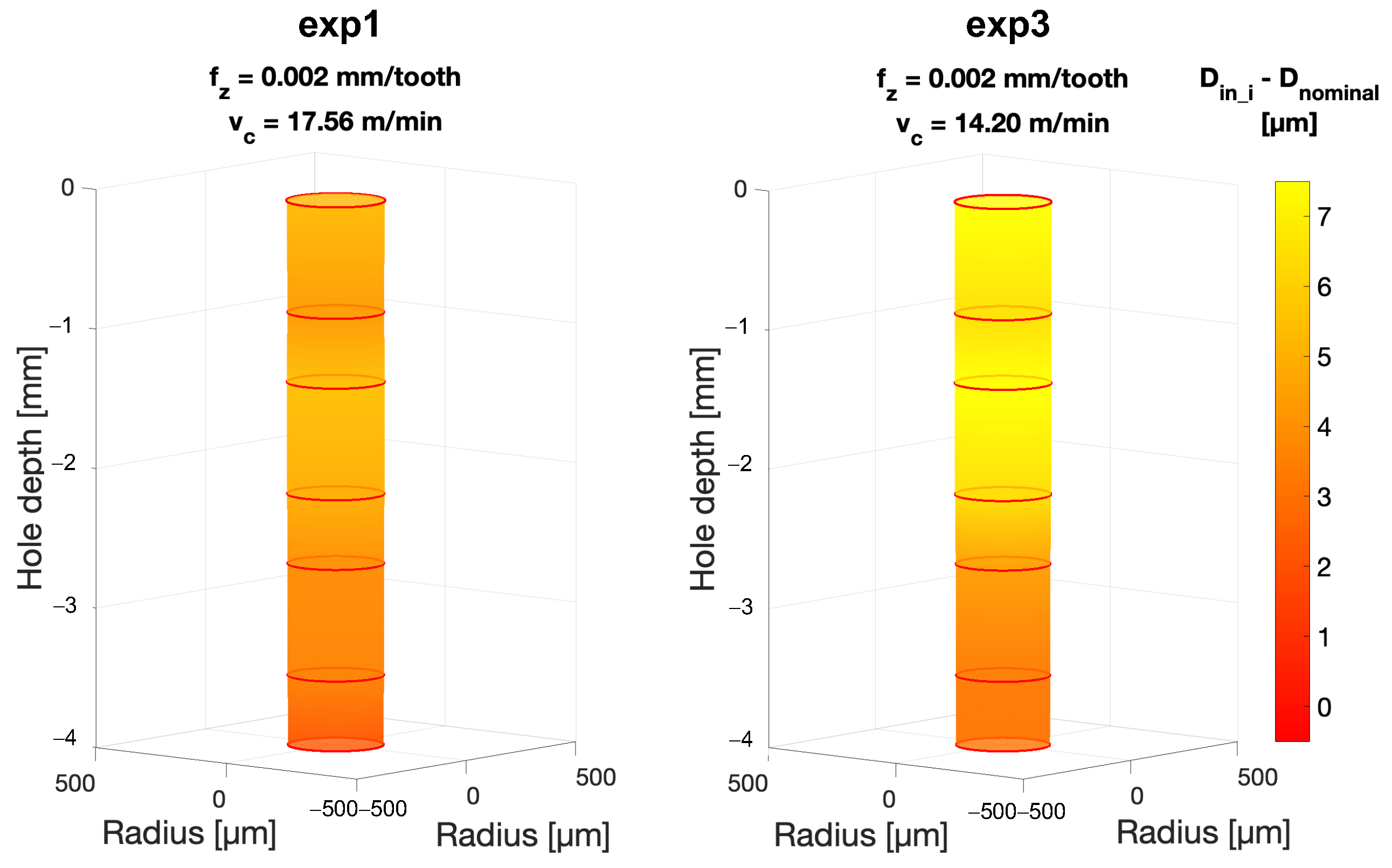
46]. This aspect makes such tools prone to buckling that leads to sudden deformation under load, such as the curving of a column under compression. Consequently, it is acceptable that the deformation of the cutting tool while rotating, together with its runout, causes deformations to the hole’s walls as it advances into the material to be removed. Larger diameters are mainly observed at the borehole entrance, while diameters come closer to the nominal by going deeper: the borehole entrance is the most affected region by these effects [
47]. This is reasonable because of the peck drilling strategy (i.e., several tool passages through the inlet of the hole), and it has been observed in these experiments. In light of this, if for higher feeds the thrust force increases, consequently the buckling tool curvature and thus the diameter enlargement should increase. However, the results reported here show the opposite of what would be expected: the entrance and inner diameters decrease by increasing the feed per tooth. This output, consequently, results from the sum of all the effects occurring during repeated tool passage. It is reasonable to assume that, increasing the dwell time of the tool inside the hole (i.e., with low feed per tooth) has a greater effect than increasing the thrust forces for this range of parameters.
To conclude, it must be noted that the most cylindrical shape is also associated with the most stable cutting condition in terms of thrust force, achieved in exp2 ( = 0.0045 mm/tooth, = 17.56 m/min) (Figure). This might represent a first hint in the force–geometry correlation.


 ,
, 


