Thick Glass High-Quality Cutting by Ultrafast Laser Bessel Beam Perforation-Assisted Separation


 and
and
Abstract
:1. Introduction
2. Experiment and Methods
2.1. Experimental Setup
2.2. Method
3. Results and Discussion
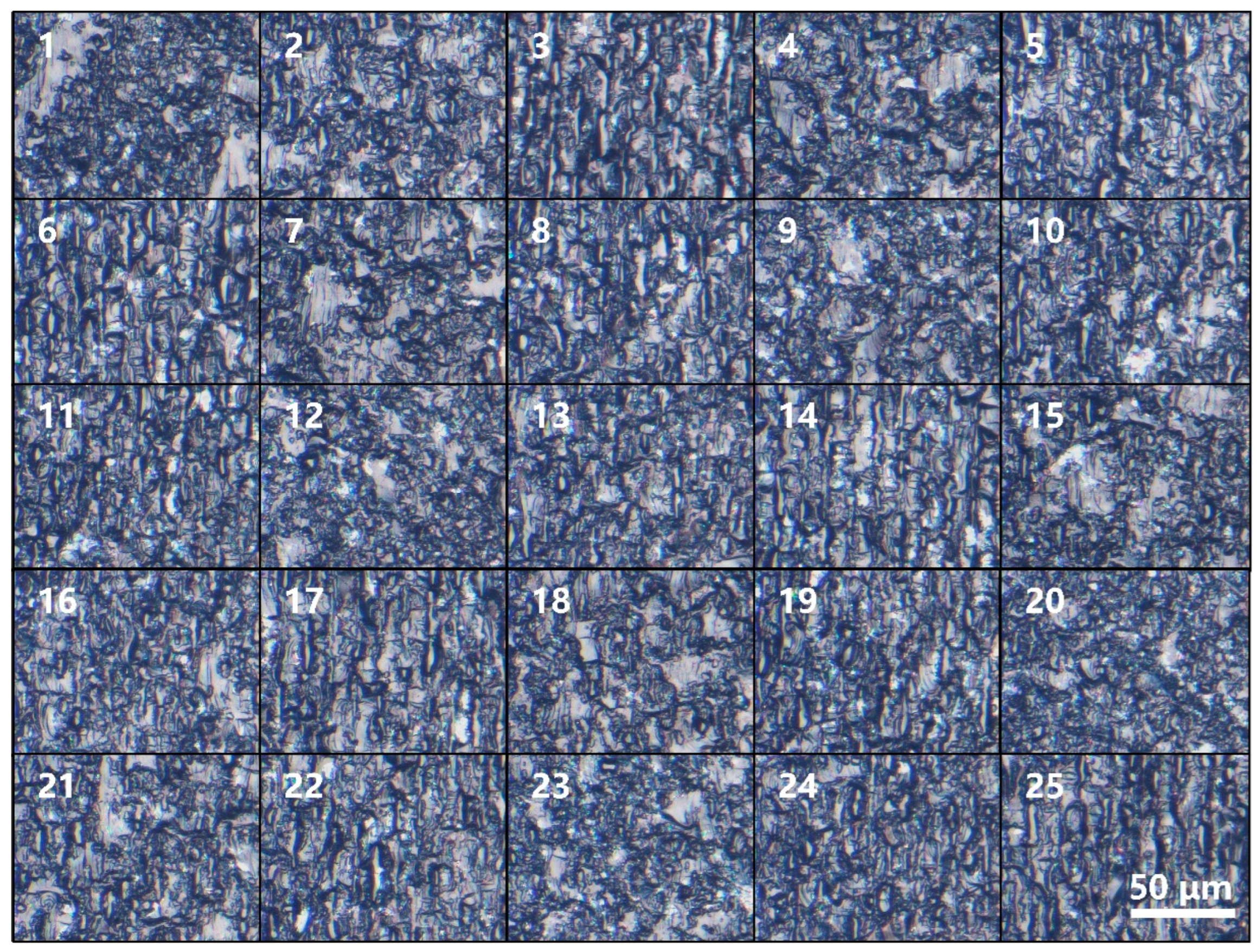
3.1. Variance Analysis of the L25 (53) Orthogonal Experiments
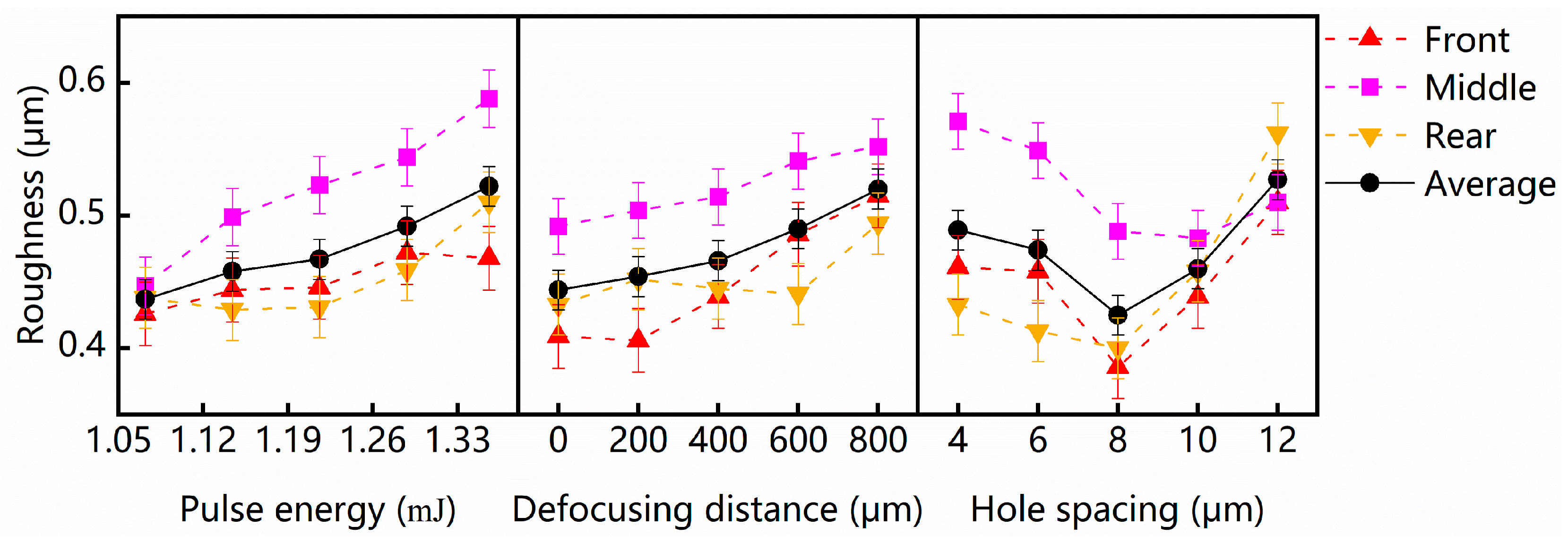
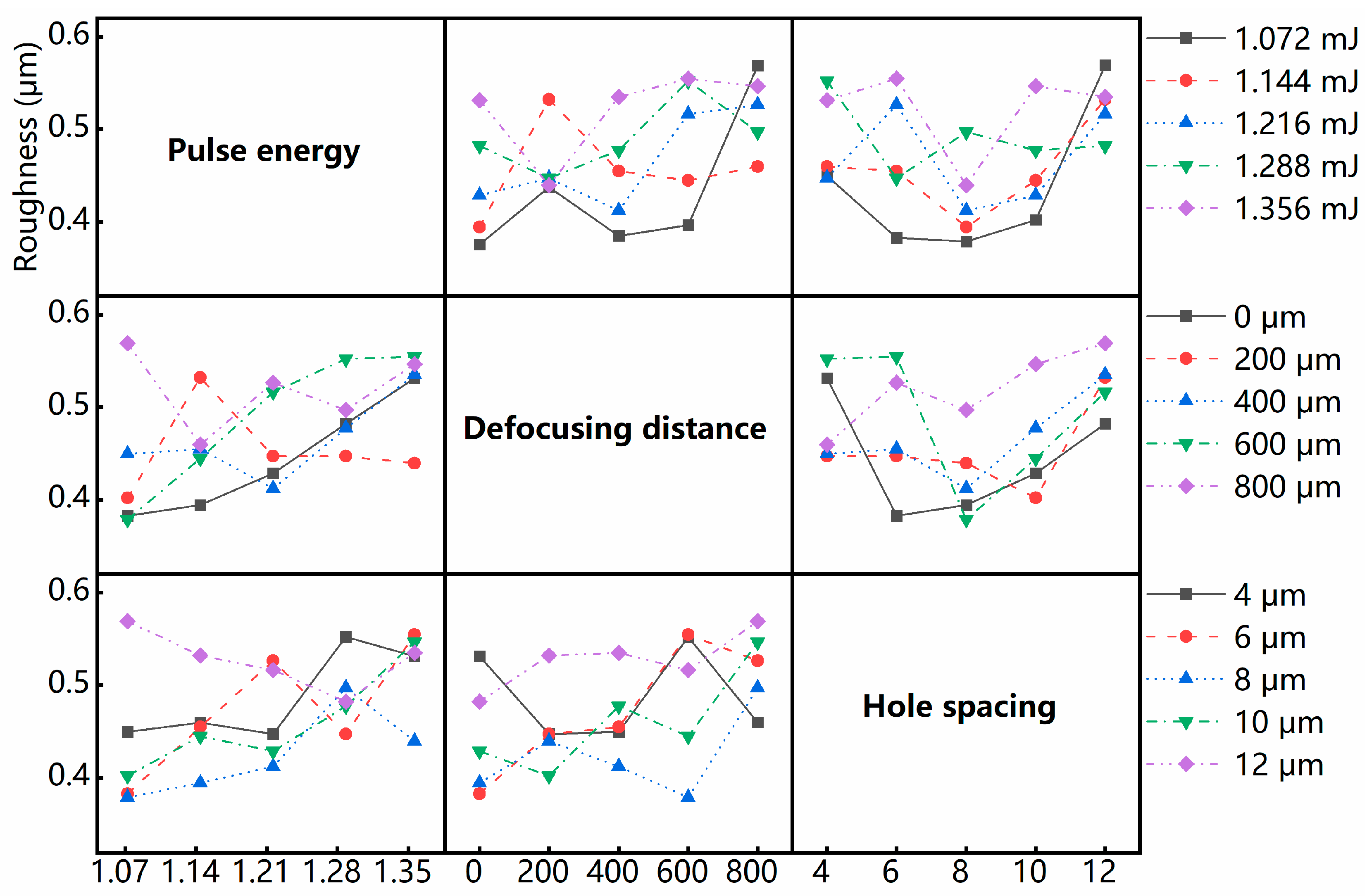
3.2. The Influence of Processing Parameters
3.3. Optimal Processing Parameters
4. Conclusions
Author Contributions
Funding
Data Availability Statement
Conflicts of Interest
References
- Vasudevan, A.; Kumaran, S.S.; Naresh, K.; Velmurugan, R. Experimental and analytical investigation of thermo-mechanical responses of pure epoxy and carbon/Kevlar/S-glass/E-glass/epoxy interply hybrid laminated composites for aerospace applications. Int. J. Polym. Anal. Charact. 2018, 23, 591–605. [Google Scholar] [CrossRef]
- Liang, Y.; Zhang, C.; Chen, X.; Zhang, T.; Yu, T.; Zhao, J. Modeling and analysis of the material removal rate for ultrasonic vibration–assisted polishing of optical glass BK7. Int. J. Adv. Manuf. Technol. 2022, 118, 627–639. [Google Scholar] [CrossRef]
- Overend, M.; Zammit, K. A computer algorithm for determining the tensile strength of float glass. Eng. Struct. 2012, 45, 68–77. [Google Scholar] [CrossRef]
- Zhimalov, A.B.; Sofinov, V.F.; Kondratenko, V.S.; Kaplina, T.V. Laser cutting of float glass during production. Glass Ceram. 2006, 63, 319–321. [Google Scholar] [CrossRef]
- Yang, B.; Xie, S.; Dai, F. Design of coupling device for laser cutting guided by water beam. Laser Technol. 2017, 41, 247–250. [Google Scholar]
- Matsumura, T.; Hiramatsu, T.; Shirakashi, T. A study on cutting force in the milling process of glass. In Proceedings of the 32nd North American Manufacturing Research Conference (NAMRC), Charlotte, NC, USA, 1–4 June 2004; pp. 463–470. [Google Scholar]
- Joglekar, A.P.; Liu, H.; Spooner, G.J.; Meyhofer, E.; Mourou, G.; Hunt, A.J. A study of the deterministic character of optical damage by femtosecond laser pulses and applications to nanomachining. Appl. Phys. B Lasers Opt. 2003, 77, 25–30. [Google Scholar] [CrossRef]
- Rodríguez, A.; Arriola, A.; Tavera, T.; Pérez, N.; Olaizola, S.M. Enhanced depth control of ultrafast laser micromachining of microchannels in soda-lime glass. Microelectron. Eng. 2012, 98, 672–675. [Google Scholar] [CrossRef]
- Dudutis, J.; Pipiras, J.; Stonys, R.; Daknys, E.; Kilikevicius, A.; Kasparaitis, A.; Raciukaitis, G.; Gecys, P. In-depth comparison of conventional glass cutting technologies with laser-based methods by volumetric scribing using Bessel beam and rear-side machining. Opt. Express 2020, 28, 32133–32151. [Google Scholar] [CrossRef] [PubMed]
- Sun, X.Y.; Zheng, J.F.; Liang, C.; Hu, Y.W.; Zhong, H.M.; Duan, J.A. Improvement of rear damage of thin fused silica by liquid-assisted femtosecond laser cutting. Appl. Phys. A Mater. Sci. Process. 2019, 125, 8. [Google Scholar] [CrossRef]
- Mitra, S.; Chanal, M.; Clady, R.; Mouskeftaras, A.; Grojo, D. Millijoule femtosecond micro-Bessel beams for ultra-high aspect ratio machining. Appl. Opt. 2015, 54, 7358–7365. [Google Scholar] [CrossRef]
- Shin, H.; Noh, J.; Kim, D. Bottom-up cutting method to maximize edge strength in femtosecond laser ablation cutting of ultra-thin glass. Opt. Laser Technol. 2021, 138, 106921. [Google Scholar] [CrossRef]
- Liao, K.; Wang, W.; Mei, X.; Liu, B. High quality full ablation cutting and stealth dicing of silica glass using picosecond laser Bessel beam with burst mode. Ceram. Int. 2022, 48, 9805–9816. [Google Scholar] [CrossRef]
- Feuer, A.; Thomas, J.U.; Freitag, C.; Weber, R.; Graf, T. Single-pass laser separation of 8 mm thick glass with a millijoule picosecond pulsed Gaussian–Bessel beam. Appl. Phys. A 2019, 125, 332. [Google Scholar] [CrossRef]
- Meyer, R.; Froehly, L.; Giust, R.; Del Hoyo, J.; Furfaro, L.; Billet, C.; Courvoisier, F. Extremely high-aspect-ratio ultrafast Bessel beam generation and stealth dicing of multi-millimeter thick glass. Appl. Phys. Lett. 2019, 114, 201105. [Google Scholar] [CrossRef]
- Tsai, W.J.; Gu, C.J.; Cheng, C.W.; Horng, J.B. Internal modification for cutting transparent glass using femtosecond Bessel beams. Opt. Eng. 2014, 53, 051503. [Google Scholar] [CrossRef]
- Duocastella, M.; Arnold, C.B. Bessel and annular beams for materials processing. Laser Photonics Rev. 2012, 6, 607–621. [Google Scholar] [CrossRef]
- Summers, A.M.; Yu, X.; Wang, X.; Raoul, M.; Nelson, J.; Todd, D.; Zigo, S.; Lei, S.; Trallero-Herrero, C.A. Spatial characterization of Bessel-like beams for strong-field physics. Opt. Express 2017, 25, 1646–1655. [Google Scholar] [CrossRef]
- Cheng, H.; Xia, C.; Kuebler, S.M.; Golvari, P.; Sun, M.; Zhang, M.; Yu, X. Generation of Bessel-beam arrays for parallel fabrication in two-photon polymerization. J. Laser Appl. 2021, 33, 012040. [Google Scholar] [CrossRef]
- Cheng, H.; Golvari, P.; Xia, C.; Sun, M.; Zhang, M.; Kuebler, S.M.; Yu, X. High-throughput microfabrication of axially tunable helices. Photonics Res. 2022, 10, 303–315. [Google Scholar] [CrossRef]
- Furumoto, T.; Hashimoto, Y.; Ogi, H.; Kawabe, T.; Yamaguchi, M.; Koyano, T.; Hosokawa, A. CO2 laser cleavage of chemically strengthened glass. J. Mater. Process. Technol. 2021, 289, 9. [Google Scholar] [CrossRef]
- Chuang, C.F.; Chen, K.S.; Chiu, T.C.; Yang, T.S.; Lin, M.C. Crafting interior holes on chemically strengthened thin glass based on ultrafast laser ablation and thermo-shock crack propagations. Sens. Actuators A Phys. 2020, 301, 111723. [Google Scholar] [CrossRef]
- Hoff, K.; Li, X.; Glaesemann, G.S. Laser Controlled Fracture Strength in Chemically Strengthened Glass. Opt. Soc. Am. 2010. [Google Scholar] [CrossRef]
- Neuenschwander, B.; Kramer, T.; Lauer, B.; Jaeggi, B. Burst mode with ps- and fs-pulses: Influence on the removal rate, surface quality and heat accumulation. In Proceedings of the Laser Applications in Microelectronic and Optoelectronic Manufacturing (LAMOM) XX, SPIE-INT SOC Optical Engineering, San Francisco, CA, USA, 7–12 February 2015. [Google Scholar]
- Jiao, J.; Wang, X. Cutting glass substrates with dual-laser beams. Opt. Lasers Eng. 2009, 47, 860–864. [Google Scholar]
- Flury, S.; Peutzfeldt, A.; Lussi, A. Influence of surface roughness on mechanical properties of two computer-aided design/computer-aided manufacturing (CAD/CAM) ceramic materials. Oper. Dent. 2012, 37, 617. [Google Scholar]
- Nie, X.; Chen, W.W.; Wereszczak, A.A.; Templeton, D.W. Effect of Loading Rate and Surface Conditions on the Flexural Strength of Borosilicate Glass. J. Am. Ceram. Soc. 2009, 92, 1287–1295. [Google Scholar]
- Shin, H.; Kim, D. Strength of ultra-thin glass cut by internal scribing using a femtosecond Bessel beam. Opt. Laser Technol. 2020, 129, 106307. [Google Scholar]
- Dobes, J.; Leal, J.E.S.; Profeta, J.; de Sousa, M.M.; Lepore, F.P.; Piratelli, A.; Arencibia, R.V. Effect of mechanical vibration on Ra, Rq, Rz, and Rt roughness parameters. Int. J. Adv. Manuf. Technol. 2017, 92, 393–406. [Google Scholar]
- Krenzer, U. SPSS survival manual. A step manual. A step by step guide to data analysis using SPSS for Windows. Homo-J. Comp. Hum. Biol. 2002, 53, 81–91. [Google Scholar]
- Yang, Z.; Duan, J.; Chen, H.; Liu, P.; Chen, J.; Dan, X. Chemically Strengthened Glass Fabricated by Picosecond Bessel Beam Cutting. Chin. J. Lasers 2019, 46, 1102010. [Google Scholar] [CrossRef]
- Bhuyan, M.K.; Jedrkiewicz, O.; Sabonis, V.; Mikutis, M.; Recchia, S.; Aprea, A.; Bollani, M.; Trapani, P.D. High-speed laser-assisted cutting of strong transparent materials using picosecond Bessel beams. Appl. Phys. A 2015, 120, 443–446. [Google Scholar]
- Jenne, M.; Flamm, D.; Ouaj, T.; Hellstern, J.; Kleiner, J.; Grossmann, D.; Koschig, M.; Kaiser, M.; Kumkar, M.; Nolte, S. High-quality tailored-edge cleaving using aberration-corrected Bessel-like beams. Opt. Lett. 2018, 43, 3164–3167. [Google Scholar] [CrossRef]
- Dietz, T.; Jenne, M.; Bauer, D.; Scharun, M.; Sutter, D.; Killi, A. Ultrafast thin-disk multi-pass amplifier system providing 1.9 kW of average output power and pulse energies in the 10 mJ range at 1 ps of pulse duration for glass-cleaving applications. Opt. Express 2020, 28, 11415–11423. [Google Scholar] [CrossRef] [PubMed]


| Process Parameters | Unit | Factor Level | ||||
|---|---|---|---|---|---|---|
| 1 | 2 | 3 | 4 | 5 | ||
| Pulse energy | (mJ) | 1.356 | 1.288 | 1.216 | 1.144 | 1.072 |
| Defocusing distance | (μm) | 0 | 200 | 400 | 600 | 800 |
| Hole spacing | (μm) | 4 | 6 | 8 | 10 | 12 |
| No. | Pulse Energy (mJ) | Defocusing Distance (μm) | Hole Spacing (μm) | Average Surface Roughness (μm) |
|---|---|---|---|---|
| 1 | 1.356 | 0 | 4 | 0.532 |
| 2 | 1.356 | 200 | 8 | 0.440 |
| 3 | 1.356 | 400 | 12 | 0.535 |
| 4 | 1.356 | 600 | 6 | 0.555 |
| 5 | 1.356 | 800 | 10 | 0.547 |
| 6 | 1.288 | 0 | 12 | 0.483 |
| 7 | 1.288 | 200 | 6 | 0.448 |
| 8 | 1.288 | 400 | 10 | 0.478 |
| 9 | 1.288 | 600 | 4 | 0.553 |
| 10 | 1.288 | 800 | 8 | 0.498 |
| 11 | 1.216 | 0 | 10 | 0.429 |
| 12 | 1.216 | 200 | 4 | 0.448 |
| 13 | 1.216 | 400 | 8 | 0.413 |
| 14 | 1.216 | 600 | 12 | 0.517 |
| 15 | 1.216 | 800 | 6 | 0.527 |
| 16 | 1.144 | 0 | 8 | 0.395 |
| 17 | 1.144 | 200 | 12 | 0.533 |
| 18 | 1.144 | 400 | 6 | 0.455 |
| 19 | 1.144 | 600 | 10 | 0.445 |
| 20 | 1.144 | 800 | 4 | 0.460 |
| 21 | 1.072 | 0 | 6 | 0.383 |
| 22 | 1.072 | 200 | 10 | 0.403 |
| 23 | 1.072 | 400 | 4 | 0.450 |
| 24 | 1.072 | 600 | 8 | 0.379 |
| 25 | 1.072 | 800 | 12 | 0.569 |
| Dependent Variable | Value | Mean Surface Roughness (μm) | Standard Error | 95% Confidence Interval | |
|---|---|---|---|---|---|
| Lower Bound | Upper Bound | ||||
| Pulse energy (mJ) | 1.072 | 0.437 | 0.015 | 0.404 | 0.47 |
| 1.144 | 0.458 | 0.015 | 0.425 | 0.49 | |
| 1.216 | 0.467 | 0.015 | 0.434 | 0.5 | |
| 1.288 | 0.492 | 0.015 | 0.459 | 0.525 | |
| 1.356 | 0.522 | 0.015 | 0.489 | 0.555 | |
| Defocusing distance (μm) | 0 | 0.444 | 0.015 | 0.412 | 0.477 |
| 200 | 0.454 | 0.015 | 0.422 | 0.487 | |
| 400 | 0.466 | 0.015 | 0.433 | 0.499 | |
| 600 | 0.49 | 0.015 | 0.457 | 0.523 | |
| 800 | 0.52 | 0.015 | 0.487 | 0.553 | |
| Hole spacing (μm) | 4 | 0.489 | 0.015 | 0.456 | 0.521 |
| 6 | 0.474 | 0.015 | 0.441 | 0.506 | |
| 8 | 0.425 | 0.015 | 0.392 | 0.458 | |
| 10 | 0.46 | 0.015 | 0.428 | 0.493 | |
| 12 | 0.527 | 0.015 | 0.495 | 0.56 | |
| Thickness (mm) | Surface Roughness (μm) | Source | |
|---|---|---|---|
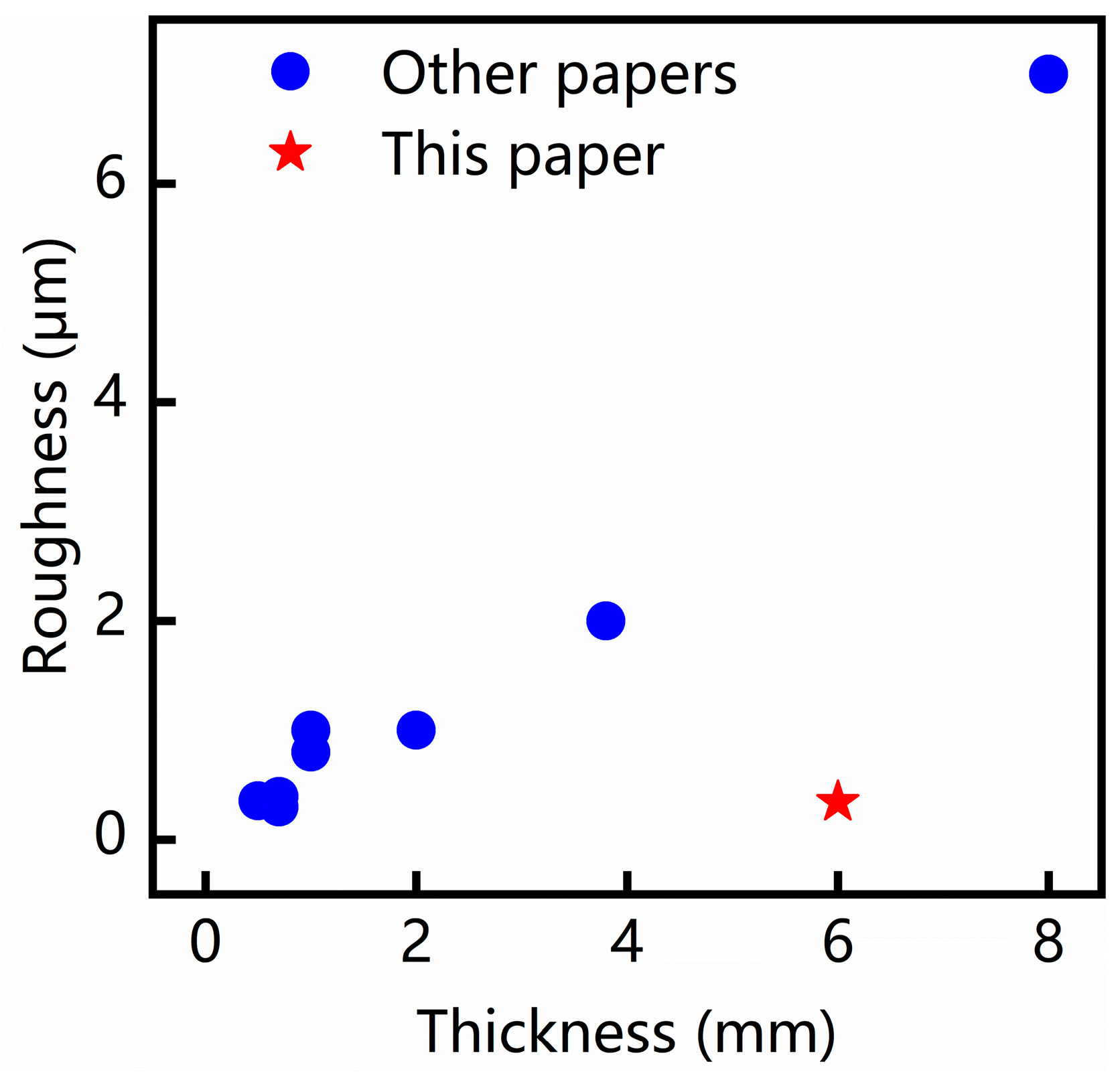
| 0.5 | Silica glass | 0.355 | K. Liao et al. [13] |
| 0.7 | Chemically strengthened glass | 0.395 | Z. Yang et al. [31] |
| 0.7 | Tempered glass | 0.3 | M.K. Bhuyan et al. [32] |
| 1 | Soda-lime glass | 1.0 | J. Dudutis et al. [9] |
| 2 | Silicate glass | 0.8 | M. Jenne et al. [33] |
| 3.8 | Float glass | 2.30 | T. Dietz et al. [34] |
| 8 | Soda-lime glass | 7.0 | A. Feuer et al. [14] |
| 6 | Soda-lime glass | 0.343 | This paper |
Disclaimer/Publisher’s Note: The statements, opinions and data contained in all publications are solely those of the individual author(s) and contributor(s) and not of MDPI and/or the editor(s). MDPI and/or the editor(s) disclaim responsibility for any injury to people or property resulting from any ideas, methods, instructions or products referred to in the content. |
© 2024 by the authors. Licensee MDPI, Basel, Switzerland. This article is an open access article distributed under the terms and conditions of the Creative Commons Attribution (CC BY) license (https://creativecommons.org/licenses/by/4.0/).
Share and Cite
Chen, S.; Luo, Y.; Fan, X.; Wu, C.; Zhang, G.; Huang, Y.; Rong, Y.; Chen, L. Thick Glass High-Quality Cutting by Ultrafast Laser Bessel Beam Perforation-Assisted Separation. Micromachines 2024, 15, 854. https://doi.org/10.3390/mi15070854
Chen S, Luo Y, Fan X, Wu C, Zhang G, Huang Y, Rong Y, Chen L. Thick Glass High-Quality Cutting by Ultrafast Laser Bessel Beam Perforation-Assisted Separation. Micromachines. 2024; 15(7):854. https://doi.org/10.3390/mi15070854
Chicago/Turabian StyleChen, Suwan, Yuxuan Luo, Xinhu Fan, Congyi Wu, Guojun Zhang, Yu Huang, Youmin Rong, and Long Chen. 2024. "Thick Glass High-Quality Cutting by Ultrafast Laser Bessel Beam Perforation-Assisted Separation" Micromachines 15, no. 7: 854. https://doi.org/10.3390/mi15070854
APA StyleChen, S., Luo, Y., Fan, X., Wu, C., Zhang, G., Huang, Y., Rong, Y., & Chen, L. (2024). Thick Glass High-Quality Cutting by Ultrafast Laser Bessel Beam Perforation-Assisted Separation. Micromachines, 15(7), 854. https://doi.org/10.3390/mi15070854