
A Flexible Temperature Sensor Integrated at Needle Tip for In Situ Acupoint Temperature Monitoring

 , ,
, , 
Abstract
:1. Introduction
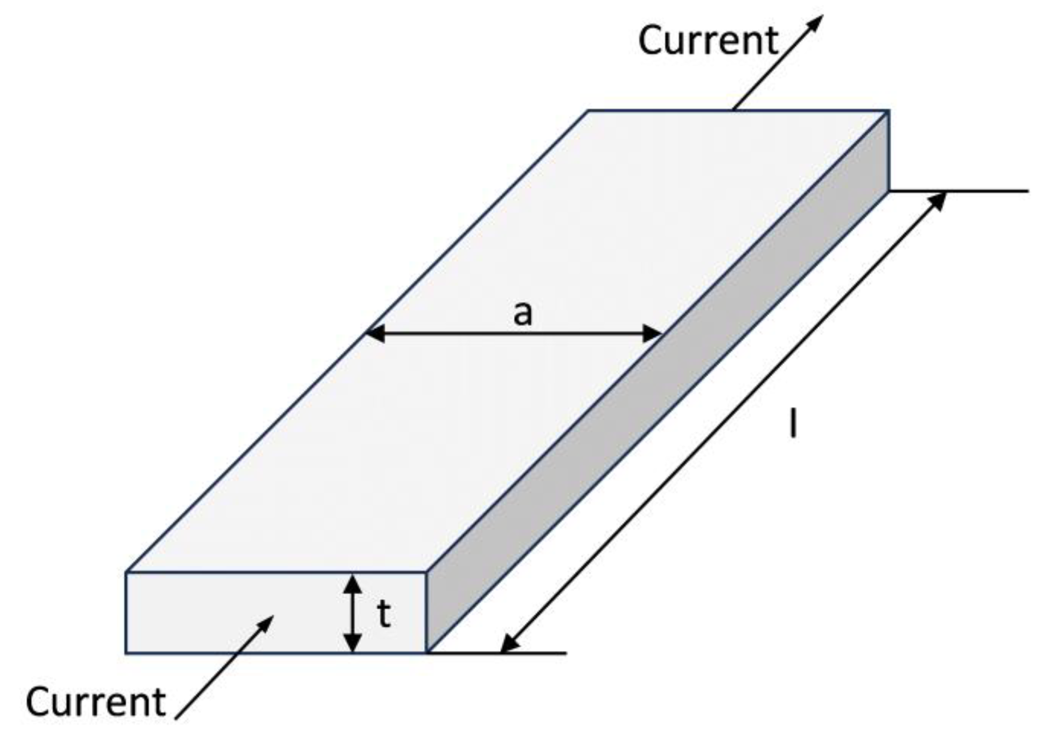
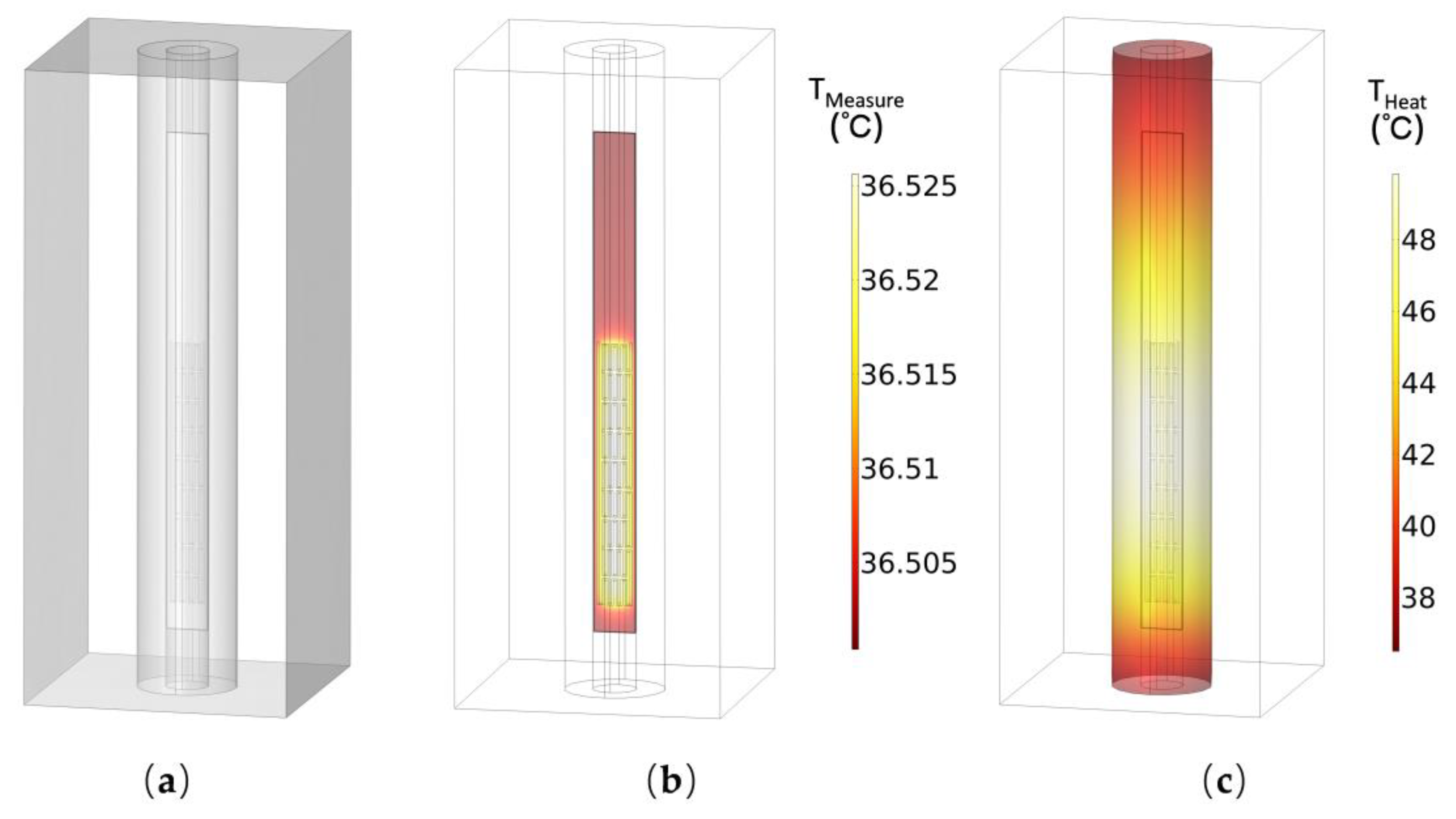
2. Design
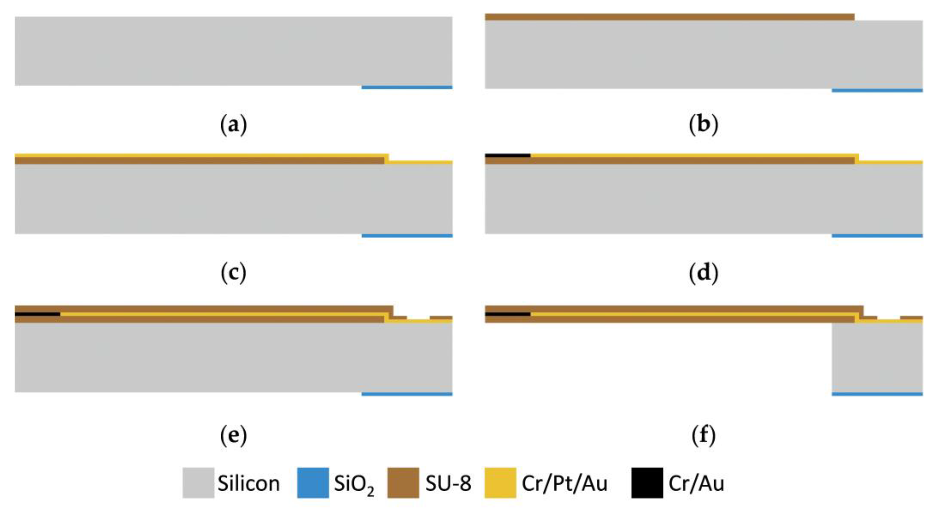
3. Fabrication Process
4. Test
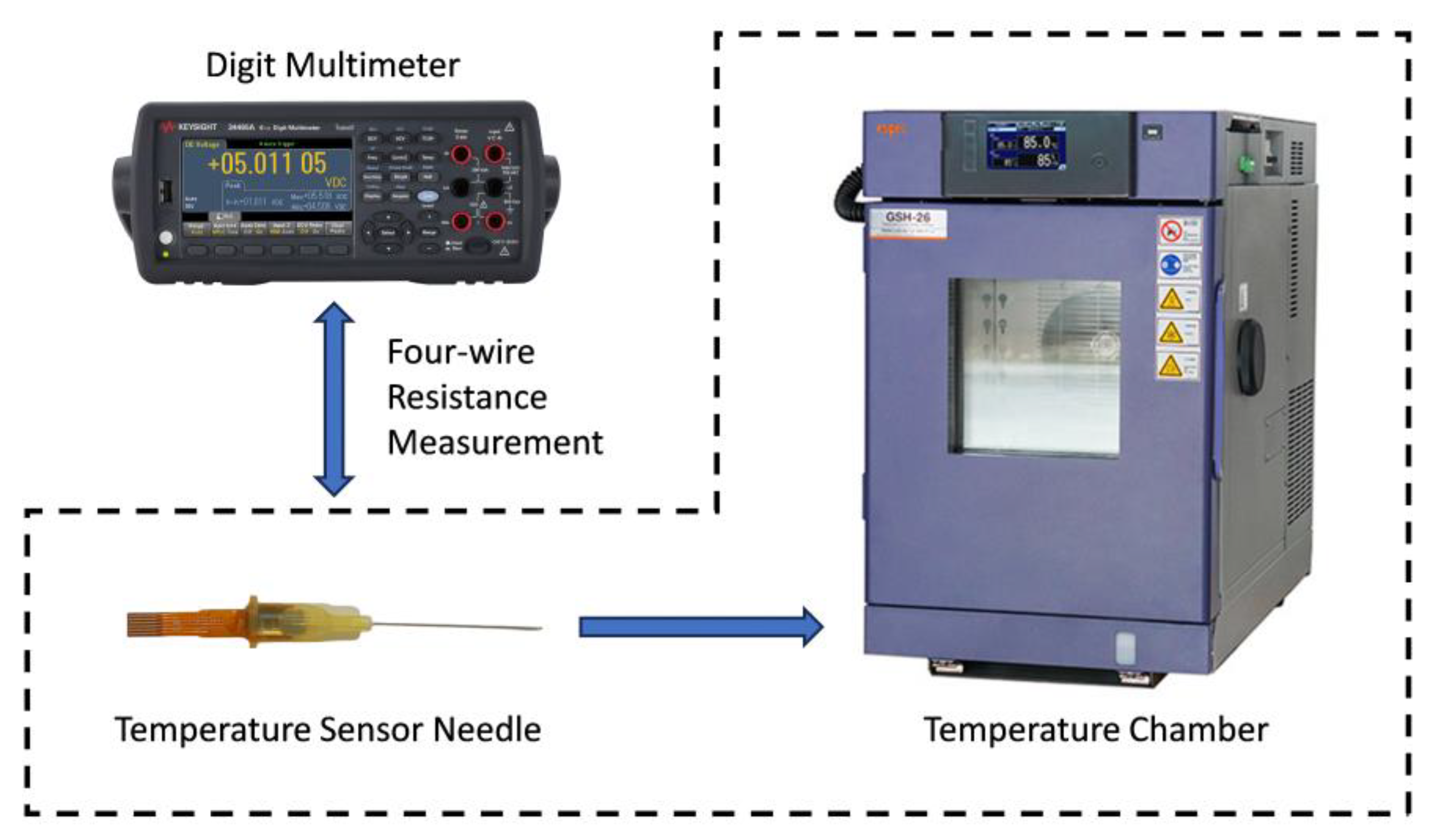
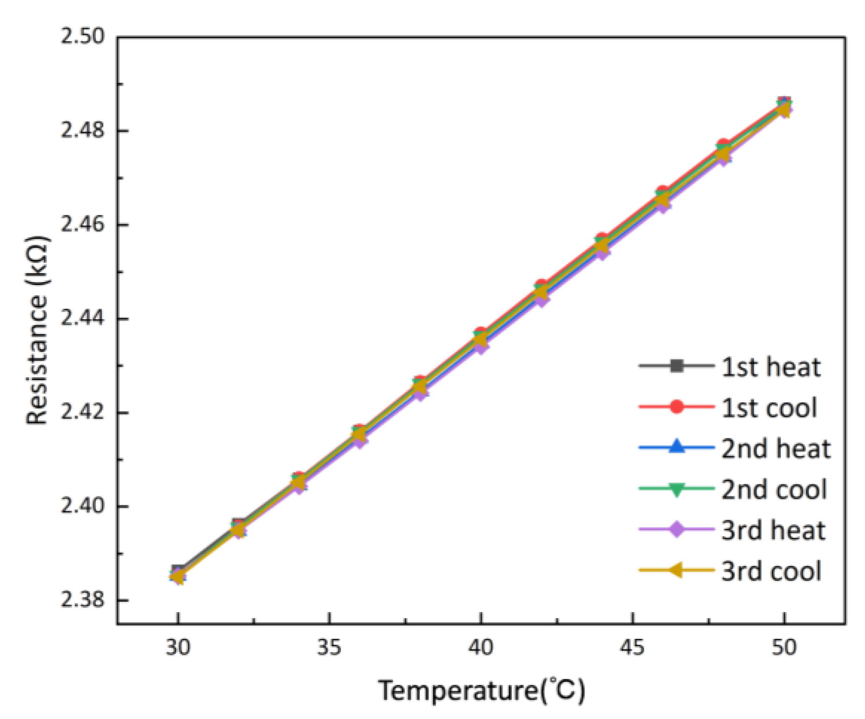
4.1. Performance Test
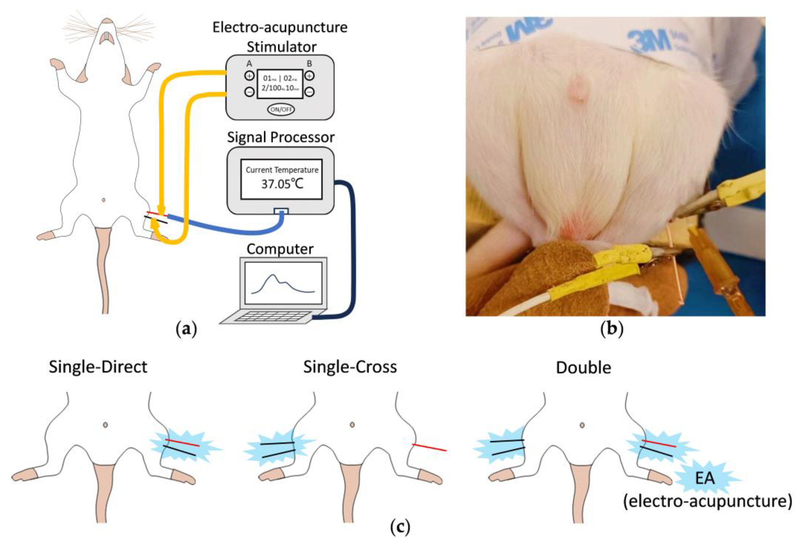
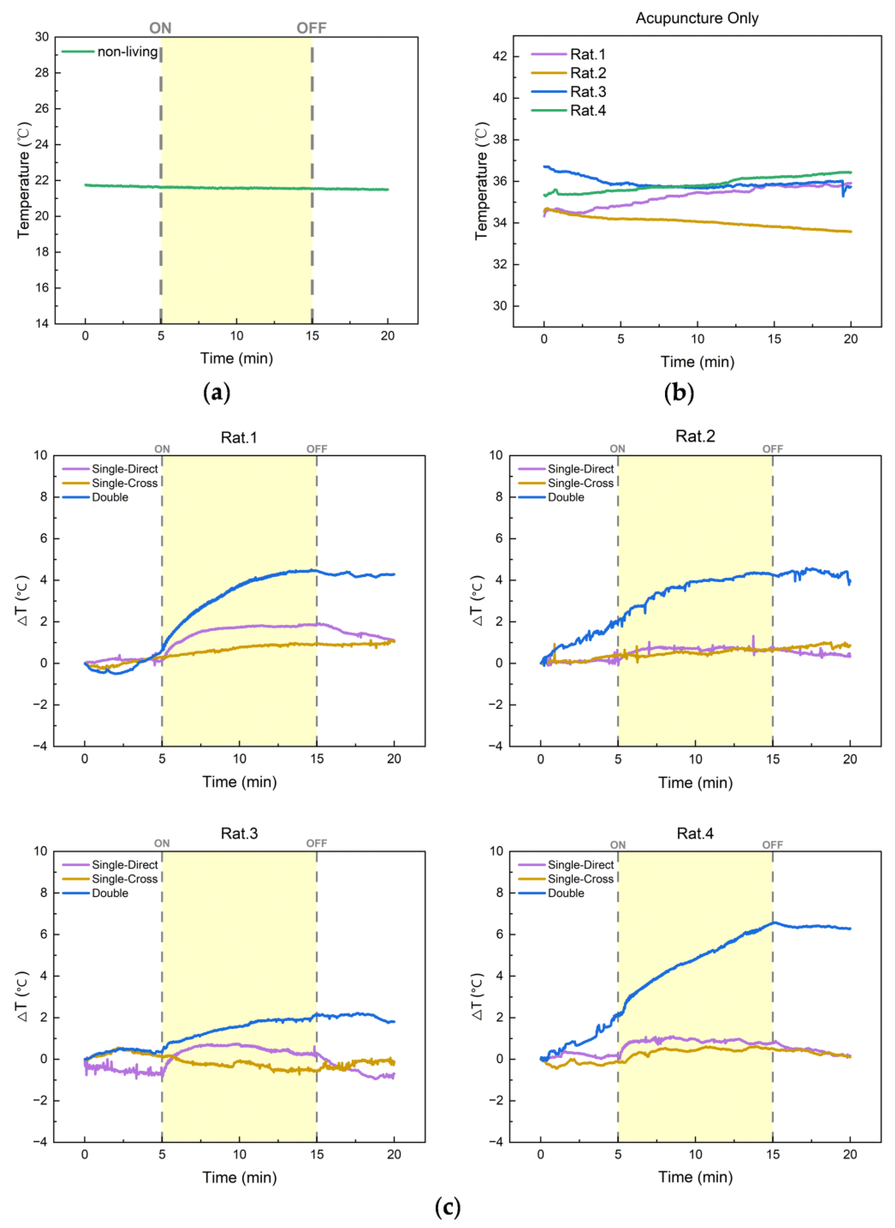
4.2. In Vivo In Situ Acupoint Temperature Monitoring in Rats
5. Conclusions
Author Contributions
Funding
Institutional Review Board Statement
Data Availability Statement
Acknowledgments
Conflicts of Interest
References
- Chen, R.; Kang, M. Acupoint Heat-Sensitization and Its Clinical Significance. J. Tradit. Chin. Med. 2006, 47, 905–906. [Google Scholar]
- Lingyun, G.A.O.; Xianglong, H.U.; Xiaoyang, X.U.; Baohua, W.U.; Ling, C. Measurement of the Temperature in Deep Tissues along the Governor Vessel. Acupunct. Res. 2006, 31, 159–162. [Google Scholar]
- Wu, Z.-Y.; Liu, X.-L.; Hong, W.-X.; Zhang, D. Research on the correlation between the temperature asymmetry at acupoints of healthy and affected side and the severity index of facial paralysis. Chin. Acupunct. Moxibustion 2010, 30, 953–956. [Google Scholar]
- Chen, M.; Wu, Z.; Hu, X.; Xu, J. Effect of Acupuncture on Partial Oxygen Pressure and Temperature of deep tissues along Large Intestine Channel in 30 Normal Volunteer Subfects. Chin. J. Basic Med. Tradit. Chin. Med. 2011, 17, 553–555. [Google Scholar]
- Ma, H.; Bai, X.; Wang, S.; Li, S.; Tang, L.; Zhang, D. Influences of electroacupuncture and moxibustion on temperature and blood flow in local tissue. J. Beijing Univ. Tradit. Chin. Med. 2013, 36, 558–562. [Google Scholar]
- Tang, L.; Wang, S.; Li, S.; Zhang, D. Effects of superficial temperature and transcutaneous oxygen pressure of yingxiang point induced by EA Hogu. Chin. J. Basic Med. Tradit. Chin. Med. 2014, 20, 1277–1280. [Google Scholar]
- Yang, Z.; Zhou, M.; Wang, X.; Zhao, Y.; Chen, Z.; Lan, Y.; Xu, T.; Zhao, Y.; Zhao, L. Review on skin temperature of acupoints. Chin. Acupunct. Moxibustion 2017, 37, 109–114. [Google Scholar] [CrossRef]
- Zheng, S.; Xu, J.; Pan, X.; Sa, Z.; Zhu, X.; Yang, X.; Su, M.; Shen, C. Law of changes in temperature of stomach channel’s acupoints and the effects of electrical acupuncture during gastrointestinal function skewness. China J. Tradit. Chin. Med. Pharm. 2017, 32, 5518–5520. [Google Scholar]
- Bai, H.; Ji, B.; Zhao, G.; Wang, D.; Yan, M.; Sun, X.; Lu, Y.; Dai, J.; Liu, Y.; Ge, Y.; et al. Influence of high frequency electroacupuncture on skin temperature around meridian acupoints, and non-menridian sham acupoints in rats with myocardial ischemia. J. Beijing Univ. Tradit. Chin. Med. 2018, 41, 148–153. [Google Scholar]
- Ma, H.; Wang, S.; Song, X.; Guo, M.; Wang, Y.; Li, R.; Gao, R. Effect of Herbal Patching of Mahuang (Herba Ephedrae) and Huangqin (Radix Scutellariae) at Feishu (BL13) on the Surface Temperature of Neck, Chest and Back Acupoints in Healthy Subjects. J. Tradit. Chin. Med. 2023, 64, 1455–1461. [Google Scholar]
- Cui, R.; Liu, J.; Ma, W.; Hu, J.; Zhou, X.; Li, H.; Hu, J. A needle temperature microsensor for in vivo and real-time measurement of the temperature in acupoints. Sens. Actuators A Phys. 2005, 119, 128–132. [Google Scholar] [CrossRef]
- Tanaka, M. An industrial and applied review of new MEMS devices features. Microelectron. Eng. 2007, 84, 1341–1344. [Google Scholar] [CrossRef]
- Bell, D.J.; Lu, T.J.; Fleck, N.A.; Spearing, S.M. MEMS actuators and sensors: Observations on their performance and selection for purpose. J. Micromechanics Microengineering 2005, 15, S153–S164. [Google Scholar] [CrossRef]
- Khan, Y.; Ostfeld, A.E.; Lochner, C.M.; Pierre, A.; Arias, A.C. Monitoring of Vital Signs with Flexible and Wearable Medical Devices. Adv. Mater. 2016, 28, 4373–4395. [Google Scholar] [CrossRef] [PubMed]
- Lü, X.Z.; Jiang, J.A.; Wang, H.; Gao, Q.B.; Zhao, S.B.; Li, N.; Yang, J.Y.; Wang, S.L.; Bao, W.M.; Chen, R.J. Sensitivity-Compensated Micro-Pressure Flexible Sensor for Aerospace Vehicle. Sensors 2019, 19, 72. [Google Scholar] [CrossRef]
- Xie, M.Y.; Hisano, K.; Zhu, M.Z.; Toyoshi, T.; Pan, M.; Okada, S.; Tsutsumi, O.; Kawamura, S.; Bowen, C. Flexible Multifunctional Sensors for Wearable and Robotic Applications. Adv. Mater. Technol. 2019, 4, 1800626. [Google Scholar] [CrossRef]
- Segev-Bar, M.; Haick, H. Flexible Sensors Based on Nanoparticles. Acs Nano 2013, 7, 8366–8378. [Google Scholar] [CrossRef]
- Xiao, S.Y.; Che, L.F.; Li, X.X.; Wang, Y.L. A cost-effective flexible MEMS technique for temperature sensing. Microelectron. J. 2007, 38, 360–364. [Google Scholar] [CrossRef]
- Li, K.-S.; Chao, T.-Y.; Cheng, Y.-T.; Chen, J.-K.; Chen, Y.-S. Temperature sensing probe integrated with an SU-8 flexible ribbon cable for heart surgery application. In Proceedings of the 16th International Solid-State Sensors, Actuators and Microsystems Conference, Beijing, China, 5–9 June 2011; pp. 2180–2183. [Google Scholar]
- Cui, Z.; Poblete, F.R.; Zhu, Y. Tailoring the Temperature Coefficient of Resistance of Silver Nanowire Nanocomposites and their Application as Stretchable Temperature Sensors. Acs Appl. Mater. Interfaces 2019, 11, 17836–17842. [Google Scholar] [CrossRef]
- Park, J.S.; Lee, D.S.; Nho, H.W.; Kim, D.S.; Hwang, T.H.; Lee, N.K. Flexible Platinum Temperature Sensor Embedded in Polyimide Films for Curved Surface Temperature Monitoring Applications: Skin Temperature of Human Body. Sens. Mater. 2017, 29, 1275–1283. [Google Scholar] [CrossRef]
- Jiang, H.C.; Huang, M.; Yu, Y.B.; Tian, X.Y.; Zhao, X.H.; Zhang, W.L.; Zhang, J.F.; Huang, Y.F.; Yu, K. Integrated Temperature and Hydrogen Sensors with MEMS Technology. Sensors 2018, 18, 94. [Google Scholar] [CrossRef] [PubMed]
- Liu, G.F.; Chen, X.L.; Li, X.M.; Wang, C.H.; Tian, H.M.; Chen, X.M.; Nie, B.B.; Shao, J.Y. Flexible, Equipment-Wearable Piezoelectric Sensor With Piezoelectricity Calibration Enabled by In-Situ Temperature Self-Sensing. IEEE Trans. Ind. Electron. 2022, 69, 6381–6390. [Google Scholar] [CrossRef]
- He, Q.P.; Zhang, W.Q.; Sheng, T.Y.; Gong, Z.; Dong, Z.H.; Zhang, D.Y.; Jiang, Y.G. Flexible conductivity-temperature-depth-strain (CTDS) sensor based on a CNT/PDMS bottom electrode for underwater sensing. Flex. Print. Electron. 2022, 7, 045002. [Google Scholar] [CrossRef]
- Wang, X.Y.; Chen, X.R.; Deng, Y.; Cheung, Y.K.; Jiang, P.; Xu, W.; Yu, H.Y.; IEEE. A Flexible Thermal Flow Sensor with Quadruple Heaters and Suspended Structure for Performance Enhancement. In Proceedings of the 35th IEEE International Conference on Micro Electro Mechanical Systems Conference (IEEE MEMS), Tokyo, Japan, 9–13 January 2022; pp. 652–655. [Google Scholar]
- Kreider, K.G.; Ripple, D.C.; Kimes, A.A. Thin-film resistance thermometers on silicon wafers. Meas. Sci. Technol. 2009, 20, 045206. [Google Scholar] [CrossRef]
- Riddle, J.L.; Furukawa, G.T.; Plumb, H.H. Platinum Resistance Thermometry; National Bureau of Standards: Gaithersburg, MD, USA, 1973; Volume 126. [Google Scholar]
- Bass, J. Deviations from Matthiessen’s Rule. Adv. Phys. 1972, 21, 431–604. [Google Scholar] [CrossRef]
- Fuchs, K. The conductivity of thin metallic films according to the electron theory of metals. Proc. Camb. Philos. Soc. 1938, 34, 100–108. [Google Scholar] [CrossRef]
- Sondheimer, E.H. The mean free path of electrons in metals. Adv. Phys. 1952, 1, 1–42. [Google Scholar] [CrossRef]
- Mayadas, A.F.; Shatzkes, M.; Janak, J.F. Electrical Resistivity Model for Polycrystalline Films: The Case of Specular Reflection at External Surfaces. Appl. Phys. Lett. 1969, 14, 345–347. [Google Scholar] [CrossRef]
- Mayadas, A.F.; Shatzkes, M. Electrical-Resistivity Model for Polycrystalline Films: The Case of Arbitrary Reflection at External Surfaces. Phys. Rev. B 1970, 1, 1382–1389. [Google Scholar] [CrossRef]
- Zhang, X.G.; Butler, W.H. Conductivity of metallic films and multilayers. Phys. Rev. B 1995, 51, 10085–10103. [Google Scholar] [CrossRef]
- Lacy, F. Developing a theoretical relationship between electrical resistivity, temperature, and film thickness for conductors. Nanoscale Res. Lett. 2011, 6, 1–14. [Google Scholar] [CrossRef] [PubMed]
- Vancea, J.; Hoffmann, H.; Kastner, K. Mean Free-Path and Effective Density of Conduction Electrons in Polycrystalline Metal-Films. Thin Solid Film. 1984, 121, 201–216. [Google Scholar] [CrossRef]
- Kim, B.J.; Meng, E. Review of polymer MEMS micromachining. J. Micromechanics Microengineering 2016, 26, 013001. [Google Scholar] [CrossRef]
- Li, Z. Experimental acupuncture science. China Press Tradit. Chin. Med. 2003, 314, 6. [Google Scholar]
- Yamada, K. Energetics of muscle contraction: Further trials. J. Physiol. Sci. 2017, 67, 19–43. [Google Scholar] [CrossRef]


Disclaimer/Publisher’s Note: The statements, opinions and data contained in all publications are solely those of the individual author(s) and contributor(s) and not of MDPI and/or the editor(s). MDPI and/or the editor(s) disclaim responsibility for any injury to people or property resulting from any ideas, methods, instructions or products referred to in the content. |
© 2024 by the authors. Licensee MDPI, Basel, Switzerland. This article is an open access article distributed under the terms and conditions of the Creative Commons Attribution (CC BY) license (https://creativecommons.org/licenses/by/4.0/).
Share and Cite
Song, C.; Yu, Z.; Feng, W.; Sun, K.; Wen, C.; Zhang, S.; Yu, S.; Li, X. A Flexible Temperature Sensor Integrated at Needle Tip for In Situ Acupoint Temperature Monitoring. Micromachines 2024, 15, 924. https://doi.org/10.3390/mi15070924
Song C, Yu Z, Feng W, Sun K, Wen C, Zhang S, Yu S, Li X. A Flexible Temperature Sensor Integrated at Needle Tip for In Situ Acupoint Temperature Monitoring. Micromachines. 2024; 15(7):924. https://doi.org/10.3390/mi15070924
Chicago/Turabian StyleSong, Ci, Zheng Yu, Weiwen Feng, Ke Sun, Chuanbiao Wen, Shengyan Zhang, Shuguang Yu, and Xinxin Li. 2024. "A Flexible Temperature Sensor Integrated at Needle Tip for In Situ Acupoint Temperature Monitoring" Micromachines 15, no. 7: 924. https://doi.org/10.3390/mi15070924
APA StyleSong, C., Yu, Z., Feng, W., Sun, K., Wen, C., Zhang, S., Yu, S., & Li, X. (2024). A Flexible Temperature Sensor Integrated at Needle Tip for In Situ Acupoint Temperature Monitoring. Micromachines, 15(7), 924. https://doi.org/10.3390/mi15070924