
Application of a Modified First-Order Plate Theory to Structural Analysis of Sensitive Elements in a Pyroelectric Detector
 , ,
, ,
Abstract
:1. Introduction
2. Basic Equations
3. The Modified First-Order Plate Theory
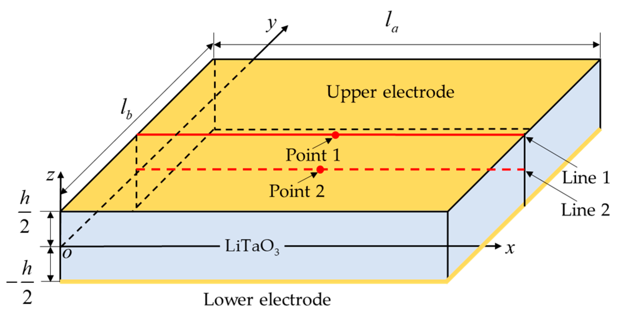
3.1. Elastic Boundary Conditions
3.2. Thermal Boundary Conditions
3.3. Electrical Boundary Conditions
4. Verification of Plate Theory and Discussion
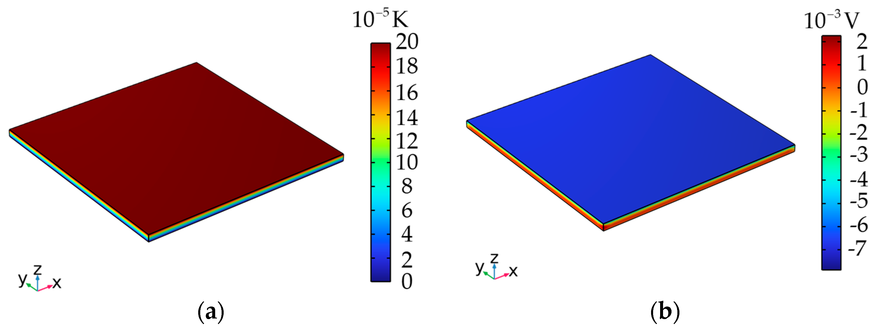
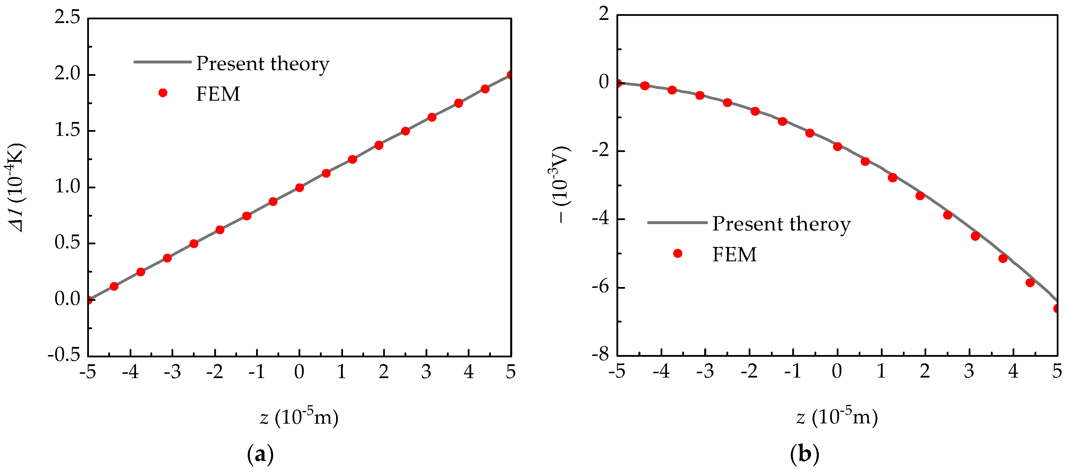
4.1. Verification of 3D Finite Element
4.2. Verification of Experimental Results
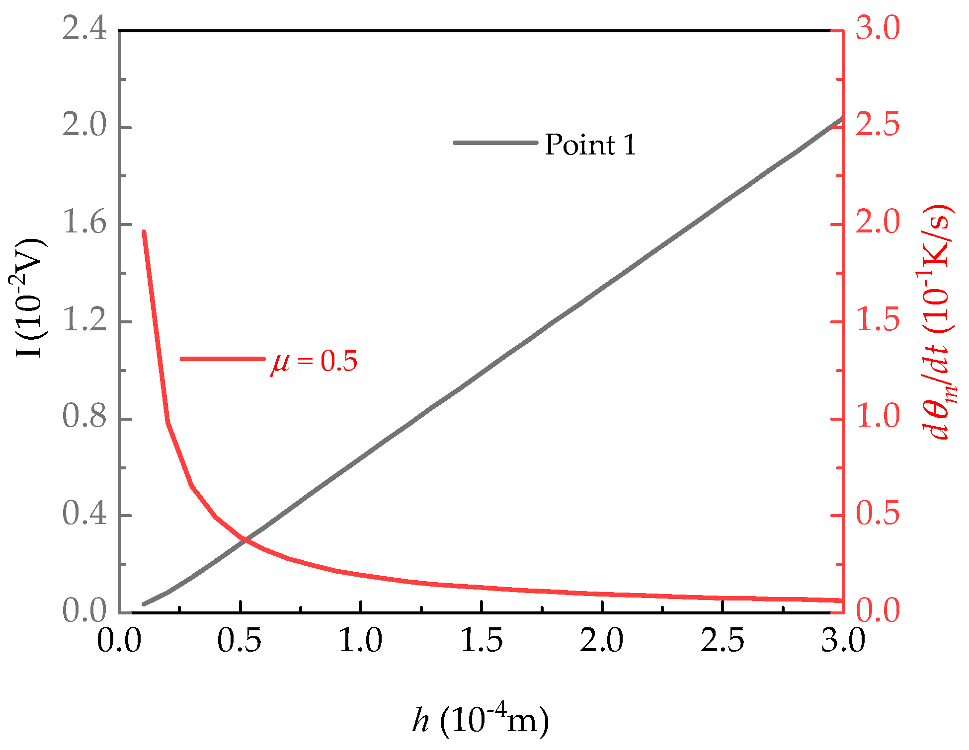
5. Optimization of Plate Thickness
6. Conclusions
- (1)
- The numerical results indicate that there is little influence of elastic boundary conditions on electric potential.
- (2)
- As temperature generated by the surface of a sensitive element increases, the influence of the piezoelectric property strengthens. However, the piezoelectric property can reduce the response electric potential of a pyroelectric plate.
- (3)
- A thicker plate results in a higher pyroelectric voltage, but it decreases the response speed of the detector response.
Author Contributions
Funding
Data Availability Statement
Conflicts of Interest
References
- Liu, S.T.; Long, D. Pyroelectric detectors and materials. Proc. IEEE 1978, 66, 14–26. [Google Scholar] [CrossRef]
- Zhou, L.; He, Y.; Zhang, Q.; Zhang, L. Carbon dioxide sensor module based on NDIR technology. Micromachines 2021, 12, 845. [Google Scholar] [CrossRef] [PubMed]
- Duan, Z.; Jiang, Y.; Tai, H. Recent advances in humidity sensors for human body related humidity detection. J. Mater. Chem. C 2021, 9, 14963–14980. [Google Scholar] [CrossRef]
- Li, C.; Tan, Q.; Zhang, W.; Xue, C.; Li, Y.; Xiong, J. Microfabrication of a novel ceramic pressure sensor with high sensitivity based on low-temperature co-fired ceramic (LTCC) technology. Micromachines 2014, 5, 396–407. [Google Scholar] [CrossRef]
- Kuo, J.T.; Yu, L.; Meng, E. Micromachined thermal flow sensors—A review. Micromachines 2012, 3, 550–573. [Google Scholar] [CrossRef]
- Smith, R.T.; Welsh, F.S. Temperature dependence of the elastic, piezoelectric, and dielectric constants of lithium tantalate and lithium niobate. J. Appl. Phys. 1971, 42, 2219–2230. [Google Scholar] [CrossRef]
- Evans, C.R.; Stanley, S.M.; Percival, C.J.; Mchale, G.; Newton, M.I. Lithium tantalate layer guided plate mode sensors. Sens. Actuators A-Phys. 2006, 132, 241–244. [Google Scholar] [CrossRef]
- Luo, J.; Luo, W.; Zhang, K.; Sun, X.; Shuai, Y.; Wang, T.; Wu, C.; Zhang, W. High specific detectivity infrared detector using crystal ion slicing transferred LiTaO3 single-crystal thin films. Sens. Actuators A-Phys. 2019, 300, 111650. [Google Scholar] [CrossRef]
- Agastra, A. Thermal Response of Lithium Tantalate for Temperature Measurement. Master’s Thesis, University of South Florida, Tampa, FL, USA, 2011. [Google Scholar]
- Zhang, K.; Luo, W.; Huang, S.; Bai, X.; Shuai, Y.; Zhao, Y.; Zeng, X.; Wu, C.; Zhang, W. Wavelength-selective infrared detector fabricated by integrating LiTaO3 with a metamaterial perfect absorber. Sens. Actuators A-Phys. 2020, 313, 112186. [Google Scholar] [CrossRef]
- D’Ottavio, M.; Polit, O. Sensitivity analysis of thickness assumptions for piezoelectric plate models. J. Intell. Mater. Syst. Struct. 2009, 20, 1815–1834. [Google Scholar] [CrossRef]
- Adelman, N.T.; Stavsky, Y. Flexural–extensional behavior of composite piezoelectric circular plates. J. Acoust. Soc. Am. 1980, 67, 819–822. [Google Scholar] [CrossRef]
- Fang, K.; Li, P.; Qian, Z. Static and Dynamic Analysis of a Piezoelectric Semiconductor Cantilever Under Consideration of Flexoelectricity and Strain Gradient Elasticity. Acta Mech. Solida Sin. 2021, 34, 673–686. [Google Scholar] [CrossRef]
- Luo, Y.X.; Cheng, R.R.; Zhang, C.L. Analysis of flexural vibrations of laminated piezoelectric semiconductor plates. Chin. J. Solid Mech. 2020, 41, 15–29. [Google Scholar]
- Qu, Y.; Jin, F.; Yang, J. Buckling of a Reissner–Mindlin plate of piezoelectric semiconductors. Meccanica 2022, 57, 2797–2807. [Google Scholar] [CrossRef]
- Reddy, J.N. A general non-linear third-order theory of plates with moderate thickness. Int. J. Non-Linear Mech. 1990, 25, 677–686. [Google Scholar] [CrossRef]
- Shi, G. A new simple third-order shear deformation theory of plates. Int. J. Solids Struct. 2007, 44, 4399–4417. [Google Scholar] [CrossRef]
- Touratier, M. An efficient standard plate theory. Int. J. Eng. Sci. 1991, 29, 901–916. [Google Scholar] [CrossRef]
- Wang, Q.; Quek, S.T.; Sun, C.T.; Liu, X. Analysis of piezoelectric coupled circular plate. Smart Mater. Struct. 2001, 10, 229. [Google Scholar] [CrossRef]
- Zhu, C.; Fang, X.; Liu, J.; Nie, G. Smart control of large amplitude vibration of porous piezoelectric conical sandwich panels resting on nonlinear elastic foundation. Compos. Struct. 2020, 246, 112384. [Google Scholar] [CrossRef]
- Fernandes, A.; Pouget, J. Two-dimensional modelling of laminated piezoelectric composites: Analysis and numerical results. Thin-Walled Struct. 2001, 39, 3–22. [Google Scholar] [CrossRef]
- Lian, M.M.; Fan, C.Y.; Qin, G.S.; Lu, C.S.; Wang, B.B.; Zhao, M.H. A modified first-order plate theory of laminated piezoelectric plate actuators. Eur. J. Mech. A-Solids 2024, 104, 105209. [Google Scholar] [CrossRef]
- Aleks, M.; Jagtap, C.; Kadam, V.; Kolev, G.; Denishev, K.; Pathan, H. An overview of microelectronic infrared pyroelectric detector. Eng. Sci. 2021, 16, 82–89. [Google Scholar]
- Zhao, L.; He, X.; Li, J.; Gao, X.; Jia, J. Electrosprayed carbon-based black coatings for pyroelectric detectors. Sens. Actuators A-Phys. 2013, 196, 16–21. [Google Scholar] [CrossRef]
- Zhang, T.Y.; Qian, C.F.; Tong, P. Linear electro-elastic analysis of a cavity or a crack in a piezoelectric material. Int. J. Solids Struct. 1998, 35, 2121–2149. [Google Scholar] [CrossRef]
- Qu, Y.L.; Jin, F.; Yang, J.S. Temperature effects on mobile charges in thermopiezoelectric semiconductor plates. Int. J. Appl. Mech. 2021, 13, 2150037. [Google Scholar] [CrossRef]
- Lehman, J.; Theocharous, E.; Eppeldauer, G.; Pannell, C. Gold-black coatings for freestanding pyroelectric detectors. Meas. Sci. Technol. 2003, 14, 916. [Google Scholar] [CrossRef]
- Sakamoto, W.K.; Shibatta-Kagesawa, S.T.; Melo, W. Voltage responsivity of pyroelectric sensor. Sens. Actuators A-Phys. 1999, 77, 28–33. [Google Scholar] [CrossRef]
- Patrashin, A.I.; Nikonov, A.V.; Kovshov, V.S. Generalized Method for Calculating Irradiance from a Black Body. J. Commun. Technol. Electron. 2020, 65, 326–331. [Google Scholar] [CrossRef]
- Ali, Y.M.; Zhang, L.C. Relativistic heat conduction. Int. J. Heat Mass Transf. 2005, 48, 2397–2406. [Google Scholar] [CrossRef]
- Bowen, C.R.; Taylor, J.; Le Boulbar, E.; Zabek, D.; Topolov, V.Y. A modified figure of merit for pyroelectric energy harvesting. Mater. Lett. 2015, 138, 243–246. [Google Scholar] [CrossRef]
- Cheng, J. Research on Sensitive Element for Pyroelectric Detector Based on Lithium Tantalate Wafer. Master’s Thesis, University of Electronic Science and Technology of China, Chengdu, China, 2017. [Google Scholar]
- Suen, J.Y.; Fan, K.; Montoya, J.; Bingham, C.; Stenger, V.; Sriram, S.; Padilla, W.J. Multifunctional metamaterial pyroelectric infrared detectors. Optica 2017, 4, 276–279. [Google Scholar] [CrossRef]


| Elastic Stiffness (1010 N m−2) | Piezoelectric Constant (C m−2) | Dielectric Constant (10−10 F m−1) | Pyroelectric Coefficient (10−4 C m−2 K−1) | Thermal Conductivity (W m−1 K−1) |
|---|---|---|---|---|
| c1111 = 23.30 | e113 = 0.08 | κ11 = 3.61 | p1 = −2.3 | β1 = 46 |
| c1122 = 4.69 | e333 = 1.88 | κ33 = 3.83 | p3 = −2.3 | β3 = 46 |
| c1133 = 8.02 | e311 = 2.30 | |||
| c3333 = 27.54 |
| Supported State | Present Theory | FEM | Upper Surface Error (%) | Median Plane Error (%) | ||
|---|---|---|---|---|---|---|
| Point 1 Potential (10−3 V) | Point 2 Potential (10−3 V) | Point 1 Potential (10−3 V) | Point 2 Potential (10−3 V) | |||
| Four-side clamped | −6.39 | −1.80 | −6.61 | −1.85 | −3.32 | −2.70 |
| Four-side simply supported | −6.39 | −1.81 | −6.66 | −1.88 | −4.05 | −3.72 |
| Two-side clamped | −6.39 | −1.80 | −6.64 | −1.87 | −3.77 | −3.74 |
| Four-point simply supported | −6.46 | −1.84 | −6.71 | −1.91 | −3.72 | −3.66 |
| Parameter | Symbol | Value | Unit |
|---|---|---|---|
| Modulation factor | α | 0.5 | – |
| Effective emissivity | δ | 0.99 | – |
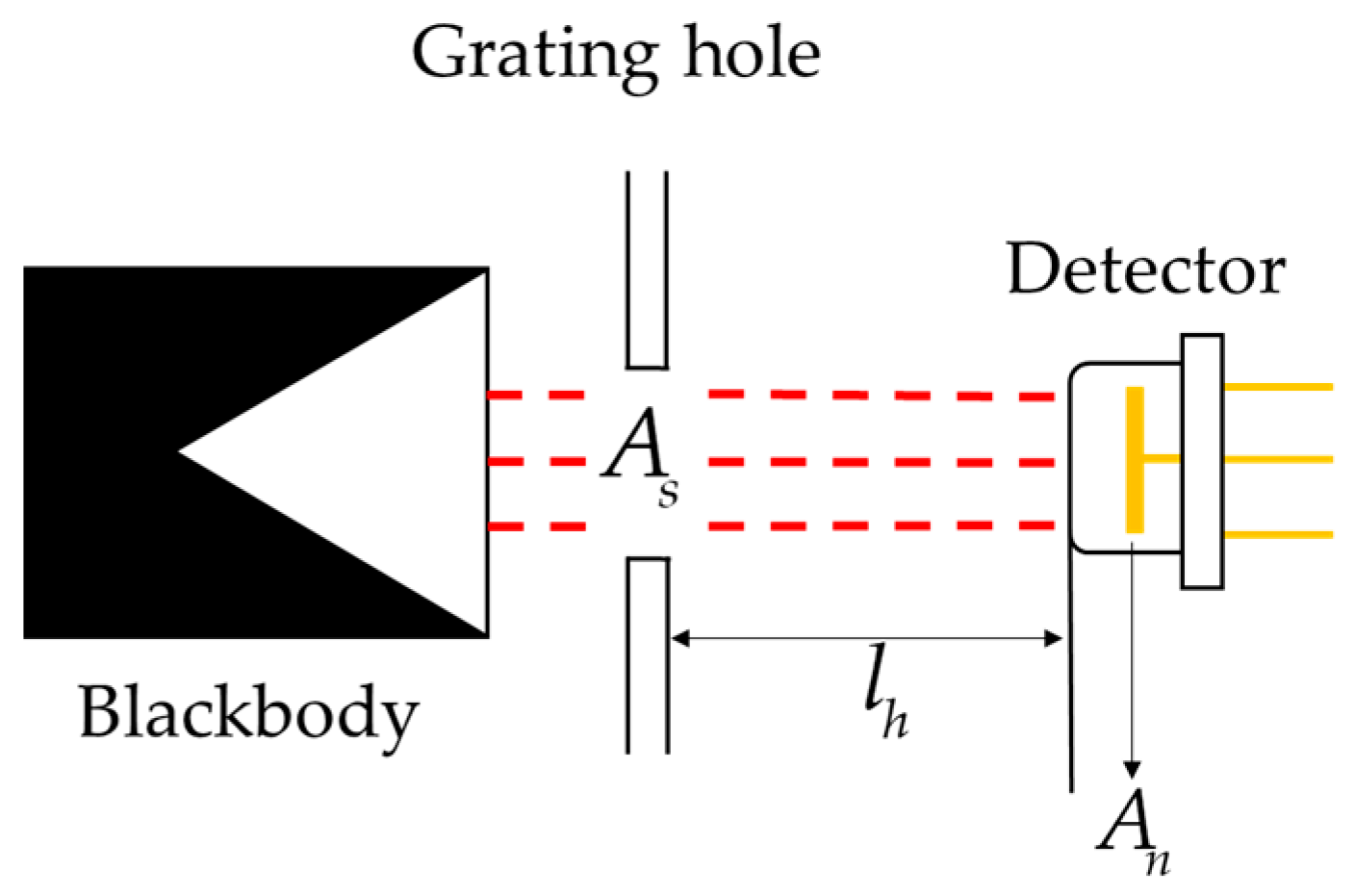
| The distance between light and detector | lh | 0.1 | m |
| Grating area | As | 7.9 × 10⁻⁵ | m2 |
| Heat capacity at constant pressure | c | 250 | J kg−1 K−1 |
| Density | ρ | 7450 | kg m−3 |
| Stefan–Boltzmann constant | St | 5.67 × 10⁻⁸ | W m−2 K−4 |
| Blackbody temperature | θH | 500 | K |
| Ambient temperature | θ0 | 293.15 | K |
Disclaimer/Publisher’s Note: The statements, opinions and data contained in all publications are solely those of the individual author(s) and contributor(s) and not of MDPI and/or the editor(s). MDPI and/or the editor(s) disclaim responsibility for any injury to people or property resulting from any ideas, methods, instructions or products referred to in the content. |
© 2024 by the authors. Licensee MDPI, Basel, Switzerland. This article is an open access article distributed under the terms and conditions of the Creative Commons Attribution (CC BY) license (https://creativecommons.org/licenses/by/4.0/).
Share and Cite
Lian, M.; Fan, C.; Zhan, X.; Zhao, M.; Qin, G.; Lu, C. Application of a Modified First-Order Plate Theory to Structural Analysis of Sensitive Elements in a Pyroelectric Detector. Micromachines 2024, 15, 1012. https://doi.org/10.3390/mi15081012
Lian M, Fan C, Zhan X, Zhao M, Qin G, Lu C. Application of a Modified First-Order Plate Theory to Structural Analysis of Sensitive Elements in a Pyroelectric Detector. Micromachines. 2024; 15(8):1012. https://doi.org/10.3390/mi15081012
Chicago/Turabian StyleLian, Mengmeng, Cuiying Fan, Xiaohan Zhan, Minghao Zhao, Guoshuai Qin, and Chunsheng Lu. 2024. "Application of a Modified First-Order Plate Theory to Structural Analysis of Sensitive Elements in a Pyroelectric Detector" Micromachines 15, no. 8: 1012. https://doi.org/10.3390/mi15081012