
Series/Parallel Switching for Increasing Power Extraction from Thermoelectric Power Generators


Abstract
:
1. Introduction
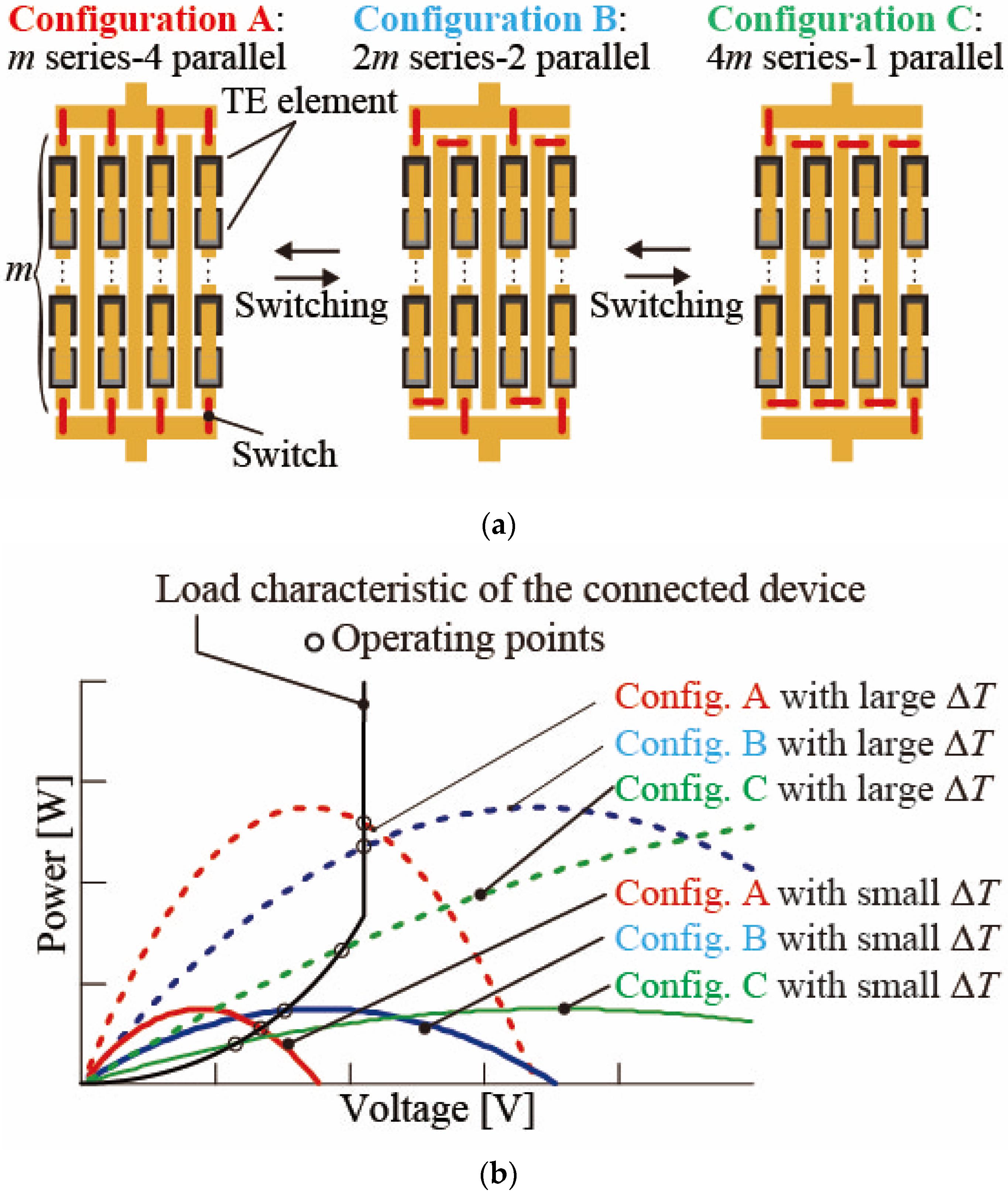
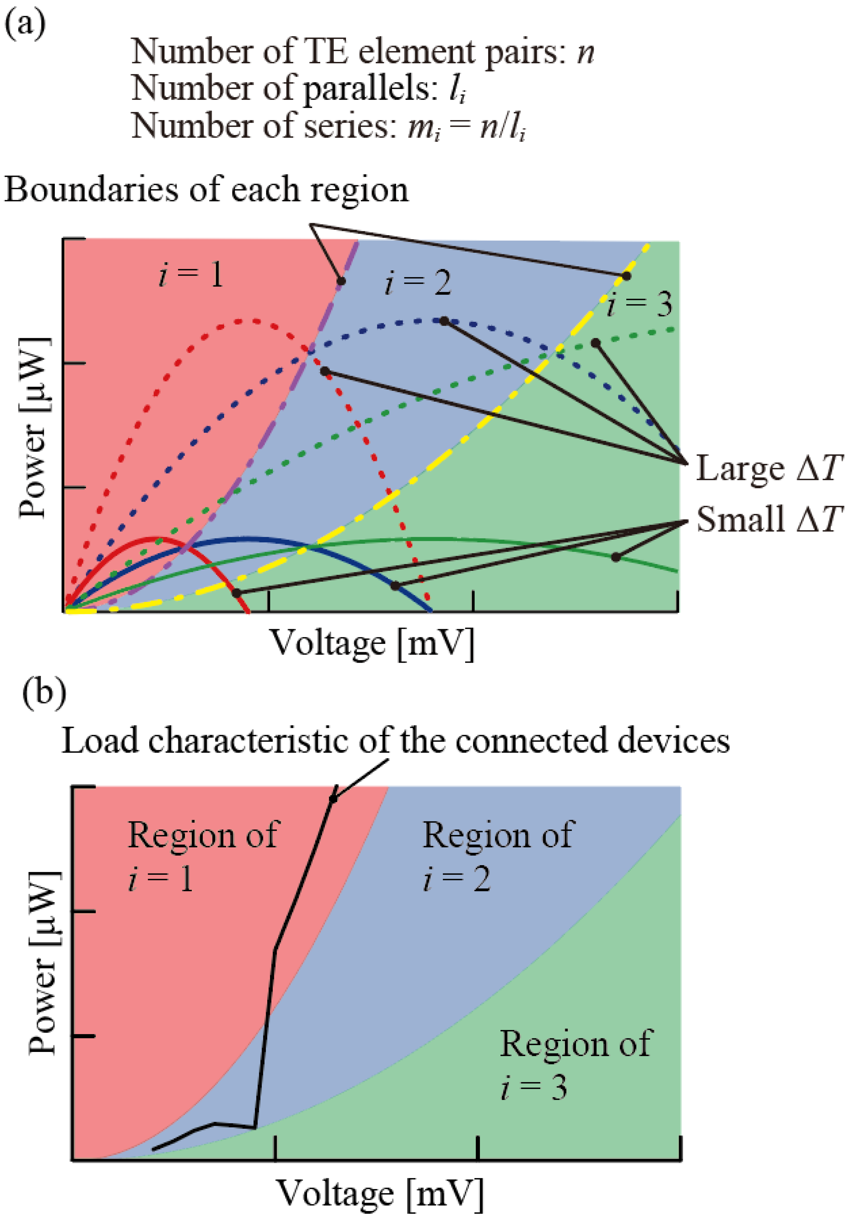
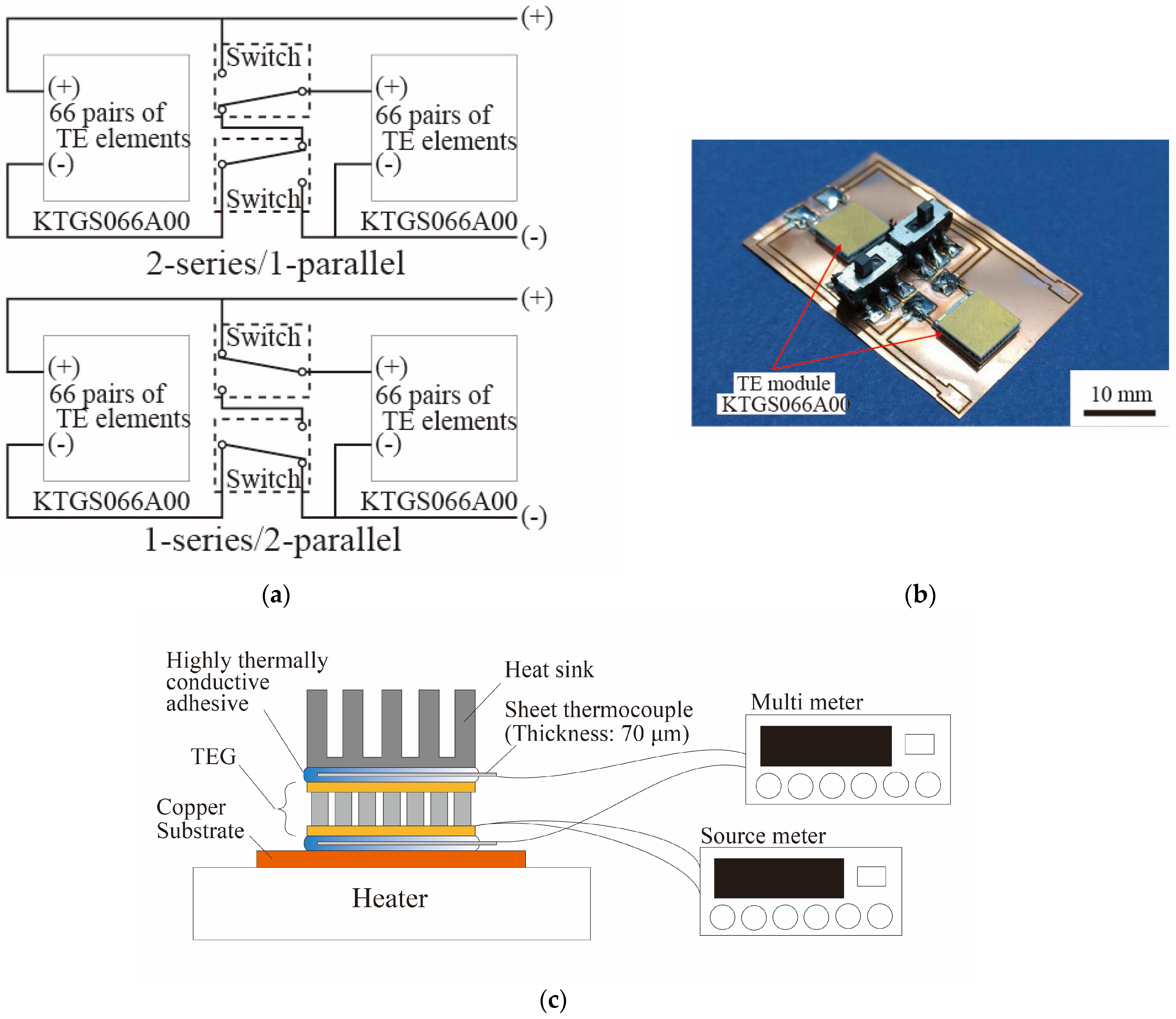
2. Design
3. Effect on Extracted Power of Switching Circuit Configuration
4. Conclusions
Author Contributions
Funding
Data Availability Statement
Acknowledgments
Conflicts of Interest
References
- Lapena, O.L.; Penella, M.T.; Gasulla, M. A New MPPT Method for Low-Power Solar Energy Harvesting. IEEE Trans. Ind. Electron. 2010, 57, 3129–3138. [Google Scholar] [CrossRef]
- Edla, M.; Lim, Y.Y.; Padilla, R.V.; Deguchi, M. An Improved Rectifier Circuit for Piezoelectric Energy Harvesting from Human Motion. Appl. Sci. 2021, 11, 2008. [Google Scholar] [CrossRef]
- Liu, H.; Fu, H.; Sun, L.; Lee, C.; Yeatman, E.M. Hybrid energy harvesting technology: From materials, structural design, system integration to applications. Renew. Sustain. Energy Rev. 2021, 137, 110473. [Google Scholar] [CrossRef]
- Harasa, M.; Skotnicki, T. Thermoelectricity for IoT—A review. Nano Energy 2018, 54, 461–476. [Google Scholar] [CrossRef]
- Chen, Z.G.; Shi, X.; Zhao, L.D.; Zou, J. High-performance SnSe thermoelectric materials: Progress and future challenge. Prog. Mater. Sci. 2018, 97, 283–346. [Google Scholar] [CrossRef]
- Yang, Q.; Yang, S.; Qiu, P.; Peng, L.; Wei, T.R.; Zhang, Z.; Shi, X.; Chen, L. Flexible thermoelectrics based on ductile semiconductors. Science 2022, 377, 854–858. [Google Scholar] [CrossRef] [PubMed]
- Liu, W.; Jie, Q.; Kim, H.S.; Ren, Z. Current progress and future challenges in thermoelectric power generation: From materials to devices. Acta Mater. 2015, 87, 357–376. [Google Scholar] [CrossRef]
- Bharti, M.; Singh, A.; Samanta, S.; Aswal, D.K. Conductive polymers for thermoelectric power generation. Prog. Mater. Sci. 2018, 93, 270–310. [Google Scholar] [CrossRef]
- Suemori, K.; Hoshino, S.; Kamata, T. Flexible and Lightweight Thermoelectric Generators Composed of Carbon Nanotube-Polystyrene Composites Printed on Film Substrate. Appl. Phys. Lett. 2013, 103, 153902. [Google Scholar] [CrossRef]
- Sugahara, T.; Ekubaru, Y.; Nong, N.V.; Kagami, N.; Ohata, K.; Hung, L.T.; Okajima, M.; Nambu, S.; Suganuma, K. Fabrication with Semiconductor Packaging Technologies and Characterization of a Large-Scale Flexible Thermoelectric Module. Adv. Mater. Technol. 2019, 4, 1800556. [Google Scholar] [CrossRef]
- Petsagkourakis, I.; Tybrandt, K.; Crispin, X.; Ohkubo, I.; Satoh, N.; Mori, T. Thermoelectric Materials and Applications for Energy Harvesting Power Generation. Sci. Technol. Adv. Mater. 2018, 19, 836–862. [Google Scholar] [CrossRef]
- Liu, X.; Du, Y.; Meng, Q.; Shen, S.Z.; Xu, J. Flexible Thermoelectric Power Generators Fabricated Using Graphene/PEDOT:PSS Nanocomposite Films. J. Mater. Sci. Mater. Electron. 2019, 30, 20369–20375. [Google Scholar] [CrossRef]
- Lossec, M.; Multon, B.; Ben Ahmed, H.; Goupil, C. Thermoelectric Generator Placed on The Human Body: System Modeling and Energy Conversion Improvements. EPJ Appl. Phys. 2010, 52, 11103. [Google Scholar] [CrossRef]
- Li, C.; Jiang, F.; Liu, C.; Liu, P.; Xu, J. Present and Future Thermoelectric Materials toward Wearable Energy Harvesting. Appl. Mater. Today 2019, 15, 543–557. [Google Scholar] [CrossRef]
- Mita, K. Development of Thermal Interface Materials for IT-Related Applications (Silicone type TIM). Nippon Gomu Kyokaishi 2011, 78, 153–157. [Google Scholar] [CrossRef]
- Hunter, M.A. Light Emitting Diode Light Strip. U.S. Patent 6,283,612 B1, 13 March 2000. [Google Scholar]
- Jeong, S.H.; Cruz, F.J.; Chen, S.; Gravier, L.; Liu, J.; Wu, Z.; Hjort, K.; Zhang, S.-L.; Zhang, Z.-B. Stretchable Thermoelectric Generators Metallized with Liquid Alloy. ACS Appl. Mater. Interfaces 2017, 9, 15791–15797. [Google Scholar] [CrossRef] [PubMed]
- Kim, S.J.; We, J.H.; Cho, B.J. A Wearable Thermoelectric Generator Fabricated on a Glass Fabric. Energy Environ. Sci. 2014, 7, 1959–1965. [Google Scholar] [CrossRef]
- Bautista, S.C.; Eladawy, A.; Mohieldin, A.N.; Sinencio, E.S. Boost Converter with Dynamic Input Impedance Matching for Energy Harvesting with Multi-Array Thermoelectric Generators. IEEE Trans. Ind. Electron. 2014, 61, 5345–5352. [Google Scholar] [CrossRef]
- Jaziri, N.; Boughamoura, A.; Müller, J.; Mezghani, B.; Tounsi, F.; Ismail, M. A comprehensive review of Thermoelectric Generators: Technologies and common applications. Energy Rep. 2020, 6, 264–287. [Google Scholar] [CrossRef]
- Chen, Y.; Yang, B.; Guo, Z.; Wang, J.; Zhu, M.; Li, Z.; Yu, T. Dynamic reconfiguration for TEG systems under heterogeneous temperature distribution via adaptive coordinated seeker. Prot. Control. Mod. Power Syst. 2022, 7, 38. [Google Scholar] [CrossRef]
- Patra, S.; Muthe, K.P.; Prakash, D.; Singh, A. Low-Voltage Self-Operating MPPT Controlled Boost Converter for Thermoelectric Power Generator. IEEE J. Emerg. Sel. Top. Ind. Electron. 2023, 4, 1045–1054. [Google Scholar] [CrossRef]
- Bijukumar, B.; Chakkarapani, M.; Ganesan, S.I. On the Importance of Blocking Diodes in Thermoelectric Generator Arrays and Their Effect on MPPs under Temperature Mismatch Conditions. IEEE Trans. Energy Convers. 2023, 38, 2730–2743. [Google Scholar] [CrossRef]


| 2-Series/1-Parallel | 1-Series/2-Parallel | |
|---|---|---|
| ΔT = 3.0 K | OPS1: 195 ± 1.3 µW | OPP1: 177 ± 1.6 µW |
| ΔT = 4.0 K | OPS2: 283 ± 1.5 µW | OPP2: 348 ± 2.2 µW |
| 2-Series/1-Parallel | 1 Series/2 Parallel | |
|---|---|---|
| ΔT = 3.0 K | t1: 69.7 s, t2: 30.6 s | t1: 78.2 s, t2: 32.4 s |
| ΔT = 4.0 K | t1: 66.5 s, t2: 27.6 s | t1: 65.7 s, t2: 27.0 s |
Disclaimer/Publisher’s Note: The statements, opinions and data contained in all publications are solely those of the individual author(s) and contributor(s) and not of MDPI and/or the editor(s). MDPI and/or the editor(s) disclaim responsibility for any injury to people or property resulting from any ideas, methods, instructions or products referred to in the content. |
© 2024 by the authors. Licensee MDPI, Basel, Switzerland. This article is an open access article distributed under the terms and conditions of the Creative Commons Attribution (CC BY) license (https://creativecommons.org/licenses/by/4.0/).
Share and Cite
Terashima, S.; Sorimachi, R.; Iwase, E. Series/Parallel Switching for Increasing Power Extraction from Thermoelectric Power Generators. Micromachines 2024, 15, 1015. https://doi.org/10.3390/mi15081015
Terashima S, Sorimachi R, Iwase E. Series/Parallel Switching for Increasing Power Extraction from Thermoelectric Power Generators. Micromachines. 2024; 15(8):1015. https://doi.org/10.3390/mi15081015
Chicago/Turabian StyleTerashima, Shingo, Ryuji Sorimachi, and Eiji Iwase. 2024. "Series/Parallel Switching for Increasing Power Extraction from Thermoelectric Power Generators" Micromachines 15, no. 8: 1015. https://doi.org/10.3390/mi15081015
APA StyleTerashima, S., Sorimachi, R., & Iwase, E. (2024). Series/Parallel Switching for Increasing Power Extraction from Thermoelectric Power Generators. Micromachines, 15(8), 1015. https://doi.org/10.3390/mi15081015