Article

Switchable Vanadium Dioxide Metasurface for Terahertz Ultra-Broadband Absorption and Reflective Polarization Conversion

1
Department of Physics, School of Physics and Material Science, Nanchang University, Nanchang 330031, China
2
Institute of Space Science and Technology, Nanchang University, Nanchang 330031, China
3
School of Physics, Nankai University, Tianjin 300071, China
4
Collaborative Innovation Center of Extreme Optics, Shanxi University, Taiyuan 030006, China
*
Authors to whom correspondence should be addressed.
Micromachines 2024, 15(8), 967; https://doi.org/10.3390/mi15080967 (registering DOI)
Submission received: 26 June 2024 / Revised: 24 July 2024 / Accepted: 26 July 2024 / Published: 28 July 2024
(This article belongs to the Special Issue Recent Advances in Terahertz Devices and Applications)

Abstract

:
Based on the unique insulator-metal phase transition property of vanadium dioxide (VO2), we propose an integrated metasurface with a switchable mechanism between ultra-broadband absorption and polarization conversion, operating in the terahertz (THz) frequency range. The designed metasurface device is constructed using a stacked structure composed of VO2 quadruple rings, a dielectric layer, copper stripes, VO2 film, a dielectric layer, and a copper reflection layer. Our numerical simulations demonstrate that our proposed design, at high temperatures (above 358 K), exhibits an ultra-broadband absorption ranging from 4.95 to 18.39 THz, maintaining an absorptivity greater than 90%, and achieves a relative absorption bandwidth of up to 115%, significantly exceeding previous research records. At room temperature (298 K), leveraging VO2’s insulating state, our proposed structure transitions into an effective polarization converter, without any alteration to its geometry. It enables efficient conversion between orthogonal linear polarizations across 3.51 to 10.26 THz, with cross-polarized reflection exceeding 90% and a polarization conversion ratio over 97%. More importantly, its relative bandwidth reaches up to 98%. These features highlight its wide-angle, extensive bandwidth, and high-efficiency advantages for both switching functionalities. Such an ultra-broadband convertible design offers potential applications in optical switching, temperature dependent optical sensors, and other tunable THz devices in various fields.

1. Introduction

Recently, metasurfaces [1,2,3,4,5,6] have gained widespread interest for their ability to freely manipulate the amplitude, phase, and polarization of electromagnetic waves at the sub-wavelength scale, because of the appealing advantages including compactness, flexibility, broad bandwidth, and easy integration [7,8,9,10]. At THz wavelengths, metasurfaces can exhibit a range of distinctive properties that are useful in developing various functional devices, such as beam splitters, biosensors, filters, polarization converters, optical switches [11,12,13,14], and absorbers [15,16,17,18,19]. Conventional metasurfaces are constructed from metallic or dielectric materials with dimensions much smaller than the wavelength of operation, which allows the subwavelength structures to alter the polarization, phase, amplitude, and frequency of electromagnetic waves. However, the characteristics of traditional metasurfaces are generally fixed post-manufacture. To create flexible THz metasurfaces, active materials such as graphene [20,21,22], VO2 [23,24,25], Ge2Sb2Te5(GST) [26,27], and photoconductive semiconductors [28,29] have been integrated into traditional metasurfaces, significantly enhancing their tunability. Notably, graphene stands out owing to its dynamically adjustable carrier mobility and conductivity [30,31,32]. A switchable broadband absorber and reflector was developed using a hybrid graphene-gold metasurface, achieving high absorption from 0.53 to 1.05 THz over wide incidence angles [33]. VO2 is renowned for its unique metal-insulator phase transition characteristics and has extraordinary appeal in THz applications, which has led to its application in the development of thermally tunable metasurfaces, marking significant progress in this field [34,35,36]. Moreover, among the aforementioned phase-change materials, VO2 stands out as a distinctive material, featuring multiple modulation modes such as electrical, thermal, or optical excitation, with an extremely short response time (approximately 100 fs) and a remarkable modulation depth. This is mainly attributed to the fact that when the temperature climbs to approximately 358 K, its structural phase transforms from the monoclinic phase to the tetragonal phase, causing a substantial change in the dielectric constant. Incorporating VO2 into THz metasurfaces allows for the creation of adjustable multifunctional devices, significantly impacting the development of THz technology. For example, the concurrent absorption and polarization conversion functionalities can enhance THz imaging and sensing techniques, while the wavefront manipulation can facilitate beam steering and shaping in THz communication and imaging systems [37,38].
A wide operation bandwidth is always desired for effective performance in practical applications. Broadband absorption, for instance, is crucial for solar energy capture and light detection, achievable through the layering of structures with differing absorption characteristics or the amalgamation of materials with various absorption mechanisms. Reports have emerged of a broadband switchable THz half-/quarter-wave plate based on metal-VO2 metamaterials, demonstrating dual functionality within 0.66 to 1.44 THz range [39]; furthermore, a transition from a broadband perfect absorber to a broadband polarization converter has been achieved, with bifunctionality spanning 0.52 THz to 1.04 THz [40]; additionally, another actively switchable VO2 metasurface has been engineered for concurrent absorption and polarization conversion switching, effectively manipulating the functionalities from 1.41 to 2.69 THz [41]. With the increasing demands in integrated and multifunctional devices, broadband switching phenomena are highly desirable and promising, but still challenging in the THz range.
In this study, an ultra-broadband versatile THz metasurface device is proposed by designing a stacked structure. By utilizing the phase-change capabilities of VO2, the device can switch between broad-spectrum absorption and polarization conversion. For the absorption mode corresponding to VO2 in the metallic state, the device achieves an ultra-broadband absorption across 4.95 to 18.39 THz, with absorption greater than 90%. For the polarization conversion mode corresponding to VO2 in the insulating state, it acts as a polarization converter within 3.51 to 10.26 THz, with more than 90% efficiency in cross-polarized reflection. Additionally, we carried out numerical simulations to investigate the effects of the polarization, incident angle, and the device geometry on the versatile device. This structure outshines previous switchable metasurfaces by offering ultra-broadband capabilities, wide-angle functionality, efficient conversion, and polarization-sensitive absorption, holding great promise in optical communications, THz polarization sensors, optical switching, and beyond.

2. Structure Design and Numerical Method

We consider the quadruple ring in our metasurface design to realize a polarization-independent THz absorber with VO2 in insulating state. Periodic oblique copper (Cu) stripes are placed in the middle of the stacked structure to play an important role in the polarization conversion when VO2 stays in a fully metallic state at room temperature. The 3D structure for the proposed design and its unit cell are schematically depicted in Figure 1a and Figure 1b, respectively, which consists of six layers from top to bottom: the VO2 quadruple ring, a dielectric layer, Cu stripes, VO2 film, a dielectric layer, and a Cu reflection layer. The corresponding geometric parameters are presented in the caption of Figure 1b–d. To effectively optimize the proposed structure design, we employ the finite-difference time-domain (FDTD) method to explore its electromagnetic response. Since the proposed design is periodic in the x and y directions, we simulate just one unit cell numerically to speed up both the operation and analysis. Periodic boundary conditions are used along the x and y directions, with open boundary conditions along the z direction to generate incident wave on the structure. Through rigorous optimization, the period along the x and y directions is fixed at P = 20 μm, with the dielectric layer thickness being h1 = 7.4 μm, h2 = 5 μm. Additionally, the thicknesses of the Cu reflection layer and the VO2 film are t1 = 0.2 μm and t2 = 0.1 μm, respectively. Figure 1c illustrates the parameter of the VO2 quadruple ring, with outer and inner radii R = 4 μm and r = 3 μm, respectively. The distance from the center to the border is D = 6 μm. From Figure 1d, it can be seen that the Cu stripes are positioned at an angle of 45° relative to the x-axis, each having a length of L = 18 μm, a width of d = 2 μm, a spacing between the two strips of w1 = 5.35 μm, and a thickness of t4 = 0.1 μm. These parameters are fixed unless stated otherwise.
In the THz frequency range, the relative permittivity of VO2 can be described with the Drude model [42,43,44,45]:
ε VO 2 ( ω ) = ε ω p 2 ω ( ω + i γ )
where ω p is the plasma frequency, calculated by ω p 2 = ω p 0 2 σ / σ 0 . The initial value of the plasma frequency is ω p 0 = 1.45 × 10 15   rad / s , σ 0 = 3 × 10 5   S / m . Here, ε = 12 is the dielectric permittivity in the infinite frequency, and the collision frequency γ = 5.75 × 10 13   rad / s . Given that the conductivity σ is proportional to the free space carrier density, it fluctuates with the phase change of the VO2 film. In our numerical simulations, we adjust the conductivity values to reflect the VO2 material’s varying states. In this study, it is important to note that we only examine the fully metallic and fully insulating states of VO2 in order to achieve switchable functionalities of the proposed structure. Specifically, when the VO2 is in its metallic state, it possesses a conductivity of 2 × 10⁵ S/m, and when in the insulator state, its conductivity is 10 S/m. The dielectric layer consists of a depleted polymer with a relative dielectric constant of ε = 1.5 + 0.005i. The material Cu is set as a lossy metal with an electrical conductivity of 5.8 × 10⁷ S/m.

3. Results and Discussion

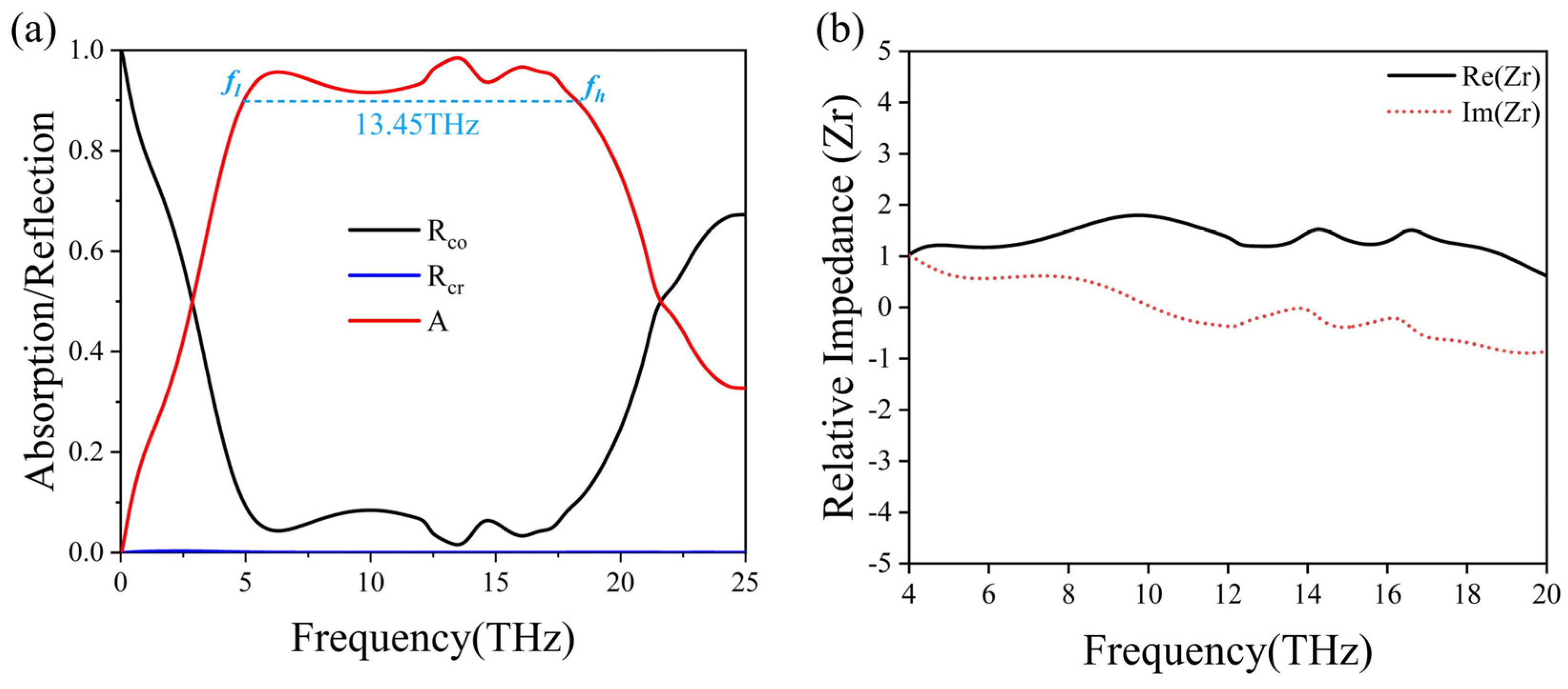
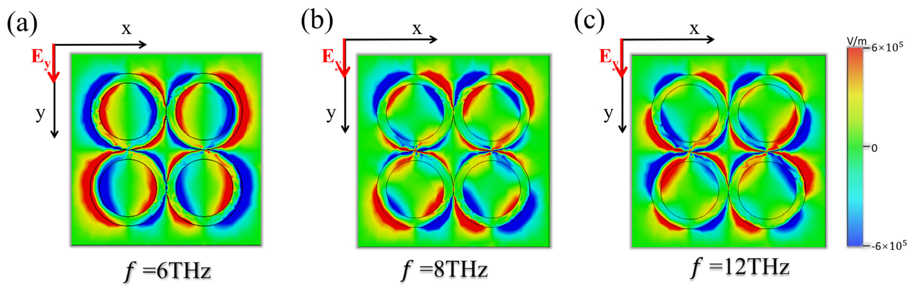
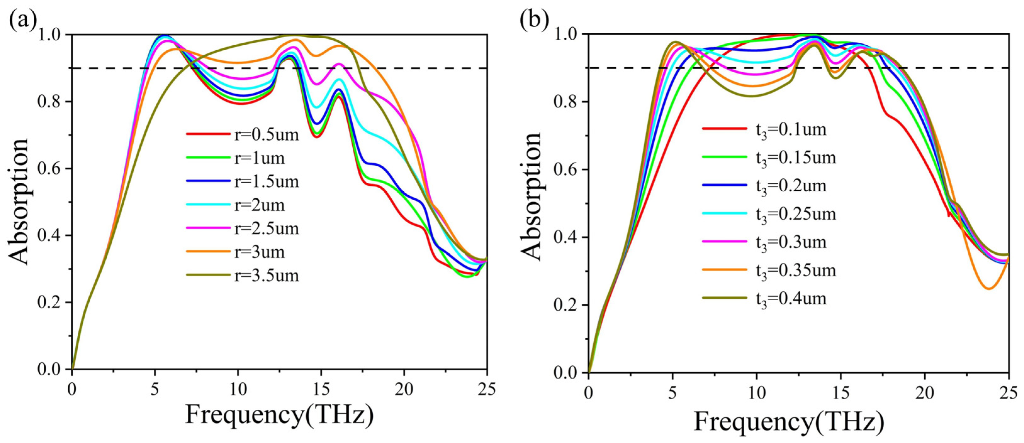
3.1. Ultra-Broadband Absorption with the VO2 Metasurface Structure

In order to verify the performance of the proposed structure, we investigate the configuration shown in Figure 1 by employing numerical simulations. The electric field of the incident electromagnetic wave is polarized along the y-axis. We first calculate the absorption spectra when VO2 quadruple ring and VO2 film are in a completely metallic state. The absorption of the proposed structure can be obtained by A = 1 − R − T, where R and T are the computed reflection and transmission, respectively. The continuous VO2 film remains in its metallic state, acting as a reflective ground plane, and effectively prevents any transmission. As a result, the absorption can be computed with A = 1 − R. Here, the cross- and co-polarized reflection, i.e., Rcr and Rco, are also demonstrated for comparison with the results from the polarization conversion function (see details in the next subsection). The simulated spectra are presented in Figure 2a, as a function of frequency. It can be clearly observed that 90 % absorption is achieved in a broad frequency range from 4.95 to 18.4 THz. The relative absorption bandwidth (RAB) is defined to enable an effective comparison of bandwidth characteristics, expressed as RAB = 2 × ( f h f l ) / ( f h + f l ) , where fh and fl are the upper and lower frequency bounds, respectively, corresponding to frequencies at which the absorption exceeds 90%. Understanding the definition of RAB is crucial for making accurate bandwidth comparisons across different operational frequencies. By calculation, it is determined that the structure’s RAB can achieve up to 115.2% when VO2 is fully in a metallic state, indicating that this metasurface design functions as an effective absorber over a wide frequency range in the THz spectrum.
To thoroughly comprehend the absorption mechanism of the proposed structure, we utilize the impedance matching theory [46,47]. According to the theory, the absorption of the structure can be calculated by using A = 1 | ( Z Z 0 ) / ( Z + Z 0 ) | 2 , where Z0 is the free space impedance, and Z is the effective impedance of the proposed structure, described as Z = μ 1 / ε 1 , where μ 1 and ε 1 stand for the effective permeability and permittivity, respectively. The absorption formula can be simplified to A = 1 | ( Z r 1 ) / ( Z r + 1 ) | 2 by utilizing the relative impedance Z r = Z / Z 0 , which can be computed with S-parameters from our numerical simulations, Z r = ( ( 1 + S 11 ) 2 S 21 2 ) / ( ( 1 S 11 ) 2 S 21 2 ) . In a two-port network, S11 represents the reflection at port 1 when the incident wave enters port 1, and S21 represents the transmission from port 1 to port 2. As a result, S11 and S22 are the reflection and transmission coefficients of the incident electromagnetic wave. The simplified formulae indicate that complete absorption can be realized when the relative impedance is near 1, meaning that the structure’s impedance should match to the free space impedance. The broadband absorption is confirmed in Figure 2b through the calculation of the real and imaginary parts of the relative impedance of the structure. It is evident that the real and imaginary parts of the absorber’s relative impedance are approximately 1 and 0, respectively, across a wide frequency range. This clearly demonstrates the successful achievement of impedance matching between the proposed structure and the free space.
We further illustrate the fundamental mechanism of broadband absorption by calculating the electric field intensity distribution of the structure. Figure 3 depicts the field distribution with y-polarization incidence on the structure. We have selected three frequencies (6 THz, 8 THz, and 12 THz) to aid in analyzing the broadband mechanism of the absorption spectrum. Upon observing the corresponding Ez components at these resonances, we find that the incident energy is localized along the VO2 ring in all the cases. At the resonance frequency f1 = 6 THz, the length of one ring in the structure is approximately equal to half the wavelength of the electromagnetic field, and electric dipole resonance manifests in each ring, as shown in Figure 3a, which explains the high absorption at this frequency. At frequencies f2 = 8 THz and f3 = 12 THz, the length of one ring in the structure is approximately equal to two half-waves of the electromagnetic field, and quadrupole resonance occurs in each ring, contributing to a high absorption, as depicted in Figure 3b,c, respectively. It is important to mention that in the proposed stacked structure, the broadband absorption is not affected by polarization of incident waves, thanks to the symmetry of the structure. The simulated results are presented in Figure 4a, where absorption contour plots are calculated as a function of frequency and polarization angles. The absorption remains its peak value between 4.95 and 18.4 THz regardless of the polarization.
Next, we investigate the performance of the proposed absorber for different incident angles of the excitation wave. The ability to deal with wide incident angles is a critical criterion for assessing absorbers. The calculated absorption is shown in Figure 4b as a function of the incident angle and operation frequencies. It is evident that the absorption bandwidth remains wide when the incident angle is below 50°, and the absorption can reach a high value of 93.2% with the incident angle being 70°. However, the absorption bandwidth gradually decreases when the incident angle is beyond the 50° threshold. Importantly, the 90 % absorption bandwidth can reach up to 5.1 THz even though the incident angle is as high as 60°. These findings illustrate that the proposed design is capable of attaining high-efficiency absorption along with broad-angle and extensive bandwidth features.
We further consider how the broadband absorption spectrum varies with the structure’s geometrical features. Based on the initial analysis (structure design and field distribution), we have determined that the quadruple VO2 ring plays a crucial role in achieving complete absorption. As a result, our focus is on the thickness and the inner radius of the VO2 ring positioned atop the metasurface structure. Figure 5a illustrates the effect of the inner radius r on the absorption spectra. It is found that as the radius r increases from 0.5 μm to 3.5 μm, the 90 % absorption gradually transitions from multiple peaks to a single peak, with the first peak diminishing gradually. The maximum bandwidth ( 90 % ) is achieved at r = 3 μm, culminating in a perfect absorption with a single peak at 3.5 μm. In Figure 5b, we calculate the absorption spectra with different thickness t3 of the VO2 ring. It can be seen that as t3 increases from 0.1 μm to 0.4 μm, the maximum absorption decreases from 100% to 90%. Simultaneously, the absorption bandwidth increases until t3 reaches 0.25 μm. At around 10 THz, the absorption of the structure starts to decline as the thickness of the VO2 ring increases, resulting in the loss of the broad absorption characteristics. To conclude, the parameters of the VO2 ring are important for the achievement of its broadband absorption. Therefore, careful consideration of the structure’s geometry is essential for future experimental verification.

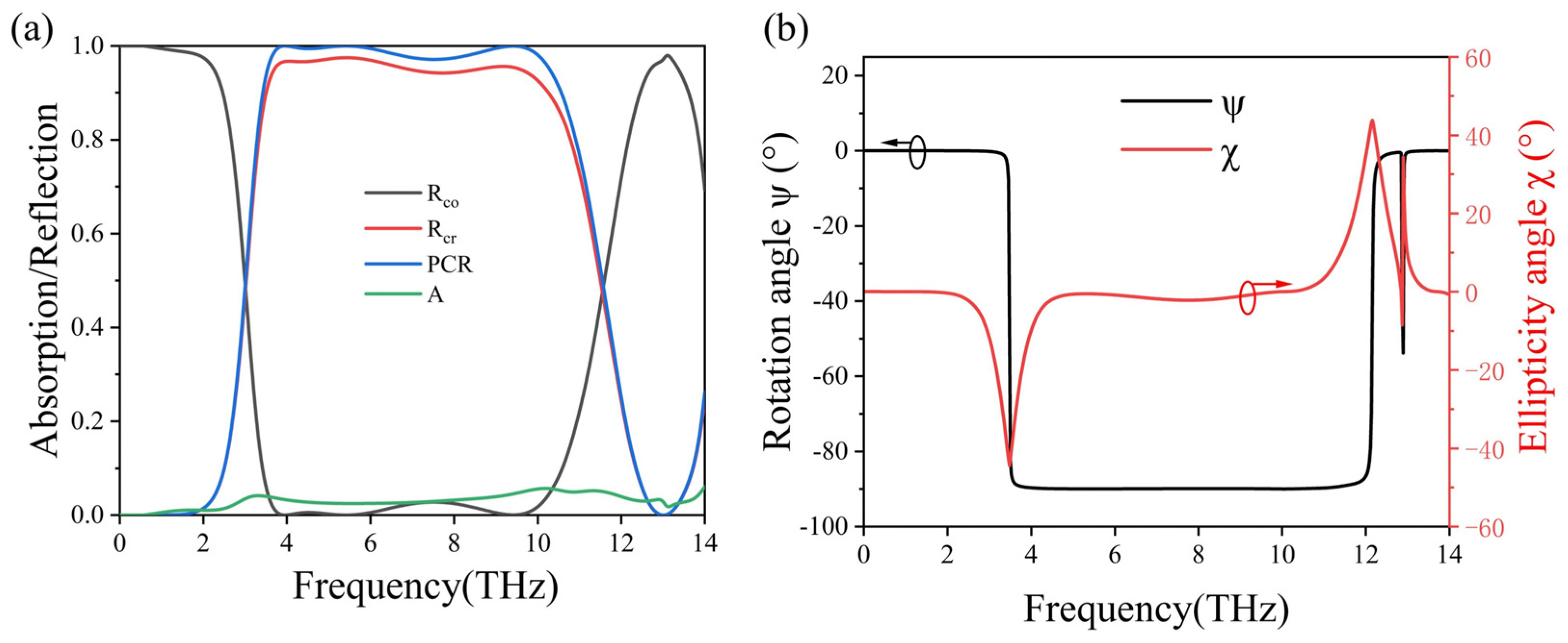
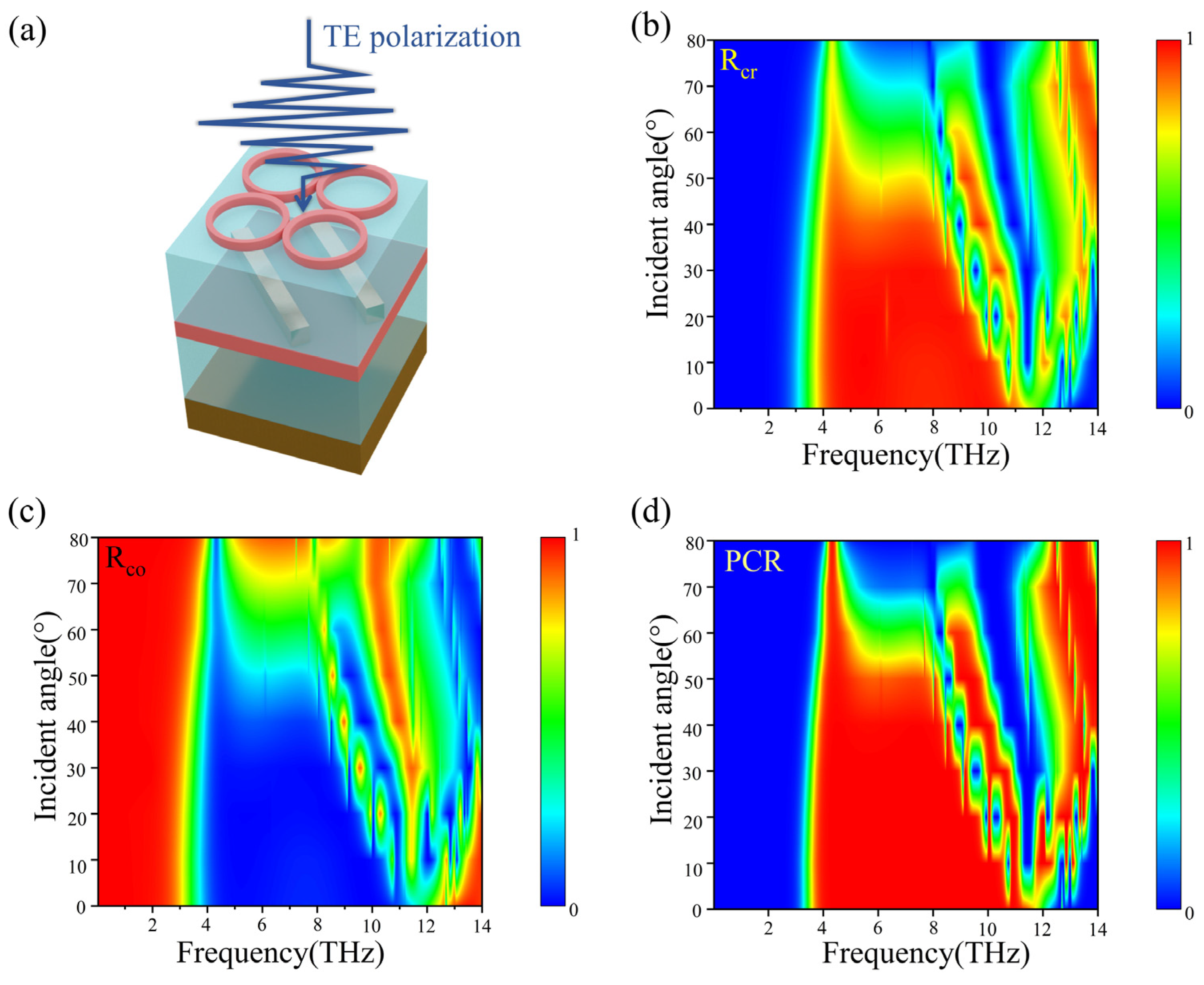
3.2. Effective Polarization Converter with the Proposed Metasurface Structure

By manipulating the external temperature of the metasurface, the phase transition of VO2 from the metallic state to the dielectric state is accomplished. Once a fully insulating state is attained, VO2 enables our structure to shift from functioning as an absorber to operating as a polarizer, without the requirement of any geometrical alterations. In this case, the conductivity of the VO2 material is σ = 10 S/m. To investigate the structure’s polarization conversion efficiency, we calculate the cross-polarized (Rcr) and co-polarized (Rco) reflection as a function of frequency. Since the electric field of the incident electromagnetic wave is polarized along the y-axis, the cross-polarization Rcr [48] is defined as R cr = | E x Reflec / E y Inc | , where E y Inc is the electric field of the y-polarized incident waves and E x Reflec is the x component of the reflected waves. Similarly, the co-polarization is expressed as R co = | E y Reflec / E y Inc | , where E y Reflec is the y component of the reflected waves. We define the polarization conversion ratio (PCR) as PCR = Rcr/(Rco + Rcr) to further reveal the efficiency of the proposed polarization converter. As Figure 6a clearly indicates, the cross-polarization Rcr consistently outperforms the co-polarization Rco over a wide frequency spectrum, ranging from 3.51 to 10.26 THz. Notably, the PCR remains above 97% across this extensive frequency range, as highlighted by the blue line in Figure 6a. As a result, the relative bandwidth is up to 98%. We also present the absorption spectrum of the structure in Figure 6a for comparison with the findings depicted in Figure 2a. This juxtaposition between Figure 6a and Figure 2a clearly demonstrates the structure’s transition from a broadband absorber to a wideband polarizer.
To accurately characterize the polarization state of the reflective polarization converter, the Stokes method is introduced [49,50], and four parameters are defined as:
S 0 = r x y 2 + r y y 2 S 1 = r x y 2 r y y 2 S 2 = 2 r x y r y y c o s ( Δ φ ) S 3 = 2 r x y r y y s i n ( Δ φ )
where rij (i, j = x, y) is the calculated i-polarized reflection coefficient from the j-polarized incidence. Δ φ is the phase difference of rxy and ryy. The benchmark for pure linear polarization conversion is determined by the polarization rotation angle ψ and the ellipticity angle χ, which can be computed by Stokes parameters in Equation (2):
t a n 2 ψ = S 2 / S 1 χ = a r c s i n ( S 3 / S 0 )
Figure 6b illustrates the polarization rotation angle and ellipticity angle when a y-polarized plane wave is excited under normal incidence. The polarization rotation angle ψ , represented by the black line, remains at −90° across a wide frequency range from 3.5 to 12 THz. This signifies that the reflected wave undergoes approximately a 90° rotation after passing through the proposed structure, transitioning from a y-polarized incident wave. Additionally, the ellipticity angle χ maintains near 0° between 4.8 to 10.26 THz, indicating that the reflected wave maintains a very high purity of linear polarization. These findings suggest that the designed structure effectively converts a y-polarized incident wave to a nearly pure x-polarized wave over a broad frequency range.
We conduct an investigation of the polarization conversion mechanism by examining the formation of a Fabry–Perot cavity with the Cu substrate and an array of Cu strips [44], since the current VO2 material is in a fully insulting state. The subsequent interference from polarization coupling during multiple reflections can be attributed to the enhancement or reduction of the total reflected field involving co-polarization and cross-polarization. For easier analysis, we orthogonally split the incident y-polarized wave into two components along the u-axis and the v-axis, as shown in Figure 7a. We calculate the respective reflections rij (where i, j = u, v), indicating the reflection of an i-polarized wave from a j-polarized incident wave. The findings, illustrated in Figure 7b, reveal that both ruu and rvv values remain above 0.9 across the entire computation range, except for a notable dip in reflection at around 13 THz. Conversely, the reflections ruv and rvu are so minimal that they are practically negligible. Consequently, our analysis focuses solely on the phases φ u u , φ v v , and their phase difference Δ φ , as displayed in Figure 7c,d. Figure 7d highlights that the phase difference spans from 4.2 to 11.78 THz, roughly equating to 180° or −180°. This suggests that the combined reflected waves are diverted by 90° relative to the incoming waves.
As we have analyzed, the linear polarization converter is largely attributed to the design of the Cu strips and the Cu reflective layer on the bottom. We delve into how the Cu strips—specifically, the length L and the width d—affect the reflection of cross-polarized light and the PCR. As illustrated in Figure 8a, we observe that as the Cu strip length L increases from 8 μm to 18 μm, the bandwidth for cross-polarization progressively broadens. Concurrently, the entire spectral profile exhibits a red shift, with the lower frequency end elevating until it aligns with the higher frequency end. This results in an expansion of the cross-polarization bandwidth, which attains its maximum when L equals 18 μm. Figure 8b illustrates the evolution of the PCR as the length L of the Cu strips increases from 8 μm to 18 μm. During this process, the PCR spectral profile evolves from a singular peak to a broadband configuration characterized by multiple peaks, mirroring the cross-polarization observed in Figure 8a. Throughout this transformation, the entire spectral line experiences a red shift, while the elevation in the lower frequency region gradually nears unity, ultimately resulting in the emergence of a broadband spectral line. Similarly, the impact of the Cu strip width d on the cross-polarization reflection amplitude is explored in Figure 8c. As the width d increases from 0.5 μm to 2 μm, the amplitude of the cross-polarization reflection steadily increases, stabilizes, and its bandwidth broadens, ultimately achieving maximum bandwidth. As shown in Figure 8d, the amplitude of the PCR remains essentially constant, while the bandwidth progressively widens. From this parameter analysis, it is concluded that both the length and width substantially impact the polarization converter’s bandwidth, with the variation in length L exerting a more pronounced effect on the conversion efficiency.
Finally, to gain a deeper insight into the characteristics of the linearly polarized converter, we simulate the reflection coefficient and PCR at different incidence angles under y-polarization, as depicted in Figure 9a. Figure 9b shows the color map of the cross-polarized reflection Rcr as a function of the incidence angle and frequency, demonstrating that the reflection bandwidth of the cross-polarized reflection (>90%) incrementally narrows as the incidence angle is increased from 0 to 50°. The magnitude of the cross-polarized reflection decreases when the angle of incidence exceeds 50°. In Figure 9c, we observe that the co-polarized reflection Rco climbs as the angle of incidence increases within the operational frequency range, yet remains under 0.1 for angles of incidence below 50°. In addition, we observe that the impact on the PCR value is minimal with an incident angle smaller than 50°, and the bandwidth begins to narrow progressively. From these observations, it can be deduced that the designed metasurface structure is capable of delivering robust linear polarization performance at incidence angles up to 50°. This suggests that the linear polarization converter can sustain its linear polarization functionality effectively even at larger angles of incidence.
As has been documented, there is extensive research on multifunctional devices utilizing active materials. This study highlights the broad bandwidth achieved for both absorption and polarization conversion using the same structure. To evaluate our metasurface structure’s bandwidth, we compared its absorption and polarization conversion bandwidth, along with their relative bandwidths, to those of other notable multifunctional devices reported recently. Table 1 shows that our devices outperform others in terms of broader absorption and polarization conversion capabilities, along with a larger relative bandwidth. Moreover, our device presents the benefits of being more compact and featuring a thinner thickness, indicating a wider scope of potential applications.

4. Conclusions

In summary, we have demonstrated a versatile THz metasurface that can switch from ultra-broadband absorption to linear polarization conversion by use of the metal-to-insulator transition of VO2. Results have shown that when VO2 is in the metallic state, the metasurface device acts as an ultra-broadband absorber, covering a spectrum from 4.95 to 18.39 THz, and is unaffected by polarization, working well even at large incident angles. By changing the phase of VO2 into the insulating state, the device becomes a polarization converter with broadband cross-polarization reflection across 3.51 to 10.26 THz. This enables a seamless switch between absorption and polarization conversion over a wide frequency range from 4.95 to 10.26 THz, by electrically, thermally, or optically adjusting the VO2 state, without altering the device’s geometry. The findings presented in this paper demonstrate the advantages of the proposed stacked structure, including switchable functions, ultra-broadband operation, and efficient conversion, suggesting its potential applications in optical switching, temperature-sensitive sensors, and other tunable THz devices in various fields.

Author Contributions

W.Z.: Methodology, Conceptualization, Formal analysis, Writing—original draft. C.Z.: Validation, Methodology. L.H.: Resources, Software, Visualization. J.L.: Resources, Software, Visualization. Y.S.: Methodology, Data curation. X.D.: Investigation, Project administration. J.C.: Writing—review and editing, Project administration, Funding acquisition. T.G.: Writing—review and editing, Project administration, Funding acquisition. All authors have read and agreed to the published version of the manuscript.

Funding

This work has been supported by the National Natural Science Foundation of China (Grant No. 12104203, 12274241, 12264027, 61927813), Jiangxi Double-Thousand Plan (Grant No. jxsq2023101069), and Jiangxi Provincial Natural Science Foundation (Grant No. 20224BAB211015).

Data Availability Statement

Data underlying the results presented in this paper are not publicly available at this time but may be obtained from the authors upon reasonable request.

Acknowledgments

All the authors have accepted responsibility for the entire content of this submitted manuscript and approved submission.

Conflicts of Interest

The authors declare that they have no known competing financial interests or personal relationships that could have appeared to influence the work reported in this paper.

References

  1. Hu, J.; Bandyopadhyay, S.; Liu, Y.-H.; Shao, L.-Y. A Review on Metasurface: From Principle to Smart Metadevices. Front. Phys. 2021, 8, 586087. [Google Scholar] [CrossRef]
  2. Li, W.; Zhao, W.; Cheng, S.; Zhang, H.; Yi, Z.; Sun, T.; Wu, P.; Zeng, Q.; Raza, R. Tunable metamaterial absorption device based on Fabry–Perot resonance as temperature and refractive index sensing. Opt. Lasers Eng. 2024, 181, 108368. [Google Scholar] [CrossRef]
  3. Liang, S.; Xu, F.; Li, W.; Yang, W.; Cheng, S.; Yang, H.; Chen, J.; Yi, Z.; Jiang, P. Tunable smart mid infrared thermal control emitter based on phase change material VO2 thin film. Appl. Therm. Eng. 2023, 232, 121074. [Google Scholar] [CrossRef]
  4. Liang, S.; Cheng, S.; Zhang, H.; Yang, W.; Yi, Z.; Zeng, Q.; Tang, B.; Wu, P.; Ahmad, S.; Sun, T. Structural color tunable intelligent mid-infrared thermal control emitter. Ceram. Int. 2024, 50, 23611–23620. [Google Scholar] [CrossRef]
  5. Li, W.; Liu, Y.; Ling, L.; Sheng, Z.; Cheng, S.; Yi, Z.; Wu, P.; Zeng, Q.; Tang, B.; Ahmad, S. The tunable absorber films of grating structure of AlCuFe quasicrystal with high Q and refractive index sensitivity. Surf. Interfaces 2024, 48, 104248. [Google Scholar] [CrossRef]
  6. Li, W.; Liu, M.; Cheng, S.; Zhang, H.; Yang, W.; Yi, Z.; Zeng, Q.; Tang, B.; Ahmad, S.; Sun, T. Polarization independent tunable bandwidth absorber based on single-layer graphene. Diam. Relat. Mater. 2024, 142, 110793. [Google Scholar] [CrossRef]
  7. Cheng, Y.; Fan, J.; Luo, H.; Chen, F. Dual-Band and High-Efficiency Circular Polarization Convertor Based on Anisotropic Metamaterial. IEEE Access 2020, 8, 7615–7621. [Google Scholar] [CrossRef]
  8. Chen, H.-T.; Taylor, A.J.; Yu, N. A review of metasurfaces: Physics and applications. Rep. Prog. Phys. 2016, 79, 076401. [Google Scholar] [CrossRef] [PubMed]
  9. Guo, T.; Argyropoulos, C. Broadband polarizers based on graphene metasurfaces. Opt. Lett. 2016, 41, 5592–5595. [Google Scholar] [CrossRef]
  10. Wang, C.; Liu, W.; Li, Z.; Cheng, H.; Li, Z.; Chen, S.; Tian, J. Dynamically Tunable Deep Subwavelength High-Order Anomalous Reflection Using Graphene Metasurfaces. Adv. Opt. Mater. 2018, 6, 1701047. [Google Scholar] [CrossRef]
  11. Boyce, A.M.; Stewart, J.W.; Avila, J.; Shen, Q.; Zhang, S.; Wheeler, V.D.; Mikkelsen, M.H. Actively Tunable Metasurfaces via Plasmonic Nanogap Cavities withSub-10-nm VO2 Films. Nano Lett. 2022, 22, 3525–3531. [Google Scholar] [CrossRef] [PubMed]
  12. Peng, C.; Ou, K.; Li, G.; Li, X.; Wang, W.; Zhao, Z.; Li, X.; Chen, X.; Lu, W. Tunable phase change polaritonic perfect absorber in the mid-infrared region. Opt. Express 2020, 28, 11721–11729. [Google Scholar] [CrossRef] [PubMed]
  13. Liang, J.; Zhang, K.; Lei, D.; Yu, L.; Wang, S. Bandwidth-tunable THz absorber based on diagonally distributed double-sized VO2 disks. Appl. Opt. 2021, 60, 3062–3070. [Google Scholar] [CrossRef] [PubMed]
  14. Zhang, Y.; Chen, D.; Ma, W.; You, S.; Zhang, J.; Fan, M.; Zhou, C. Active optical modulation of quasi-BICs in Si-VO2 hybrid metasurfaces. Opt. Lett. 2022, 47, 5517–5520. [Google Scholar] [CrossRef] [PubMed]
  15. Hao, J.-M.; Qiu, M.; Zhou, L. Manipulate light polarizations with metamaterials: From microwave to visible. Front. Phys. China 2010, 5, 291–307. [Google Scholar] [CrossRef]
  16. Ding, F.; Deshpande, R.; Meng, C.; Bozhevolnyi, S.I. Metasurface-enabled broadband beam splitters integrated with quarter-wave plate functionality. Nanoscale 2020, 12, 14106–14111. [Google Scholar] [CrossRef] [PubMed]
  17. Iwanaga, M. All-Dielectric Metasurface Fluorescence Biosensors for High-Sensitivity Antibody/Antigen Detection. ACS Nano 2020, 14, 17458–17467. [Google Scholar] [CrossRef] [PubMed]
  18. Lee, C.; Jeon, S.; Kim, S.J. Near-flat top bandpass filter based on non-local resonance in a dielectric metasurface. Opt Express 2023, 31, 4920–4931. [Google Scholar] [CrossRef]
  19. Liu, W.; Zhang, L.; Ke, J.; Liang, J.; Xiao, C.; Cheng, Q.; Cui, T.J. Metasurface-based broadband polarization-insensitive polarization rotator. Opt Express 2022, 30, 34645–34654. [Google Scholar] [CrossRef]
  20. Zheng, Z.; Luo, Y.; Yang, H.; Yi, Z.; Zhang, J.; Song, Q.; Yang, W.; Liu, C.; Wu, X.; Wu, P. Thermal tuning of terahertz metamaterial absorber properties based on VO2. Phys. Chem. Chem. Phys. 2022, 24, 8846–8853. [Google Scholar] [CrossRef] [PubMed]
  21. Guo, T.; Argyropoulos, C. Tunable and broadband coherent perfect absorbers with nonlinear and amplification performance based on asymmetric bifacial graphene metasurfaces. J. Opt. 2020, 22, 084003. [Google Scholar] [CrossRef]
  22. Barkabian, M.; Sharifi, N.; Granpayeh, N. Multi-functional high-efficiency reflective polarization converter based on an ultra-thin graphene metasurface in the THz band. Opt. Express 2021, 29, 20160–20174. [Google Scholar] [CrossRef]
  23. Wu, Z.; Tian, J.; Yang, R. A graphene based dual-band metamaterial absorber for TE polarized THz wave. Micro Nanostruct. 2022, 168, 207331. [Google Scholar] [CrossRef]
  24. Yang, G.; Yan, F.; Du, X.; Li, T.; Wang, W.; Lv, Y.; Zhou, H.; Hou, Y. Tunable broadband terahertz metamaterial absorber based on vanadium dioxide. AIP Advances 2022, 12, 045219. [Google Scholar] [CrossRef]
  25. Song, Z.; Chen, A.; Zhang, J. Terahertz switching between broadband absorption and narrowband absorption. Opt. Express 2020, 28, 2037–2044. [Google Scholar] [CrossRef]
  26. Li, Y.; Luo, J.; Li, X.; Li, T.; Wang, W.; Lv, Y.; Zhou, H.; Hou, Y. Switchable Quarter-Wave Plate and Half-Wave Plate Based on Phase-Change Metasurface. IEEE Photonics J. 2020, 12, 045219. [Google Scholar] [CrossRef]
  27. Zhao, J.-X.; Song, J.-L.; Zhou, Y.; Liu, Y.-C.; Zhou, J.-H. Switching between the Functions of Half-Wave Plate and Quarter-Wave Plate Simply by Using a Vanadium Dioxide Film in a Terahertz Metamaterial. Chin. Phys. Lett. 2020, 37, 064204. [Google Scholar] [CrossRef]
  28. Lang, T.; Shen, T.; Wang, G.; Shen, C. Tunable broadband all-silicon terahertz absorber based on a simple metamaterial structure. Appl. Opt. 2020, 59, 6265–6270. [Google Scholar] [CrossRef] [PubMed]
  29. Chen, J.; Chen, X.; Liu, K.; Zhang, S.; Cao, T.; Tian, Z. A Thermally Switchable Bifunctional Metasurface for Broadband Polarization Conversion and Absorption Based on Phase-Change Material. Adv. Photonics Res. 2022, 3, 2100369. [Google Scholar] [CrossRef]
  30. Zou, H.; Cheng, Y. Design of a six-band terahertz metamaterial absorber for temperature sensing application. Opt. Mater. 2019, 88, 674–679. [Google Scholar] [CrossRef]
  31. Argyropoulos, C. Enhanced transmission modulation based on dielectric metasurfaces loaded with graphene. Opt. Express 2015, 23, 23787–23797. [Google Scholar] [CrossRef] [PubMed]
  32. Guo, T.; Argyropoulos, C. Hybrid graphene-plasmon gratings. J. Appl. Phys. 2023, 134, 050901. [Google Scholar] [CrossRef]
  33. Guo, L.; Zhang, K.; Zhang, X.; Chen, B.; Kong, W. Function switchable broadband wave plate based on the Au-VO2 hybrid metasurface. Opt. Lett. 2022, 47, 4818–4821. [Google Scholar] [CrossRef]
  34. Yang, Z.; Ko, C.; Ramanathan, S. Oxide Electronics Utilizing Ultrafast Metal-Insulator Transitions. Annu. Rev. Mater. Res. 2011, 41, 337–367. [Google Scholar] [CrossRef]
  35. Cueff, S.; John, J.; Zhang, Z.; Parra, J.; Sun, J.; Orobtchouk, R.; Ramanathan, S.; Sanchis, P. VO2 nanophotonics. Apl Photonics 2020, 5, 110901. [Google Scholar] [CrossRef]
  36. Shi, R.; Cai, X.; Wang, W.; Wang, J.; Kong, D.; Cai, N.; Chen, P.; He, P.; Wu, Z.; Amini, A. Single-Crystalline Vanadium Dioxide Actuators. Adv. Funct. Mater. 2019, 29, 1900527. [Google Scholar] [CrossRef]
  37. Chen, B.; Yang, S.; Chen, J.; Wu, J.; Chen, K.; Li, W.; Tan, Y.; Wang, Z.; Qiu, H.; Fan, K. Directional terahertz holography with thermally active Janus metasurface. Light-Sci. Appl. 2023, 12, 136. [Google Scholar] [CrossRef] [PubMed]
  38. He, J.; Shi, Z.; Ye, S.; Li, M.; Dong, J. Reconfigurable all-dielectric metasurface based on GSST. Results Phys. 2022, 42, 106017. [Google Scholar] [CrossRef]
  39. Luo, J.; Shi, X.; Luo, X.; Hu, F.; Li, G. Broadband switchable terahertz half-/quarter-wave plate based on metal-VO2 metamaterials. Opt. Express 2020, 28, 30861–30870. [Google Scholar] [CrossRef]
  40. Song, Z.; Zhang, J. Achieving broadband absorption and polarization conversion with a vanadium dioxide metasurface in the same terahertz frequencies. Opt. Express 2020, 28, 12487–12497. [Google Scholar] [CrossRef]
  41. Wei, H.; Ge, H.; Zhao, T.; Sharma, S.; Petru, M.; Dwivedi, S.P.; Kumar, A.; Abbas, M. Vanadium dioxide thin films-assisted terahertz meta-surface for simultaneous absorption, polarization conversion bi-functional switching, and wavefront operation. Results Phys. 2023, 53, 106970. [Google Scholar] [CrossRef]
  42. Liu, N.; Langguth, L.; Weiss, T.; Kästel, J.; Fleischhauer, M.; Pfau, T.; Giessen, H. Plasmonic analogue of electromagnetically induced transparency at the Drude damping limit. Nat. Mater. 2009, 8, 758–762. [Google Scholar] [CrossRef] [PubMed]
  43. Song, Z.; Deng, Y.; Zhou, Y.; Liu, Z. Terahertz toroidal metamaterial with tunable properties. Opt. Express 2019, 27, 5792–5797. [Google Scholar] [CrossRef]
  44. Wang, S.; Kang, L.; Werner, D.H. Hybrid Resonators and Highly Tunable Terahertz Metamaterials Enabled by Vanadium Dioxide (VO2). Sci. Rep. 2017, 7, 4326. [Google Scholar] [CrossRef]
  45. Liu, M.; Hwang, H.Y.; Tao, H.; Strikwerda, A.C.; Fan, K.; Keiser, G.R.; Sternbach, A.J.; West, K.G.; Kittiwatanakul, S.; Lu, J. Terahertz-field-induced insulator-to-metal transition in vanadium dioxide metamaterial. Nature 2012, 487, 345–348. [Google Scholar] [CrossRef] [PubMed]
  46. Chen, X.D.; Grzegorczyk, T.M.; Wu, B.I.; Pacheco, J., Jr.; Kong, J.A. Robust method to retrieve the constitutive effective parameters of metamaterials. Phys. Rev. E 2004, 70, 016608. [Google Scholar] [CrossRef]
  47. Smith, D.R.; Schultz, S.; Markoš, P.; Soukoulis, C.M. Determination of effective permittivity and permeability of metamaterials from reflection and transmission coefficients. Phys. Rev. B 2002, 65, 195104. [Google Scholar] [CrossRef]
  48. Jiang, Y.; Wang, L.; Wang, J.; Akwuruoha, C.N.; Cao, W. Ultra-wideband high-efficiency reflective linear-to-circular polarization converter based on metasurface at terahertz frequencies. Opt. Express 2017, 25, 27616–27623. [Google Scholar] [CrossRef] [PubMed]
  49. Grady, N.K.; Heyes, J.E.; Chowdhury, D.R.; Zeng, Y.; Reiten, M.T.; Azad, A.K.; Taylor, A.J.; Dalvit, D.A.R.; Chen, H.-T. Terahertz Metamaterials for Linear Polarization Conversion and Anomalous Refraction. Science 2013, 340, 1304–1307. [Google Scholar] [CrossRef]
  50. Jing, X.; Gui, X.; Zhou, P.; Hong, Z. Physical Explanation of Fabry-Perot Cavity for Broadband Bilayer Metamaterials Polarization Converter. J. Light. Technol. 2018, 36, 2322–2327. [Google Scholar] [CrossRef]
  51. Peng, Z.; Zheng, Z.; Yu, Z.; Lan, H.; Zhang, M.; Wang, S.; Li, L.; Liang, H.; Su, H. Broadband absorption and polarization conversion switchable terahertz metamaterial device based on vanadium dioxide. Opt. Laser Technol. 2023, 157, 108723. [Google Scholar] [CrossRef]
  52. Ma, M.; Lian, X.; Tian, J.; Yang, R. Dual function tunable THz metamaterial device possessing broadband absorption and polarization conversion. AEU Int. J. Electron. Commun. 2023, 163, 154602. [Google Scholar] [CrossRef]
  53. Liu, W.; Song, Z. Terahertz absorption modulator with largely tunable bandwidth and intensity. Carbon 2021, 174, 617–624. [Google Scholar] [CrossRef]
  54. Lian, X.; Ma, M.; Tian, J.; Yang, R.; Wu, X. Vanadium dioxide based bifunctional metasurface for broadband absorption and cross-polarization conversion in THz range. Aeu-Int. J. Electron. Commun. 2023, 170, 154784. [Google Scholar] [CrossRef]
  55. Ding, F.; Zhong, S.; Bozhevolnyi, S.I. Vanadium Dioxide Integrated Metasurfaces with Switchable Functionalities at Terahertz Frequencies. Adv. Opt. Mater. 2018, 6, 1701204. [Google Scholar] [CrossRef]
  56. Zhang, H.; He, X.; Zhang, D.; Zhang, H. Multitasking device with switchable and tailored functions of ultra-broadband absorption and polarization conversion. Opt. Express 2022, 30, 23341–23358. [Google Scholar] [CrossRef]
Figure 1. (a) Schematic structure of the proposed VO2 metasurface structure with switchable functions of ultra-broadband absorption and polarization conversion in THz range. (b) The 3D schematic of one unit cell of the stacked structure, consisting of six layers from top to bottom: VO2 quadruple ring, dielectric layer, Cu stripes, VO2 film, dielectric layer, and Cu reflection layer. The optimized geometry parameters are P = 20 μm, h1 = 7.4 μm, h2 = 5 μm, t1 = 0.2 μm, and t2 = 0.1 μm. (c) The top view of a unit cell. The parameters of the VO2 quadruple ring are optimized with outer and inner radii R = 4 μm, and r = 3 μm, respectively. The distance from the ring center to the unit cell border is D = 6 μm. (d) The parameters of the middle Cu stripes. Their parameters are optimized as L = 18 μm and d = 2 μm. The spacing between the two strips is w1 = 5.35 μm.
Micromachines 15 00967 g001
Figure 2. (a) Simulated absorption, cross- and co-polarized reflection spectra of the proposed VO2 metasurface structure under y-polarization incidence, when VO2 is fully in a metallic state. (b) Real (black line) and imaginary (red dashed line) parts of the calculated relative effective impedance of the proposed VO2 metasurface structure.
Micromachines 15 00967 g002
Figure 3. The computed electric field distributions of the ultra-broadband absorber with y-polarized incidence at (a) 6 THz, (b) 8 THz, and (c) 12 THz with the VO2 in the metallic state.
Micromachines 15 00967 g003
Figure 4. The computed absorption contour plots of the proposed VO2 metasurface structure as a function of the frequency and (a) polarization angles; (b) incident angles of the excitation wave under y-polarization.
Micromachines 15 00967 g004
Figure 5. The simulated absorption of the proposed VO2 metasurface structure by varying (a) inner radius r, (b) thickness t3 of the VO2 ring. The VO2 material is in completely metallic state with a conductivity value of σ = 2 × 10⁵ S/m.
Micromachines 15 00967 g005
Figure 6. (a) The simulated co-polarized (Rco), cross-polarized (Rcr) reflection, PCR and the absorption (A) of the proposed VO2 metasurface structure under y-polarized plane wave excitation, when VO2 is in fully insulating state with a conductivity value of s = 10 S/m. (b) The computed polarization rotation angle y and ellipticity c of the proposed structure under normal incidence.
Micromachines 15 00967 g006
Figure 7. (a) Schematic diagram of the orthogonal decomposition of the metasurface polarizer into two components along the u- and v-axes. (b) The simulated reflection coefficients of the decomposed reflected wave, rvv, ruv, rvu, and ruu. (c) The computed phase of the reflection coefficients ruu and rvv. (d) Phase difference between the reflection coefficients ruu and rvv.
Micromachines 15 00967 g007
Figure 8. (a,b) The simulated (a) cross-polarized reflection, (b) PCR of the proposed structure by varying the length L of the Cu strips. (c,d) The simulated (c) cross-polarized reflection, (d) PCR of the proposed structure by varying the width d of the Cu strips. VO2 is in fully insulating state with a conductivity value of σ = 10 S/m.
Micromachines 15 00967 g008
Figure 9. (a) Schematic diagram of one unit cell under y-polarization incidence. The computed contour plots of the (b) cross-polarized reflection, (c) co-polarized reflection, and (d) PCR as a function of the frequency and incident angles of the excitation wave in y-polarization when VO2 is in a fully insulating state with a conductivity value of σ= 10 S/m.
Micromachines 15 00967 g009
Table 1. Comparison with recently reported multifunctional metasurfaces.
Ref.Principal
Material
Absorption
Bandwidth [THz]
Relative BandwidthPolarization Conversion Bandwidth PCR > 90% [THz]Relative
Bandwidth
Thickness [μm]
[51]VO2(1.03–2.62) 1.5987.1%(1.81–2.39) 0.5827.6%42.5
[52]VO2(1.80–4.05) 2.2576.9%(1.68–3.79) 2.1177.1%25.9
[53]VO2(1.97–4.63) 2.6680.6%(1.54–4.18) 2.6492.3%23.45
[54]VO2,
Graphene
0.74; 1.45-(0.335–1.275) 0.94116.77%85.5
[55]VO2(0.562–1.232) 0.6774.7%(0.63–1.12) 0.4956%76.3
[56]VO2,
PS *
(0.68–1.6) 0.9280.70%(0.82–1.6) 0.7864.46%48.6
This workVO2(4.95–18.39) 13.44115.1%(3.51–10.26) 6.7598%12.95
* PS represents photoconductive semiconductor.
Disclaimer/Publisher’s Note: The statements, opinions and data contained in all publications are solely those of the individual author(s) and contributor(s) and not of MDPI and/or the editor(s). MDPI and/or the editor(s) disclaim responsibility for any injury to people or property resulting from any ideas, methods, instructions or products referred to in the content.

