
Recent Research on Structural Design, Performance Optimization, and Applications of Piezoelectric Pumps

Abstract
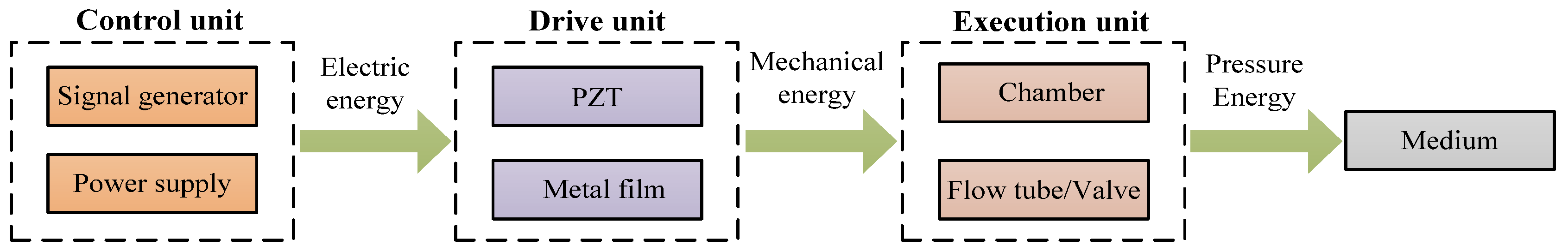
:1. Introduction
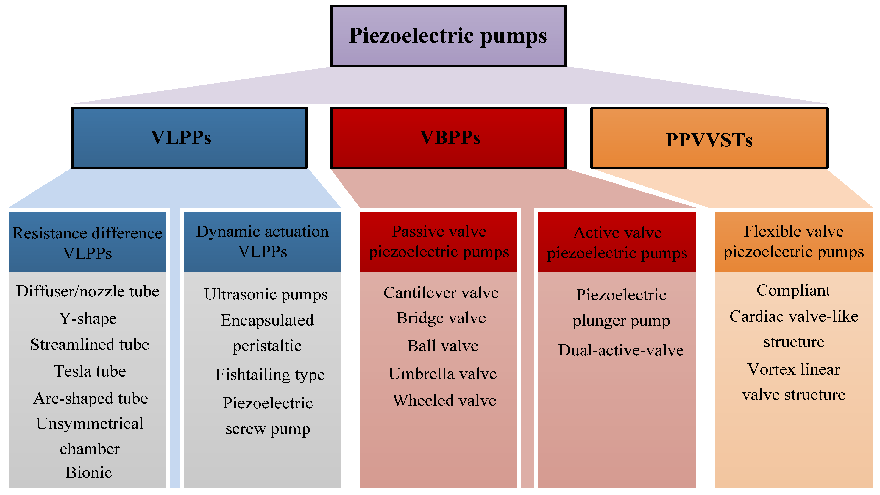
2. Classification of PPs
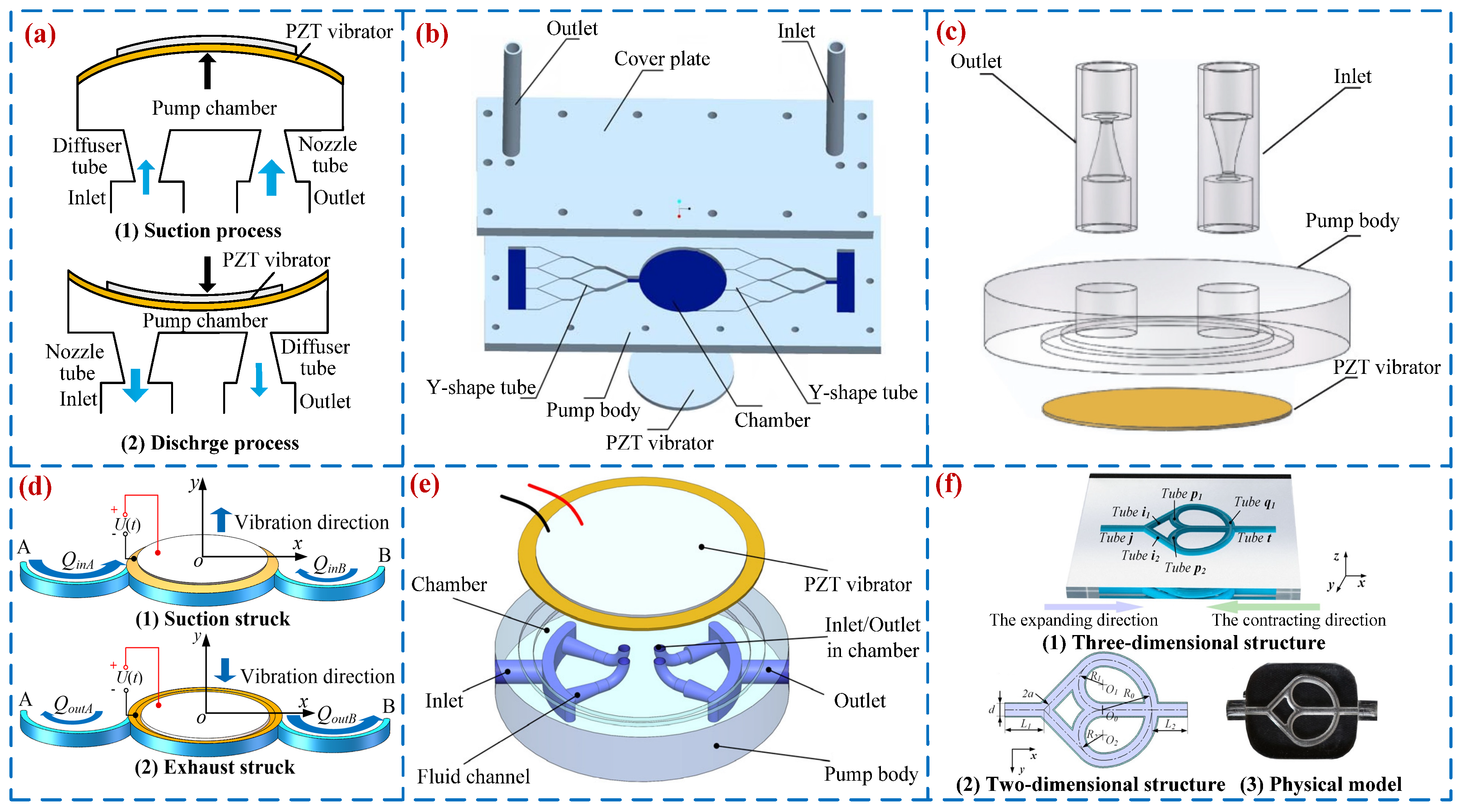
2.1. VLPPs
2.1.1. Resistance Difference VLPPs
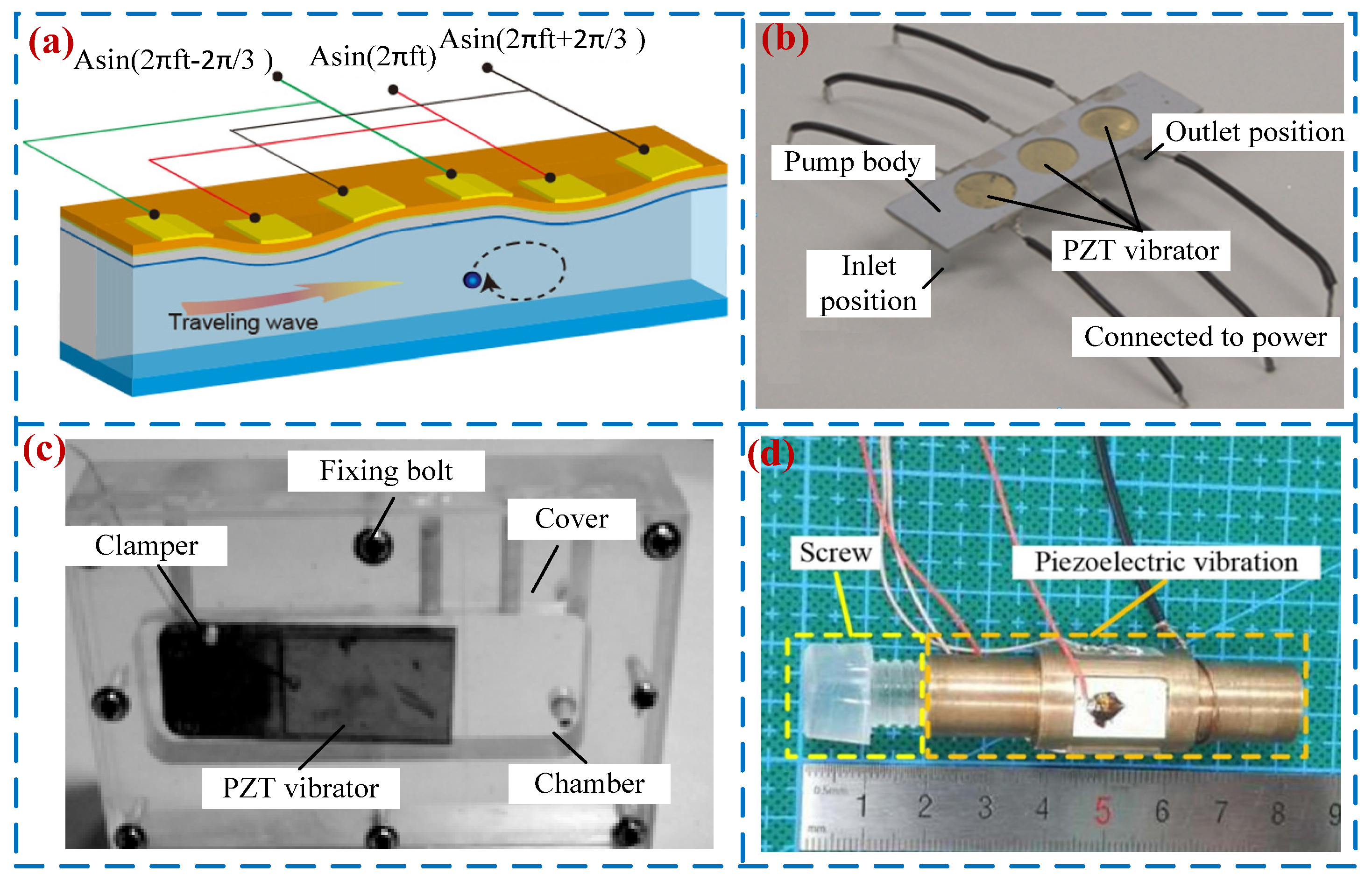
2.1.2. Dynamic Actuation VLPPs
2.2. VBPPs
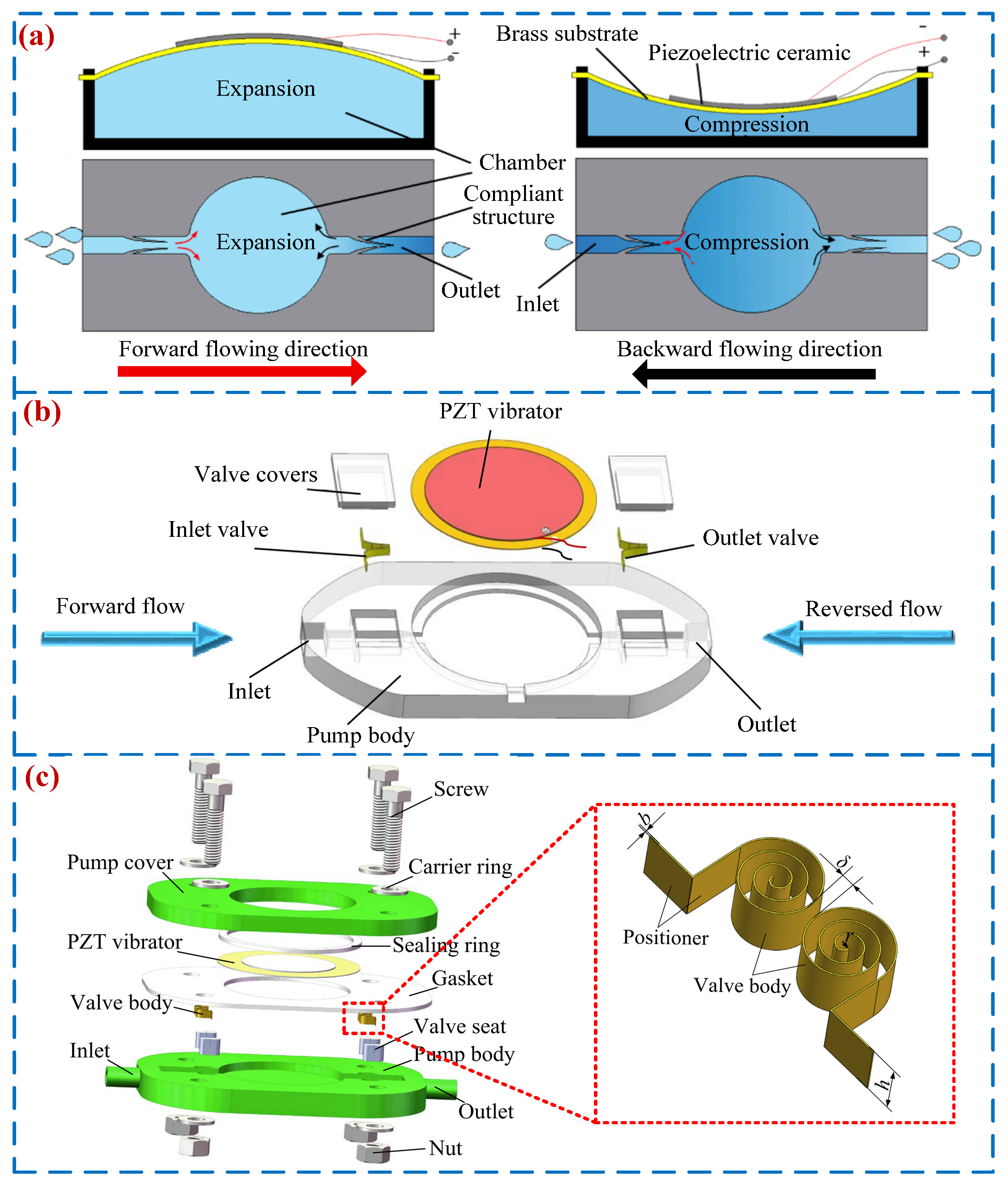
2.2.1. Passive Valve PPs
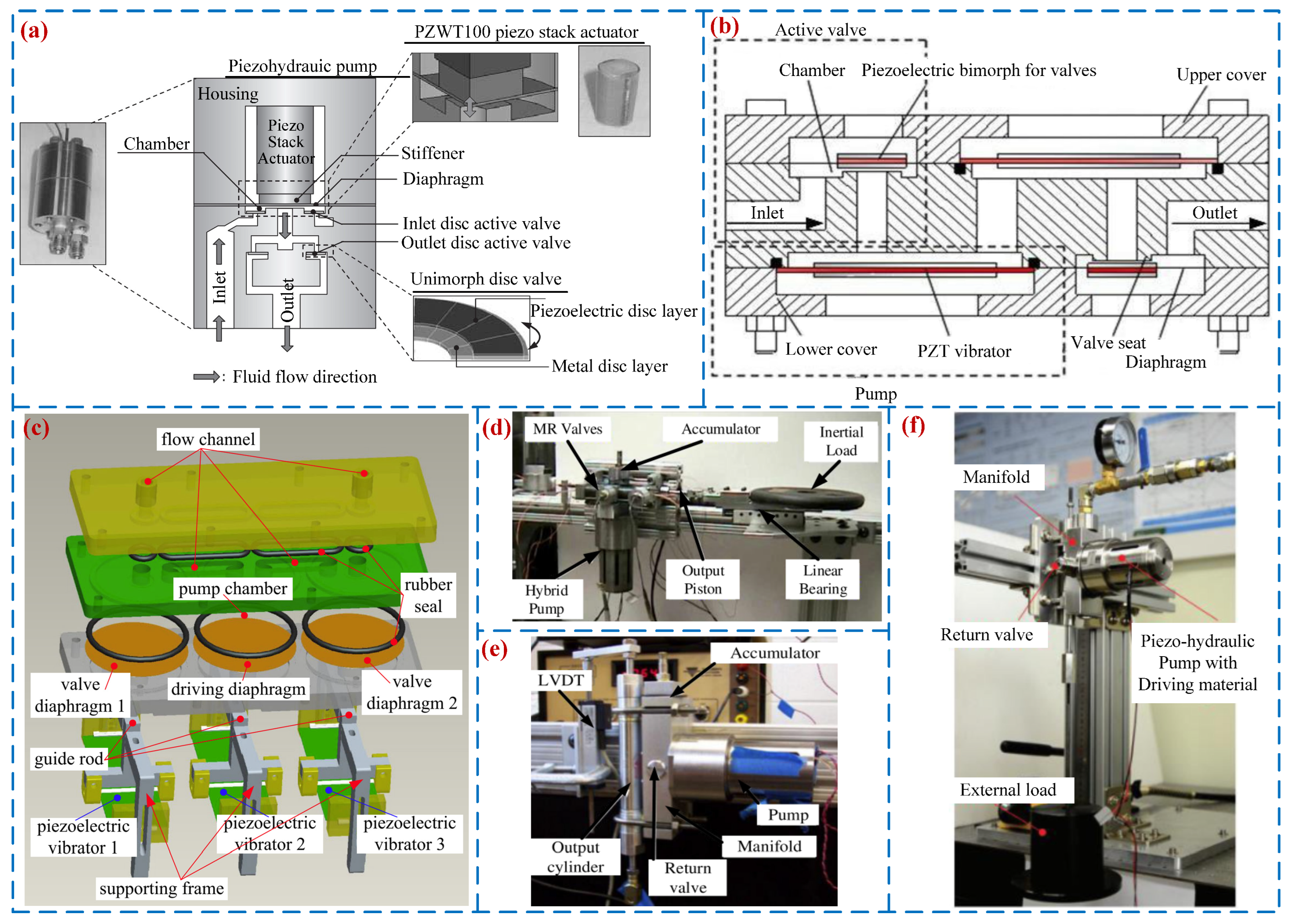
2.2.2. Active Valve PPs
2.3. PPVVSTs
2.4. Brief Analyses of VLPPs, VBPPs, and PPVVSTs
3. Chamber Configuration of PPs
3.1. SCPs
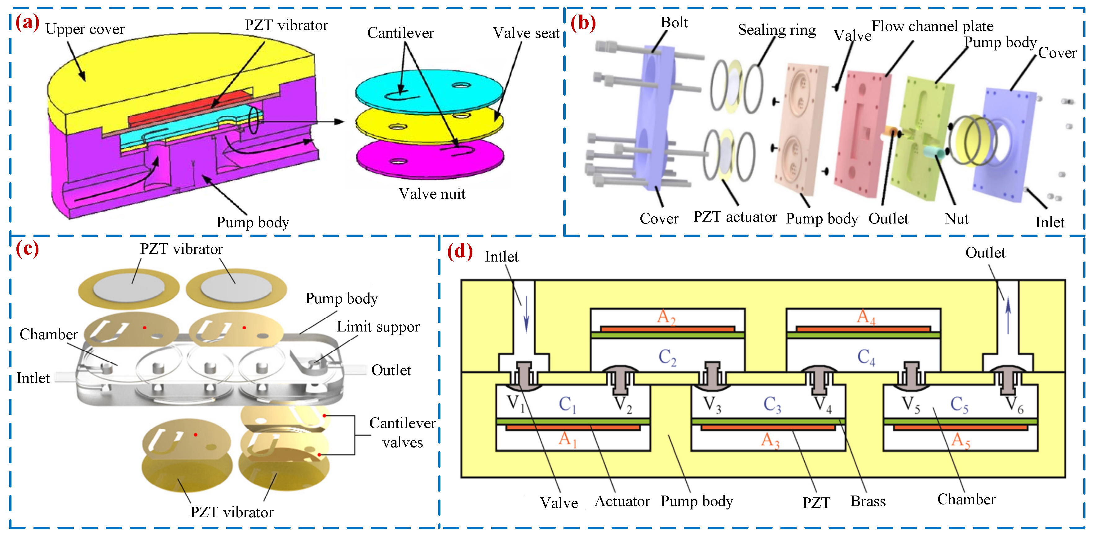
3.2. MCPs
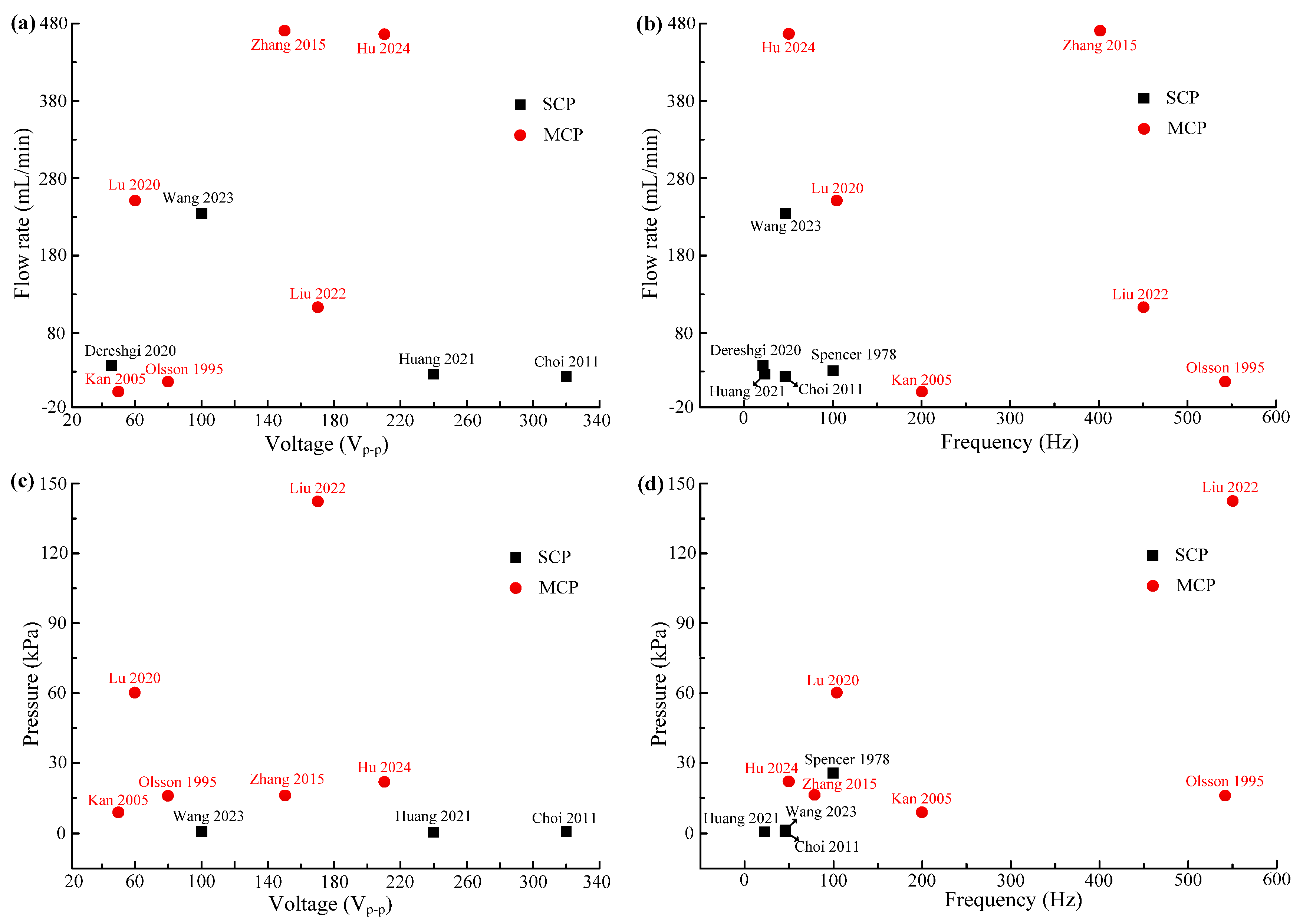
3.3. Brief Analyses of SCPs and MCPs
4. Optimization of PPs
4.1. Cavitation Inhibition Methods
4.2. Back-Flow Suppression Methods
4.3. Optimization of PZT Vibrator
4.4. Device Efficiency
5. Application of PPs
5.1. Chip Cooling
5.2. Biomedical Applications
5.3. Chemical Applications
5.4. Fuel Supply Applications
5.5. Other Applications
6. Analysis of the Current Research Status of PPs
7. Summary and Outlook
7.1. Summary
- (1)
- Based on the “valve” structure, PPs are classifiable as VLPPs, VBPPs, and PPVVSTs. VLPPs have the problem of “back-flow”, resulting in lower work efficiency. The output performance of VBPPs is superior to that of VLPPs, but VBPPs have the problem of “lagging of valve”. PPVVSTs can effectively solve the problems of “back-flow” in VLPPs and the problem of “lagging of valve” in VBPPs, thus further expanding the application of PPs.
- (2)
- Based on the number and arrangement of pump chambers, PPs can be divided into SCPs, multi-chamber series-type PPs, multi-chamber parallel-type PPs, and multi-chamber hybrid-type PPs. Compared with SCPs, MCPs have a significantly improved output performance. PPs can obtain the maximum flow rate when the pump chambers are connected in a series, and the maximum output pressure can be obtained when the pump chambers are connected in a mix.
- (3)
- In order to improve the output performance of PPs, optimization methods proposed by scholars have been summarized for the problems of cavitation and back-flow in PPs. Meanwhile, the structure and installation method of the PZT vibrators have been optimized to improve driving efficiency.
- (4)
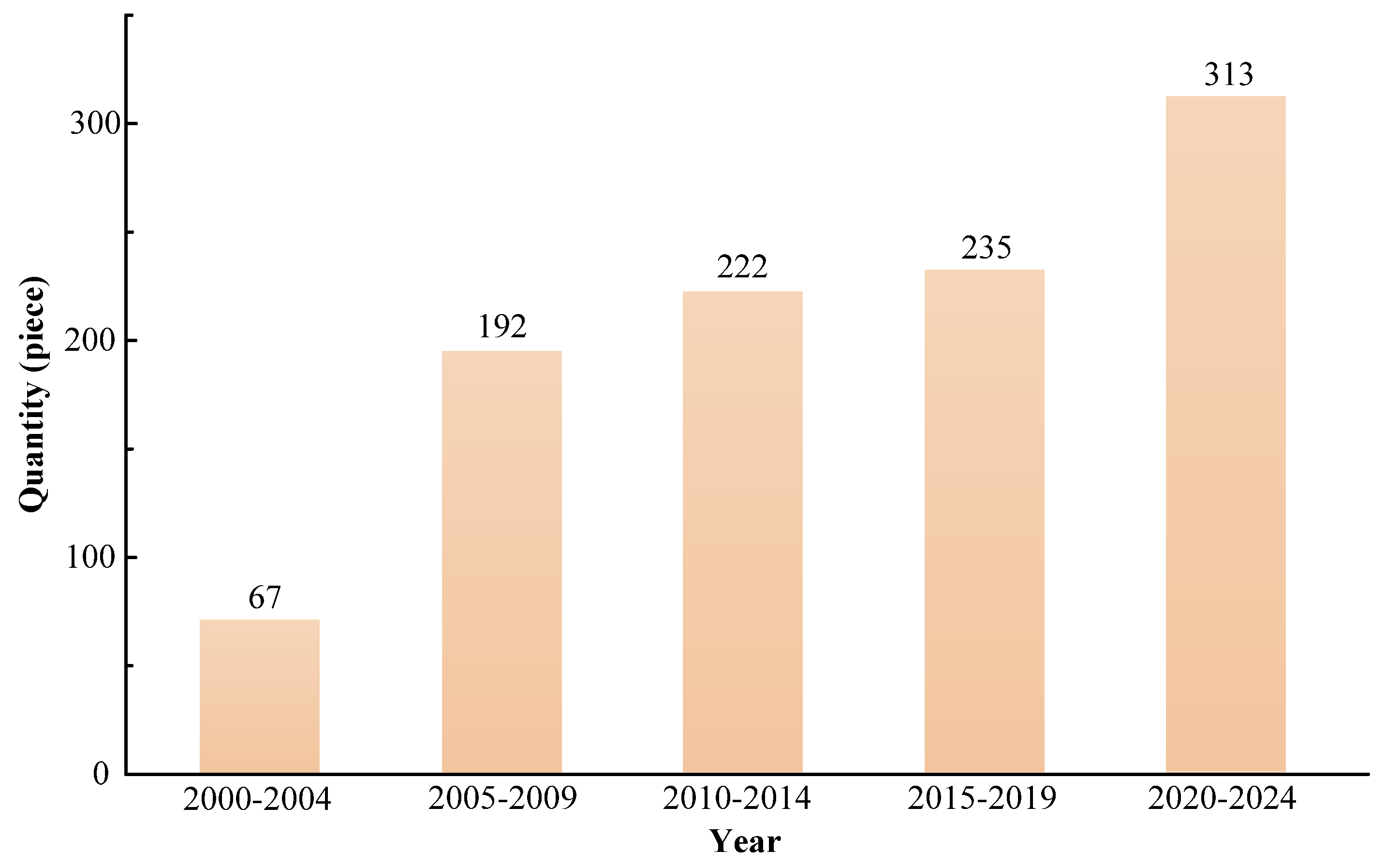
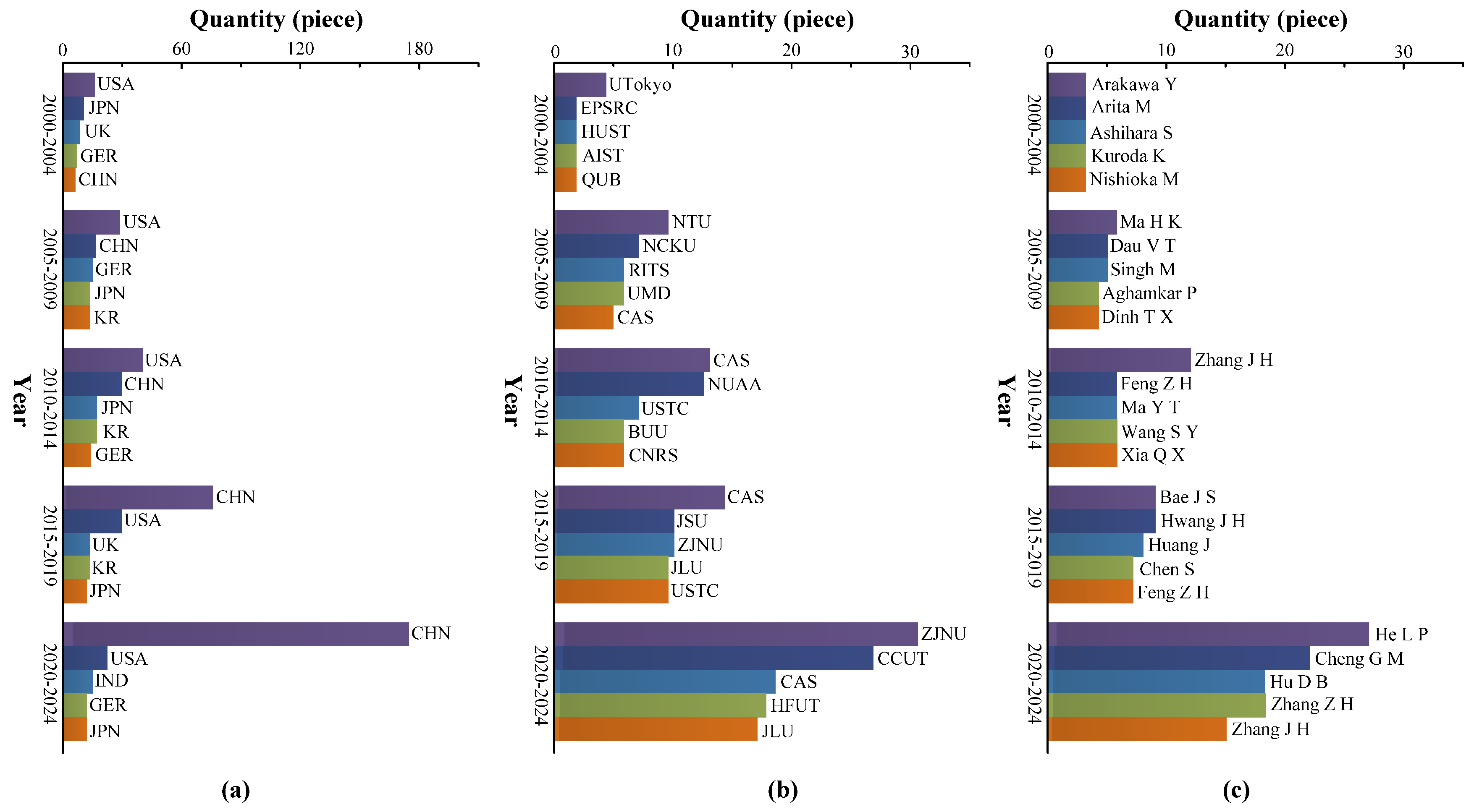
- At present, the demand for PPs in the microfluidic field is increasing, especially in areas such as chip cooling, biomedical, chemical analysis, and fuel supply. More and more countries, institutions, and scholars are conducting research in PPs, and CHN is the country with the fastest increase in research results in PPs.
7.2. Outlook
- (1)
- Integrated pump body structure
- (2)
- Pumping of high-viscosity medium
- (3)
- Miniaturization of pump body size
- (4)
- Diversified application fields
Funding
Conflicts of Interest
References
- Cao, D.; Ji, S.J.; Yang, Z.G. Design and analysis of a wheel valve piezoelectric micropump with high performance. Sens. Actuators A Phys. 2024, 377, 115624. [Google Scholar] [CrossRef]
- Sun, Y.M.; Deng, L.Y.; Wang, L.; Wang, J.Y. A phase modulation method of sine signal for dual-active-valve piezoelectric pump. Meas. Sci. Technol. 2024, 35, 086204. [Google Scholar] [CrossRef]
- Chen, S.; Fang, X.; Xie, Y.L.; Huang, Z.J.; Zhan, W.J.; Kan, J.W.; Zhang, Z.H.; Li, J.P. A piezoelectric pump with composite chamber: Using bluff body to improve its anti-clogging ability. Smart Mater. Struct. 2024, 33, 085011. [Google Scholar] [CrossRef]
- Chen, J.; Jin, R.; Gao, W.Z.; Liu, C.H.; Zeng, Y.S.; Wang, J.W. Development of an inertia-driven resonant piezoelectric stack pump based on the flexible support structure. Smart Mater. Struct. 2024, 33, 075017. [Google Scholar] [CrossRef]
- Wang, M.; Dong, L.T.; Liu, R.Y.; Wang, C.H.; Sun, X.D.; Li, X.B.; Liu, G.J.; Yang, Z.G. A high-performance piezoelectric micropump designed for precision delivery. Mech. Syst. Signal Process. 2024, 215, 111457. [Google Scholar] [CrossRef]
- Narasaki, T. Layered type bimorph vibrator pump. In Proceedings of the 13th Intersociety Energy Conversion Engineering Conference, San Diego, CA, USA, 20–25 August 1978; pp. 20–25. [Google Scholar]
- Yan, Q.F.; Yin, Y.K.; Sun, W.T.; Fu, J. Advances in valveless piezoelectric pumps. Appl. Sci. 2021, 11, 7061. [Google Scholar] [CrossRef]
- Huang, J.; Li, L.J.; Cong, X.G.; Zhu, G.P.; Affane, H.; Zhang, Q.; Wang, Y. Comparative experimental study of heat sinks with piezoelectric pump. Appl. Therm. Eng. 2023, 219, 119612. [Google Scholar] [CrossRef]
- He, L.P.; Wu, X.Q.; Zhang, Z.; Wang, J.R.; Hu, D.B.; Liu, Y.M.; Cheng, G.M. Thermal management analysis of serial-connection three-chamber piezoelectric pump. J. Mech. Sci. Technol. 2021, 35, 4523–4530. [Google Scholar] [CrossRef]
- Hu, R.H.; He, L.P.; Hu, D.B.; Hou, Y.; Cheng, G.M. Recent studies on the application of piezoelectric pump in different fields. Microsyst. Technol. 2023, 29, 663–682. [Google Scholar] [CrossRef]
- García, J.; Ríos, I.; Rico, F.F. Design and analyses of a transdermal drug delivery device (TD(3)) dagger. Sensors 2019, 19, 5090. [Google Scholar] [CrossRef]
- Haldkar, R.K.; Khalatkar, A.; Gupta, V.K.; Sheorey, T. New piezoelectric actuator design for enhance the micropump flow. Mater. Today Proc. 2021, 44, 776–781. [Google Scholar] [CrossRef]
- Karumuri, S.R.; Mohammed, H.; Guha, K.; Puli, A.K.; Einsanwi, A.; Kondavitee, G.S. Design, simulation and analysis of micro electro-mechanical system microneedle for micropump in drug delivery systems. IET Nanobiotechnol. 2021, 15, 484–491. [Google Scholar] [CrossRef] [PubMed]
- Cheng, C.H.; Yang, A.S.; Lin, C.J.; Huang, W.J. Characteristic studies of a novel piezoelectric impedance micropump. Microsyst. Technol. 2017, 23, 1709–1717. [Google Scholar] [CrossRef]
- Tanaka, Y. A peristaltic pump integrated on a 100% glass microchip using computer controlled piezoelectric actuators. Micromachines 2014, 5, 289–299. [Google Scholar] [CrossRef]
- Tsao, C.W.; Lei, I.C.; Chen, P.Y.; Yang, Y.L. A piezo-ring-on-chip microfluidic device for simple and low-cost mass spectrometry interfacing. Analyst 2018, 143, 981–988. [Google Scholar] [CrossRef]
- McDonald, R.C.; Hamdan, M. Compact direct methanol fuel cell: Design approach using commercial micropumps. J. Electrochem. Energy Convers. Storage 2019, 16, 011003. [Google Scholar] [CrossRef]
- Ma, H.K.; Huang, S.H.; Kuo, Y.Z. A novel ribbed cathode polar plate design in piezoelectric proton exchange membrane fuel cells. J. Power Sources 2008, 185, 1154–1161. [Google Scholar] [CrossRef]
- Ma, H.K.; Hsu, Y.L.; Luo, W.F. Development of a bi-cell proton exchange membrane fuel cell with optimized groove-designed piezoelectric actuator. Fuel Cells 2017, 6, 752–761. [Google Scholar] [CrossRef]
- Hou, Y.; He, L.P.; Hu, D.B.; Zhang, L.M.; Yu, B.J.; Cheng, G.M. Recent trends in structures and applications of valveless piezoelectric pump—A review. J. Micromechan. Microeng. 2022, 32, 053002. [Google Scholar] [CrossRef]
- Wu, X.Q.; He, L.P.; Hou, Y.; Tian, X.C.; Zhao, X.L. Advances in passive check valve piezoelectric pumps. Sens. Actuators A Phys. 2021, 323, 112647. [Google Scholar] [CrossRef]
- Hu, D.B.; He, L.P.; Zhang, Z.; Liu, Y.M.; Cui, L.N.; Cheng, G.M. Research on a valveless piezoelectric pump with inner concave triangle structure. Microsyst. Technol. 2022, 28, 1935–1945. [Google Scholar] [CrossRef]
- Zhang, J.H.; Wang, D.K.; Wang, S.Y.; Akyoshi, Q. Research of piezoelectric pump—Lagging of valve. Chin. J. Mech. Eng. 2003, 39, 107–110. (In Chinese) [Google Scholar] [CrossRef]
- Fu, J.; Zhang, J.H.; Wang, Y.; Yan, Q.F. Research on semi-flexible valve piezoelectric pump. J. Vib. Meas. Diagn. 2019, 39, 1005–1010+1132–1133. (In Chinese) [Google Scholar]
- Stemme, E.; Stemme, G. A value-less diffuser/nozzle based fluid pump. Sens. Actuators A Phys. 1993, 39, 159–167. [Google Scholar] [CrossRef]
- Olsson, A.; Enoksson, P.; Stemme, G.; Stemme, E. Micromachined flat-walled valve-less diffuser pumps. J. Microelectromechanical Syst. 1997, 6, 161–166. [Google Scholar] [CrossRef]
- Verma, P.; Chatterjee, D. Parametric characterization of piezoelectric valveless micropump. Microsyst. Technol. 2011, 17, 1727–1737. [Google Scholar] [CrossRef]
- Tseng, L.Y.; Yang, A.S.; Lee, C.Y.; Cheng, C.H. Investigation of a piezoelectric valve-less micropump with an integrated stainlesssteel diffuser/nozzle bulge-piece design. Smart Mater. Struct. 2013, 22, 085023. [Google Scholar] [CrossRef]
- Aggarwal, S.; Paul, B.E.; DasGupta, A.; Chatterjee, D. Experimental characterization of piezoelectrically actuated micromachined silicon valve-less micropump. Microfluid. Nanofluidics 2017, 21, 2. [Google Scholar] [CrossRef]
- Zhang, J.H.; Li, Y.L.; Xia, Q.X. Analysis of the pump volume flow rate and tube property of the piezoelectric valve-less pump with Y-shape tubes. Chin. J. Mech. Eng. 2007, 43, 136–141. [Google Scholar] [CrossRef]
- Huang, J.; Zhang, J.H.; Xun, X.C.; Wang, S.Y. Theory and experimental verfication on valve-less piezoelectric pump with multistage Y-shape treelike bifurcate tubes. Chin. J. Mech. Eng. 2013, 26, 462–468. [Google Scholar] [CrossRef]
- Bian, K.; Huang, Z.; Bao, Q.B.; Zhang, J.H.; Lai, L.Y.; Chen, X.S.; Chen, Z.L. Design and Experiment of Streamlined Piezoelectric Pump with Low Vortex and Large Flow Rate. Trans. Nanjing Univ. Aeronaut. Astronaut. 2020, 37, 155–163. [Google Scholar]
- Bian, K.; Huang, Z.; Dai, J.T.; Zhang, F.; Chen, X.S.; Chen, Z.L.; Lai, L.Y.; Zhang, J.H. Investigation on the Influence of Design Parameters of Streamline Flow Tubes on Pump Performance. Shock Vib. 2021, 6640252, 1–8. [Google Scholar] [CrossRef]
- Forster, F.K.; Bardell, R.L.; Afromowitz, M.A. Design, fabrication and testing of fixed-valve micro-pumps. Proc. ASME Fluids Eng. Div. 1995, 234, 39–44. [Google Scholar]
- Munas, F.R.; Melroy, G.; Abeynayake, C.B.; Chathuranga, H.L.; Amarasinghe, R.; Kumarage, P.; Dau, V.T.; Dao, D.V. Development of PZT actuated valveless micropump. Sensors 2018, 18, 1302. [Google Scholar] [CrossRef]
- Yan, Q.F.; Yin, Y.K.; Wang, L.; Wang, H.M.; Sun, W.T. Theoretical and experimental research on valve-less piezoelectric pump with arc-shaped tubes. Rev. Sci. Instrum. 2022, 93, 105004. [Google Scholar] [CrossRef]
- Zhang, J.H.; Xia, Q.X.; Huang, Y.; Leng, X.F.; Huang, J.; Zhao, C.S. Theory and experimental verification of valve-less piezoelectric pump with rotatable unsymmetrical slopes. Sci. China Technol. Sci. 2011, 54, 3070–3077. [Google Scholar] [CrossRef]
- He, L.P.; Zhao, D.; Li, W.; Xu, Q.W.; Cheng, G.M. Performance analysis of valve-less piezoelectric pump with dome composite structures. Rev. Sci. Instrum. 2019, 90, 6. [Google Scholar] [CrossRef]
- Zhang, W.R.; Chen, Z.L.; Chen, X.S.; Zhang, F.; Gui, Z.Z.; Huo, Y.X.; Zhou, X.S.; Zhang, J.H. Flow field analysis of bidirectional flow in four-cone tubes piezoelectric pump through controlling frequency. J. Chongqing Univ. Technol. (Nat. Sci.) 2022, 36, 316–322. (In Chinese) [Google Scholar]
- Chen, X.S.; Chen, Z.L.; Gui, Z.Z.; Zhang, F.; Zhang, W.R.; Zhou, X.S.; Huang, X.; Zhang, J.H. A novel valve-less piezoelectric micropump generating recirculating flow. Eng. Appl. Comput. Fluid Mech. 2021, 15, 1473–1490. [Google Scholar] [CrossRef]
- Rife, J.C.; Bell, M.I.; Horwitz, J.S.; Kabler, M.N.; Auyeung, R.C.Y.; Kim, W.J. Miniature valveless ultrasonic pumps and mixers. Sens. Actuators A Phys. 2000, 86, 135–140. [Google Scholar] [CrossRef]
- Ogawa, J.; Kanno, I.; Kotera, H.; Wasa, K.; Suzuki, T. Development of liquid pumping devices using vibrating microchannel walls. Sens. Actuators A Phys. 2009, 152, 211–218. [Google Scholar] [CrossRef]
- Zhang, W.L.; Eitel, R.E. An integrated multilayer ceramic piezoelectric micropump for microfluidic systems. J. Intell. Mater. Syst. Struct. 2013, 24, 1637–1646. [Google Scholar] [CrossRef]
- Huang, Y.; Zhang, J.H.; Hu, X.Q.; Xia, Q.X.; Huang, W.Q.; Zhao, C.S. Dynamics analysis and experiment on the fishtailing type of valveless piezoelectric pump with rectangular vibrator. Sci. China Technol. Sci. 2010, 53, 3241–3247. [Google Scholar] [CrossRef]
- Yin, Y.K.; Zhou, C.H.; Zhao, F.G.; Wang, L.; Ye, Z.L.; Jin, J.M. Design and investigation on a novel piezoelectric screw pump. Smart Mater. Struct. 2020, 29, 085013. [Google Scholar] [CrossRef]
- Van Lintel, H.T.G.; Van de Pol, F.C.M.; Bouwstra, S. A piezoelectric micropump based on micromachining of silicon. Sens. Actuators A Phys. 1988, 15, 153–167. [Google Scholar] [CrossRef]
- Woo, J.M.; Sohn, D.K.; Ko, H.S. Performance and flow analysis of small piezo pump. Sens. Actuators A Phys. 2020, 301, 111766. [Google Scholar] [CrossRef]
- Ye, Y.; Chen, J.; Ren, Y.J.; Feng, Z.H. Valve improvement for high flow rate piezoelectric pump with PDMS film valves. Sens. Actuators A Phys. 2018, 283, 245–253. [Google Scholar] [CrossRef]
- Pan, Q.S.; Jiang, H.Y.; Huang, Z.L.; Huang, B.; Li, R.J.; Wang, B.A.; Feng, Z.H. Development of a piezoelectric pump with ball valve structure. J. Intell. Mater. Syst. Struct. 2021, 32, 2289–2299. [Google Scholar] [CrossRef]
- Zhang, R.H.; You, F.; Lv, Z.H.; He, Z.C.; Wang, H.W.; Haung, L. Development and characterization a single-active-chamber Piezoelectric membrane pump with multiple passive check valves. Sensors 2016, 16, 2108. [Google Scholar] [CrossRef]
- He, L.P.; Hou, Y.; Hu, D.B.; Hu, R.H.; Zhang, Z.; Cheng, G.M. Research on a large opening and high flow rate piezoelectric pump with straight arm wheeled check valve. Rev. Sci. Instrum. 2022, 93, 035002. [Google Scholar] [CrossRef]
- Yang, Z.G.; Dong, L.T.; Wang, M.; Li, X.Q.; Liu, X.P.; Liu, G.J. A miniature piezoelectric pump with high performance. AIP Adv. 2022, 12, 065316. [Google Scholar] [CrossRef]
- Feng, G.H.; Kim, E.S. Micropump based on PZT unimorph and one-way parylene valves. J. Micromechan. Microeng. 2004, 14, 429–435. [Google Scholar] [CrossRef]
- Carrozza, M.C.; Croce, N.; Magnani, B.; Dario, P. A piezoelectric-driven stereolithography-fabricated micropump. J. Micromechan. Microeng. 1995, 5, 177–179. [Google Scholar] [CrossRef]
- Wu, M.H.; Lai, C.M. An experimental study to determine the optimal sizes for Ball-valve micropump channel. Appl. Mech. Mater. 2012, 163, 100–106. [Google Scholar] [CrossRef]
- Zhang, Z.H.; Kan, J.W.; Wang, S.Y.; Wang, H.Y.; Ma, J.J.; Jiang, Y.H. Development of a self-sensing piezoelectric pump with a bimorph transducer. J. Intell. Mater. Syst. Struct. 2016, 27, 581–591. [Google Scholar] [CrossRef]
- Ma, H.K.; Chen, R.H.; Hsu, Y.H. Development of a piezoelectric-driven miniature pump for biomedical applications. Sens. Actuators A Phys. 2015, 234, 23–33. [Google Scholar] [CrossRef]
- Lee, D.G.; Or, S.W.; Garman, G.P. Design of a piezoelectric-hydraulic pump with active valves. J. Intell. Mater. Syst. Struct. 2004, 15, 107–115. [Google Scholar] [CrossRef]
- Cheng, G.M.; He, L.P.; Zeng, P.; Cheng, M.H.; Yang, Z.G.; Kan, J.W. Design and performance of piezoelectric pump with active valve actuated by rectangular piezoelectric vibrator. J. Jilin Univ. (Eng. Technol. Ed.) 2010, 40, 720–724. (In Chinese) [Google Scholar]
- Sun, Y.M.; Wang, J.Y. Digitally-controlled driving power supply for dual-active-valve piezoelectric pump. Microsyst. Technol. 2019, 25, 1257–1265. [Google Scholar]
- Mauck, L.D.; Lynch, C.S. Piezoelectric hydraulic pump development. J. Intell. Mater. Syst. Struct. 2000, 11, 758–764. [Google Scholar] [CrossRef]
- Oates, W.S.; Mauck, L.D.; Lynch, C.S. System dynamic modeling of a piezoelectric hydraulic pump. In Proceedings of the Smart Structures and Materials 2002: Modeling, Signal Processing, and Control, San Diego, CA, USA, 18–21 March 2002; Volume 4693, pp. 598–606. [Google Scholar]
- John, S.; Chaudhuri, A.; Wereley, N.M. A magnetorheological actuation system: Test and model. Smart Mater. Struct. 2008, 17, 025023. [Google Scholar] [CrossRef]
- Chaudhuri, A.; Yoo, J.H.; Wereley, N.M. Design, test and model of a hybrid magnetostrictive hydraulic actuator. Smart Mater. Struct. 2009, 18, 085019. [Google Scholar] [CrossRef]
- Chaudhuri, A.; Wereley, N.M. Experimental validation of a hybrid electrostrictive hydraulic actuator analysis. J. Vib. Acoust. 2010, 132, 021006. [Google Scholar] [CrossRef]
- Xuan, Z.F.; Jin, T.; Ha, N.S.; Goo, N.S.; Kim, T.H.; Bae, B.W.; Ko, H.S.; Yoon, K.W. Performance of piezo-stacks for a piezoelectric hybrid actuator by experiments. J. Intell. Mater. Syst. Struct. 2014, 25, 2212–2220. [Google Scholar] [CrossRef]
- Wang, B.; Xu, N.Y.; Wu, P.Y.; Yang, R.F. Simulation on an electro-hydrostatic actuator controlled by a high-pressure piezoelectric pump with a displacement amplifier. Assem. Autom. 2021, 41, 413–418. [Google Scholar] [CrossRef]
- Bao, Q.B.; Zhang, J.H.; Tang, M.; Huang, Z.; Lai, L.Y.; Huang, J.; Wu, C.Y. A novel PZT pump with built-in compliant structures. Sensors 2019, 19, 1301. [Google Scholar] [CrossRef]
- Huang, W.Q.; Lai, L.Y.; Chen, Z.L.; Chen, X.S.; Huang, Z.; Dai, J.T.; Zhang, F.; Zhang, J.H. Research on a piezoelectric pump with flexible valves. Appl. Sci. 2021, 11, 2909. [Google Scholar] [CrossRef]
- Zhou, J.Y.; Sun, W.T.; Fu, J.; Liu, H.X.; Wang, H.M.; Yan, Q.F. Working mechanisms and experimental research of piezoelectric pump with a cardiac valve-like structure. Micromachines 2022, 13, 1621. [Google Scholar] [CrossRef]
- Yan, Q.F.; Sun, W.T. Research of piezoelectric pump with a vortex linear valve structure. Phys. Fluids 2024, 35, 102005. [Google Scholar] [CrossRef]
- Mi, S.L.; Pu, H.T.; Xia, S.Y.; Sun, W. A minimized valveless electromagnetic micropump for microffuidic actuation on organ chips. Sens. Actuators A Phys. 2020, 301, 111704. [Google Scholar] [CrossRef]
- Ting, Y.; Pangestu, R.; Joo, M.Y.; Yu, C.H. Design of a dual-chamber piezoelectric-driven micro blower: Example of heat dissipation use. Integr. Ferroelectr. 2024, 240, 31–45. [Google Scholar] [CrossRef]
- Zhang, Z.H.; Kan, J.W.; Wang, S.Y.; Wang, H.Y.; Ma, J.J.; Jiang, Y.H. Effects of driving mode on the performance of multiple-chamber piezoelectric pumps with multiple actuators. Chin. J. Mech. Eng. 2015, 28, 954–963. [Google Scholar] [CrossRef]
- Wang, W.; Zhang, Y.; Tian, L.; Chen, X.J.; Liu, X.W. Piezoelectric diffuser/nozzle micropump with double pump chambers. Front. Mech. Eng. China 2008, 3, 449–453. [Google Scholar] [CrossRef]
- Zhang, Z.H.; Chen, S.; Wang, S.Y.; Kan, J.W.; Wen, J.M.; Yang, C. Performance evaluation and comparison of a serial-parallel hybrid multichamber piezoelectric pump. J. Intell. Mater. Syst. Struct. 2018, 29, 1995–2007. [Google Scholar] [CrossRef]
- Huang, J.; Li, K.; Chen, G.C.; Gong, J.Q.; Zhang, Q.; Wang, Y. Design and experimental veriffcation of variablestructure vortex tubes for valveless piezoelectric pump translating high-viscosity liquid based on the entropy generation. Sens. Actuators A Phys. 2021, 331, 112973. [Google Scholar] [CrossRef]
- Spencer, W.J.; Corbett, W.T.; Dominguez, L.R.; Shafer, B.D. An electronically controlled piezoelectric insulin pump and valves. IEEE Trans. Sonics Ultrason. 1978, 25, 153–156. [Google Scholar] [CrossRef]
- Choi, A.; Vatanabe, S.L.; Lima, C.R.D.; Silva, E.C.N. Computational and experimental characterization of a low-cost piezoelectric valveless diaphragm pump. J. Intell. Mater. Syst. Struct. 2011, 23, 53–63. [Google Scholar] [CrossRef]
- Dereshgi, H.A.; Yildiz, M.Z.; Parlak, N. Performance comparison of novel single and bi-diaphragm PZT based valveless micropumps. J. Appl. Fluid Mech. 2020, 13, 401–412. [Google Scholar] [CrossRef]
- Wang, L.; Yang, J.L.; Affane, H.; Zhang, Q.; Huang, J.; Zhang, J.H. A high flow-rate single-chamber valveless piezoelectric pump with airfoil baffles. Sens. Actuators A Phys. 2023, 354, 114229. [Google Scholar] [CrossRef]
- Olsson, A.; Stemme, G.; Stemme, E. A valve-less planar fluid pump with two pump chambers. Sens. Actuators A Phys. 1995, 46–47, 549–556. [Google Scholar] [CrossRef]
- Kan, J.W.; Yang, Z.G.; Peng, T.J.; Cheng, G.M.; Wu, B.D. Design and test of a high-performance piezoelectric micropump for drug delivery. Sens. Actuators A Phys. 2005, 121, 156–161. [Google Scholar]
- Hu, R.H.; He, L.P.; Hu, D.B.; Hou, Y.; Cheng, G.M. Performance analysis of cascade type three-chamber piezoelectric pump. Microsyst. Technol. 2024, 30, 83–92. [Google Scholar] [CrossRef]
- Liu, X.P.; Li, X.Q.; Wang, M.; Cao, S.Q.; Wang, X.F.; Liu, G.J. A high-performance piezoelectric micropump with multi-chamber in series. Appl. Sci. 2022, 12, 4483. [Google Scholar] [CrossRef]
- Lu, S.; Yu, M.; Qian, C.P.; Deng, F.Q.; Chen, S.; Kan, J.W.; Zhang, Z.H. A quintuple-bimorph tenfold-chamber piezoelectric pump used in water-cooling system of electronic chip. IEEE Access 2020, 8, 186692. [Google Scholar] [CrossRef]
- Li, H.Y.; Liu, J.K.; Li, K.; Liu, Y.X. A review of recent studies on piezoelectric pumps and their applications. Mech. Syst. Signal Process. 2021, 151, 107393. [Google Scholar] [CrossRef]
- Wang, J.L.; Zhang, F.; Gui, Z.Z.; Wen, Y.X.; Zeng, Y.H.; Xie, T.; Tan, T.; Chen, B.C.; Zhang, J.H. Design and analysis of a cardioid flow tube valveless piezoelectric pump for medical applications. Sensors 2024, 24, 122. [Google Scholar] [CrossRef]
- Iverson, B.D.; Garimella, S.V. Recent advances in microscale pumping technologies: A review and evaluation. Microfluid. Nanofluid 2008, 5, 145–174. [Google Scholar] [CrossRef]
- Guan, Y.F.; Bai, M.Y.; Meng, X.X.; Liu, Y.S.; Xu, F.Q. Experimental investigation of piezoelectric micropumps with single, series or parallel pump chambers. Int. J. Acoust. Vib. 2020, 25, 453–460. [Google Scholar] [CrossRef]
- Gu, Y.Q.; Qiu, Q.F.; Yu, S.W.; Hu, C.X.; Ding, H.X.; Wu, D.H.; Mou, J.G. Numerical simulation study of cavitation characteristics of jet hydrofoil surface. Energy 2024, 305, 132254. [Google Scholar] [CrossRef]
- Gerlach, T.; Wurmus, H. Working principle and performance of the dynamic micropump. Sens. Actuators A Phys. 1995, 50, 135–140. [Google Scholar] [CrossRef]
- Olsson, A.; Enoksson, P.; Stemme, G. An improved valve-less pump fabricated using deep reactive ion etching. In Proceedings of the Ninth International Workshop on Micro Electromechanical Systems, San Diego, CA, USA, 11–15 February 1996; pp. 479–484. [Google Scholar]
- Opitz, K.; Schlücker, E.; Schade, O. Cavitation in reciprocating positive displacement pumps. In Proceedings of the Twenty-Seventh International Pump Users Symposium, Houston, TX, USA, 12–15 September 2011; pp. 27–33. [Google Scholar]
- Zhang, J.H.; Xia, Q.X.; Bai, H.J.; Ning, H.G.; Akiyoshi, O. Research on the method of cavitations resistance in a piezoelectric pump with 3-dimensional mesh structure. Chin. J. Mech. Eng. 2006, 1, 429–433. [Google Scholar]
- Ye, Y.; Chen, J.; Pan, Q.S.; Feng, Z.H. Suppressing the generation of cavitation by increasing the number of inlet check valves in piezoelectric pumps. Sens. Actuators A Phys. 2019, 293, 56–61. [Google Scholar] [CrossRef]
- Chen, S.; Liu, Y.; Shen, Y.H.; Wang, J.T.; Yang, Z.G. The structure of wheel check valve influence on air block phenomenon of piezoelectric micro-pump. Micromachines 2015, 6, 1745–1754. [Google Scholar] [CrossRef]
- Yao, Y.M.; Zhou, Z.C.; Liu, H.Y.; Li, T.Y.; Gao, X.B. Valveless piezoelectric pump with reverse diversion channel. Electronics 2021, 10, 1712. [Google Scholar] [CrossRef]
- He, L.P.; Hu, D.B.; Wang, J.R.; Zhang, Z.; Zhou, Z.M.; Yu, G.; Cheng, G.M. Parametric analysis of the output performance of a valveless piezoelectric pump with a bullhorn-shaped structure. Rev. Sci. Instrum. 2021, 92, 075005. [Google Scholar] [CrossRef]
- Zhang, B.C.; Huang, Y.; He, L.P.; Xu, Q.W.; Cheng, G.M. Research on double-outlet valveless piezoelectric pump with fluid guiding body. Sens. Actuators A Phys. 2020, 302, 111785. [Google Scholar] [CrossRef]
- Tran, C.D.; Pham, P.H.; Nguyen, T.K.; Phan, H.P.; Dinh, T.; Nguyen, T.V.; Bui, T.T.; Trinh, C.D.; Nugyen, N.T.; Dao, D.V.; et al. A new structure of Tesla coupled nozzle in synthetic jet micro-pump. Sens. Actuators A Phys. 2020, 315, 112296. [Google Scholar] [CrossRef]
- Zhao, D.; He, L.P.; Li, W.; Huang, Y.; Cheng, G.M. Experimental analysis of a valve-less piezoelectric micropump with crescent-shaped structure. J. Micromechan. Microeng. 2019, 10, 105004. [Google Scholar] [CrossRef]
- Moradi-Dastjerdi, R.; Meguid, S.A.; Rashahmadi, S. Dynamic behavior of novel nanocomposite diaphragm in piezoelectrically-actuated micropump. Smart Mater. Struct. 2019, 28, 105022. [Google Scholar] [CrossRef]
- Ma, H.K.; Su, H.C.; Wu, J.Y. Study of an innovative one-side actuating piezoelectric valveless micropump with a secondary chamber. Sens. Actuators A Phys. 2011, 171, 44–56. [Google Scholar] [CrossRef]
- Mohith, S.; Karanth, P.N.; Kulkarni, S.M. Experimental investigation on performance of disposable micropump with retrofit piezo stack actuator for biomedical application. Microsyst. Technol. Micro Nanosyst. Inf. Storage Process. Syst. 2019, 25, 4741–4752. [Google Scholar] [CrossRef]
- Wang, J.T.; Zhao, X.L.; Chen, X.F.; Yang, H.R. A piezoelectric resonance pump based on a flexible support. Micromachines 2019, 10, 169. [Google Scholar] [CrossRef] [PubMed]
- Mohith, S.; Navin, K.P.; Kulkarni, S.M. Performance analysis of valveless micropump with disposable chamber actuated through amplified piezo actuator (APA) for biomedical application. Mechatronics 2020, 67, 102347. [Google Scholar]
- Nguyen, T.T.; Goo, N.S. A Novel PDMS valveless micropump with a circular lightweight piezocomposite actuator. Key Eng. Mater. 2006, 326–328, 245–248. [Google Scholar] [CrossRef]
- Zhang, Z.H.; Kan, J.W.; Wang, S.Y.; Wang, H.Y.; Wen, J.M.; Ma, Z.H. Flow rate self-sensing of a pump with double piezoelectric actuators. Mech. Syst. Signal Process. 2013, 41, 639–648. [Google Scholar] [CrossRef]
- Tang, Y.; Jia, M.Z.; Ding, X.R.; Li, Z.T.; Wan, Z.P.; Lin, Q.H.; Fu, T. Experimental investigation on thermal management performance of an integrated heat sink with a piezoelectric micropump. Appl. Therm. Eng. 2019, 161, 114053. [Google Scholar] [CrossRef]
- Ma, H.K.; Chen, B.R.; Gao, J.J.; Lin, C.Y. Development of an OAPCP-micropump liquid cooling system in a laptop. Int. Commun. Heat Mass Transf. 2009, 36, 225–232. [Google Scholar] [CrossRef]
- Huang, J.; Cong, X.G.; Zhang, J.H.; Li, K.; Liu, J.M.; Zhang, Q. A heat exchanger based on the piezoelectric pump for CPU cooling. Sens. Actuators A Phys. 2022, 342, 113620. [Google Scholar] [CrossRef]
- Hu, R.H.; He, L.P.; Wang, C.S.; Wang, H.X.; Sun, L.; Li, X.T.; Lin, J.Q. Performance study of external Laval tube diffusion/nozzle piezoelectric pump. Sens. Actuators A Phys. 2023, 361, 114566. [Google Scholar] [CrossRef]
- Fan, Y.W.; Zhang, X.F.; Xiang, L.Y.; Cheng, Y.H.; Luo, X.B. A compact jet array impingement cooling system driven by integrated piezoelectric micropump. Int. J. Heat Mass Transf. 2023, 205, 123905. [Google Scholar] [CrossRef]
- Liu, X.; Wu, P.Y.; Su, C.Q.; Xiong, X.; Wang, X.Y.; Wang, Y.P. Research on precise temperature control performance of battery thermal management system integrating piezoelectric pump and thermoelectric cooler. Energy 2025, 317, 134623. [Google Scholar] [CrossRef]
- Doll, A.; Heinrichs, M.; Goldschmidtboeing, F.; Schrag, H.J.; Hopt, U.T.; Woias, P. A high performance bidirectional micropump for a novel artificial sphincter system. Sens. Actuators A Phys. 2006, 130–131, 445–453. [Google Scholar] [CrossRef]
- Gao, Y.; Wu, M.R.; Lin, Y.; Zhao, W.Q.; Xu, J. Acoustic bubble-based bidirectional micropump. Microfluid. Nanofluidics 2020, 24, 29. [Google Scholar] [CrossRef]
- Meshkinfam, F.; Rizvi, G. A MEMS-based drug delivery device with integrated microneedle array-design and simulation. J. Biomech. Eng. 2021, 143, 081010. [Google Scholar] [CrossRef]
- Haldkar, R.K.; Gupta, V.K.; Sheorey, T.; Parinov, I.A. Design, modeling, and analysis of piezoelectric-actuated device for blood sampling. Appl. Sci. 2021, 11, 8449. [Google Scholar] [CrossRef]
- Yan, Q.F.; Sun, W.T.; Zhang, L.; Wang, H.M.; Zhang, J.H. Efects of vibration characteristics on the atomization performance in the medical piezoelectric atomization device induced by intra-hole fluctuation. Chin. J. Mech. Eng. 2021, 34, 123. [Google Scholar] [CrossRef]
- Yan, Q.F.; Sun, W.T.; Zhang, J.H. Study on the formation and separation process of droplets in the medical piezoelectric atomization device induced by intra-hole fluctuation. Chin. J. Mech. Eng. 2022, 35, 69. [Google Scholar] [CrossRef]
- Haber, J.M.; Gascoyne, P.R.C.; Sokolov, K. Rapid real-time recirculating PCR using localized surface plasmon resonance (LSPR) and piezoelectric pumping. Lab A Chip 2017, 17, 2821–2830. [Google Scholar] [CrossRef]
- Ma, T.; Sun, S.X.; Li, B.Q.; Chu, J.R. Piezoelectric peristaltic micropump integrated on a microfluidic chip. Sens. Actuators A Phys. 2019, 292, 90–96. [Google Scholar] [CrossRef]
- Wang, X.R.; Jiang, H.W.; Chen, Y.C.; Qiao, X.; Dong, L. Microblower-based microfluidic pump. Sens. Actuators A Phys. 2017, 253, 27–34. [Google Scholar] [CrossRef]
- Atsumi, T.; Takayama, T.; Kaneko, M. Pulsation reduction using dual sidewall-driven micropumps. Micromachines 2023, 14, 19. [Google Scholar] [CrossRef] [PubMed]
- Yang, X.; Zhou, Z.Y.; Cho, H.; Luo, X.B. Study on a PZT-actuated diaphragm pump for air supply for micro fuel cells. Sens. Actuators A Phys. 2006, 130–131, 531–536. [Google Scholar] [CrossRef]
- Zhang, T.; Wang, Q.M. Valveless piezoelectric micropump for fuel delivery in direct methanol fuel cell (DMFC) devices. J. Power Sources 2005, 140, 72–80. [Google Scholar] [CrossRef]
- Wang, X.Y.; Ma, Y.T.; Yan, G.Y.; Huang, D.; Feng, Z.H. High flow-rate piezoelectric micropump with two fixed ends polydimethylsiloxane valves and compressible spaces. Sens. Actuators A Phys. 2014, 218, 94–104. [Google Scholar] [CrossRef]
- Park, J.H.; Seo, M.Y.; Ham, Y.B.; Yun, S.N.; Kim, D.I. A study on high-output piezoelectric micropumps for application in DMFC. J. Electroceramics 2013, 30, 102–107. [Google Scholar] [CrossRef]
- Ma, H.K.; Huang, S.H.; Wang, J.S.; Hou, C.G.; Yu, C.C.; Chen, B.R. Experimental study of a novel piezoelectric proton exchange membrane fuel cell with nozzle and diffuser. J. Power Sources 2010, 195, 1393–1400. [Google Scholar] [CrossRef]
- Anh, P.N.; Bae, J.S.; Hwang, J.H. Computational fluid dynamic analysis of flow rate performance of a small piezoelectric-hydraulic pump. Appl. Sci. 2021, 11, 4888. [Google Scholar] [CrossRef]
- Kaynak, M.; Ozcelik, A.; Nama, N.; Nourhani, A.; Lammert, P.E.; Crespi, V.H.; Huang, T.J. Acoustofluidic actuation of in situ fabricated microrotors. Lab A Chip 2016, 16, 3532–3537. [Google Scholar] [CrossRef]
- Zhang, L.; Zheng, H.Y.; Zhou, X.X.; Liu, B.; Chen, S.; Li, K. A universal piezoelectric micropump with capabilities of self-cleaning, stable filtration and precise pumping. IEEE Trans. Ind. Electron. 2024, 7, 678–687. [Google Scholar] [CrossRef]
- Sun, Y.M.; Li, R.P.; Wang, Y.; Wang, J.Y.; Su, T.Y.; Wang, Y.W. Numerical simulation and experimental study of valveless piezoelectric mixing pump with built-in obstacles. Microsyst. Technol. 2024, 30, 923–931. [Google Scholar] [CrossRef]
- Back da Trindade, E.; Gomes da Silva, E.P.; de Paula Gonçalves, G.J.; Fonseca, A. A compact flow-batch analyzer equipped with mini piezoelectric pumps and image-based volume control. Anal. Methods 2025, 17, 2456–2466. [Google Scholar] [CrossRef]
- Leng, X.F.; Zhang, J.H.; Jiang, Y.; Zhang, J.Y.; Sun, X.C.; Lin, X.G. Theory and experimental verification of spiral flow tube-type valveless piezoelectric pump with gyroscopic effect. Sens. Actuators A Phys. 2013, 195, 1–6. [Google Scholar] [CrossRef]


| First Author and Year | Type of Valve | Structure Material | Vp(L × H × W) (mm3) | Up (Vp-p) | Fp (Hz) | Pmax (kPa) | Qmax (mL/min) |
|---|---|---|---|---|---|---|---|
| 2013 [28] Tseng | Diffuser/nozzle | Polymethyl Methacrylate (PMMA) | N/A | 160 | 400 | 5.3 | 1.2 |
| 2017 [29] Aggarwal | Diffuser/nozzle | Si-wafer | 10 × 10 × 1 | 80 | 1050 | 3.1 | 0.355 |
| 2013 [31] Huang | Multistage Y-shaped | PMMA | N/A | 100 | 9.0/10.3 | 0.55 | 35.6 |
| 2020 [32] Bian | Streamlined | Stereolithography Apparatus (SLA) | N/A | 100 | 80 | N/A | 142.0 |
| 2018 [35] Munas | Cross-shaped | PMMA | 100 × 60 × 5.5 | N/A | 100 | 24 | 31.15 |
| 2019 [38] He | Unsymmetrical chamber | Polylactic Acid (PLA) | 70 × 42 × 27 | 190 | 45/130 | 0.67 | 220.6 |
| 2010 [44] Huang | Bionic | PMMA | 80 × 35 × 25 | 100 | 460 | N/A | 6.4 |
| First Author and Year | Type of Valve | Structure Material | Vp(L × H × W) (mm3) | Up (Vp-p) | Fp (Hz) | Pmax (kPa) | Qmax (mL/min) |
|---|---|---|---|---|---|---|---|
| 2020 [47] Woo | Cantilever valve | Poly Carbonate | 50 × 50 × 72.6 | N/A | 110 | 36.4 | 91.5 |
| 2018 [48] Ye | Bridge valve | PMMA | 60 × 60 × 12 | 400 | 750 | 6 | 187.2 |
| 2021 [49] Pan | Ball valve | PMMA | 20 × 20 × 22 | 448 | 790 | 15.3 | 99.6 |
| 2016 [50] Zhang | Umbrella valve | N/A | N/A | 150 | 300 | 3.65 | 165 |
| 2022 [51] He | Wheeled valve | PLA | 42 × 42 × 30 | 220 | 70 | N/A | 431.6 |
| 2022 [52] Yang | Cantilever valve | PMMA | 11 × 11 × 1.5 | 180 | 150/50 | 52 | 4.5 |
| 2016 [56] Zhang | Umbrella valve | PMMA | 40 × 40 × 17 | 300 | 12/21 | 104.7 | 28.71 |
| 2015 [57] Ma | Wheeled valve | PMMA | 50 × 50 × 12 | 70 | 25 | N/A | 196 |
| 2004 [58] Lee | Active | N/A | N/A | N/A | 1000 | N/A | 204 |
| 2010 [59] Cheng | Active | PMMA | 82.6 × 77.4 × 19 | 75 | 70 | N/A | 140 |
| First Author and Year | Type of Valve | Structure Material | Vp(L × H × W) (mm3) | Up (Vp-p) | Fp (Hz) | Pmax (kPa) | Qmax (mL/min) |
|---|---|---|---|---|---|---|---|
| 2019 [68] Bao | Compliant | Polydimethylsiloxane (PDMS) | 40 × 20 × 4.5 | 210 | 80 | N/A | 3.6 |
| 2021 [69] Huang | Flexible | SLA | N/A | 100 | 25 | 6.16 | 119.61 |
| 2022 [70] Zhou | Cardiac valve-like structure | SLA | N/A | 180 | 12 | N/A | 44.1 |
| 2024 [71] Yan | Vortex linear valve structure | SLA | 70 × 50 × 11 | 180 | 12 | N/A | 44.3 |
| First Author and Year | Type of Pump | Structure Material | Vp(L × H × W) (mm3) | Up (Vp-p) | Fp (Hz) | Pmax (kPa) | Qmax (mL/min) |
|---|---|---|---|---|---|---|---|
| 2021 [77] Huang | SCP | Random Polypropylene Copolymer (PPR) | 28 × 41 × 41 | 240 | 22/23 | 0.17 | 27.5 |
| 2018 [35] Munas | SCP | PMMA | 100 × 60 × 5.5 | N/A | 100 | 24 | 31.15 |
| 2011 [79] Choi | SCP | Aluminum | 50 × 50 × 30 | 320 | 45 | 0.93 | 23.0 |
| 2020 [80] Dereshgi | SCP | PMMA | N/A | 45 | 20 | N/A | 35.4 |
| 2023 [81] Wang | SCP | PPR | N/A | 100 | 47 | 0.843 | 235.56 |
| 1995 [82] Olsson | MCP | N/A | N/A | 80 | 540 | 16.5 | 16.0 |
| 2005 [83] Kan | MCP | PMMA | N/A | 50 | 200 | 9.0 | 3.0 |
| 2024 [84] Hu | MCP | UV curable resin | 85 × 50 × 20 | 210 | 50 | 19.38 | 466.0 |
| 2022 [85] Liu | MCHP | PMMA | 53.8 × 22 × 5 | 170 | 550/450 | 140.0 | 110.0 |
| 2015 [74] Zhang | MCPP | PMMA | N/A | 150 | 80/400 | 16.1 | 469.2 |
| 2020 [86] Lu | MCHP | PMMA | 270 × 55 × 28 | 60 | 105 | 60.2 | 251.1 |
| Brand | Up (Vp-p) | Fp (Hz) | Qmax (mL/min) | Pmax (kPa) | Power Consumption (W) | Origin | Application Fields |
|---|---|---|---|---|---|---|---|
| TT Ventus | 48 | 1–200 | 50 | 100 | N/A | United Kingdom (UK) | Chemical analysis |
| Bimor | 120 | 60 | 30 | 15 | 1 | Germany (GER) | Drug delivery, Fuel control |
| Bartels | 2.7–5.5 | N/A | 6 | 55 | 0.2 | GER | Biomedical devices |
| SDMP302 | 60–250 | 60 | 3 | 40 | 0.029 | Japan (JPN) | All-purpose |
Disclaimer/Publisher’s Note: The statements, opinions and data contained in all publications are solely those of the individual author(s) and contributor(s) and not of MDPI and/or the editor(s). MDPI and/or the editor(s) disclaim responsibility for any injury to people or property resulting from any ideas, methods, instructions or products referred to in the content. |
© 2025 by the authors. Licensee MDPI, Basel, Switzerland. This article is an open access article distributed under the terms and conditions of the Creative Commons Attribution (CC BY) license (https://creativecommons.org/licenses/by/4.0/).
Share and Cite
Yan, Q.; Liu, Z.; Wang, L.; Sun, W.; Jiang, M. Recent Research on Structural Design, Performance Optimization, and Applications of Piezoelectric Pumps. Micromachines 2025, 16, 474. https://doi.org/10.3390/mi16040474
Yan Q, Liu Z, Wang L, Sun W, Jiang M. Recent Research on Structural Design, Performance Optimization, and Applications of Piezoelectric Pumps. Micromachines. 2025; 16(4):474. https://doi.org/10.3390/mi16040474
Chicago/Turabian StyleYan, Qiufeng, Zhiling Liu, Le Wang, Wanting Sun, and Mengyao Jiang. 2025. "Recent Research on Structural Design, Performance Optimization, and Applications of Piezoelectric Pumps" Micromachines 16, no. 4: 474. https://doi.org/10.3390/mi16040474
APA StyleYan, Q., Liu, Z., Wang, L., Sun, W., & Jiang, M. (2025). Recent Research on Structural Design, Performance Optimization, and Applications of Piezoelectric Pumps. Micromachines, 16(4), 474. https://doi.org/10.3390/mi16040474