Article

A Multi-Hop Data Dissemination Algorithm for Vehicular Communication

Electronics Engineering Department, School of Electronics Engineering, Chungbuk National University, Cheongju 371763, Korea
*
Author to whom correspondence should be addressed.
Computers 2020, 9(2), 25; https://doi.org/10.3390/computers9020025
Submission received: 21 February 2020 / Revised: 26 March 2020 / Accepted: 26 March 2020 / Published: 31 March 2020

Abstract

:
In vehicular networks, efficient multi-hop message dissemination can be used for various purposes, such a informing the driver about the recent emergency event or propagating the local dynamic map of a predefined region. Dissemination of warning information up to a longer distance can reduce the accidents on the road. It provides a driver additional time to react to the situations adequately and assists in finding a safe route towards the destination. The adopted V2X standards, ETSI TS’s C-ITS and IEEE 1609/IEEE 802.11p, specify only primitive multi-hop message dissemination schemes. IEEE 1609.4 standard disseminates the broadcast messages using the method of flooding, which causes high redundancy, severe congestion, and long delay during multi-hop propagation. To address these problems, we propose an effective broadcast message dissemination method. It introduces a notion of source Lateral Crossing Line (LCL) algorithm, which elects a set of relay vehicles for each hop based on the vehicle locations in a way that reduces the redundant retransmission and congestion, consequently minimizing the delays. Our simulation results demonstrated that the proposed method can achieve about 15% reduction in delays and 2 times the enhancement in propagation distance compared with the previous methods.

1. Introduction

Development of Intelligent Transportation Systems (ITS) that are equipped with wireless communication device have been actively studied in recent years to improve the road safety and autonomous driving. A Vehicular Ad-hoc Network (VANET), as a self-organized mobile network, comprises vehicles with wireless communication capabilities [1,2]. The vehicle to vehicle (V2V) communication offers solutions to the everlasting challenges of road traffic control. V2V technology prevents the crash, as well as it provides crucial details regarding the motion of the neighbor vehicles. Approximately 1.3 million people die in road accidents each year, and about 94 percent of crashes are caused by a human error [3]. V2V may become an effective leverage to warn the drivers about the threats by sending safety messages through the air. It is recommended to propagate a warning on information to further distance, so that drivers approaching event area may have longer time to take precautions [4,5]. There are several crash avoidance applications specified in Reference [6], and each of these applications generates a report that must to be propagated to further distance in multi-hop fashion. In Reference [7], authors proposed a method which utilizes wireless communication between nearby vehicles to warn the driver about potential threats. The information of road events, however, can also be propagated further neighbors applying various dissemination techniques [2,8,9]. Allowing each receiver to retransmit the warning report may not be the final solution since this will cause a massive redundancy in the network. One of a classic data dissemination techniques is flooding [2,8]. In this method, data is rebroadcasted once by each vehicle in order to spread it to a longer distance. As we mentioned, at the cost of a long latency and a high redundancy, this method propagates the information throughout the network. Flooding-based dissemination, however, may not provide high message coverage in a fragmented network scenario [10,11]. In this scenario, the number of vehicles in the road is not sufficient to perform data dissemination across targeted segment of a road [11]. Therefore, a special “store-carry-forward” method [12] is proposed to reinitiate data propagation after the joint of network partitions on the road.
Considering sparse and dense traffic regime, a general-purpose vehicular broadcast framework is needed to execute neighbor detection, broadcast suppression, and store-carry-forward operations [9]. This technique should exploit a one-hop periodic hello message to detect the neighbors. Upon this periodic neighbor information, a framework should also decide which broadcast suppression scheme to use. Likewise, in Reference [9], authors applied 1-persistance scheme [4] in a dense traffic regime to execute a single rebroadcast in each hop, whereas, in a sparse traffic regime, it uses the neighbors moving on the opposite side of the road to propagate the data. There are, however, other schemes that are not reliant on a periodic message exchange. Instead of periodically broadcasting a dynamic state of a vehicle, these schemes utilize an emergency broadcast message that contains event reports, as well as the details regarding an intermittent connected network and the last broadcasted vehicle [13].
Based on the wireless access in vehicular environment (WAVE) standards employing dedicated short-rage communication (DSRC) technology, vehicles exchange basic safety messages (BSM) with other vehicles that are in the wireless range. The BSM comprise the information, such as the position, speed, direction, and other dynamic information, of the vehicle [14]. Once each vehicle receives BSMs from its neighbor vehicles, it can construct a local dynamic map (LDM). An LDM updates the moving objects frequently, while keeping the road data unchanged. The period of updates can be an integer number of times in a second. The more often the process of exchange BSM, the higher the accuracy of a dynamic state of neighbor. It is therefore recommended to exchange BSM packet every 100 ms in WAVE/IEEE 1609 standard. It can be extended to a multi-hop range using clustering algorithms, such as in Reference [15,16]. Appling multi-hop dissemination methods based on a clustered network, emergency messages can be delivered up to an extended range. If the multi-hop dissemination is applied to all broadcast messages, like BSMs, it imposes excessive traffic overhead since duplicate transmissions can lead to a broadcast storm, as defined in Reference [4].
To address the broadcast storm problem, many methods have been proposed. In this study, we analyzed the methods presented in Reference [17,18] in order to compare their performance with the performance of the proposed scheme. The authors in Reference [17] introduced an area-based message rebroadcast scheme that performs in a heterogenous transmission power-enabled network. In this scheme, the neighbor, who gains a large new potential coverage area, is selected as a relay node that eventually retransmits the message. Another similar approach is introduced in Reference [18], where each receiver node is allotted a back-off timer, after which it rebroadcasts the received message. The back-off timer is allotted in such way that further receivers and closer receivers obtain shorter and longer back-off timers, respectively. Most of such methods, however, are valid only under restricted scenarios in highway or urban roads. Many of these methods are also impractically complex to implement in V2X protocol software for real devices. In this article, we propose a simple massage dissemination protocol that uses the notion of a source LCL. It elects a set of relay vehicles that can deliver all the messages from one cluster to the next. The main contributions of this work are as follows:
  • The proposed algorithm can select a set of optimal relay vehicles in various network scenarios.
  • Our approach quickly identifies the best relay neighbor using basic positional information. In this process, it also defines an upper sector area for each receiver, which is eventually converted to the retransmission back-off timer.
  • In this scheme, a lane information of each neighbor is considered as one of the selection criteria. It is used in a such way that the neighbor in a closer lane is chosen as a relay node.
  • This scheme provides unique retransmission back-off timer to each receiver so that the selected relay node can perform rebroadcast without facing a contention to channel access.
  • This work also presents a broad simulation analysis for various system parameters in different network scenarios.
The remainder of this paper is presented as follows. Section 2 provides a survey of existing protocols. It investigates various dissemination algorithms and relay selection procedures. The network model and the proposed algorithm is discussed in Section 3, while Section 4 presents simulation scenarios and environment. In Section 5, we demonstrate simulation results, followed by the conclusions in Section 6.

2. Related Works

Much research has been conducted in order to enhance message dissemination in VANET. A simple method called GeoBroadcast was presented in Reference [1]. In this method, each receiver tends to rebroadcast multi-hop messages; thus, the same messages are often rebroadcasted by multiple neighbor vehicles. In sparse and fragmented [11] networks, this method may not be a very effective to deliver the message through multiple routes. Furthermore, in dense networks, such as in Figure 1, this approach tends to produce excessive duplicate retransmissions leading to severe congestion and unnecessarily long delays.
To address the rebroadcasting problem, therefore, new approaches to broadcast efficient message dissemination have been proposed. Several approaches use network parameters, such as inter-vehicle distance, in various ways to select a relay vehicle. For instance, in Reference [4,19], inter-vehicle distance is used to compute the probability that each receiver becomes a relay node. In Reference [18], the same parameter determines the delay in which the receivers compute in a distributed manner and wait prior to a rebroadcasting phase. It introduces a so-called broadcast suppression algorithm similar to Reference [9], where each receiver detects duplicate messages and avoids rebroadcasting them. Figure 2 shows various categories of message dissemination protocols that have been previously reported for VANET. Each category of these algorithms is summarized as follows.

2.1. Probabilistic or Opportunistic Method

This scheme tends to select the relay node amongst the receivers of one-hop range. During the selection, it analyzes two criteria: (1) a potential relay node is expected to increase the packet reception ratio (PRR); and (2) it should also reduce a redundancy rate. If a neighbor node enhances the expected PRR value and yields the fewest duplicate samples, then the opportunistic method selects this node for the role of relay. So, this method relies on a variable rebroadcast probability acquired by each receiver in a distributed manner. If a neighbor meets both abovementioned criteria, then it becomes a relay vehicle with the highest rebroadcast probability. Each node, therefore, dynamically determines its forwarding probability based on its location and network density. Weighted p-persistence [4] is a popular probabilistic method that uses the distance to determine forwarding probability. Some algorithms [5,18,19] combined the probabilistic and the delay-based schemes. The receiver node that achieves a shorter delay gains a higher retransmission probability. Additionally, it is provided an advanced priority, which makes it accessible to the channel earlier. Ming Li et al. [20] proposed an opportunistic method that improved the reliability of data dissemination in VANET. They exploited opportunistic reception and forwarding mechanisms to combat the lost links. Utilizing an explicit acknowledgement for the broadcast message, they manage to increase PRR at each hop. In addition, they proposed distributed selection algorithms that attempt to minimize duplicate retransmissions.

2.2. Timer/Delay-Based Method

In VANET, a data dissemination strategy based on delays is one of the most common schemes. Using this technique, each node determines its waiting timer (delay), employing predefined parameters. This distributed selection scheme provides earlier channel access to the best relay node, which obtains shortest waiting delay. Once this timer expires, each node tries to access the channel and rebroadcast the received message. If a duplicate sample of the message is received during the timer period, all nodes dismiss the retransmission mission. Another popular type is a method based on the areas. Reference [17] presented several area-based data dissemination protocols. The authors considered vehicles with a heterogeneous wireless range. These protocols utilize the overlapped area between the transmitter and the receiver as a relay selection criterion. In Reference [11], authors proposed a protocol called DRIVE, which disseminates the data within an area of interest (AoI). Its aim is to maximize the range of data dissemination across the network with low overhead, short delays, and high coverage. They used a sweet spot that represents a sector of wireless range defined by the specific angle, as shown in Figure 3a. They chose a relay vehicle from a set of neighbors located inside the sweet spot. However, in a fragmented, low-density scenario, a determined sweet spot may produce ineffective dissemination. Suppose that no neighbor is detected within a determined sweet spot. Then, other neighbors located out of sweet spot simultaneously attempt to access the channel in order to rebroadcast the event message. Thus, in this method, access collision still may occur, like in a conventional carrier sense multiple access (CSMA) scheme. In Reference [21], a vehicle’s mobility parameters, such as velocity, were utilized to select the relay vehicle. The authors assumed that a network density can be estimated by such mobility parameters. According to their claim, a traffic regime can be determined by the variation of a vehicle speed, as proved in Reference [22]. They introduced a technique that estimates a network density via the vehicle speed.

2.3. Cross-Layer Approach

This approach elects relay nodes by coupling cross-layers of the network, for example, medium access control (MAC) and physical (PHY) layers. This coupling process calculates an objective metric for each layer under certain specified conditions. Based on the objective metrics, the vehicle with the optimal objective metric is chosen as a relay vehicle. Authors in Reference [23] present a channel-aware packet forwarding scheme, which can reduce duplicate transmissions. This algorithm divides the transmission range into adjacent grid-shape zones. Using a proactive local network state collection mechanism, it determines the adequate number of forwarders in a way that improves the reliability of data dissemination. In Reference [24], a protocol that enhances ad-hoc on demand distance vector (AODV) (En-AODV) is presented. En-AODV conducts two tasks: 1) establishing a stable path between two communicating vehicles and 2) replacing a broken links by an alternative link, if any link fails in the selected path. They introduced a notion of “Destination Region”, indicating the blocks of the city to which the connected vehicles are headed. Each vehicle converts their destination region address into small code and forwards it within the periodic broadcast packet.

2.4. Digital Map-Based Approach

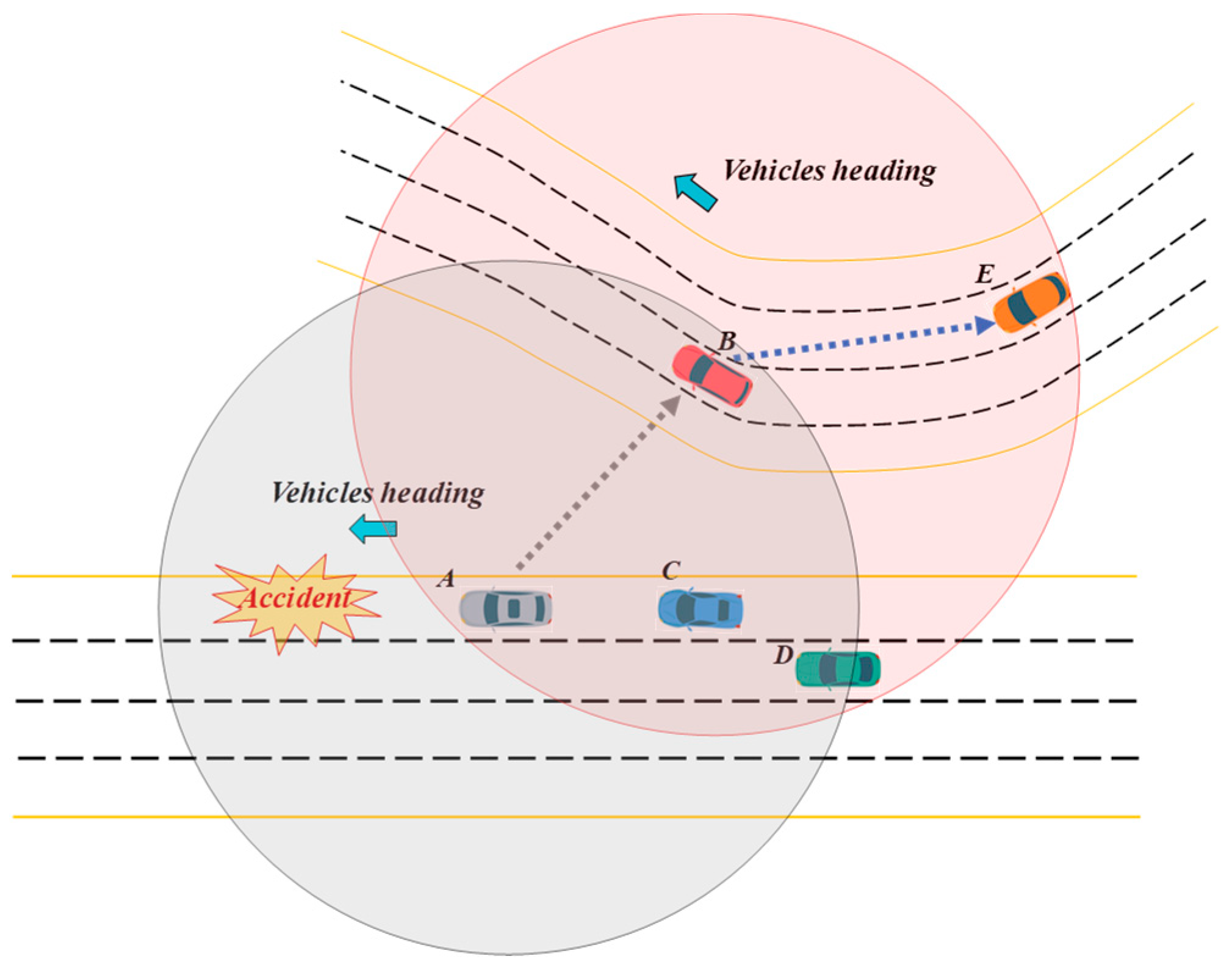
In this approach, the estimation of a vehicle’s next position and destination is the key step to select a relay vehicle. In a city environment, two vehicles may be in the same range, but they may be traveling on different streets. The digital map-based schemes select relay nodes using map information. It is assumed that each vehicle is equipped with a digital map. In Figure 3b, the vehicles of blue, orange, and green colors are moving from right to left. A vehicle in yellow is moving up to down. Suppose that the blue vehicle detects an accident and broadcasts an emergency message to alert other vehicles. The algorithms in Reference [17,18] select the yellow vehicle as a relay. Then, an emergency message will be rebroadcasted by the relay vehicle (yellow color). Since the message is broadcasted by the relay vehicle, the orange car dismisses retransmission due to detection of a duplicate message [9]. In such situations, the green vehicle may miss a vital message. Sofiane Zemoure et al. [25] proposed a broadcast dissemination algorithm that tackles the problem of network overloading. Their method selects multiple forwarders using parameters, such as: the distance between sender and receiver, channel quality, vehicle mobility, and a condition of line-of-sight (LOS) or non-line-of-sight (NLOS); the authors in Reference [26] proposed a method called eMDR, which employs a real map to enhance the performance of message dissemination in VANET. The eMDR uses street map information to ensure reliable data dissemination.

2.5. Network Topology-Based Method

This method is also called a clustering method, where all the vehicles in each cluster are connected to a cluster head (CH). This method represents the combination of distributed and centralized network topologies. While the CH is elected by a distributed algorithm, it controls the communication with its member nodes in a centralized fashion. The CH executes an intra-cluster communication with each cluster member, whereas it uses an inter-cluster communication to disseminate the data to neighbor clusters. In Reference [15], an interesting clustering method based on graph coloring was proposed, which reduces the interference between the clusters. It also provides two levels of bandwidth re-use. Its main contribution is dissemination of local vicinity map (LVM) using inter-cluster communication. The CHs construct LVMs of their cluster by aggregating BSM packets of cluster members. They forward LVMs to other CHs, aiming to enlarge the scope of the LVM. Nishu Gupta et al. [16] proposed a MAC protocol based on mobility aware clustering. It employs time division multiple access (TDMA) to provide fair access to a wireless channel. It is focused on the dissemination of safety-related messages, which requires satisfying stringent quality of service QoS goals.
There are a number of studies on analytical modeling of data dissemination in VANET. Xiaoyun Liu et al. [27] presented a model that describes a data dissemination as a new production adoption process. While analyzing the performance of multi-hop propagation, the authors considered the value of information that decreases as a time passes. In this work, the speed of message dissemination is considered a critical metric for emergency messages, like a traffic accident. The work of Reference [28] conducted the performance analysis of timer-based message dissemination protocols. Its main contribution is the consideration of the delays induced by the timers of the dissemination protocol.
Another interesting study is presented in Reference [29]. In this concept, authors introduced a method that can propagate the warning message in channel alternation period. They highlighted the case where an important warning information is generated during the period that other neighbors are switched in service channels (SCHs). They consider a group of neighbors tuned to the same SCH as one cluster, and within each cluster a coordinator vehicle is selected based on least average separation distance. They proposed a back-off model for emergency message transmission during the SCH interval, and using Markov chain, analysis of end-to-end delay is conducted.
In the simulation stage, we compared our method with algorithms introduced in Reference [17,18]. In Reference [17], authors proposed area-based message dissemination approach that orders the transmission according to the gained additional area that would be covered by potential transmission. Their method integrates a timer and probabilistic area-based transmission; therefore, it is called the APTt algorithm. In Reference [17], authors considered only the gain in new additional area, and they neglected dissemination direction and positional distance. As long as vehicle (receiver) maintains the smallest overlapped area, it becomes a transmitter. This may cause message dissemination in an undesired direction. On the other hand, authors of Reference [18] proposed a distance-based forwarding scheme. According to this method, the farthest (Euclidian distance) node within wireless range of a transmitter obtains the shortest back-off time. In Reference [18], authors highlighted the effect of spurious forwarding phenomenon, and they claimed that their method reduced the effect of this problem. However, this method is only effective in a highway scenario, and this may also propagate the emergency messages towards an undesired direction. In this paper, we propose an LCL-based relay selection scheme. Our approach allows each one-hop neighbor node to calculate its retransmission back-off timer upon receiving the event messages. This back-off timer value is directly proportional to the area that is yielded by a receiver in the upper sector of source’s wireless range. Once the back-off timer of a receiver elapses, it executes retransmission. If during this period it detects the retransmission of the same message by another neighbor, it suppresses the retransmission. Our method considers positional distance and message dissemination direction. Therefore, it provides the smallest back-off timer to the vehicle moving on the same road and aligned to the latest position of transmitter. So, the proposed method can be considered as a timer/delay-based rebroadcast method.

3. Proposed Method

3.1. Systems Model

In this work, we assume that all vehicles in VANET are equipped with an On-Board communication Equipment (OBE), GPS receiver, and other sensors. Each vehicle can communicate either with another vehicle or with a roadside equipment. The motion of vehicles is constrained by the geometry of roads. Therefore, the direction of the vehicles remains unchanged on straight roads. Conversely, the direction may change at intersections or curves. Each vehicle periodically transmits a BSM packet (every 0.1 s), which comprises the position, speed, direction, and other dynamics of the vehicle. The position of a vehicle is specified in a cartesian coordinate system. We also assume that all vehicles have a fixed wireless range and do not support dynamic power alteration mentioned in Reference [1].

3.2. Definition of LCL Algorithm

In VANET based on IEEE1609, a broadcast storm problem aggravates the drawback of poor bandwidth utilization. It creates massive duplicate messages which overload the wireless channel. The overloaded channel in turn causes long delays and collisions in packet transmissions. To address this issue, we propose a novel algorithm that can mitigate a broadcast storm by utilizing the basic information of the receiver and the transmitter. Suppose that a group of vehicles are moving in the same direction, but they are not necessarily located on the same road. A message transmitted by one vehicle may reach many other vehicles in the wireless range of the transmitter, as can be seen in Figure 4. Suppose that vehicle A detects an emergency event and alerts its proceeding vehicles of the danger by broadcasting a warning message. Applying one of the algorithms in Reference [17,18], all receiving vehicles use a timer that triggers retransmission upon expiration of its timer value. Suppose that vehicle B is elected as a relay vehicle by the previous algorithms [17,18]. Such relay vehicles can have the following problem. If vehicle B is on a neighbor road, emergency information of A disseminates to an undesired direction. A similar situation may happen either in urban or in highway scenarios. To address this problem, our method considers a vehicle’s position during the relay selection phase.
In the proposed method, we introduce the notion of a source LCL L L C L , which is a perpendicular line crossing the heading direction of transmitting vehicle V i (presented in Figure 5a). For the sake of simplicity, we explain the concept of the algorithm using only two vehicles, denoted by V i and V j . In Figure 5, V i represents a transmitter, while V j represents a receiver of a multi-hop message. Transmitter V i may also indicate the direction of data dissemination using a specific field in a multi-hop message. In a general highway scenario, it is more effective to propagate messages backward with respect to the vehicle’s moving direction. This way, we can alert the receiving vehicles following behind the transmitter of the imminent danger or emergency ahead of the receiving vehicles. In this particular case, thus, we assume that a message is disseminated from the front vehicle backwards to the rear vehicles. Only in highly segmented network scenario do we utilize the neighbors of the opposite direction to propagate a warning message. In Figure 5a, the lateral crossing line L L C L i of transmitter V i is indicated by a dotted line that is drawn from the center of V i . L L C L i intersects the wireless range of receiver V j at two intercepting points, e and f . The distance between the position of V j and one of the two intercepting points is equal to V j ’s wireless range R , as depicted in Figure 5b. A positional distance d p between V j and the lateral crossing line L L C L i of V i is defined by Equation (1).
d p = { | P i ( y ) P j ( y ) | if H i = 0 °   or   180 ° | P i ( x ) P j ( x ) | if H i = 90 °   or   270 °
Here, H i is a heading angle of the source V i . P i ( y ) and P j ( y ) are the positions of V i   and   V j on y axis, respectively, while P i ( x )   and   P j ( x ) are the positions of V i   and   V j on x axis, respectively. For the sake of simplicity, we assume that d p is always perpendicular to L L C L i of transmitting vehicle V i . A line segment L is defined from point e to point f over L L C L i , as shown in Figure 5c. Then, the length of L can be expressed by Equation (2).
L = 2 R 2 d p 2 .
In Figure 5d, a portion of V j ’s wireless range is segmented by the L . We name this portion an upper sector of the receiver’s wireless range that is partitioned by transmitter’s L L C L i . The proposed technique computes an upper sector for each receiver. Then, the value of this upper sector is used to calculate retransmission back-off timer for corresponding receiver. The value of this area is varied for each neighbor since each neighbor receives the message in different position. The smaller the upper sector area, the shorter the retransmission back-off timer for the corresponding receiver. Within this period, receiver waits for the retransmission of current message by different source. If it detects retransmission, then it cancels retransmission task scheduled earlier (broadcast suppression). As the value of upper sector area is used in calculation of retransmission back-off timer, it should be a smaller to achieve a shorter back-off timer. According to our concept, the value of this area is directly proportional to the value of back-off timer. Therefore, in Figure 5, if receiver V j yields A j that represents smaller area than the produced areas of other neighbors, it becomes relay node for this hop. In this way of selection, the proposed scheme can select the farthest and most aligned neighbor to the transmitter node V i . A value of A j can be computed using different approaches. However, we propose a simpler way for computation of A j .
To convert A j in a simpler form, we define the following parameters: (1) As shown in Figure 6a, there is h distance between the point g and L L C L i of V i . By definition, h represents the difference between R and ( h = R d p ) ; (2). Assuming h is perpendicular to L , we define l 1 and l 2 , which stands for the distances between the points g and e and the points g and f , respectively, as seen in Figure 6b. As line h divides the L into two equal segments, we assume that l 1 and l 2 are equal. Hence, they represent the same value, such as l in Figure 6c. l is defined using Equation (3).
l 2 = L 4 2 + h 2
If we apply Equation (2) and a definition of h in Equation (3), then we obtain the l in the following form.
l = R 2 d p 2 + ( R d p ) 2 = 2 R ( R d p )
The points e , f , and g shape a triangle that accounts for the area A j equivalent to the area A j . The A j may represent an upper sector corresponds to V j , as seen in Figure 6c. Now, A j can simply be specified using Equation (5).
A j = L 4 4 l 2 L 2 = ( R d p ) R 2 d p 2 .
Using Equation (5), A j can be obtained by each receiver, and then it is exploited to compute a unique back-off timer. This unit of time represents the period in which the receiver must hold prior to retransmission of received message. Equation (5), however, may not provide a unique back-off timer for each receiver. In a multilane road or in multiple roads closely constructed to one another, there can be many vehicles that may have the same distance to the source. In this case, these vehicles may consume additional time for competing the channel access. In the worst case, these vehicles may not hear each other. In such a case, they form a hidden terminal problem, which can bring about severe damage on network performance. As illustrated in Figure 7, two nodes receive a broadcast message in similar positions on their moving axis (either P j ( x ) or P j ( y ) ). They are approximately in the same distance from a source vehicle, as presented in Figure 7. Then, in the best case, these two nodes can hear each other, as in Figure 7a, and a back-off timer obtained by each vehicle may result in an equal value. Then, it may lead to the collision due to a synchronized retransmission or it may cause an additional contention time to the wireless channel. In Figure 7a, vehicles C and B receive the message in the distances d y C and d y B , respectively. Since the distances d y C and d y B indicate approximately the same amount, a variation in the value of A B and A C , respectively, obtained by node B and node C will be very small. In the worst scenario, as in Figure 7b, both vehicles cannot hear one another, and these relay nodes may rebroadcast the message at the same time, where all receivers may end up receiving a corrupted packet. Thus, an additional criterion is needed during calculation of the back-off timer for each receiver. In this stage, therefore, we propose to use the receivers’ lateral position information while acquiring the back-off timer. If a receiver’s position is closer to the lane on which a source node is located, then it should rebroadcast the message earlier than other receivers.
b j = d i j l l a n e + 1 .
Here, d i j is distance between the vehicles V i and V j on lateral axis (perpendicular to the moving axis of source). l l a n e is an average width of road lane. In simulation stage, we defined the width of the lane as 3 m in urban scenario and 3.5 m in highway scenario. The value of b j is always one for the receivers moving on the same lane with the source node. Since two vehicles are moving in the lane, the lateral distance between them is less than the width of a lane. Therefore, the first term of Equation (6) becomes zero, and b j becomes 1. As d i j represents a lateral distance between V i and V j , the value of b j for the V j s that are moving on the same road with V i may lay within the range [ 1 ; 1 + w i d t h r o a d / w i d t h l a n e ] . Then, the results of Equations (5) and (6) can be applied in Equation (7) to define a final back-off timer τ j for each receiver V j .
τ j = T m a x × b j A j π R 2 + δ .
Here, T m a x is defines a maximum waiting delay similarly in 17. δ represents a random value that is used to enhance the uniqueness of back-off timer corresponds to each receiver. Equation (7) is timer calculation formula used by the APTt algorithm proposed in Reference [17]. If a potential transmitter obtains a smaller overlapped area, it gets shorter back-off timer. Similarly, in our method, if a transmitter obtains a smaller area in the upper sector, it achieves earlier retransmission of received message. Here, b j aligns the relay node to the precious transmitter. A detailed implementation steps of in proposed algorithm can be seen in Algorithm 1.
Algorithm 1: Lateral Crossing Line Based Forwarding
Input parameters:
V i , V j transmitter and receiver, respectively, M ( V i ) a multi-hop broadcast message received from V i , R the wireless range, d p positional distance between V i and V j , L L C L j LCL of V j , H M direction of message dissemination, l l a n e width of lane, d i j lateral distance between V i and V j
Output:
A unique back off timer τ j for all V j s ;
1/* calculate LCL of each V j */
2FOR each receiver V j of message M ( V i ) DO
3 IF H 90 ° o r   270 ° THEN
4 IF x j x i THEN
5 d p = x j x i ; // source is heading west
6 ELSE IF
7 d p = x i x j ; // source is heading east
8 END IF
9 ELSE
10 IF y j y i THEN
11 d p = | y i y j | ; // source is heading north
12 ELSE IF
13 d p = | y j y i | ; // source is heading south
14 END IF
15 END IF
16 IF d p > D t h r e THEN // in sparse network D t h r e can be zero
17 L j = 2 R 2 d 2 ;  
18 /* triangular area definition for neighbor j */
19 A j = ( R j d p ) R 2 d 2
20 /* definition of lane position */
21 b j = d i j l l a n e + 1 ;
22 /* definition of waiting delay */
23 τ j = T m a x b j A j π R 2 + δ ; // select corresponding
24 ELSE
25 V j   i s   n o t   a l l o w e d   t o   r e t r a n s m i t
26 END IF
27END FOR
Applying our algorithm to the same network in Figure 5, we can analyze each receiver vehicle’s estimated waiting time. Using Figure 8, we are illustrating a similar example scenario, which is presented in Figure 5. In Figure 8, an upper sector area for each neighbor of transmitter node A is indicated in different colors. According to our proposed scheme, vehicle D has a longer positional distance and aligned movement with transmitter node A; hence, it acquires the smallest A j area compared to the other neighbors. The neighbor C is also one of the furthest receivers, but it has larger lateral distance with A and shorter positional distance. Due to this, it obtains a longer retransmission back-off timer when compared with B and D. Using our method, the messages can also be disseminated toward the desired direction without any overhead.

3.3. Message Dissemination in Intersection Area

The direction of a message dissemination in an urban area can be set as a predefined value which indicates a multidirectional propagation of broadcast message. Normally, in an urban environment, vehicles approach an intersection zone from various directions. Taking advantage of this environmental feature, we can propagate the data in multiple directions. We assume vehicles are aware of an intersection zone, using either one of the intersection detection algorithms presented in Reference [30,31]. Prior to each broadcast, transmitter verifies whether its wireless range overlaps any intersection. If an intersection is detected, then, H M i is set to a predefined value that indicates multidirectional data propagation. This value is specially employed to increase the awareness of vehicles regarding any emergency event occurred in urban area. For instance, we used 360 as a multidirectional data propagation value in our implementation.
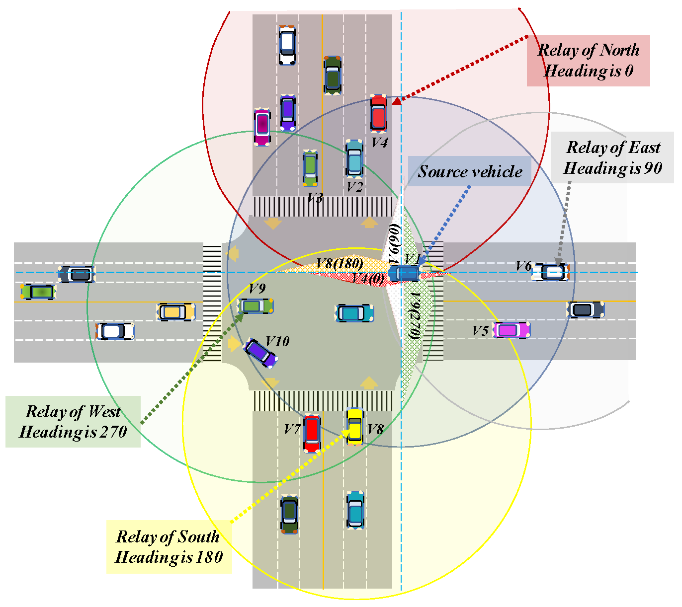
In Figure 9, a multidirectional message dissemination procedure is illustrated. The V1 broadcasts an emergency message within intersection area, where its message is supposed to be disseminated through the multiple directions. Since this special dissemination is required, receivers should consider their position with respect to the LCLs (blue dashed lines) of source vehicle V1. These LCLs are crossing both the P ( x ) and P ( y ) position of the originator of broadcast message V1. Each receiver V j computes two different areas that represent upper sectors A j x and A j y . Afterwards, the values of b j x and b j y are defined for each receiver V j . Then, receiver node V j obtains the back-off timer for two different retransmissions that originate the propagation of event message in two various directions.
For instance, in Figure 9, receiver vehicle V9 can relay the data in both Western ( 270 ° ) and Southern ( 180 ° ) directions. It computes a back-off timer for each direction using the value of corresponding upper sector area A j and lane difference b j . In Figure 9, V9 may give up the retransmission once it detects a duplicate message for the corresponding direction. As seen in Figure 9, vehicle V9 produces the smallest area over the y -axis; thus, it becomes a relay node in which its retransmission originates a data propagation in the Western direction. On the other hand, V10 node may also contend to become a relay for the Western direction, owning to a large distance from V1 vehicle. Here, a lateral distance of V10 is larger than the lateral distance of V9. Due to this factor, V10 obtains a larger b j value, which eventually causes a longer back-off timer. In the proposed scheme, a designation of relay node relies on the back-off value obtained by each receiver using Equation (7). If a node obtains the smallest back-off timer, it designates itself a relay node earlier than other receivers, as aforementioned. Similarly, the V8 vehicle acquires the smallest back-off timer, after which it broadcast the duplicate message in the Southern direction. Thus, in this example, V9 dismisses its scheduled retransmission task due to the detection of a duplicate message from V8. Then, the V9 vehicle executes a rebroadcast of event message in the Western direction, which also dismisses a retransmission task scheduled by the V8 vehicle. Using this distributed concept, each relay node of a corresponding direction conducts self-designation and then propagates the event message in specific directions, as shown in Figure 9.
In order to mitigate duplicate broadcast in intersection zone, we can assign a threshold upon the value of d p . Suppose, in Figure 9, a rebroadcast executed by V9 may not be detected by V2 and V3 vehicles due to long pairwise distance. Then, one of them conducts an undesired retransmission aiming to initiate a data dissemination in the Western direction, where the propagation is already launched by V9. The threshold that we assign on d p may prevent this redundant retransmission. The value of the threshold is specified by the source vehicle upon the analysis of a network density using the one-hop neighbor table. It may increase if density becomes high, whereas if it decreases once, the number of neighbors goes down. The implementation steps of a proposed algorithm in an urban area is presented in Algorithm 2.
Algorithm 2: Relay Selection in Intersection Area
Input parameters:
d x distance to the L L C L i x on X axis, d y distance to the L L C L i y on Y axis, P I Z position details of intersection zone, H j the heading angle of V j , H M i dissemination direction of event message M ( V i ) received from V i , D t h r e x , D t h r e y threshold distance set to limit the number of relay candidates,
Output:
Back off timer values τ j x   and   τ j y ;
8FOR each neighbor node V j of V i DO
9 IF the value of H M i is 360 ° DO
10 d p x = | x j x i | ;
11 d p y = | y j y i | ;
12 END IF
13 IF d p x > D t h r e x THEN // in extreme sparse network, D t h r e = 0
14 c o m p u t e   L L C L i x ,   A j x , τ j x , b j y ;
15 S c h e d u l e ( τ j x , b j y , M ( V i , E i ) ) ;
16 ELSE
17 D i s m i s s   t h e   r e b r o a d c a s t   o f   M ( V i , E i )   o n   X   a x i s
18 END IF
19 IF d p y > D t h r e y DO
20 c o m p u t e   L L C L i y ,   A j y , τ j y , b j x ;
21 S c h e d u l e ( τ j y , b j x , M ( V i , E i ) ) ;
22 ELSE
23 D i s m i s s   t h e   r e b r o a d c a s t   o f   M ( V i , E i )   o n   Y   a x i s ;
24 END IF
25END FOR
26IF   M ( V i , E i ) is received from vehicle V k THEN
27 Dismiss the transmission scheduled to corresponding direction
28END IF

4. Simulation Parameters

We implemented our method in the NS3 simulator. We aimed to obtain performance results regarding various evaluation metrics. We achieved the simulation results for various methods of data dissemination using two different scenarios:
  • A multilane, two directional highway comprises 10 km length. The number of vehicles varies from 10 to 50 vehicle / km . Inter-vehicle distance value follows an exponential distribution, whereas speed of vehicles is uniformly distributed between 10~40 m/s.
  • An urban environment with well-known Manhattan grid (2000 × 2000 m 2 ) comprise 3 × 3 blocks and four-ways intersections [32], as presented in Figure 10. All streets are two-way, with one lane in each direction. Car movements are constrained by these lanes. The direction of each node in every moment will be random. It cannot be repeated in two consecutive movements. Distance between two intersections is around 700 m. Speed of the vehicles is distributed randomly with 0.2 standard deviation. A density of the network varies from 12 and 62 vehicle / km 2 .
We employed a standard MAC and physical layer protocols of IEEE 802.11p, which already exist in the WAVE module of the NS3 simulation tool. The important details regarding the network parameters exploited during the simulation are presented in Table 1. The following are the performance metrics that are considered during the performance evaluation:
  • Average hop-to-hop delay—indicates average delays within each hop during propagation of data up to target distance;
  • Redundancy rate—represents the average number of duplicate messages received in each hop;
  • Relay coverage—estimates the average number of vehicles covered by the relay node in each hop. This criterion shows how effective a selection method of relay node is;
  • A propagation distance—indicates an average distance that a multi-hop broadcast message is delivered within the predefined period;
  • A message delivery ratio within the relevant area—it the percentage of vehicles that received the message in a relevant area. This performance metric is evaluated only in an urban scenario.

5. Performance Analysis and Simulation Results

At first, we obtained simulation results for the proposed scheme and the reference algorithms in Reference [17,18], exploiting a multilane highway mobility model. Figure 11 presents the performance results of all algorithms in terms of the four selected metrics. In Figure 11a, an average hop-to-hop delay performance is shown. Regarding Figure 11a, our method achieves the shortest delay in the network with highest density. Although the method proposed in Reference [17] disables a default CSMA/CA back-off timer during the access to the channel, it performs with a higher delay due to the access collision. As vehicle number on a multilane highway scenario increases, distance between the vehicles decreases. Due to this reason, multiple receivers within the same location may produce a similar new coverage area, which is a main relay selection criterion of Reference [17]. Then, these vehicles may access the channel approximately at the same time, which triggers an access collision. A hop-to-hop delay of Reference [17], however, remains stable regardless of a change in network density. This can be explained with a disabled CSMA/CA back-off timer, which normally contributes more delay in denser network. As in the proposed method, we consider the lane information during the relay selection; therefore, we are able to reduce the possibility of channel access done by the multiple users. On the other hand, the algorithm in Reference [18] performs an increased delay as the density increases in the network. This indicates that a probabilistic, Euclidean distance-based approach is also facing a performance degradation due to a severe channel-access contention. Our method does not disable a conventional MAC layer back-off. As a result, it performs with increasing delay in a denser network scenario.
Figure 11b shows a relay coverage. It is an average number of vehicles that receive the multi-hop message for the first time after each retransmission. While a density sets a lower value, a distance between source and relay becomes decisive criterion during the relay selection. Therefore, in a sparse density scenario, the reference algorithms perform with better relay coverage because a main concept of these algorithms is based on Euclidean distance between sender and receiver. In a denser network condition, however, the position of a vehicle becomes more significant than the inter-vehicle distance. Since we consider the receiver’s lane position and upper sector area, a receiver who represents a more aligned position with the transmitter obtains a shorter back-off timer, even in a denser scenario. Thus, our method results in more relay coverage in a denser network.
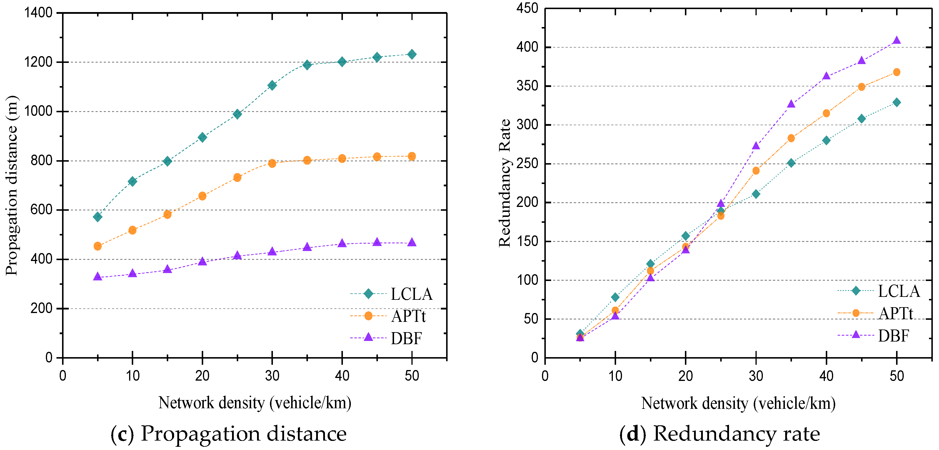
In Figure 11c, the propagation distances are presented for each corresponding data dissemination algorithm. In this experiment, we conducted the test for the average message propagation distance within the predefined packet time-to-live (TTL) period. As a TTL of a message, we set the expected delay period for the warning messages of Situation Ahead (SA) application defined in Reference [14]. During this period, we tested the average propagation distance of a warning message using different approaches. An average propagation distance of the protocol presented in Reference [17] grows when the density of network varies from 10 to 30 vehicle/km. Then, it performs at a stable propagation distance, even when the density continues growing. The proposed algorithm achieves the longest propagation distances for all the cases of network density. On the other hand, it also slows down once the number of nodes in the network becomes 30 vehicle/km. This indicates that the area-based relay selection algorithms provide increasing propagation distance until the density reaches a certain amount. Afterwards, a propagation distance maintains stability. On the other hand, the algorithm of Reference [18] performs slower but constantly increases in propagation distance regardless of network density. It results a lot of collisions since multiple receivers gain approximately the same chance for retransition. The multiple nodes located on adjacent lanes may procures similar distances to the source node. Hence, they acquire the similar forwarding probabilities. Then, a synchronized retransmission occurs frequently, thus becoming a source of access collisions.
Figure 11d compares redundancy rate. It represents an average number of duplicate messages received by nodes. The graph shows a performance of all dissemination algorithms. As aforementioned, in sparse network, the distance is a decisive parameter. In a denser scenario, it is, however, less critical. In our method, a vehicle’s position can cause a significant change in the value of A j and b j . According to Figure 11c, the proposed algorithm performs the least redundancy in the densest scenario, whereas reference algorithms produce a smaller number of duplicate messages in sparse network conditions.
The second experiment was conducted for the urban mobility model, where a vehicle’s movement is constrained by city structure and crossroads. A vehicle’s heading is chosen randomly. In this test, we again increase the number of vehicles from 12 and 62 vehicle / km 2 . We obtained performance results for each dissemination algorithm, with respect to selected metrics in variable density scenarios.
Figure 12 shows simulation results of the proposed algorithm compared with the reference approaches in Reference [17,18]. In Figure 12a, it is shown that our method performs less hop-to-hop delay, but it is not the least. The APTt protocol produces the smallest delay compared with other schemes. Our method performs with slightly more latency, as it uses a conventional back-off period in a MAC layer. In the APTt algorithm, the CSMA/CA algorithm is disabled in the MAC layer. A transmitter does not have to select a back-off counter, and it neglects existing contention in the network. Therefore, whenever the vehicles disseminate the message using APTt algorithm, they immediately retransmit once their timer expires. Another reason can be the multiple retransmissions permitted by our method to relay nodes. As our method lets multiple retransmissions only for the relay nodes, it may thus cause additional contention in the wireless channel. Since emergency messages are important for vehicle safety, we apply multiple retransmission to achieve higher relay coverage, especially in sparse density. Therefore, the proposed method performs an additional delay since multiple relay nodes compete to access a wireless channel.
The algorithm proposed in Reference [18] performed increasing hop-to-hop delay, as observed previously. This time, however, the amount of average delay is shorter than the one shown in Figure 11a. The reason for this behavior can be explained with the urban network structure. As the difference in the position of neighbor vehicles becomes larger (vehicles can move either x or y axis), each neighbor may represent unique retransmission probability, as explained in Reference [18].
Figure 12b illustrates the performance results in terms of relay coverage criterion. As our method allows a multi-directional data dissemination in the intersection zone, it performs with the highest relay coverage. The reference algorithms, however, produced a better performance in a sparse network condition. This again proves a distance-based data dissemination algorithm performs a better relay selection in sparse density.
As we mentioned, the highest relay coverage performance is achieved, however, due to retransmission executed multiple times by selected relay nodes. Therefore, in Figure 12c, our method generates more redundancy than the reference methods in Reference [17,18]. Although the method in Reference [17] also allows twice retransmissions of a broadcast message, it has no additional technique to increase the coverage in intersection area. Thus, it has a lower redundancy rate. During analysis of the simulation result, we discovered that most of duplicate messages are detected outside of a relevant area.
Figure 12d indicates that our algorithm delivers the message up to a longer average propagation distance. In this experiment, we again used a predefined message propagation period, as we explained in Figure 11c. Due to the technique used in an intersection area, our method propagates the message to various directions. The method in Reference [17] also achieves longer propagation distance whenever there is no intersection area. In the intersection area, it struggles propagating the message to further hops, and it suffers from frequent messages lost. Mostly, a message lost is observed due to an access collision done by the multiple relay nodes that produces a similar new coverage area.

6. Conclusions

In this paper, we studied multi-hop propagation of broadcast messages in a distributed vehicular network. We have conducted in-depth simulation analysis of existing dissemination methods and proposed scheme that executes a quick selection of the relay node, regardless of network scenario. In a relay designation phase, our method provides an equal chance for all receivers that contend to become a self-designated relay node. Using the proposed method, a broadcast message can be propagated either in single or in multiple directions. Adding specific information to the header, a transmitter can specify whether the message should be forwarded in multiple directions. Within the wireless range of each receiver, we defined an upper sector area. This area represents a specific segment that is created by LCL of the transmitter. Each receiver node calculates this area considering the LCL of transmitter. A value of this area determined a retransmission time of each receiving vehicle. The smaller the timer, the higher the chance for a receiver to become a relay for the corresponding transmitter. We used a lateral distance between a transmitter and the receivers as an additional factor in the selection of the relay node.
The simulation results were obtained for proposed and reference methods employing both highway, as well as urban, scenarios. According to the results, our method achieved significantly higher relay coverage and message delivery ratio. End to end delay is also reduced by 10 times when compared with reference methods in Reference [18], whereas propagation distance is also elongated around 400 m with compared with Reference [17].

Author Contributions

Conceptualization, O.U. and H.K.; Methodology, H.K.; Software, O.U.; Validation, O.U., H.K.; Formal analysis, O.U.; Writing—original draft preparation, O.U., H.K.; writing—review and editing, H.K.; funding acquisition, H.K. All authors have read and agreed to the published version of the manuscript.

Funding

This research was supported by Basic Science Research Program through the National Research Foundation of Korea (NRF) funded by Ministry of Education with grant number [2017R1D12A710B0p4s032098] and by the Center for Integrated Smart Sensors funded by the Ministry of Science, ICT > Future Planning as Global Frontier Project (NRF-2020M3A6A603280). It was also funded by the KIAT (Korea Institute for Advancement of Technology) grant funded by the Korea Government (MSS: Ministry of SMEs and Startups). (No. S2755555, HRD program for 2019).

Conflicts of Interest

The authors declare there is no conflicts of interest.

References

  1. Intelligent Transport Systems (ITS). Decentralized Congestion Control for Intelligent Transport Systems Operating in the 5 GHz Range; Access Layer Part; ETSI TS 102 687 V1.1.1 (2011-07); European Telecommunications Standards Institute: Valbonne, France, 2011. [Google Scholar]
  2. IEEE Standard for Wireless Access in Vehicular Environment (WAVE); IEEE Vehicular Technology Society Supported by the Intelligent Transmission Systems Committee; IEEE: Piscataway, NJ, USA, 2016; revised draft 2014.
  3. Annual Road Crash Statistics of Association of Safe International Road Travel. Available online: http://asirt.org/initiatives/informing-road-users/road-safety-facts/road-crash-statistics (accessed on 3 November 2019).
  4. Wisitpongphan, N.; Tonguz, O.K.; Parikh, J.S.; Mudalige, P.; Bai, F.; Sadekar, V. Broadcast storm mitigation technique in vehicular ad hoc networks. IEEE Wirel. Commun. 2007, 14, 84–94. [Google Scholar] [CrossRef]
  5. Schwartz, R.S.; Das, K.; Scholten, H.P. Having a Exploiting beacons for scalable broadcast data dissemination in VANETs. In Proceedings of the 9th ACM International Workshop on Vehicular Inter-Networking Systems and Applications, Newcastle, UK, 11–15 June 2012. [Google Scholar]
  6. Department of Transportation. National Highway Traffic Safety Administration 49 CFR Part 571; Docket No. NHTSA-2016-0126, RIN 2127-AL55; Federal Motor Vehicle Safety Standards; V2V Communications, Proposed Rules; National Highway Traffic Safety Administration (NHTSA), Department of Transportation (DOT): Washington, DC, USA, 2016.
  7. U.S. Department of Transportation. Vehicle Safety Communication Applications (VSA-A). In Final Report U.S. Department of Transportation; National Highway Traffic Safety Administration: Washington, DC, USA, 2011. [Google Scholar]
  8. Perkins, C.; Belding-Royer, E.; Das, S. Ad hoc On-Demand Distance Vector (AODV) Routing. RFC 3561. Available online: https://www.rfc-editor.org/info/rfc3561 (accessed on 11 November 2019).
  9. Tonguz, K.O.; Wisitpongphan, N.; Bai, F. DV-CAST: A distributed vehicular broadcast protocol for vehicular ad hoc networks. IEEE Wirel. Commun. 2010, 17, 2. [Google Scholar] [CrossRef]
  10. Viriyasitavat, W.; Tonguz, O.; Bai, F. UV-CAST: An urban vehicular broadcast protocol. IEEE Commun. Mag. 2011, 49, 116–124. [Google Scholar] [CrossRef]
  11. Leandro, A.V.; Boukerche, A.; Maia, G.; Pazzi, R.W.; Loureiro, A. Drive: An efficient and robust data dissemination protocol for highway and urban vehicular ad hoc networks. Comput. Netw. 2014, 75, 381–394. [Google Scholar]
  12. Briesemeister, L.; Hommel, G. Role-Based Multicast in Highly Mobile but Sparsely Connected Ad Hoc Networks. In Proceedings of the 2000 First Annual Workshop on Mobile and Ad Hoc Networking and Computing, Boston, MA, USA, 11 August 2000; pp. 45–50. [Google Scholar]
  13. Khan, A.; Cho, Z.Y. BL-CAST: Beacon-Less Broadcast Protocol for Vehicular Ad Hoc Networks. KSII Trans. Internet Inf. Syst. 2014, 8, 1223–1236. [Google Scholar]
  14. SAE International Standard for Dedicated Short Range Communications (DSRC) Message Set Dictionary J2735_200911. Available online: https://www.sae.org/standards/content/j2735_200911/ (accessed on 27 March 2020).
  15. Yair, A.; Michael, S. Cluster-Based Beaconing Process for VANET. Veh. Commun. 2015, 2, 80–94. [Google Scholar]
  16. Gupta, N.; Prakash, A.; Tripathi, R. Adaptive Beaconing in Mobility Aware Clustering Based MAC Protocol for Safety Message Dissemination in VANET Hindawi. Wirel. Commun. Mob. Comput. 2017, 2017, 1246172. [Google Scholar] [CrossRef] [Green Version]
  17. Alotaibi, M.M.; Mouftan, H.T. Relay Selection for Heterogeneous Transmission Power in VANETs. IEEE Access 2017, 5, 4870–4886. [Google Scholar] [CrossRef]
  18. Salvo, P.; Cuomo, A.B.; Rubin, I. Probabilistic relay selection in timer-based dissemination protocols for vanets. In Proceedings of the 2014 IEEE International Conference on Communications (ICC), Sydney, NSW, Australia, 10–14 June 2014. [Google Scholar]
  19. Panichpapiboon, S.; Pattara-atikom, W. A review of information dissemination protocols for vehicular ad hoc networks. IEEE Commun. Surv. Tutor. 2011, 14, 784–798. [Google Scholar] [CrossRef]
  20. Li, M.; Zeng, K.; Lou, W. Opportunistic broadcast of event-driven warning messages in vehicular ad hoc networks with lossy links. Comput. Netw. 2011, 55, 2443–2464. [Google Scholar] [CrossRef]
  21. Bharati, S.; Zhuang, W. CRB: Cooperative Relay Broadcasting for Safety Applications in Vehicular Networks. IEEE Trans. Veh. Technol. 2016, 65, 9542–9553. [Google Scholar] [CrossRef]
  22. Chaqfeh, M.; Lakas, A. A novel approach for scalable multi-hop data dissemination in vehicular ad hoc networks. Ad Hoc Netw. 2016, 37, 228–239. [Google Scholar] [CrossRef]
  23. Bakhouya, M.; Gaber, J.; Lorenz, P. An adaptive approach for information dissemination in vehicular ad hoc networks. J. Netw. Comput. Appl. 2011, 34, 1971–1978. [Google Scholar] [CrossRef]
  24. Moussaoui, B.; Soufiene, D.; Mohamed, S.; John, M. A cross layer approach for efficient multimedia data dissemination in VANETs. Veh. Commun. 2017, 9, 127–134. [Google Scholar] [CrossRef]
  25. Zemouri, S.; Djahel, S.; Murphy, J. A fast, reliable and lightweight distributed dissemination protocol for safety messages in Urban Vehicular Networks. Ad Hoc Netw. 2015, 27, 26–43. [Google Scholar] [CrossRef] [Green Version]
  26. Fogue, M.; Piedad, G.; Francisco, J.M.; Juan-Carlos, C.; Carlos, T.C.; Pietro, M. Evaluating the impact of a novel message dissemination scheme for vehicular networks using real maps. Transp. Res. Part C Emerg. Technol. 2012, 25, 61–80. [Google Scholar] [CrossRef]
  27. Liu, X.; Yan, G. Analytically modeling data dissemination in vehicular ad hoc networks. Ad Hoc Netw. 2016, 52, 17–27. [Google Scholar] [CrossRef]
  28. Baiocchi, A. Analysis of timer-based message dissemination protocols for inter-vehicle communications. Transp. Res. Part B Methodol. 2016, 90, 105–134. [Google Scholar] [CrossRef]
  29. Eyobu, O.S.; Joo, J.; Han, D.S. CMD: A Multichannel Coordination Scheme for Emergency Message Dissemination in IEEE 1609.4. Mob. Inf. Syst. 2018, 2018, 9876437. [Google Scholar]
  30. Xie, X.; Liao, W.; Aghajan, H.; Veelaert, P.; Philips, W. Detecting Road Intersections from GPS Traces Using Longest Common Subsequence Algorithm. ISPRS Int. J. Geo-Inf. 2017, 6, 1. [Google Scholar] [CrossRef] [Green Version]
  31. Park, J.; Cho, H. Virtual Running Model for Locating Road Intersections using GPS Trajectory data. In Proceedings of the 11th International Conference on Ubiquitous Information Management and Communication, Beppu, Japan, 5–7 January 2017. [Google Scholar]
  32. Katsaros, K.; Dianati, M.; Tafazolli, R.; Kernchen, R. CLWPR—A novel cross-layer optimized position-based routing protocol for VANETs. In Proceedings of the 2011 IEEE Vehicular Networking Conference (VNC), Amsterdam, The Netherlands, 14–16 November 2011. [Google Scholar]
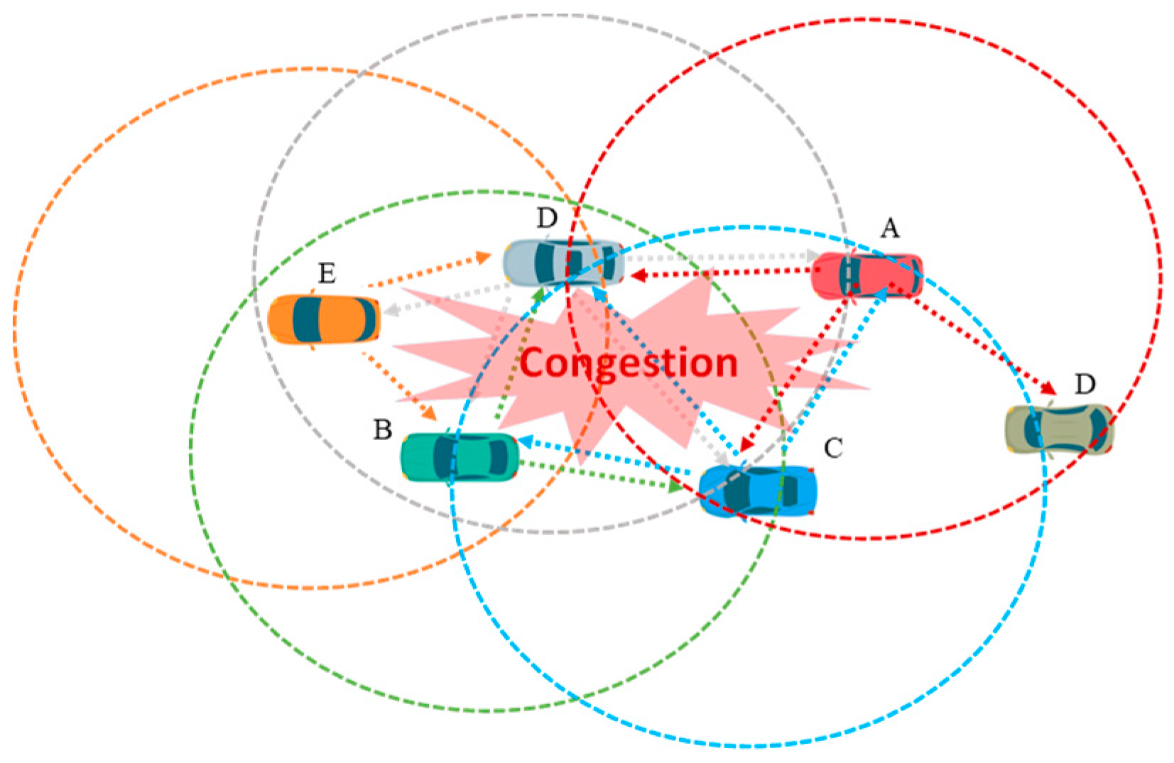
Figure 1. Flooding-based message dissemination procedure.
Computers 09 00025 g001
Figure 2. Various categories of message dissemination protocols in Vehicular Ad-hoc Network (VANET).
Computers 09 00025 g002
Figure 3. Message dissemination cases: (a) determination of sweet spot using; (b) broadcast message dissemination in urban area.
Computers 09 00025 g003
Figure 4. Example of broadcast dissemination process.
Computers 09 00025 g004
Figure 5. Procedures of identification source vehicle V i ’s central line portion covered by receiver vehicle V j .
Computers 09 00025 g005
Figure 6. Procedures for construction a computable form of A j .
Computers 09 00025 g006
Figure 7. Example of broadcast dissemination process using Equation (5): (a) when A and B nodes are located in the same wireless range; (b) when A and B nodes are out of one another’s wireless range.
Computers 09 00025 g007
Figure 8. Selection of relay vehicle using the proposed algorithm.
Computers 09 00025 g008
Figure 9. Broadcast dissemination in urban area.
Computers 09 00025 g009
Figure 10. Three-by-three ( 2000 × 2000   m 2 ) Manhattan grid urban network.
Computers 09 00025 g010
Figure 11. The results of proposed algorithm for a multilane highway scenario. The figures illustrated in these graphs represents an average value of corresponding performance metric for different vehicle number.
Computers 09 00025 g011aComputers 09 00025 g011b
Figure 12. The performance of proposed algorithm for the Manhattan Grid urban scenario. Each graph shows an average value of corresponding performance metric.
Computers 09 00025 g012
Table 1. Simulation parameters.
Network ParametersValue
MAC and PHY parametersIEEE 802.11p
Carrier frequency5.9 GHz
Wireless range250 m
Link Rate6 Mbps
Message size273 bytes
Beacon frequency10 Hz
Simulation time100 s
Highway Mobility
Network scale10 km
Lane width3.5 m
Number of lanes4
Channel fading modelTwo-ray-ground
Urban Mobility
Network scale2000 × 2000 m 2
Lane width3 m
Channel fading modelWINNER II channel model