Article

HfS2 and TiS2 Monolayers with Adsorbed C, N, P Atoms: A First Principles Study

by
Mailing Berwanger
1,†,
Rajeev Ahuja
2 and
Paulo Cesar Piquini
1,*
1
Departamento de Física, Universidade Federal de Santa Maria, Santa Maria, RS 97105-900, Brazil
2
Condensed Matter Theory Group, Department of Physics and Astronomy, Box 516, Uppsala University, S-75120 Uppsala, Sweden
*
Author to whom correspondence should be addressed.
Current address: Instituto Federal de Educação, Ciência e Tecnologia do Rio Grande do Sul, Ibirubá, RS 98200-000, Brazil.
Catalysts 2020, 10(1), 94; https://doi.org/10.3390/catal10010094
Submission received: 26 November 2019 / Revised: 3 January 2020 / Accepted: 3 January 2020 / Published: 8 January 2020
(This article belongs to the Special Issue Towards the Bifunctional Catalysts)

Abstract

:
First principles density functional theory was used to study the energetic, structural, and electronic properties of HfS 2 and TiS 2 materials in their bulk, pristine monolayer, as well as in the monolayer structure with the adsorbed C, N, and P atoms. It is shown that the HfS 2 monolayer remains a semiconductor while TiS 2 changes from semiconductor to metallic behavior after the atomic adsorption. The interaction with the external atoms introduces localized levels inside the band gap of the pristine monolayers, significantly altering their electronic properties, with important consequences on the practical use of these materials in real devices. These results emphasize the importance of considering the interaction of these 2D materials with common external atomic or molecular species.

1. Introduction

Since the discovery of graphene [1], a new ample field of research has opened, the study of two-dimensional layered materials. Graphene exhibits very compelling properties; however, the absence of a band gap in pristine graphene stimulated the search for new materials that can overcome this difficulty, which is essential for applications as in, e.g., electronic devices. Transition metal dichalcogenides (TMD) bulk materials are composed of the stacking of weakly interacting X-M-X (X = chalcogen, M = metal) layers. This makes it feasible to obtain monolayers or few layers of TMD materials through exfoliation and other techniques [2,3]. These two-dimensional materials show remarkable electronic and optical properties that differ from their bulk counterparts [4,5,6,7], exhibiting varied electronic behavior, being found as insulators, semiconductors, metals, semimetals, and superconductors [8].
Among the TMD layered materials, MoS 2 and WSe 2 have received the greatest amount of attention because of their potential integration with current electronic technology [5,9,10]. More recently, studies on other TMD layered materials revealed attractive physico-chemical properties, among them HfS 2 and TiS 2 . Zhao et al. [11] performed ab initio theoretical studies on the electronic and magnetic properties of n-doped (F, Cl, Br, I) and p-doped (N, P, As) 1T-HfS 2 monolayers. Singh et al. [12] used a first principles approach to study the viability of 2D-HfS 2 materials as efficient catalysts for water splitting. Xu et al. [13] fabricated ultrathin HfS 2 phototransitor devices and showed that these materials have the potential for optoelectronic devices. Li et al. [14] used ab initio calculations to show the enhancement of the thermoelectric performance of TiS 2 monolayers under biaxial strain. Das et al. [15] studied the influence of substitutional defects on the S sites as well as S vacancy defects on the electronic, structural, and optical properties on 1T- and 1H-TiS 2 monolayers, and showed that these are promising materials for hydrogen and oxygen evolution reactions in water splitting processes. Samad et al. [16] studied the adsorption and diffusion of monovalent (Li, Na, P) and multivalent (Be, Mg, Ca, Al) metal ions on 1T-TiS 2 monolayers and suggest that Li can be replaced by Mg in high energy density storage batteries based on these 2D materials.
Although the intrinsic properties of pristine TMD layered materials are well characterized, the large scale fabrication of real devices based on these materials needs a deeper understanding of their properties under different conditions. It has been verified, e.g., that TMD layered materials suffer from aging effects [17]. Hence, investigations that explore the interaction of TMD layered materials with external agents, such as common atoms and molecules, are required.
In this work, we use first principles density-functional theory calculations to study HfS 2 and TiS 2 monolayers with adsorbed C, N, and P atoms. We start characterizing the bulk and pristine monolayers of HfS 2 and TiS 2 materials. The structural and energetic features of the TMD monolayers with adsorbed atoms are then described and discussed. We analyze the electronic properties of the interacting systems and show that the electronic properties of the pristine materials are significantly affected by the adsorbents. The results stress the necessity to take into account the influence of external agents when considering applications based on TMD monolayer materials.

2. Methodology

The Density Functional Theory was used to study the structural and electronic properties of the bulk and monolayers of 1T HfS 2 and TiS 2 materials. The exchange and correlation functional was described using the generalized gradient approximation (GGA) [18]. The Bloch functions were expressed in terms of a plane-wave basis set, with a cutoff energy of 500 eV. The projected augmented wave [19] method was used to treat the interactions between the core and valence electrons. Geometry optimizations were carried out using the conjugated gradient method, with the convergence criteria for the total energy and atomic forces being 1 × 10 4 eV and 1× 10 3 eV/Å, respectively. A primitive unit cell, with one transition metal and two sulfur atoms, was used to study the bulk and the pristine monolayers. For the monolayers with adsorbed C, N, and P atoms, the unit cells used were nine times larger, containing 9 Hf/Ti atoms, 18 sulfur atoms, and 1 external adsorbed atom. The average of extensive quantities within the first Brillouin zone was performed using a Monkhorst–Pack sampling of k-points [20]. The number of k-points used in the calculations were 5 × 5 × 5, 9 × 9 × 1 and 5 × 5 × 1 for the bulk, pristine monolayers, and the monolayers with an adsorbed atom, respectively. Once the ground state geometry was obtained, non-spin polarized single-point total energy calculations including the spin–orbit interaction were performed. The calculations for bulk materials were done using the Grimme’s empirical dispersion correction [21].
The GGA/PBE approach for the exchange and correlation functional, as well as the majority of the local and semi-local functionals, is known to give energy gap values that are smaller than experimentally observed. In order to improve the description of the electronic structures, single-point total energy calculations using the GGA-1/2 approach were performed on the GGA/PBE ground state geometries [22].
All calculations were performed using the Vienna Ab Initio Simulation Package (VASP) [23,24].

3. Results and Discussion

3.1. HfS 2 and TiS 2 Materials

The HfS 2 and TiS 2 materials may have different crystallographic forms, or polytypes [8]. For the transition metals of group IV in the periodic table (Ti, Zr, Hf), the most stable structure of MX 2 (X = S, Se, Te) compounds is known as 1T, where the letter T refers to the type of X-M-X stacking of the atomic layers and the symmetry of the bonds formed between the transition metal and its six nearest neighboring chalcogen atoms. This set of atoms will form a prismatic ( D 3 h symmetry) or anti-prismatic ( D 3 d symmetry) trigonal bipyramid. For the materials studied here, the local symmetry is D 3 d . The studied 1T HfS 2 and TiS 2 crystals have a P 3 ¯ m 1 spatial symmetry.
An optimization of the volume and atomic positions of the HfS 2 primitive cell resulted in lattice parameters a = 3.610 Å and c = 5.959 Å, with the distance between nearest neighboring S and Hf atoms being d = 2.540 Å. These results are in good agreement with previous theoretical [25] and experimental [26] studies.
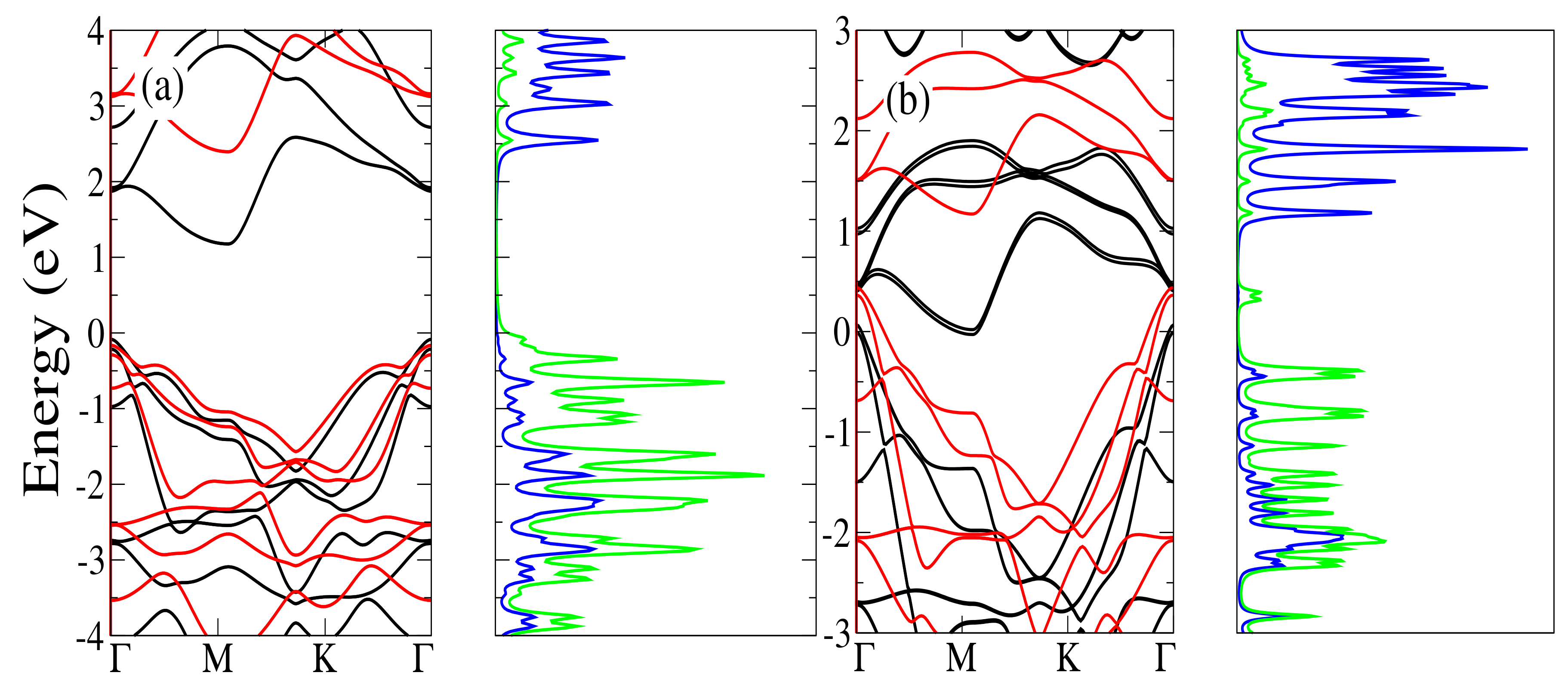
Figure 1a shows the energy band structure obtained for HfS 2 using the GGA (solid black line) and GGA-1/2 (dashed red line) approaches. Both approaches show a very similar band dispersion, with an indirect energy gap Γ M . The GGA calculation finds a Γ M gap of 1.15 eV, while the GGA-1/2 finds 2.38 eV for the same gap. The Γ Γ direct band gap values for the GGA and GGA-1/2 calculations are 1.91 eV and 3.22 eV, respectively. These results can be compared with those by Jiang [27], who found 0.90 eV and 1.96 eV for the indirect gap Γ M using the GGA/PBE and GW calculations, respectively. Results of optical measurements on this material by Greenaway and Nitsche [28] show an indirect band gap of 1.95 eV. The fact that the calculated energy gaps are larger than those experimentally observed can be explained by the fact that in these materials the excitonic effects are quite pronounced [29].
The optimization of the TiS 2 resulted in lattice parameters a = 3.374 Å and c = 5.976 Å, with the distance between nearest neighboring S and Ti atoms being d = 2.419 Å. A comparison with the experimental results of Allan et al. [30], which yield a = 3.407 Å and c = 5.695 Å, shows that there is a 4% discrepancy between the values of c.
The calculated band structure for TiS 2 , using both the GGA and GGA-1/2 approaches, shows that this material is a semimetal, with the top of the valence band at Γ overlapping the bottom of the conduction band at M, as shown in Figure 1b. These results are in good agreement with previous theoretical studies [31].
The agreement between our GGA-1/2 results with more computationally demanding calculations, and also with experimental results, for bulk 1T-HfS 2 and 1T-TiS 2 , allows us to be confident in applying this methodology to the study the monolayered materials.

3.2. 1T HfS 2 and TiS 2 Monolayers

Starting from the equilibrium structures obtained for the HfS 2 and TiS 2 materials in their bulk forms, we isolate monolayers and optimize both its lattice vectors and atomic positions. The large unit cell used for these calculations has a lattice parameter c = 12 Å along the stacking direction, which is enough to avoid the interaction between layers at neighboring cells.

3.2.1. 1T HfS 2 Monolayer

As a result of the optimization process of the 1T HfS 2 monolayer, an increase in the in-plane lattice constant was observed, passing from 3.61 Å in the bulk phase to 3.65 Å in the monolayer form, while the distance between neighboring S and Hf atoms increases from 2.540 Å in the bulk phase to 2.553 Å in the monolayer.
Figure 2a shows the band structures obtained using the GGA/PBE and GGA-1/2 approaches. The dispersion of the electronic bands using both methodologies is similar. The indirect gap value Γ M is 1.259 eV for the GGA/PBE, and 2.557 eV for the GGA-1/2, while the direct gap at Γ is 1.956 eV for GGA/PBE and 3.286 eV for GGA-1/2. The band gap variations between the GGA/PBE and GGA-1/2 are equivalent for both direct and the indirect band gaps, being ≃1.3 eV. These values agree with those obtained by Zhuang and Hennig [32] who found Γ M gap values of 1.27 eV for GGA/PBE and 2.45 eV using the G0W0@PBE approach. Rasmussen and Thygesen [33] determined the direct (at Γ ) and indirect ( Γ M ) gaps values using two different methodologies, LDA and G0W0@LDA. The values found by these authors are E g a p = 1.77 eV (LDA, Γ Γ , E g a p = 1.06 eV (LDA, Γ M ), E g a p = 3.97 eV (G0W0 @ LDA, Γ Γ ) and E g a p = 2.98 eV (G0W0@LDA, Γ M ).
An analysis of the projected density of states (PDOS), not shown here, shows that the level at the top of the valence band is formed by p x and p y orbitals of the two S atoms, where the x y plane is the plane of the monolayer. The level at the bottom of the conduction band, on the other hand, is formed by contributions of the d z 2 and d x z orbitals of the Hf atom.

3.2.2. 1T TiS 2 Monolayer

As in the case of an 1T HfS 2 monolayer, the optimization of the 1T TiS 2 monolayer resulted in an increase of the lattice parameter in the monolayer plane, being a = 3.374 Å in the bulk phase and a = 3.405 Å in the monolayer. The distance between the first neighboring S and Ti atoms also shows a small increase relative to its value in the bulk phase, being 2.419 Å in the bulk and 2.434 Å in the monolayer.
Figure 2b shows the electronic band structure of the 1S TiS 2 monolayer obtained using the GGA/PBE and GGA-1/2 approaches. It is noteworthy that the band gap opens when the GGA-1/2 approach is used. The values of direct ( Γ Γ ) and indirect ( Γ M ) energy gaps are 1.138 eV and 0.780 eV, respectively.
There is a controversy in the literature about the electronic nature of the 1T TiS 2 monolayer, with experimental and theoretical groups characterizing the system either as a semimetal [34] or as a semiconductor [35,36]. In the work of Fang et al. [27], the authors report the 1T TiS 2 bulk material as a semimetal and the monolayer as a semiconductor, with an indirect gap value ( Γ M ) of 1.0 eV, in agreement with our results using the GGA-1/2 method.
As in the case of the 1T HfS 2 monolayer, the density of states near the top of the valence band consists of two levels whose main contributions come from p x and p y orbitals of the S atoms. The levels at the bottom of the conduction band are formed from the d x y orbitals and d z 2 of the Ti atom. These levels at the band edges are unfolded, as well as for the case of the 1T HfS 2 , due to the spin–orbit coupling.

3.3. HfS 2 and TiS 2 Monolayers with Adsorbed Atoms

The adsorption of the C, N, and P atoms on 1T HfS 2 and TiS 2 monolayers was studied using an unit cell that is nine times larger than the primitive cell for the pristine monolayers. The number of atoms in the enlarged cell (without the adsorbents) is 27, with 9 transition metal and 18 chalcogen atoms. Once the adsorbents are introduced into the unit cell (C, N, P), the lattice vectors and the atomic positions are optimized. The initial configurations have the adsorbent atoms placed directly on top of one of the S atoms of the monolayer, at a distance of 1.50 Å.

3.3.1. Energetic and Structural Properties

The structural optimization of the HfS 2 and TiS 2 monolayers with an adsorbed C atom resulted in the structures shown in Figure 3a,b. It can be seen from Figure 3a that the adsorbed C atom migrates to a position where it is equally distant from two S atoms at the top layer, and almost on top of an Hf atom. The C–S distance at this configuration is 1.79 Å, while the C-Hf distance is 2.09 Å. For the TiS 2 monolayer, the C atom will be almost on top of a Ti atom, but in this case the distances to the S atoms at the top layer will not be equal. The two shorter C–S distances are 1.69 Å (shorter than in the HfS 2 monolyaer) and 2.16 Å, with the C–Ti distance being 2.40 Å.
The minimum energy structures found for the monolayers with adsorbed N atom are shown in Figure 3c,d. The geometry optimization shows the adsorbed N atom on a bridge position between one S atom at the top layer and one Hf atom of the monolayer. The defining distances of this equilibrium configuration are N–S = 1.64 Å and N–Hf = 2.02 Å, with a bent angle S–N–Hf = 91.96o. For the N atom on a TiS 2 monolayer, the optimized geometry shows the N atom on top of a S atom at the outermost layer, with an N–S distance of 1.54 Å.
The optimized geometries for the P atom adsorbed on HfS 2 and TiS 2 monolayers are shown in Figure 3e,f. Similarly for the N atom, the adsorbed P atom on the HfS 2 monolayer forms a bridge between a S atom at the outermost layer and one Hf atom of the monolayer. The distances and the bent angle characterizing this configurations are P–S = 2.09 Å, P–Hf = 2.60 Å, and S–P–Hf = 67.16o. For a P atom adsorbed on a TiS 2 monolayer there will be a similarity with the case of an N atom on HfT 2 , with the P atom will be on top of a S atom at the outermost layer, resulting in a P–S distance of 2.02 Å.
The binding energies, E B , of the C, N, and P atoms on the HfS 2 and TiS 2 monolayers are calculated using the following equation:
E B ( M S 2 + X ) = E T ( M S 2 + X ) E T ( M S 2 ) E T ( X ) ,
where M S 2 and X represent the monolayer and the adsorbed atom, respectively. The total energies of the C, N, and P atoms were obtained by spin polarized calculations, in order to correctly describe their atomic spin states.
The binding energies of an X atom on the HfS 2 and TiS 2 monolayers are shown in Table 1. Some general trends can be observed from these data. First, the dependence of the binding energies on the species of the adsorbed X atom follows the order E B ( X ( H ) = C ) > E B ( X ( H ) = N ) > E B ( X ( H ) = P ) . Second, the binding energies for adsorption of an X atom on the TiS 2 monolayer is greater than those for the HfS 2 when X = C or X = P , while the binding energies on HfS 2 are larger than those for TiS 2 when X = N .
Another important energetic characteristic of these 2D systems is the minimum energy necessary to extract an electron, the work function, Φ . The work functions have been calculated by the difference between the Fermi energy and the vacuum level:
Φ = E v a c E F ,
where E v a c and E F and the energies of the vacuum and the Fermi levels, respectively.
The vacuum level is determined as being the constant value of the average electrostatic potential inside the simulation large unit cell far from the materials system. Table 1 shows the calculated work functions for monolayers both pristine and with an adsorbed atom.
From the values shown in Table 1, it can be seen that, while the work functions for TiS 2 monolayers with adsorbed atoms are greater than the corresponding values for HfS 2 , the opposite is observed for the work function of pristine monolayers, with the work function of HfS 2 being greater than that for the TiS 2 . Furthermore, Φ shows the following order for both monolayers: (i) Φ ( M S 2 N ) > Φ ( M S 2 C ) > Φ ( M S 2 P ) , showing that the work functions for the systems with an adsorbed N atom are the largest.

3.3.2. Electronic Properties

In order to analyze the electronic properties of the HfS 2 and TiS 2 monolayers with adsorbed common atoms, we analyze the projected density of states (PDOS) of the studied systems. The calculated PDOS are shown in Figure 4a–f, for the HfS 2 and TiS 2 monolayers with adosrbed C, N, and P atoms, respectively.
The HfS 2 monolayer with an adsorbed C atom shows two filled levels inside the band gap at ∼0.1 eV and ∼1.0 eV below the Fermi energy, see Figure 4a. The main contributions of these levels come from the Hf, S, and C atoms at the adsorption site, with the level closer to the Fermi energy showing a lower contribution from the S atom. The small bandwidth of these levels shows that they are spatially localized, and are due to the bonds formed between the adsorbed C atom and the S and Hf atoms of the monolayer. This system is a semiconductor, with an energy gap of 0.64 eV.
The adsorption of a C atom on the TiS 2 monolayer introduces also two occupied levels inside the band gap of the pristine monolayer at ∼0.1 eV and ∼1.0 eV below the Fermi energy, see Figure 4b. The level deeper in the gap has comparatively equivalent contributions from the Ti, S, and C atoms, whereas the level closer to the Fermi energy has greater contributions from the Ti atom. These are small bandwidth localized levels, located at the adsorption site. The system changes its electronic character, passing from a semiconductor behavior at its pristine form to a metallic character when interacting with an external C atom.
Figure 4c shows the PDOS for the HfS 2 with an adsorbed N atom. It can be seen from this figure that there are three sets of levels inside the band gap of the pristine HfS 2 monolayer. Two of them are occupied with electrons, below the Fermi energy, and one is empty, above the Fermi energy. For the occupied levels in the gap, the greater contributions come from the N atom. For the empty level, the three atomic species have almost similar contributions. The occupied levels in the gap are within ∼0.6 eV below the Fermi energy, while the empty level in the gap is centered at 0.78 eV above the Fermi energy. The system will still have a gap between the occupied and empty levels of ∼0.9 eV.
The adsorption of an N atom on the pristine TiS 2 monolayer turns the system metallic, as shown in Figure 4d. The Fermi energy is at the bottom of a band that can be recognized as the conduction band of the pristine TiS 2 monolayer, and has major contributions from the Ti atoms. The top of the valence band appears 0.70 eV below the Fermi level, with greater contributions from the S atoms. A level with major contributions from the N atom is located 1.0 eV below the Fermi level. The sets of levels appearing below the Fermi energy, from 0.7 to 1.0 eV, can be recognized as originating from the presence of the adsorbed N atom.
The PDOS of Figure 4e shows that when a P atom is adsorbed in the HfS 2 monolayer, a set of occupied levels appear in the energy gap of the pristine HfS 2 monolayer, with greater contributions from the P atom. This set of levels inside the gap have a bandwidth of ∼1.2 eV. The peak of these levels that is closest to the Fermi energy is located 0.17 eV below the Fermi energy. The system is a semiconductor with an energy gap of ∼0.8 eV.
The PDOS for the P adsorbed atom on the TiS 2 monolayer is shown in Figure 4f. It shows a localized occupied level ∼0.5 eV inside the band gap. This system shows a metallic character.
For all the studied cases, the levels inside the band gap have contributions coming from electrons in p-like orbitals of the adsorbed atoms.
The analysis of the PDOS for all the HfS 2 and TiS 2 monolayers with adsorbed C, N, and P atoms show the presence of levels inside the band gap. All the HfS 2 monolayers show a semiconductor behavior. For the TiS 2 monolayers with adsorbed atoms, on the other hand, all systems present a metallic character.
These results show that the interaction with common atoms can significantly alter the electronic behavior of the pristine TMD monolayers, which must necessarily be taken into account when considering using these unique materials for challenging technological applications as solar cells and H 2 generation by water splitting.

4. Conclusions

The energetic, electronic, and structural properties of HfS 2 and TiS 2 have been studied through density functional first principles calculations. The bulk and monolayers are characterized and the adsorption of C, N, and P atoms on the monolayers is investigated. The binding energies reveal covalent chemical interactions between the adsorbent atoms and the monolayers. The work functions of the TiS 2 monolayers with adsorbed atoms are systematically larger than those for the HfS 2 monolayers, contrarily to the pristine cases. A distinctive electronic behavior is observed for the HfS 2 and TiS 2 monolayers with adsorbed atoms. Almost all HfS 2 monolayers+adsorbent atoms present a semiconductor character, with the adsorbents introducing deep occupied levels in the band gap, while the TiS 2 monolayer with adsorbed atoms show a metallic behavior. Overall, the results show that the interaction of HfS 2 and TiS 2 monolayers with common external atoms can strongly influence the electronic responses of these monolayers, which must be taken into account when considering the use of these materials for electronic applications.

Author Contributions

M.B. has done the calculations, the figures and participated in the discussions for the manuscript. P.C.P. has participated in the discussions and analysis of the results and wrote the paper. R.A. has participated in the discussions, analysis of the results and in the writing of the paper. All authors have read and agreed to the published version of the manuscript.

Funding

This work was partially financed by the Coordenação de Aperfeiçoamento de Pessoal de Nível Superior- Brasil (CAPES)-Finance Code 001, and by the Conselho Nacional de Desenvolvimento Científico e Tecnológico (CNPq)—Grant No. 312388/2018-7.

Acknowledgments

The authors acknowledge the computational facilities of the CENAPAD-SP (Centro Nacional de Processamento de Alto Desempenho em São Paulo), UNICAMP project/FINEP-MCT. R.A. acknowledges the Swedish Research Council (VR), Carl Tryggers Stiftelse and Olle Engkvists Stiftelse, Sweden for financial support. The SNIC and UPPMAX are also acknowledged for provided computing resources.

Conflicts of Interest

The authors declare no conflict of interest. The funders had no role in the design of the study; in the analyses, or interpretation of data; in the writing of the manuscript, or in the decision to publish the results.

References

  1. Novoselov, K.S.; Geim, A.K.; Morosov, S.V.; Jiang, D.; Zhang, Y.; Dubonos, S.V.; Grigorieva, I.V.; Firsov, A.A. Electric Field Effect in Atomically Thin Carbon Films. Science 2004, 306, 666–669. [Google Scholar] [CrossRef] [PubMed] [Green Version]
  2. Jirawala, D.; Sangwan, V.K.; Lauhon, L.J.; Marks, T.J.; Hersam, M.C. Emerging Device Applications for Semiconducting Two-Dimensional Transition Metal Dichalcogenides. ACS Nano 2014, 8, 1102–1120. [Google Scholar] [CrossRef] [PubMed] [Green Version]
  3. Radisavljevic, B.; Radenovic, A.; Brivio, J.; Giacometti, V.; Kis, A. Single-layer MoS2 transistors. Nat. Nanotechnol. 2011, 6, 147–149. [Google Scholar] [CrossRef] [PubMed]
  4. Wang, Q.H.; Kalantar-Zadeh, K.; Kis, A.; Coleman, J.N.; Strano, M.S. Characteristics of n- and p-type dopants in 1T-HfS2 monolayer. Nat. Nanotechnol. 2012, 7, 699–712. [Google Scholar] [CrossRef] [PubMed]
  5. Mak, K.F.; Shan, J. Photonics and optoelectronics of 2D semiconductor transition metal dichalcogenides. Nat. Photonics 2016, 10, 216–226. [Google Scholar] [CrossRef]
  6. Mak, K.F.; Lee, C.; Hone, J.; Sham, J.; Heinz, T.F. Atomically Thin MoS2: A New Direct-Gap Semiconductor. Phys. Rev. Lett. 2010, 105, 136805. [Google Scholar] [CrossRef] [PubMed] [Green Version]
  7. Lv, R.; Robinson, J.A.; Schaak, R.E.; Sun, D.; Sun, Y.; Mallouk, T.E.; Terrones, M. Transition Metal Dichalcogenides and Beyond: Synthesis, Properties, and Applications of Single- and Few-Layer Nanosheets. Acc. Chem. Res. 2015, 48, 56–64. [Google Scholar] [CrossRef]
  8. Chhowalla, M.; Shin, H.S.; Eda, G.; Li, L.J.; Loh, K.P.; Zhang, H. The chemistry of two-dimensional layered transition metal dichalcogenide nano sheets. Nat. Chem. 2013, 5, 263. [Google Scholar] [CrossRef]
  9. Liu, H.; Neal, A.T.; Ye, P.D. Channel Length Scaling of MoS2 MOSFETs. ACS Nano 2012, 6, 8563–8569. [Google Scholar] [CrossRef] [Green Version]
  10. Briggs, N.; Subramanian, S.; Lin, Z.; Li, X.; Zhang, X.; Zhang, K.; Xiao, K.; Geohegan, D.; Wallace, R.; Chen, L.Q.; et al. A roadmap for electronic grade 2D materials. 2D Mater. 2019, 6, 022001. [Google Scholar] [CrossRef]
  11. Zhao, X.; Xia, C.; Wang, T.; Dai, X.; Yang, L. Electronics and optoelectronics of two-dimensional transition metal dichalcogenides. J. Alloys Compd. 2016, 689, 302–306. [Google Scholar] [CrossRef]
  12. Singh, D.; Gupta, S.K.; Sonvane, Y.; Kumar, A.; Ahuja, R. 2D-HfS2 as an efficient photocatalyst for water splitting. Catal. Sci. Technol. 2016, 6, 6605. [Google Scholar] [CrossRef]
  13. Xu, K.; Wang, Z.; Wang, F.; Huang, Y.; Wang, F.; Yin, L.; Jiang, C.; He, J. Ultrasensitive Phototransistors Based on Few-Layered HfS2. Adv. Mater. 2015, 27, 7881–7887. [Google Scholar] [CrossRef] [PubMed]
  14. Li, G.; Yao, K.; Gao, G. Strain-induced enhancement of thermoelectric performance of TiS2 monolayer based on first-principles phonon and electron band structures. Nanotechnology 2018, 29, 015204. [Google Scholar] [CrossRef]
  15. Das, T.; Chakraborty, S.; Ahuja, R.; Das, G.P. TiS2 Monolayer as an Emerging Ultrathin Bifunctional Catalyst: Influence of Defects and Functionalization. Chem. Phys. Chem. 2019, 20, 608–617. [Google Scholar] [CrossRef]
  16. Samad, A.; Shafique, A.; Shin, Y.H. Stability, spontaneous and induced polarization in monolayer MoC, WC, WS, and WSes. Nanotechnology 2017, 28, 175401. [Google Scholar] [CrossRef]
  17. Gao, J.; Li, B.; Tai, J.; Chow, P.; Lu, T.M.; Koratkar, N. Aging of Transition Metal Dichalcogenide Monolayers. ACS Nano 2016, 10, 2628–2635. [Google Scholar] [CrossRef]
  18. Perdew, J.P.; Burke, K.; Ernzerhof, M. Generalized Gradient Approximation Made Simple. Phys. Rev. Lett. 1997, 77, 3865. [Google Scholar] [CrossRef] [Green Version]
  19. Blöchl, P.E. Projector Augmented-Wave Method. Phys. Rev. B 1994, 50, 17953. [Google Scholar] [CrossRef] [Green Version]
  20. Monkhorst, H.J.; Pack, J.D. Special points for Brillouin zone integration. Phys. Rev. B 1976, 13, 5188–5192. [Google Scholar] [CrossRef]
  21. Grimme, S. Accurate description of van der Waals complexes by density functional theory including empirical corrections. J. Comput. Chem. 2004, 25, 1463. [Google Scholar] [CrossRef] [PubMed]
  22. Ferreira, L.G.; Marques, M.; Teles, L.K. Approximation to density functional theory for the calculation of band gap of semiconductors. Phys. Rev. B 2008, 78, 125116. [Google Scholar] [CrossRef] [Green Version]
  23. Kresse, G.; Furthmüller, J. Efficiency of ab-initio total energy calculations for metals and semiconductors using plane-wave basis set. Comput. Mater. Sci. 1996, 6, 15. [Google Scholar] [CrossRef]
  24. Kresse, G.; Furthmüller, J. Efficient iterative schemes for ab initio total-energy calculations using a plane-wave basis set. Phys. Rev. B 1996, 54, 11169. [Google Scholar] [CrossRef]
  25. Zhao, Q.; Guo, Y.; Si, K.; Ref, Z.; Bai, J.; Xu, X. Elastic, electronic, and dielectric properties of bulk and monolayer ZrS2, ZrSe2, HfS2, HfSe2 from van der Waals density-functional theory. Phys. Status Solidi B 2017, 254, 1700033. [Google Scholar] [CrossRef]
  26. Hodul, D.T.; Stacy, A.M. Anomalies in the Properties Hf(S2-xTex)1-y and Hf(Se2-xTex)1-y near the Metal-Insulator Transition. J. Solid State Chem. 1984, 54, 438. [Google Scholar] [CrossRef]
  27. Fang, C.M.; de Groot, R.A.; Haas, C. Bulk and surface electronic structure of 1T-TiS2 and 1T-TiSe2. Phys. Rev. B 1997, 56, 4455. [Google Scholar] [CrossRef] [Green Version]
  28. Greenaway, D.L.; Nitsche, R. Preparation and optical properties of group IV-VI2 chalcogenides having the CdI2 structure. J. Phys. Chem. Solids 1965, 26, 1445–1458. [Google Scholar] [CrossRef]
  29. Ugeda, M.G.; Bradley, A.J.; Shi, S.F.; da Jornada, F.H.; Zhang, Y.; Qiu, D.Y.; Ruan, W.; Mo, S.K.; Hussian, Z.; Shen, Z.X.; et al. Giant bandgap renormalization and excitonic effects in a monolayer transition metal dichalcogenide semiconductor. Nat. Mater. 2014, 13, 1091–1095. [Google Scholar] [CrossRef] [Green Version]
  30. Allan, D.R.; Kelsey, A.A.; Clark, S.J.; Angel, R.J.; Ackland, G.J. High-pressure semiconductor-semimetal transition in TiS2. Phys. Rev. B 1998, 57, 5106. [Google Scholar] [CrossRef]
  31. Sharma, S.; Nautiyal, T.; Singh, G.S.; Auluck, S.; Blaha, P.; Ambrosch-Draxl, C. Electronic structure of 1T-TiS2. Phys. Rev. B 1999, 59, 14833. [Google Scholar] [CrossRef]
  32. Zhuang, H.L.; Hennig, R.G. Computational Search for Single-Layer Transition-Metal Dichalcogenide Photocatalysts. J. Phys. Chem. C 2013, 117, 20440–20445. [Google Scholar] [CrossRef]
  33. Rasmussen, F.A.; Thygesen, K.S. Computational 2D Materials Database: Electronic Structure of Transition-Metal Dichalcogenides and Oxides. J. Phys. Chem. C 2015, 119, 13169–13183. [Google Scholar] [CrossRef]
  34. Wu, Z.Y.; Lemoigno, F.; Gressier, P.; Ouvrard, G.; Moreau, P.; Rouxel, J.; Natoli, C.R. Experimental and theoretical studies of the electronic structure of TiS2. Phys. Rev. B 1996, 54, R11009. [Google Scholar] [CrossRef] [PubMed]
  35. Bullett, D.W. Electronic band structure and bonding in transition metal layered dichalcogenides by atomic orbital methods. J. Phys. C Solid State 1978, 11, 4501–4514. [Google Scholar] [CrossRef]
  36. Suga, S.; Tusche, C.; Matsushita, Y.; Ellguth, M.; Irizawa, A.; Kirschner, J. Momentum microscopy of the layered semiconductor TiS2 and Ni intercalated Ni1/3TiS2. New J. Phys. 2015, 17, 083010. [Google Scholar] [CrossRef]
  37. Humphrey, W.; Dalke, A.; Schulten, K. VMD—Visual Molecular Dynamics. J. Mol. Graph. 1996, 14, 33–38. [Google Scholar] [CrossRef]
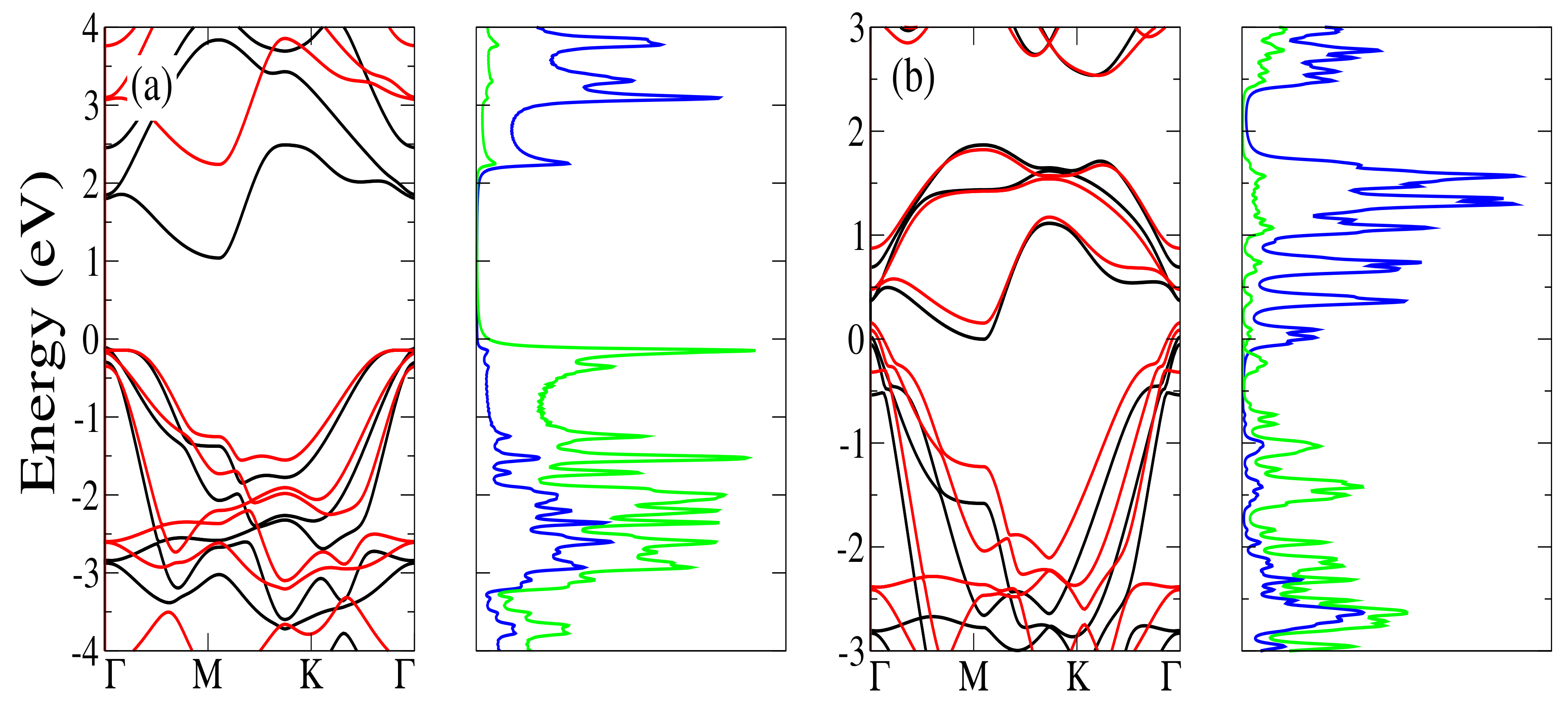
Figure 1. Energy band structures and projected density of states (PDOS) of (a) 1T HfS 2 and (b) 1T TiS 2 bulk crystals. In the band structures the black solid (red dashed) lines represent the results obtained using the GGA/PBE (GGA-1/2) approach. In the PDOS, the blue and green lines represent the transition metal and the sulfur atoms, respectively.
Catalysts 10 00094 g001
Figure 2. Energy band structure and projected density of states (PDOS) of monolayers of (a) HfS 2 , and (b) TiS 2 . In the band structures, the black solid (red dashed) lines represent the energy bands obtained using GGA (GGA-1/2) approach. In the PDOS, the blue and green lines represent the transition metal and the sulfur atoms, respectively.
Catalysts 10 00094 g002
Figure 3. Top view of the optimized structures for the adsorption of (a) a C atom on HfS 2 , (b) a C atom on TiS 2 , (c) an N atom on HfS 2 , (d) an N atom on TiS 2 , (e) a P atom on HfS 2 , and (f) a P atom on TiS 2 monolayer. The brown, blue, and yellow dots represent the Hf, Ti, and S atoms, respectively. The small dark brown, blue, and gray dots (one per panel) represent the C, N, and P adsorbed atoms, respectively. It should be noted that the S atoms are distributed around the transition metal atoms in a D 3 d symmetric arrangement, with three of them in a plane above and other three of them in a plane below the plane of the transition metal atoms. Some of the sticks representing the bonds between the adsorbed atoms and the atoms at the 2D structure are absent because the distances between these adsorbed atoms and the atoms at the 2D structure are greater than the default values established in the Visual Molecular Dynamics (VMD) package [37].
Catalysts 10 00094 g003
Figure 4. Projected density of states for the monolayers of (a) HfS 2 with an adsorbed C atom, (b) TiS 2 with an adsorbed C atom, (c) HfS 2 with an adsorbed N atom, (d) TiS2 with an adsorbed N atom, (e) HfS 2 with an adsorbed P atom, and (f) TiS 2 with an adsorbed P atom.
Catalysts 10 00094 g004
Table 1. Calculated binding energies, E B , and work functions, Φ , in eV, of the HfS 2 and TiS 2 monolayers with adsorbed atoms.
Adsorbed SpeciesE B Φ
HfS 2 TiS 2 HfS 2 TiS 2
8.578.26
C2.823.096.897.53
N2.081.847.357.61
P1.251.496.807.22