Article

In Situ Thermal-Stage Fitted-STEM Characterization of Spherical-Shaped Co/MoS2 Nanoparticles for Conversion of Heavy Crude Oils

by
Manuel Ramos
1,*,
Félix Galindo-Hernández
2,
Brenda Torres
3,
José Manuel Domínguez-Esquivel
4,* and
Martin Heilmaier
5,*
1
Departamento de Física y Matemáticas, Instituto de Ingeniería y Tecnología, Universidad Autónoma de Cd. Juárez, Avenida del Charro 450 N, Cd. Juárez C.P. 32310, Mexico
2
Departamento de Ciencias Experimentales, Universidad Nacional Autónoma de México (UNAM), Av. Canal de San Juan Esq. Sur 24, Col. Tepalcates, Iztapalapa, Ciudad de México C.P. 09210, Mexico
3
Department of Chemistry and Biochemistry, 500 W. University Ave., Physical Science Bldg. Rm 207C University of Texas at El Paso, El Paso, TX 79968, USA
4
Instituto Mexicano del Petróleo, Eje Central Lázaro Cárdenas Norte 152 Col. San Bartolo Atepehuacán, Ciudad de México C.P 07730, Mexico
5
Institut für Angewandte Materialien-Werkstoffkunde (IAM-WK), Karlsruher Institut für Technologie, Engelbert-Arnold-Strasse 4, 76131 Karlsruhe, Germany
*
Authors to whom correspondence should be addressed.
Catalysts 2020, 10(11), 1239; https://doi.org/10.3390/catal10111239
Submission received: 17 September 2020 / Revised: 13 October 2020 / Accepted: 22 October 2020 / Published: 27 October 2020
(This article belongs to the Special Issue Catalytic Hydroprocesses and Oil Refining)

Abstract

:
We report the thermal stability of spherically shaped cobalt-promoted molybdenum disulfide (Co/MoS2) nano-catalysts from in-situ heating under electron irradiation in the scanning transmission electron microscope (STEM) from room temperature to 550 °C ± 50 °C with aid of Fusion® holder (Protochip©, Inc.). The catalytic nanoparticles were synthesized via a hydrothermal method using sodium molybdate (Na2MoO4·2H2O) with thioacetamide (CH3CSNH2) and cobalt chloride (CoCl2) as promoter agent. The results indicate that the layered molybdenum disulfide structure with interplanar distance of ~0.62 nm remains stable even at temperatures of 550 °C, as observed in STEM mode. Subsequently, the samples were subjected to catalytic tests in a Robinson Mahoney Reactor using 30 g of Heavy Crude Oil (AGT-72) from the golden lane (Mexico’s east coast) at 50 atm using (ultrahigh purity) UHP hydrogen under 1000 rpm stirring at 350 °C for 8 h. It was found that there is no damage on the laminar stacking of Co/MoS2 with temperature, with interlayer spacing remaining at 0.62 nm; these sulfided catalytic materials led to aromatics rise of 22.65% and diminution of asphaltenes and resins by 15.87 and 3.53%, respectively.

Graphical Abstract

1. Introduction

Layered metal sulfides such as molybdenum disulfide (MoS2) have been extensively used as catalytic materials in oil refineries for removal of noxious impurities including sulfur, nitrogen compounds and metals like Ni and V, mainly by means of hydrodesulfurization (HDS) and hydroprocessing (HDP) [1]. Previous studies indicate that the catalytic activity of MoS2 is enhanced by certain metal promoters like cobalt and nickel, as described by Chianelli et al. [2] to create the so-called CoMoS or NiMoS phases as coined by Topsøe et al. [3]. The crystallographic structure of MoS2 is characterized by a sandwich-like stacking of layers with van der Waals-type chemical bonds between S-Mo-S along the c-direction, with an interlayer distance of 0.62 nm, which makes this particular material ideal for high temperature and tribology engineering applications. More recently, it has been considered as a semiconductor electron transport material for electronic devices [4,5]. The location of metals that are promoters responsible for enhancing metallic “brim” or “edge” sites have been discussed in the literature [6,7] and some studies were made by X-ray absorption near edge structure (XANES) [8], scanning tunneling microscopy (STM) [9] as well as high-resolution transmission electron microscopy (HRTEM) [10]. A series of observations to locate the position of cobalt promoters have been described by Deepak et al., who used Z-contrast in STEM mode for determining a bond distance of 2.24 Å between W-Co-W-Co-W, atoms at the laminar edge of WS2 (which is a material with a structure alike to MoS2) thus demonstrating the location of these promoters [11]. Moreover, the “in-situ” operando HRTEM techniques made it possible to achieve experimental observations that relate it to crystal growth as described by Hansen et al.; these authors directly imaged laminar MoS2 phase formation from MoO3 in an atmosphere of H2S:H2 = 1:9 (0.8 mbar) at 690 °C, with the use of an environmental TEM holder [12]. Ramos et al. performed a study at the carbon grid level on “in-situ” TEM carburization effects on fresh Co/MoS2 unsupported catalyst at the temperatures range of 350 to 450 °C, thus determining bending curvatures of the MoS2 layers that are due to carbon deposits and replacement of sulfur atoms at the reactive edges of the MoS2 platelets. This resulted in a stabilized MoS2−CX phase that presents texturally stabilized sulfide particles, thus keeping a crystallite size smaller and less stacked, which is in agreement with data reported elsewhere [13,14]. Recently, an electron tomography study determined significant fractal aspects that are related to porosity in cobalt-promoted MoS2 in spherically shaped nanoparticles [15], which is coincident with previous work reported by Yin et al. for MoS2-type catalysts [16]. Herein, we present an “in-situ” heating STEM study whose purpose was to determine the structural stability of Co/MoS2 catalyst along with “ex-situ” catalytic performance for upgrading heavy crude oils from the golden lane (Mexico east coast, well AGT-72). These crude oils have high viscosities of about 25·103 cP at room temperature and a gravity of less than 13 oAPI, with asphaltene content higher than 20%. Their mean asphaltene structure was reported recently for the first time [17], thus, the purpose of this work was to characterize the structural features of the active-proven layered MoS2 catalysts by STEM fitted with a thermal stage. For this, off-line catalytic reaction was performed in parallel to prove their activity for the hydroprocessing of heavy feedstocks [18,19].

2. Results and Discussion

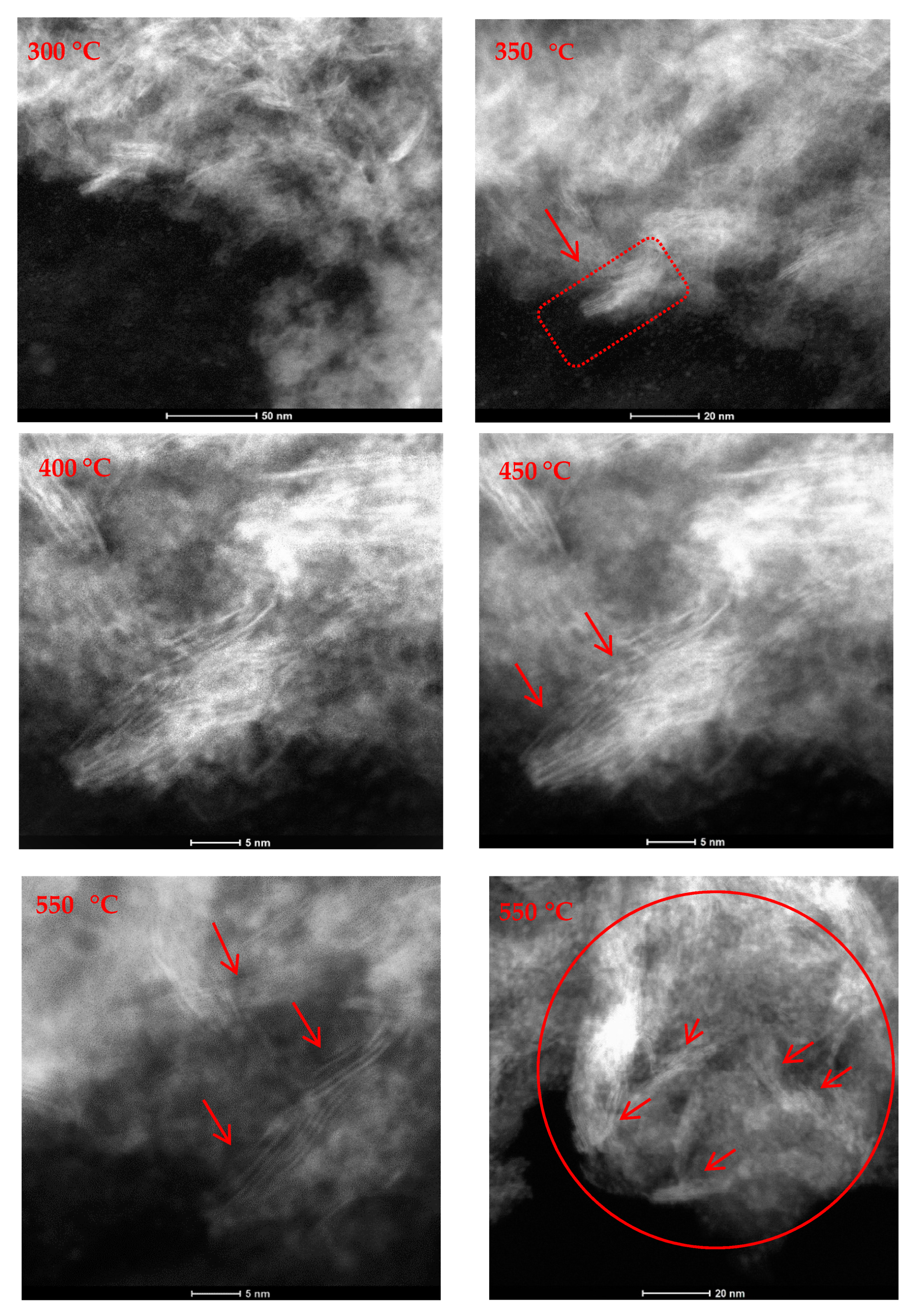
2.1. In-Situ Scanning Transmission Electron Microscopy (STEM)

Albiter et al. [15] show SEM micrographs (geometry nanorods) for MoS2 samples before and after 5 h of reaction at 350 °C during HDS reaction.By comparing between micrographs, Albiter et al. show important textural changes for MoS2 samples after 5 h of reaction, as well as a decrease in specific surface area of 56% for the MoS2 samples synthetized at 400 °C and 74% for those synthetized at 700 °C. In addition, a decrease in the catalytic activity (24%) and selectivity (39%) was observed. Taking these results into account, STEM images were performed and used as references in order to assess the textural effects over the sample synthetized by the method described above. The sample was subjected to in-situ heating from room temperature up to 550 °C. The images from in-situ heating STEM experiments indicate that the sample was texturally stable up to 550 °C, with no diffusion or evaporation observed. Figure 1 presents two STEM images taken at room temperature together with the heating profile used during the experiments. At room temperature, it was possible to observe some porosity typical of the Co/MoS2 spheres as reported by Ramos et al. [16] and laminar dispersed structures (needle-like) corresponding to MoS2 as are indicated by red arrows in Figure 1, as described in detail by Vollath et al. [17] for MoS2 nanocrystals (Figure S1). This result allows us to suggest that if the hydroprocessing reactions are carried out above 350 °C, and there are changes in the activity and selectivity of the reaction, these would be a consequence of non-textural factors.
During heating stages at a ramp rate of 150 °C/min, as indicated in Figure 2, it was possible to determine the structural stability at 300 °C, 350 °C, 400 °C, 450 °C, 500 °C and 550 °C. It was found that there is no damage on the laminar stacking of Co/MoS2 with temperature, which is of interest for catalyst design for in-situ crude oil upgrading, as described by Pereira-Almao et al. [20]. Furthermore, it was possible to observe the structure stability of cobalt-promoted MoS2 layers, as indicated by the red arrows over atomic fringes that are characteristic of the ~0.62-nm interlayer distances typical of van der Waals solids, as described by Chianelli et al. [21].

2.2. In-Situ Hydrodesulfurization Activity

The HDS process is most commonly used to obtain low sulfur fuels, i.e., ultra-low-sulfur-gasoline (sulfur content < 15 ppm). Thus, the proof of concept for the “in-situ”-catalytic test was performed using a heavy crude oil (AGT-72) from “The golden Lane” using a Robinson Mahoney-type reactor with a loading of 30.0 g crude oil AGT-72 and 0.3 g of Co/MoS2 catalyst. The reaction was carried out with ultra-high purity hydrogen at 50 atm and 350 °C for 8 h. HDS results show that the catalyst reduces the sulfur content of crude oil from 5.1% to 4.8%, despite the refractory species present in the Heavy Crude Oil-AGT-72. The catalytic nanoparticles in our study are aimed for applications in oil recovery into oil reservoirs [20,21,22,23]; however but some challenges persist such as: (i) a better crude oil–catalyst mixing, (ii) a close effective H2/hydrocarbon ratio and (iii) the influence or role of impurities and sulfidation as described by Afanasiev [24]. Mainly, for an optimal catalytic performance for cobalt- or nickel-promoted MoS2 catalyst.

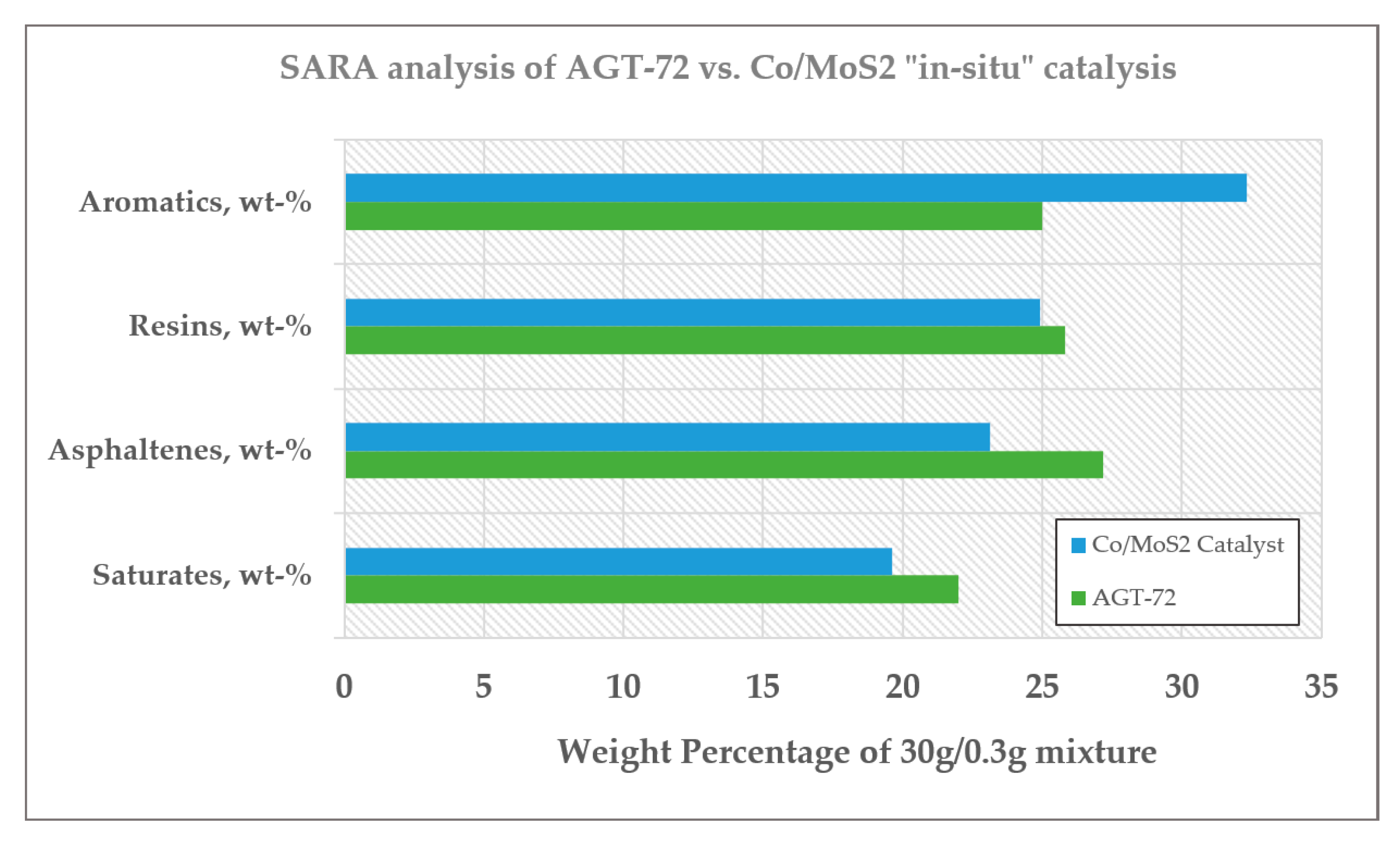
Saturates, Asphaltenes, Resins and Aromatics (SARA) Analysis

Results from the SARA analysis are presented in Figure 3, which is used as the metrics to assess the conversion and selectivity as well as to establish the quality of the reaction products. The results after reaction showed a significant decrease in the original amount of asphaltenes, as displayed in Table 1, along with a slight decrease in percentage of resins, while a substantial increase in aromatics content is verified, which hold the asphaltenes micelles in suspension [25]. As reported before, resins have a strong tendency to associate with asphaltenes due to their high polarity, thus, acting as a protective shield of asphaltenes [26]. For the present case a stable and less viscous crude oil remains after the hydrotreatment with CoMoS2; the instability index (CII) developed by Yet et al. [27] was used by means of the Equation (1), for measuring the asphaltenes deposition potential of hydrotreated AGT-72. Our results give a CII value around 0.7 after CoMoS2 in situ treatment, which confirms a stable product, whereas CII results with values of CII higher than 0.9 are considered as unstable. These results show the increase in stability when the AGT-72 crude oil undergoes hydrotreatment with Co/MoS2 catalysts.
          CII = Saturates +   Asphaltenes Aromatics + Resins
On the other hand, the increased amount of aromatics content (wt-%) from 25.0 to 32.0 may contribute to a higher-octane number, together with isoparaffins [28]. It is clear from our data that aromatics, resins, asphaltenes and saturates proportions, i.e., SARA, are modified after interaction of AGT-72 with Co/MoS2 catalyst, which is a basic proof of the concept for the potential use of cobalt-promoted MoS2 spherically shaped nanoparticles for in-situ heavy oil upgrading [16,22] at a microscopic level.

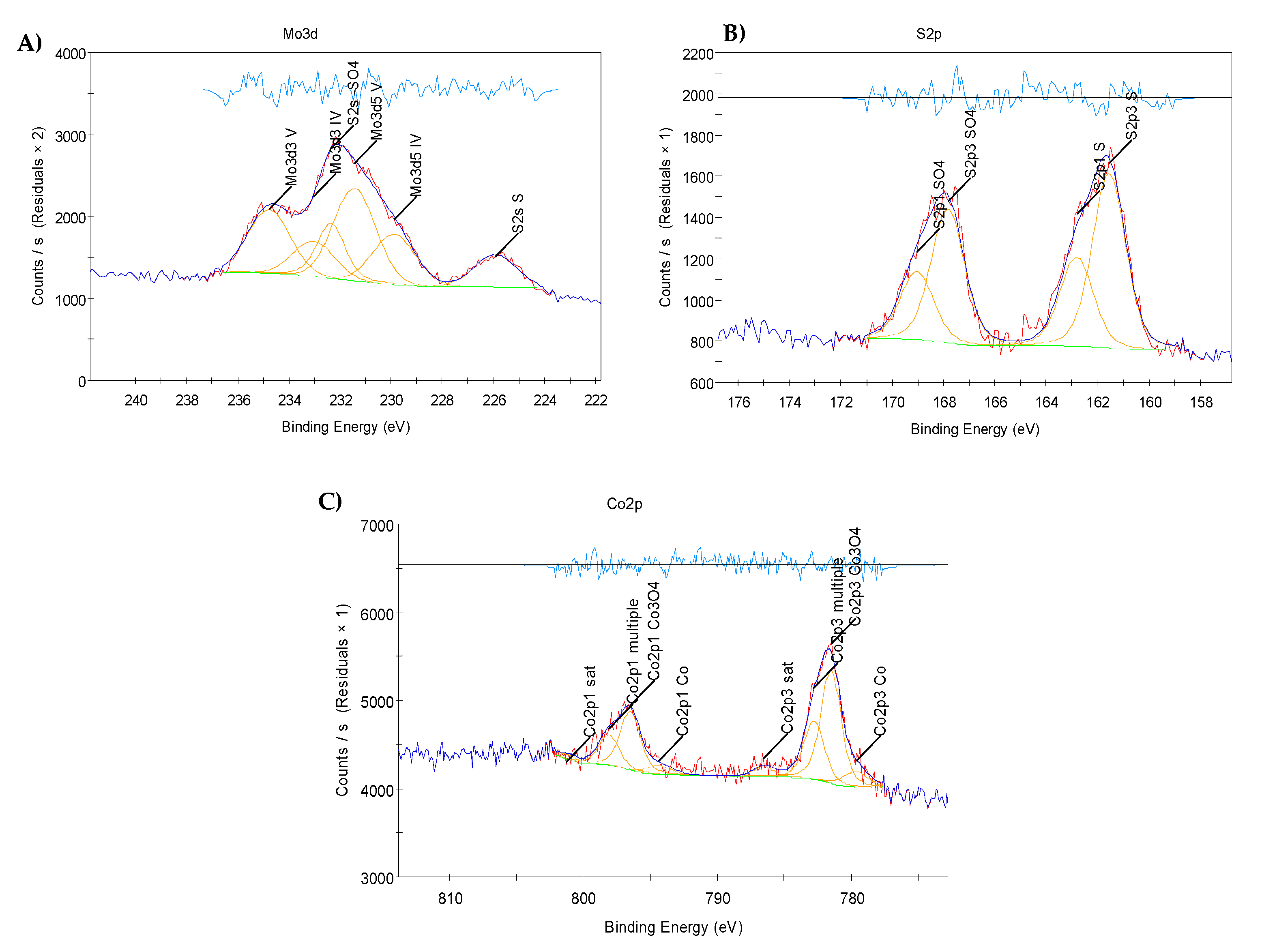
2.3. X-Ray Photoelectron Spectroscopy (XPS) Results

Cobalt promoters were not identified by STEM as reported earlier by Deepak et al. [11], partially due to their low concentration and dispersion located along the crystallite edges, as indicated by Zhu et al. [7]. Thus, in this work, the fresh catalyst was focused on the analysis by X-ray photoelectron spectroscopy (XPS) of the chemical environment around the atoms present on the top surface layers. Figure 4 indicates the presence of molybdenum 3d3/2 (232eV), sulfur 2p3/2 (168eV) and cobalt 2p3/2 (782eV) that was verified, in agreement with Joe et al. [21].

3. Materials and Methods

3.1. Co/MoS2 Catalyst Preparation

The catalyst was synthesized by mixing 3 mmol of sodium molybdate (Na2MoO4·2H2O) (Sigma Aldrich, Inc. 2033 Westport Center Dr, St. Louis, MO 63146, USA) and 9 mmol of thioacetamide (CH3CSNH2) (Sigma Aldrich, Inc. 2033 Westport Center Dr, St. Louis, MO 63146, USA), followed by the addition of 30 mL of deionized water and 0.5 g of sodium silicate (Na2SiO3·9H2O); the resulting solution was kept under vigorous stirring for 30 min. The pH of the solution was adjusted to 6.0 using a 12 M hydrochloric acid (HCl) solution, then 0.50 g of cobalt chloride (CoCl2) was added to the solution, which turns into a purple color, then it was placed into a Parr© reactor and set at a temperature of 220 °C for 4 h, followed by slow cool down. The catalyst was washed using Sodium Hydroxide (NaOH) 1 M to remove possible residues and was dried at 200 °C in autoclave, as described by Ramos et al. [15].
The stoichiometry of the reaction is the following:
6CoCl26H2O + 12Na2MoO4 + Na2SiO3 + 26HCl H4SiCo6Mo12O40+26NaCl + 47H2O + 6Cl2
CH3CSNH2 + 2H2O → CH3COOH + NH3+H2S
H4SiCo6Mo12O40 + 27H2S → 12Co0.5MoS2+H2SiO3 + 3H2SO4 +25H2O

3.2. Catalytic Activity in the Conversion of Golden Lane Crude Oil

The activity test was carried out in a Robinson Mahoney Reactor (Parker, Inc. 8325 Hessinger Dr., Erie, Pennsylvania 16509 USA) using 30 g of Heavy Crude Oil, i.e., labelled as AGT-72, and 0.3 g Co/MoS2 catalyst that are placed in a stainless-steel basket to obtain an oil/catalyst ratio of 10/1 wt/wt. The reaction system was adjusted to 50 atm using ultra-high purity hydrogen (UHP), the stirring rate and temperature were 1000 rpm and 350 °C during reaction time of 8 h, respectively. The pressure was controlled at 100 kg/cm2 during the reaction. The hydrotreated crude oil was analyzed to determine the composition of the lumps by means of SARA analysis, i.e., saturates, aromatics, resins and asphaltenes.

3.3. SARA Analysis

The asphaltenes were precipitated with n-heptane following the American Society for Testing and Materials (ASTM) D3279 method and the remaining fraction was separated following the ASTM 2700 method, thus obtaining the concentration of resins, aromatics and saturates of both crude oil and the hydrotreated (i.e., after conversion) crude oil. The identification of some individual compounds and gaseous products was made by gas chromatography coupled to mass spectrometry model PerkinElmer© Claurus 590TM (GC–MS, PerkinElmer, Norwalk, CT, USA).

3.4. In-Situ STEM

Approximately 0.05 g of the (catalyst) black precipitate was dispersed in ethanol to make an almost transparent solution, from which one drop was placed into the Fusion® sample holder chip from Protochip© (3800 Gateway Centre Blvd #306, Morrisville, NC 27560, USA) and it was dried at room temperature. Observations were made on a FEI® model Titan© STEM (Hillsboro, OR, USA) unit, fitted with a charge coupled device (CCD) camera, and it was operated at 300 keV in STEM-mode, with an extraction voltage of 4500 V, Gun Lens 6, Camera Length 0.195 m, Spot size 7, data size 1024 pixels × 1024 pixels. The heating rate was set at 150 °C/min starting from room temperature; the first step was at 300 °C, at different magnifications upwards and downwards; continuing to the next temperature step was followed (350 °C, 400 °C, 450 °C, 500 °C, 550 °C, respectively, keeping the ramp at 150 °C/min). The long acquisition time needed for single frames was in the range of 5–10 s and in general, if the sample drift was not too high then a drifting correction was possible, as well as the stability of the Fusion® holder as presented in (Figure S2).

3.5. X-Ray Photoelectron Spectroscopy (XPS)

XPS was performed in a Thermo-VG Scientific model Escalab-250 equipment (ThermoFisher® Scientific, Waltham, MA, USA) Company, City, State Abbr. and Country.) at ultra-high vacuum (10−9 mbar) conditions. The data sets were acquired with monochromatic Al radiation source (1486.6 eV), binding energies (BE) were corrected using C 1s (284.6 eV). All data were analyzed with XPS Peak 4.1©, applying a Shirley background subtraction and Gaussian–Lorentzian deconvolution parameters.

4. Conclusions

A combined study about thermal performance by using in-situ heating-stage-STEM, XPS and a micro-reaction characterization off-line to determined that the catalytic material is composed by Co/MoS2 spherically shaped aggregates catalytic nanoparticles (see supplementary information Figure S1A), with an average size of 2.8 microns (S1) were structural stable even at temperatures of 550 °C in accordance with imaging, turbostratic or layers bending were not observed at those elevated temperatures, as diffraction patterns indicate d(001) = 0.62 nm corresponds to c-axis stacking remains as presented in Figure S3. Furthermore, catalytic experiments using Mexican crude oil (AGT-72) showed partial oil upgrading when a mixture of catalytic material was used; these transition metal sulfides materials led to aromatics rise of 22.65% and the diminution of asphaltenes and resins by 15.87 and 3.53%, respectively.

Supplementary Materials

The following are available online at https://www.mdpi.com/2073-4344/10/11/1239/s1, Figure S1: (A) Scanning electron micrograph of spherical shape MoS2 showing homogeneous size. (B) Sphere type morphology of platelet aggregates of MoS2 layers. (C) Experimental STEM-dark field image of Co/MoS2., Figure S2: Collage of pictures of sample holder Fusion© used to perform heating in-situ STEM to determine thermal structural and crystallographic stability of Co/MoS2 catalytic samples., Figure S3: Diffraction patterns obtained during in-situ heating of spherical shape Co/MoS2 particles, one can observed that d(002) = 0.62 nm remains at any moment, indicating that stacking of layers remain and not much crystallographic variation was observed even at elevated temperatures of 550 °C.

Author Contributions

F.G.-H., B.T. and M.R. prepared the samples using hydrothermal chemistry methods. M.R. performed in-situ heating STEM experiments with the support of TEM-experts at the user facility KNMF. J.M.D.-E. provided the XPS analysis and catalytic test with Mexican Crude Oil. M.H., J.M.D.-E. and M.R. prepared the manuscript conceptualization, writing/editing, data processing. All authors have read and agreed to the published version of the manuscript.

Funding

Mexican Science Council (CONACyT-México) and Energy Ministry (SENER) under solicitation grant FSCSEH No. 177077 (IMP project Y.61006). Karlsruhe Nano Micro Facility (KNMF) of Karlsruhe Institute of Technology (KIT) for STEM measurements (proposal ID: 2018-020-023709).

Acknowledgments

Authors thank Instituto Mexicano del Petróleo for usage of laboratory facilities. To Karlsruhe Nano Micro Facility (KNMF) of Karlsruhe Institute of Technology (KIT) for usage of electron microscope unit and Dr. D. Vinga Szabo for technical assistance on in-situ STEM measurements. Manuel Ramos thanks the Universidad Autónoma de Ciudad Juárez for sabbatical travel award support 2018–2019.

Conflicts of Interest

The authors declare no conflict of interest.

References

  1. Chianelli, R.R.; Berhault, G.; Torres, B. Unsupported transition metal sulfide catalysts: 100 years of science and application. Catal. Today 2009, 147, 275–286. [Google Scholar] [CrossRef]
  2. Chianelli, R.R.; Berhault, G.; Raybaud, P.; Kasztelan, S.; Hafner, J.; Toulhoat, H. Periodic trends in hydrodesulfurization: In support of the Sabatier principle. Appl. Catal. A Gen. 2002, 227, 83–96. [Google Scholar] [CrossRef]
  3. Topsøe, H.; Candia, R.; Topsøe, N.Y.; Clausen, B.S. On the state of the Co–Mo–S Model. Bull. Sociétés Chim. Belg. 1984, 93, 783–806. [Google Scholar] [CrossRef]
  4. MCharoo, S.; Wani, M.F.; Hanief, M.; Rather, M.A. Tribological Properties of MoS2 Particles as Lubricant Additive on EN31 Alloy Steel and AISI 52100 Steel Ball. Mater. Today Proc. 2017, 4, 9967–9971. [Google Scholar] [CrossRef]
  5. Ramos, M.; Nogan, J.; Ortiz-Díaz, M.; Enríquez-Carrejo, J.L.; Rodríguez-González, C.A.; Mireles-Jr-García, J.; Ornelas, C.; Hurtado-Macias, A. Mechanical properties of RF-sputtering MoS2 thin films. IOP Surf. Topogr. Metrol. Prop. 2017, 5, 025003. [Google Scholar] [CrossRef]
  6. Daage, M.; Chianelli, R.R. Structure-Function Relations in Molybdenum Sulfide Catalysts: The Rim-Edge Model. J. Catal. 1994, 149, 414–427. [Google Scholar] [CrossRef]
  7. Zhu, Y.; Ramasse, Q.M.; Brorson, M.; Moses, P.G.; Hansen, L.P.; Topsøe, H.; Kisielowski, C.F.; Helveg, S. Location of Co and Ni promoter atoms in multi-layer MoS2 nanocrystals for hydrotreating catalysis. Catal. Today 2016, 261, 75–81. [Google Scholar] [CrossRef] [Green Version]
  8. Zhang, H.; Lin, H.; Zheng, Y. Application of Uniform Design Method in the Optimization of Hydrothermal Synthesis for Nano MoS2 Catalyst with High HDS Activity. Catalysts 2018, 8, 654. [Google Scholar] [CrossRef] [Green Version]
  9. Lauritsen, J.V.; Nyberg, M.; Vang, R.T.; Bollinger, M.V.; Clausen, B.S.; Topsøe, H.; Jacobsen, K.W.; Lægsgaard, E.; Nørskov, J.K.; Besenbacher, F. Chemistry of one-dimensional metallic edge states in MoS2 nanoclusters. IOP Nanotechnol. 2003, 14, 385–389. [Google Scholar] [CrossRef]
  10. José-Yacamán, M.; Díaz, G.; Gómez, A. Electron microscopy of catalysts; the present, the future and the hopes. Catal. Today 1995, 23, 161–199. [Google Scholar] [CrossRef]
  11. Deepak, F.L.; Esparza, R.; Borges, B.; Lopez-Lozano, X.; Jose-Yacaman, M. Direct Imaging and Identification of Individual Dopant Atoms in MoS2 and WS2 Catalysts by Aberration Corrected Scanning Transmission Electron Microscopy. ACS Catal. 2011, 1, 537–543. [Google Scholar] [CrossRef]
  12. Hansen, L.P.; Johnson, E.; Brorson, M.; Helveg, S. Growth Mechanism for Single- and Multi-Layer MoS2 Nanocrystals. J. Phys. Chem. C 2014, 118, 22768–22773. [Google Scholar] [CrossRef]
  13. Ramos, M.; Ferrer, D.; Martinez-Soto, E.; Lopez-Lippmann, H.; Torres, B.; Berhault, G.; Chianelli, R.R. In-situ HRTEM study of the reactive carbide phase of Co/MoS2 catalyst. Ultramicroscopy 2013, 127, 64–69. [Google Scholar] [CrossRef] [PubMed]
  14. Berhault, G.; Mehta, A.; Pavel, A.C.; Yang, J.; Rendon, L.; Yácaman, M.J.; Araiza, L.C.; Moller, A.D.; Chianelli, R.R. The Role of Structural Carbon in Transition Metal Sulfides Hydrotreating Catalysts. J. Catal. 2001, 198, 9–19. [Google Scholar] [CrossRef]
  15. Albiter, M.A.; Huirache-Acuña, R.; Paraguay-Delgado, F.; Rico, J.L.; Alonso-Nuñez, G. Synthesis of MoS2 nanorods and their catalytic test in the HDS of dibenzothiophene. Nanotechnology 2006, 17, 3473–3481. [Google Scholar] [CrossRef]
  16. Ramos, M.; Galindo-Hernández, F.; Arslan, I.; Sanders, T.; Domínguez, J.M. Electron tomography and fractal aspects of MoS2 and MoS2/Co spheres. Sci. Rep. 2017, 7, 12322. [Google Scholar] [CrossRef] [PubMed] [Green Version]
  17. Yin, Y.; Han, J.; Zhang, Y.; Zhang, X.; Xu, P.; Yuan, Q.; Samad, L.; Wang, X.; Wang, Y.; Zhang, Z.; et al. Contributions of Phase, Sulfur Vacancies, and Edges to the Hydrogen Evolution Reaction Catalytic Activity of Porous Molybdenum Disulfide Nanosheets. J. Am. Chem. Soc. 2015, 138, 7965–7972. [Google Scholar] [CrossRef]
  18. Ruiz-Morales, Y.; Miranda-Olvera, A.D.; Portales-Martínez, B.; Domínguez, J.M. Experimental and Theoretical Approach To Determine the Average Asphaltene Structure of a Crude Oil from the Golden Lane (Faja de Oro) of Mexico. Energy Fuels 2020, 34, 7985–8006. [Google Scholar] [CrossRef]
  19. Elahi, S.M.; Scott, C.E.; Chen, Z.; Pereira-Almao, P. In-situ upgrading and enhanced recovery of heavy oil from carbonate reservoirs using nano-catalysts: Upgrading reactions analysis. Fuel 2019, 252, 262–271. [Google Scholar] [CrossRef]
  20. Pereira-Almao, P. In situ upgrading of bitumen and heavy oils via nanocatalysis. Can. J. Chem. Eng. 2012, 90, 320–329. [Google Scholar] [CrossRef]
  21. Chianelli, R.R.; Ruppert, A.F.; José-Yacamán, M.; Váquez-Zavala, A. HREM studies of layered transition metal sulfide catalytic materials. Catal. Today 1995, 23, 269–2581. [Google Scholar] [CrossRef]
  22. Joe, J.; Bae, C.; Kim, E.; Ho, T.A.; Yang, H.; Park, J.H.; Shin, H. Mixed-Phase (2H and 1T) MoS2 Catalyst for a Highly Efficient and Stable Si Photocathode. Catalysts 2018, 8, 580. [Google Scholar] [CrossRef] [Green Version]
  23. Scott, C.E.; Carbognani-Ortega, L.; Pereira-Almao, P. Situ Upgrading via Hot Fluid and Nanocatalyst Injection. In Advanced Catalytic Materials: Current Status and Future Progress; Domínguez-Esquivel, J., Ramos, M., Eds.; Springer: Cham, Switzerland, 2019; pp. 129–149. [Google Scholar] [CrossRef]
  24. Afanasiev, P. The influence of reducing and sulfiding conditions on the properties of unsupported MoS2-based catalysts. J. Catal. 2010, 269, 269–280. [Google Scholar] [CrossRef]
  25. Fan, T.; Wang, J.; Buckley, J.S. SPE 75228. In SPE/DOE Improved Oil Recovery Symposium; Society of Petroleum Engineers: Tulsa, OK, USA, 2002. [Google Scholar]
  26. Andersen, S.I.; Speight, J.G. Petroleum resins: Separation, character, and role in petroleum. Pet. Sci. Technol. 2001, 19, 1–34. [Google Scholar] [CrossRef]
  27. Yen, A.; Yin, Y.R.; Asomaning, S. Evaluating asphaltene inhibitors: Laboratory tests and field studies. In SPE International Symposium on Oilfield Chemistry; SPE 65376; Society of Petroleum Engineers: Houston, TX, USA, 2001; pp. 613–619. [Google Scholar]
  28. Stauffer, E.; Dolan, J.A.; Newman, R. Chapter 7—Flammable and Combustible Liquids. In Fire Debris Anaysis; Elsevier: Amsterdam, The Netherlands, 2008; pp. 199–233. [Google Scholar]
Figure 1. (A) Scanning transmission electron microscopy (STEM) image at 28.5kx. (B) STEM image at 160kx corresponding to blue square location as presented in (A). (C) Heating profile used during in-situ STEM heating experiment. (D) Spotted chemical composition of the sample by energy dispersed x-ray spectroscopy (EDS).
Catalysts 10 01239 g001
Figure 2. A series of STEM images acquired during in-situ heating at 300 °C, 350 °C, 400 °C, 450 °C, 500 °C and 550 °C as labeled. One can observe c-stacking of S-Mo-S two-dimensional layers, even at of 550 °C, with interplanar distances of ~0.62 nm; also the spherical shape remains as indicated by red-circle on image corresponding to stage at 550 °C.
Catalysts 10 01239 g002
Figure 3. SARA analysis of AGT-72 before and after hydroprocessing with Co/MoS2 catalyst at 350 °C for 8 h.
Catalysts 10 01239 g003
Figure 4. X-ray photoelectron spectroscopy (XPS) analysis of fresh Co/MoS2 catalyst. (A) Binding energy corresponding to Molybdenum 3d3/2, (B) Binding energy corresponds to Sulfur 2p3/2 and (C) Binding energy corresponds to Cobalt 2p3/2 all corresponds to Co-Mo-S phase as present on the spherically shaped Co/MoS2 nanoparticles was discussed previously by Ramos et al. [16].
Catalysts 10 01239 g004
Table 1. SARA analysis of AGT-72 before and after treatment with unsupported Co/MoS2 catalyst at 350 °C for 8 h, showing a compositional modification due to the catalytic interaction with spherically shaped nanoparticles.
Properties.AGT-72“in-situ” Catalysis with Co/MoS2% Difference
Sulfur content, wt-%5.1994.813−7.43
Saturates, wt-%22.00019.63−10.88
Asphaltenes, wt-%27.18023.14−15.87
Resins, wt-%25.81024.90−3.53
Aromatics, wt-%25.01032.33+22.65
CII Index0.9677290.747335314−0.22
Publisher’s Note: MDPI stays neutral with regard to jurisdictional claims in published maps and institutional affiliations.

