Article

Electrospun Active Media Based on Polyvinylidene Fluoride (PVDF)-Graphene-TiO2 Nanocomposite Materials for Methanol and Acetaldehyde Gas-Phase Abatement

1
Department of Industrial Engineering, University of Padova, Via Marzolo, 9, 35131 Padova, Italy
2
Department of Chemical, Materials and Production Engineering, University of Naples Federico II, Piazzale Tecchio, 80, 80125 Napoli, Italy
3
CSGI, Center for Colloid and Surface Science, Via della Lastruccia 3, 50019 Sesto Fiorentino (FI), Italy
*
Author to whom correspondence should be addressed.
Catalysts 2020, 10(9), 1017; https://doi.org/10.3390/catal10091017
Submission received: 29 July 2020 / Revised: 14 August 2020 / Accepted: 28 August 2020 / Published: 3 September 2020
(This article belongs to the Special Issue Photocatalysis: Activity of Nanomaterials)

Abstract

:
The abatement of organic pollutants by TiO2 photocatalysis has been established as one of the benchmark applications of advanced oxidation processes for both liquid and gas phase purification. Such solution is particularly suitable for indoor air pollution where volatile organic compounds (VOCs) represent a class of chemicals of high concern for their adverse effects on both environment and human health. However, different shortcomings still affects TiO2 photocatalytic performance in terms of weak adsorptivity and fast electron-hole recombination, limiting its applicability. As a result, different strategies have been investigated over the last years in order to promote a higher TiO2 photo-efficiency. In this study we used electrospun (PVDF) nanofibers as a support for the photo catalytic system obtained by coupling graphene based materials and TiO2 during solvothermal synthesis. The resultant nanostructured membranes have been tested for acetaldehyde and methanol degradation under UV light showing an increase in the photocatalytic activity compared to bare TiO2. Such results may be ascribed to the decrease of band-gap energy and to increased electron mobility in the photocatalytic nanocomposite.

1. Introduction

Inevitable presence of volatile organic compounds (VOCs) in both outdoor and indoor environments emitted from a wide range of anthropogenic activities (especially those related to the use of solvents), as well as from a wide range of indoor sources, has led scientists to devote the last decades to look at innovative solutions for air purification [1]. Such interest is related not only to VOCs environmental effects (ozone depletion in the stratosphere and ozone formation in the troposphere), but also to their adverse impact on human health (sick building syndrome, to cite just an example) [2,3]. Within this scenario, advanced oxidation processes (AOP) and more in particular photocatalytic oxidation (PCO) processes, which occur at mild conditions and allow for the decomposition of several compounds and their mineralization to CO2 and H2O, were proved one of the most promising methods for air purification. Comprehensive reviews on PCO of VOCs, and the photocatalytic materials for air purification are available [3,4,5,6,7].
Currently, TiO2 is by far the most widely studied and employed photo-catalyst because it comprises the best balance of properties among the known or assayed semiconductors. However, there are still many challenges to be met in order to overcome its shortcomings, such as weak adsorptivity for gaseous pollutants and low photo-activity because of the fast recombination of photogenerated electron–hole pairs. In particular controlled incorporation of oxygen vacancies [8], noble metal loading [9], metal ion doping [10,11,12,13], anion doping [14,15], and formation of composite semiconductors [16,17,18,19] are some of the strategies explored by the scientific community.
Another recent strategy is the exploitation of graphene’s unique structure and excellent properties with semiconductors in order to create new materials with improved absorptivity, transparency, conductivity and more effective photo-electrochemical performances. An extensive review on graphene based materials for photocatalytic applications can be found in the literature [7].
Graphene based materials coupled to polymeric nanofibers additionally covered with TiO2 nanoparticles, have been recently proposed [19,20] for wastewater treatment as a valid option to get photo-catalytic degradation of carcinogenic dyes (Rhodamine B). Fu et al. [21], proposed a different photocatalytic system based on rGO/Bi20TiO32 and they reported a significant activity on dye removal. The increased kinetic rate (10 times higher than the benchmark) was related both to the higher optical absorption in the visible-light region and to the ability of reduced graphene oxide of promoting greater charge separation over the catalyst surface.
Looking at the photocatalytic oxidation of gas-phase pollutants, Maira et al. [22] studied the degradation of toluene over nanosized TiO2 obtained by hydrothermal treatment. The crystallization of an amorphous TiO2 precursor was obtained testing different treatment conditions that have been found to affect both the anatase-crystal size and its surface hydroxylation, which in turn determined the photocatalytic properties of this catalyst. The photooxidation of acetaldehyde and o-xylene over (rGO)-TiO2 nanocomposites was studied by Lin et al. [23], who reported a significant increase of photocatalytic efficiency and a high and stable photocatalytic activity at a wide range of different gas flow rates of testing. Acetaldehyde was used as a testing pollutant also in the work of Munoz-Batista et al. [24] wherein the role of ceria in the photocatalytic behavior of CeO2–TiO2 composite was carefully studied. They concluded that the surface reaction between the pollutant and hole-derived radicals governed the photoactivity, while the ceria in the composite catalyst acted as a promoter of charge carrier separation after light excitation. Furthermore, other investigations of gaseous acetaldehyde photo-degradation reported the effect of different TiO2-based catalytic systems or reactor materials [25,26,27,28,29,30,31] on the process efficiency.
With respect to the assemblies of photo-catalyst, it can be pointed out that their efficiency depends both on the pore size and distribution and on the diffusion limitations of the substrate material. In these terms, nanofibers have been shown to be a good candidate as catalysts support because of their great surface area and their size, in nanoscale rage, that allow to neglect the diffusion terms. Moreover these kind of supports take advantage of the optional design of nanostructures (porous, hollow, core-sheath, hierarchical, etc.) to provide higher photocatalytic activity [32,33].
Last, but not least, the interactions among morphology, electronic properties, and surface chemistry of the photo-catalyst and the obtained photocatalytic activity toward a specific VOC are quite complex to get a comprehensive overview of the real potential of such photocatalytic systems.
In our previous works on photocatalytic processes carried out by nanostructured materials [32,33,34,35], we developed different nonwoven mats assemblies [32], and studied the effect of the presence of a photocatalytic promoter [33,34,35] based alternatively on graphene oxide (GO), reduced graphene oxide (rGO) and graphene (G) [34]. All the implemented photocatalytic systems were based on commercial titanium oxide P25, which was eventually coupled with graphene-based materials (GMs) by simple physical blend. In order to improve the mutual connection between the TiO2 and GMs, in the present research photocatalytic promoters based on graphene like materials have been coupled with titanium oxide during in-situ formation, through solvothermal synthesis, and we explore the effect of different catalytic systems on the photo-oxidation of two pollutants in gas-phase consecutively, acetaldehyde and methanol. A detailed characterization of the catalytic systems has been carried out and the photo-degradation properties of the obtained electrospun active media were compared with previous published results [34] in order to have a better understanding of the effects of the preparation approaches on the photocatalytic performance.

2. Results and Discussion

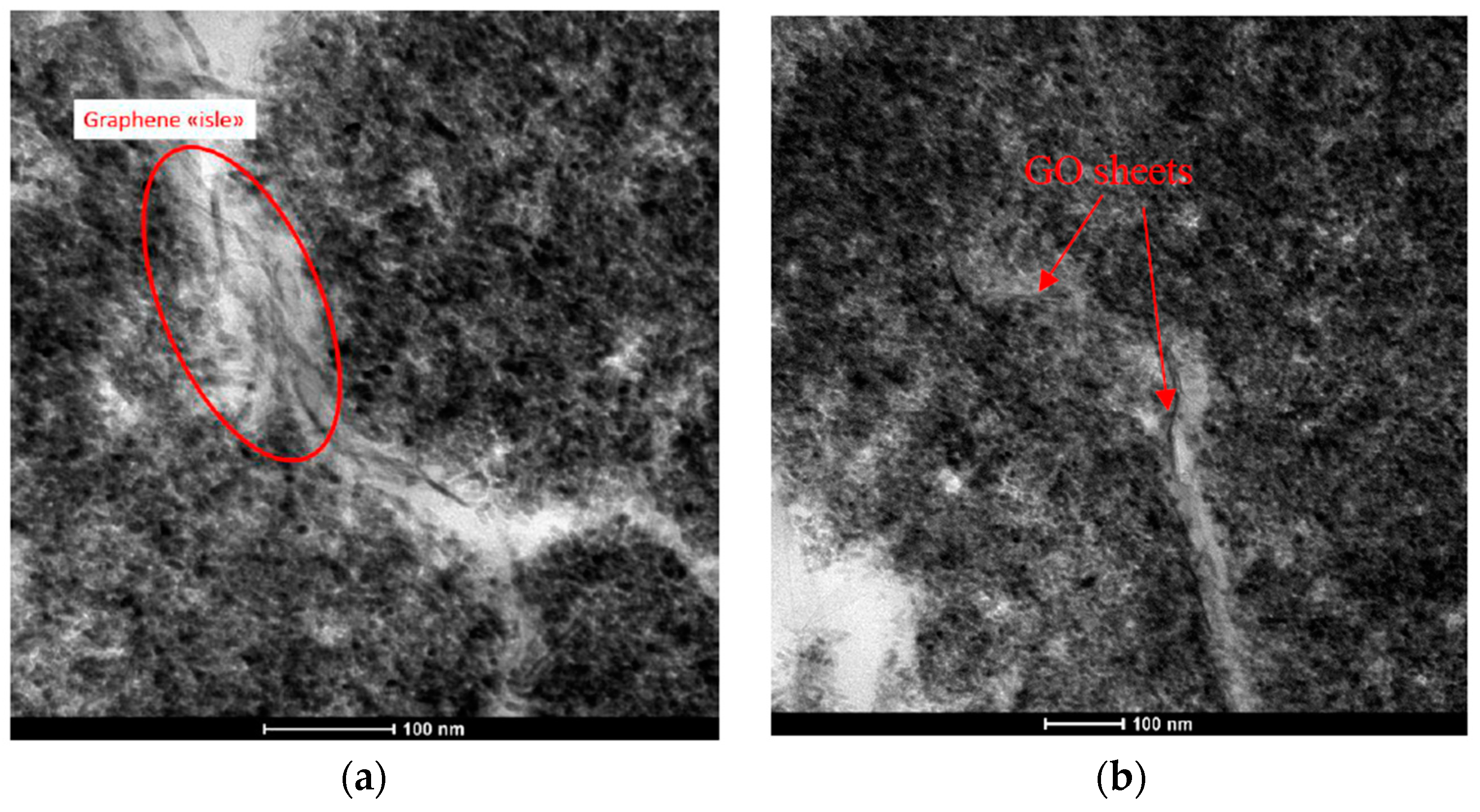
2.1. Materials and Mats Characterization

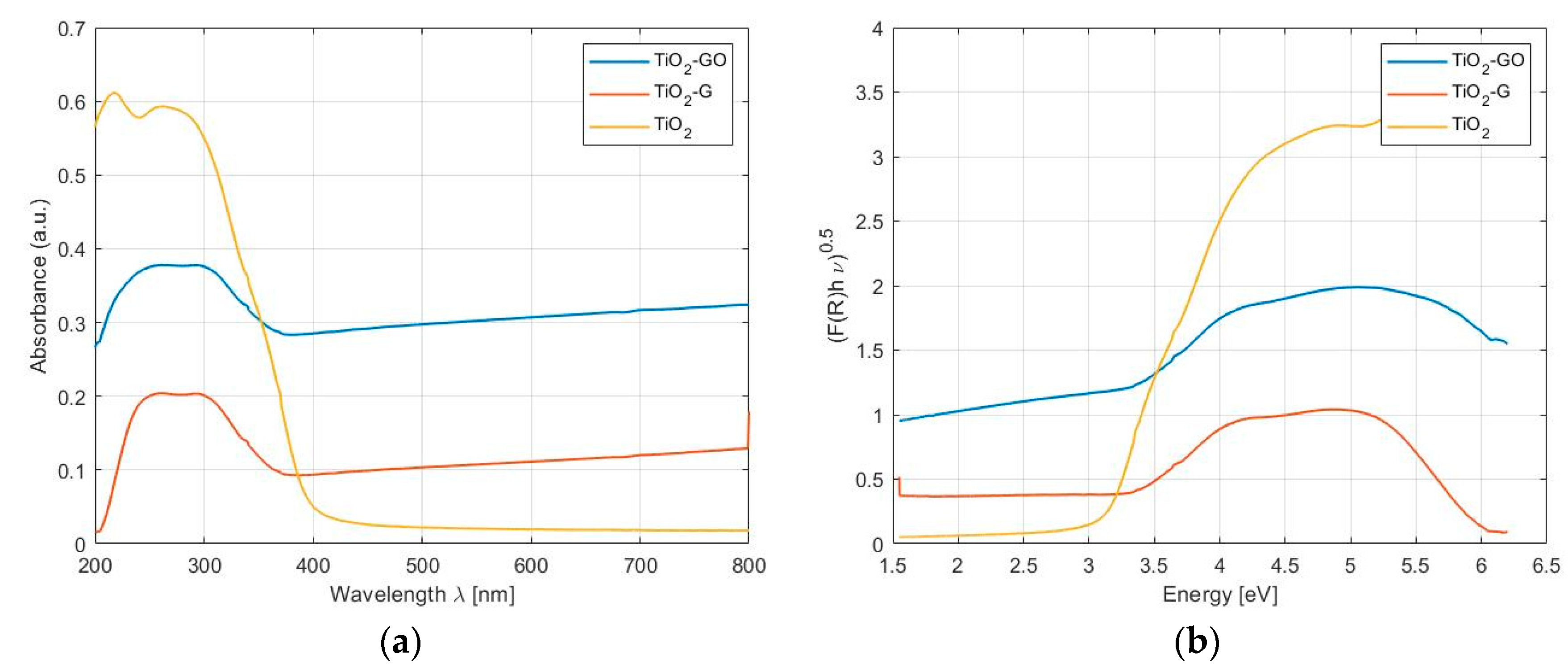
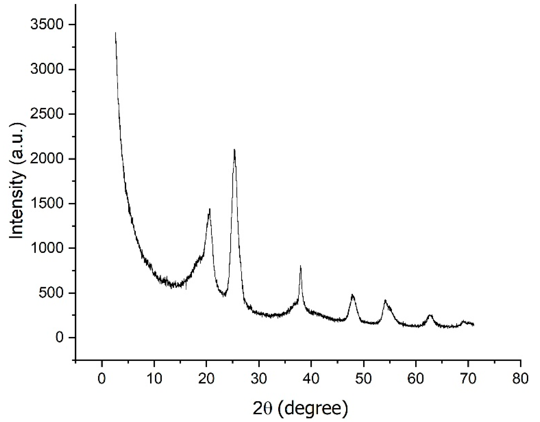
2.1.1. Photo-Catalytic Systems

All the synthesized photo-catalytic systems were properly characterized before production of the nanostructured media.
The chemistry of pristine graphene and graphene oxide had been investigated by FTIR spectroscopy and the results have been previously reported [35]. For completeness the FTIR spectra of graphene (G) and graphene oxide (GO) are reported in Figure S2. Moreover, FTIR spectra of the nanocomposite photo-catalysts are showed in Figure S3. The spectrum of the titanium dioxide nanoparticles obtained by solvothermal synthesis confirmed the presence of the main characteristic peaks at 505 cm−1 and 650 cm−1, related to the O-Ti-O bonding in the tetragonal structure of anatase. The absorption bands centered at 3420 cm−1 and 1634 cm−1 may be assigned, respectively, to the stretching and bending vibration of the OH groups associated with the surface adsorbed water [36,37]. Any other significant variations were observed in the spectra of both TiO2-G and TiO2-GO. It was very difficult to distinguish uniquely the graphene based materials, especially because the absorption peak occurring at ca. 1630 cm−1 can be attributed to the skeletal vibration of both the graphene sheets and the water absorbed on the surface of TiO2. It can be supposed that a potential distinctive feature of the graphene based nanocomposites is the shifting of the main peak centered at 650 cm−1 toward lower region in the spectrum. It is indeed possible to observe it in the case of GO; this difference could be related to the presence of both Ti-O-Ti and Ti-O-C bonds in the composites, which means a chemical interaction between surface hydroxyl groups of TiO2 and functional groups of graphene oxide [38].
TEM analysis was performed in order to evaluate the morphology of those systems: micrographs of the two coupled systems TiO2-G and TiO2-GO are reported in Figure 1. In the case of TiO2-G graphene (Figure 1a), it was highlighted the presence of “isles” wherein the graphene sheets were predominantly confined, within the TiO2 particles. On the contrary, in the case of GO, it resulted better dispersed within the catalyst (Figure 1b).
Band gap and absorption limits were measured (Figure 2) and their values are reported in Table 1. According to the literature [39] all the graphene based composites showed a strong shift of the absorption edge respect to titanium dioxide and narrowed band gap, probably due to the modification that graphene oxide induces on the optical properties of TiO2 because of their interaction.
WAXD diffractograms collected for the pristine TiO2, obtained by solvothermal method, showed the presence of the only crystallographic phase of anatase with the peaks located at 25.3°, 37.8°, 48°, 54.1°, 55°, 62.8°, 68.9° and 70.3°, which can be indexed to the (101), (004), (200), (105), (211), (204), (116) and (220) crystal planes of anatase (JCPDS card n 71–166) (Figure 3). Due to the low content of graphene and graphene oxide (ratio TiO2:G or GO was 10:1), the single peak at 9.28°, which represents the typical diffraction peak of the basal plane of the layers which constitute the material, couldn’t be distinguished. However, a further well-resolved diffraction peak at 2θ = 21.5° was observed in the pattern, which can be indexed to the (0 0 2) plane of reduced graphene oxide (rGO) [40]. This result suggests that GO undergoes partial reduction during hydrothermal treatment.
From WAXD data, the average size of crystallites was determined to be 6.91 nm by using the Scherrer equation.

2.1.2. Nonwoven Mats Characterization

Regarding the active media, SEM analysis was not effective to distinguish any specific feature of the three different systems, because of the implemented approach used for the preparation of the nanostructured membranes, that is the so-called two-step approach. It is in fact a procedure that provides for the deposition of a layer of nanofibers followed by the deposition of nanoparticles via electro-spraying over the nonwoven. Some micrographs of the nanostructured membranes are reported in Figure S4. According to our previous studies [32,33,34,35], the deposition of the TiO2 nanoparticles had the tendency to create clusters when spread over the nanofibers surface resulting in a relative thick layer that cover the fibrous structure. Consequently, in order to evaluate the morphology of the mat we looked at TEM micrographs (Figure 4), wherein all the components were evident: the outer layer of TiO2 nanoparticles, the nanofibers cross section (the spherical shapes within the gray matrix); in order to appreciate the difference among the photocatalytic systems, the reader has to refer to the previous paragraph.
TGA analysis (Figure S4) has provided the data useful both for quantitative analysis and for the evaluation of the distribution of the photo-catalyst on the electrospun mats. For practical reasons, the mats were cut in several pieces and they were analysed individually. The obtained results in terms of mg of catalyst per unit of surface are reported in Table 2.
As regards the quality of distribution, a 4% deviation in the final weight residual for different samples was observed with a consequent validation of the electrospraying process as a good candidate for this purpose.
The presence of leaching effects were assessed by performing TGA analysis both before and after mats use. The obtained results showed a negligible variation in the photo-catalyst content. Consequently, it can be asserted d that the catalytic system is stable, especially due to Van der Waals forces, which promote strong adhesion among nanoparticles themselves [32] and to the small amount of polymer, which acts as a binder.

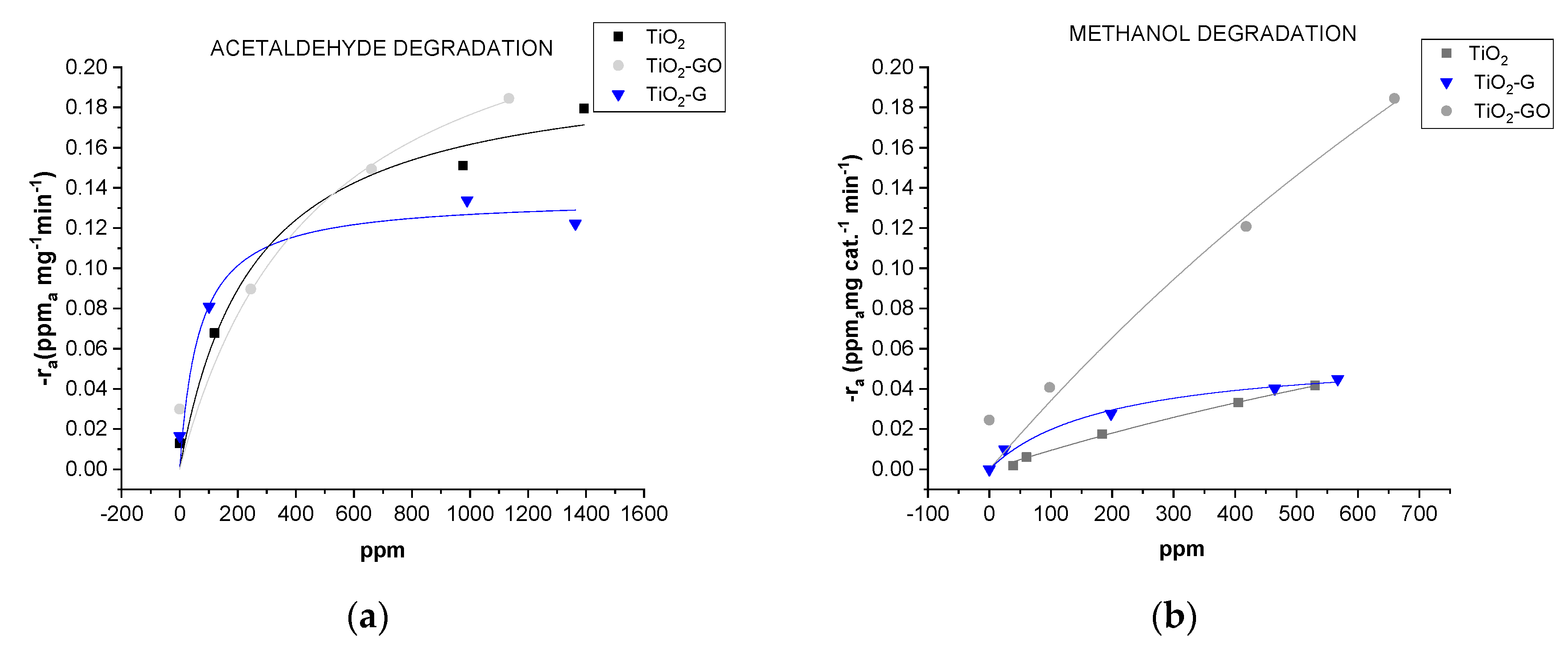
2.2. Photo-Catalytic Performance

The photo-catalytic oxidation of the two gas-phase pollutants (acetaldehyde and methanol, respectively) was monitored according to the same procedure previously used, in order to have a better understanding of the effect of both the crystallographic structure of titanium oxide and the presence of graphene-like promoters within the structure of the semiconductor itself. Blank experiments at the same conditions showed that there was no activity in the absence of photo-catalyst or light irradiation. All the experiments were replicated on three sets of each filter media, for statistical significance and three consecutive cycles of photo-degradation have been run for all the mats, in order to have an idea of their lifetime. Every cycle consists of: an injection of pollutant; a conditioning step; a reaction step and a regenerative step. The photocatalytic activity of the systems TiO2, TiO2-G, and TiO2-GO in terms of acetaldehyde (c0 = 1100 ± 150 ppm) and methanol abatement (530 ± 40 ppm) versus time are reported in Figure 5a,b as well as the related normalized data (Figure 5c,d). Looking at the acetaldehyde degradation, the initial concentration is completed removed by TiO2-G and TiO2-GO in 15 and 20 min, respectively, whereas the system based on neat TiO2 led a complete degradation in 40 min. Further evidence of the better performance of the nanocomposite systems may be depicted from the graph related to the moles reacted per gram of catalyst (Figure 5c), that confirmed this behavior. These results can be ascribed to the aforementioned properties of graphene and in the particular case of GO, its better dispersion within the TiO2, verified by TEM analysis, allowed to both enhance the pollutant adsorption, the common limiting reaction step, and reducing the recombination of electron–hole pairs. Methanol photo-degradation has been found to be enhanced especially by the system based on TiO2-GO, and an additional explanation beyond the morphology, can be attributed to the lower band gap obtained for this system (2.5 eV), with respect to the pristine TiO2 (3.21 eV).
A further evaluation about the efficacy of the mat preparation approach could be done by comparing photo-degradation normalized data obtained for the nanostructured mat with PVDF-TiO2 by one-step approach, wherein the mat is obtained by electrospinning of a polymer-photo-catalyst ink [33] versus the same obtained by two step approach (electrospun fibers plus electrosprayed nanoparticles). Despite our previous studies [35], the amount of moles reacted is both cases are roughly the same, even though it was expected to be higher in the one-step approach because of the high surface area provided by the porous structure of the mats. These results can be ascribed to the composition of TiO2 catalyst obtained by solvothermal method, that, according to the WAXD analysis, was completely based on anatase, the most active crystallographic phase. Also, anatase displays a lower average effective mass of photo-generated electrons and holes. Therefore, the electrons and holes will migrate faster from the bulk to the surface, whit a consequent lower recombination rate [41].
Looking at the experimental data, they are fitted by Langmuir-type kinetic such as r A   =   d C A d t   =   k T K C A 1 + K C A where kT is the limiting rate constant of reaction at maximum coverage under the given experimental conditions and K is the equilibrium constant for adsorption of the substrate onto catalyst. In particular the reaction rate −rA (ppm of pollutant A/mg of catalyst *min) is plotted as a function of the concentration CA (ppm) (Figure 6). The obtained kinetic constants (Table 3) for the system TiO2-GO revealed both higher kT (fourfold for methanol) and K with respect to the neat TiO2. The system TiO2-G showed unexpectedly lower kT, but higher K (one order of magnitude) for both pollutants. Actually, the presence of COO− groups found in graphene oxide, allows for better interaction with Ti(IV) ions through metal-ions complexes, during in-situ TiO2 formation [42,43]. This leads to a better dispersion of graphene sheets within the catalysts, as suggested by TEM micrograph (Figure 1). Furthermore, according to the literature [35,44], we may speculate that during the solvothermal synthesis of the nanocomposite system TiO2-GO there is a partial reduction of the graphene oxide to reduced graphene oxide (rGO) with a consequent intimate interaction with the titanium oxide nanoparticles and consequently an increased photo-degradation efficiency.
The presence of graphene-based promoters has therefore seen a significant increase in the photo-activity of all the nanocomposite catalysts probably due to two main reasons: first, they allow enhancing the pollutant adsorption on the semiconductor surface due to their high surface area. Secondly, their electron mobility is a key factor in the transfer of electrons on the surface with a consequent delay of the recombination reactions between electron-hole pairs. Further radical species may be generated by reaction of electrons with adsorbed O2 to O2 radicals or by interaction of −OH groups on the surface with holes (h+) to generate •OH radicals.

3. Experimental

3.1. Materials

Acetic acid (AcH, assay ≥ 99.5%), 2-Propanol (IPA, assay ≥ 99.5%), titanium isopropoxide (TTiP, assay ≥ 97%) and triethylamine (TEA, assay ≥ 99.5%), obtained by Sigma-Aldrich, St. Luis, MO, USA, were used as reagents for the hydrothermal synthesis of titanium oxide nanoparticles, TiO2. Graphene oxide, GO, (Sigma-Aldrich, St. Luis, MO, USA) and few layer graphene, G, (Avanzare Innovación Tecnológica S.L. (La Rioja, Spain) were employed as photocatalytic promoters of the systems TiO2-GO and TiO2-G.
Polyvinylidenfluoride (PVDF, Kynar® 500, Arkema, Colombes, France) was used in the production of electrospun nanofibers because of its high UV resistance. N,N-dimethylformamide (DMF), and acetone (from Sigma-Aldrich, St. Luis, MO, USA) were the solvents used after dehydration by storage over molecular sieves.

3.2. Catalytic Systems and Nonwowen Mats Production

The catalytic systems were obtained by solvothermal method and are summarized as follows:
  • Titanium dioxide (TiO2)
  • TiO2-Graphene (TiO2-G)
  • TiO2-Graphene oxide (TiO2-GO)
The preparation procedure of the photo-catalysts has been the following:
TiO2, TiO2-Graphene oxide and TiO2-Graphene nano-powders were prepared by solvothermal synthesis, following an approach defined to obtain nanostructured TiO2-based materials [45,46,47]. In the first step, a typical precursor solution was obtained by adding dropwise 6 mL of TTiP/IPA solution (Sol-1, 3.38 M in TTiP) to 31.3 mL of water solution at pH 1.5 achieved by means of AcH (Sol-2). After Sol-1 addition, a white precipitate was achieved. The formation of a yellowish colloidal solution after two days stirring at room temperature, indicated resuspension of the precipitate and reduction in particles size below 20 nm [48]. Subsequently, TEA was added dropwise to the TiO2 colloidal solution up to pH = 7. The obtained yellow-white precipitate suspension was sealed within a Teflon container (the liquid volume corresponding to 75% of the whole), placed into a circulating oven at 120 °C for 24 h. TiO2 nanoparticles were then separated by centrifugation and repeated washing (3 times with distilled water). The obtained precipitates were dried at 90 °C.
Graphene oxide-TiO2 and Graphene-TiO2 were prepared in situ by following almost the same procedure as bare TiO2. Briefly, Sol-1 (6 mL) was added drop-wise to Sol-2 (31.3 mL) and the mixture was kept stirred for two days leading to TiO2 colloidal solution. Then, an appropriate amount (50 mg) of graphene oxide (GO) and graphene (G) for 1.193 mL of TTiP were alternately added in order to obtain the final hybrid nanosystems. Then, the two mixtures were separately neutralized with TEA until pH 7. Finally, the obtained suspensions were sealed within a Teflon recipient (the liquid phase consisting of 75% of the whole volume), placed into a circulating oven and kept at 120 °C for 24 h. In both cases, the obtained hybrid precipitates were centrifuged and washed repeatedly with distilled water and finally dried at 90 °C. These photocatalytic systems have been sprayed onto an electrospun PVDF mat. A 15%w/w solution of PVFD in DMF/Acetone (2:1) was electrospun at 1.2 kV/cm, 2 mL/h, with a 70% RH and a temperature of 20 °C, needle 22 G for 1 h. Subsequently, a 5%w/w suspension of the produced catalyst properly dispersed in ethanol by sonication, was electro sprayed at 1.25 kV/cm, 8 mL/h, 30–40% of RH, and a temperature of 20 °C, needle 22 G to get the final active media.

3.3. Methods

Morphological analysis was performed by scanning electron microscopy, SEM, (JSM-6490, JEOL Ltd. Tokyo, Japan) and transmission electron microscopy, TEM, (Tecnai G2, FEI Company, Hillsboro, OR, USA) with digital camera (Veleta, Olympus Soft Imaging System, Muenster, Germany). For the latter, ultrathin sections (90–100 nm) of samples embedded in LR White acrylic resin were obtained with an Ultrotome V (LKB-Produkter AB, Bromma, Sweden) ultramicrotome.
FTIR spectra of all the obtained photo-catalytic systems were collected with an infrared spectrometer (Nicolet iS50, Thermo Fisher Scientific, Waltham, MA, USA) in transmission mode, using KBr tablets, in the 4000–400 cm−1 wavenumber range (64 scans, 4 cm−1 resolution). A background spectrum was run before each analysis and samples spectra were normalized against it.
Diffuse reflectance UV-visible spectroscopy (DRS) was employed in order to get information about the band gap and the absorption limit of the produced photo-catalytic systems. A UV-visible-NIR spectrophotometer (Cary 5000, Agilent Technologies, Santa Clara, CA, USA) with an integrating sphere attachment was used for this purpose, in the range of 200–800 nm. BaSO4 was used as the reflectance standard material.
The evaluation of crystallographic structures was obtained by Wide Angle X-ray diffraction (WAXD) patterns that were recorded in a 2θ angular range of 1.5° to 70° on a Philips X’Pert PRO diffractometer (Malvern Panalytical, Malvern, UK), working in reflection geometry and equipped with a graphite monochromator on the diffracted beam (CuKα radiation). The scanning step size was 0.02° with a measured uncertainty in terms of d-spacing of about 0.05 nm (2σ).
The photo-catalyst content and distribution on the electrospun mat were investigated by thermogravimetric analysis (TGA, SDT-Q600 TA Instruments, New Castle, DE, USA) under air flow at a flow rate of 100 mL/min and at a constant heating rate of 20 °C/min from room temperature up to 900 °C.

3.4. Photo-Catalytic Testing Station

The photoreactor is the same used for previous experiments [33]. It consists in a Pyrex tubular reactor (dimensions: 370 mm in length, 100 mm of internal diameter, 2780 cm3 of volume), with the nonwoven membranes placed on an annular scaffold around the UV lamp tube. The testing station configuration (Figure S1) is made up of a primary pump, with a flow rate equal to 30 L/min that provides the continuous recirculation of dry air with the VOC in the reactor. Different flow rates of the primary pump have been tested in order to assess that that the flux of the primary pump does not affect the VOC removal. A volumetric pump set with a proper gas syringe carried out the VOC injection. After injection and conditioning, the UV lamp was switched on and the temperature reached in the photo-reactor was found to be 50 °C. The initial concentration of pollutant is recorded in this step, that is 530 ± 40 ppm for methanol and 1100 ± 150 ppm for acetaldehyde. The pollutant concentration was regularly monitored over time, until complete degradation was reached. Then, the UV lamp was turned off and the reactor was flushed with dried air for 1 h. Subsequently, two more experiments were run for each mat type and pollutant.
Some preliminary tests were run in order to determine if any other factor, different from the catalytic system, could degrade the pollutant under analysis. The procedure was previously reported [33] and it consist of tests run with membrane in dark conditions, tests with UV light but without membrane and tests with UV light and the metallic grid support (no nanostructured mat). These tests confirmed that without functionalized membrane there was no significant variation in the pollutants concentration within the reactor.
As regards the sampling procedure, the sampled VOCs were injected through a six-port external injection GC valve (6890 Valco Instrument Co., Inc. Houston, TX, USA) troughtout a 100 μL sample loop. The samples were then analysed by a Gas Chromatograph Trace 1300® coupled with the Single Quadrupole Mass Spectrometer ISQQD®, (Thermo Scientific, Waltham, MA, USA) whit pure helium as a carrier gas and with a capillary column MEGA (0.32 mm i.d., 30 m length and 5 μm film thickness). Furthermore, the mean irradiance and photon flux were calculated to be 1.35 W/m2 and 3.03 × 10⁶ moles/(m2s), respectively [35].

4. Conclusions

This work investigated the photocatalytic performance towards VOC abatement of electrospun active mats. Notably, graphene-based photocatalytic promoters were combined to TiO2 nanostructures, during their formation through in-situ solvothermal process. Produced photo-catalytic graphene-TiO2 systemswere subsequently electro sprayed over nanofibrous supports. Obtained active mats were properly tested for gas-phase abatement of acetaldehyde and methanol in gas-phase, consecutively.
As highlighted by electron microscopy, graphene tends to be confined within “isle” among TiO2 nanoparticles, while graphene oxide is more uniformly dispersed within the TiO2 matrix. The band gap and the absorption limit evaluation showed that all the proposed systems have a lower band gap than neat TiO2 and the absorption limit is shifted from 388 nm up to 603 nm.
Looking at the photocatalytic activity, the number of reacted moles per gram of catalyst was significantly higher for the system based on graphene oxide TiO2-GO even though a complete degradation of the pollutants has been achieved also in presence of TiO2-G. On the other hand the kinetic analysis revealed the system TiO2-GO had higher kinetic constants with respect both the pollutants. This behavior may be related to better dispersion of GO within the nanostructures as well as to the partial reduction of GO to rGO during solvothermal synthesis, with a consequent increased photodegradation efficiency due to a greater charge separation over the catalyst surface.

Supplementary Materials

The following are available online at https://www.mdpi.com/2073-4344/10/9/1017/s1, Figure S1: Photocatalytic testing station, Figure S2: FTIR spectra of Graphene and GrapheneOxide, Figure S3: FTIR spectra of nanocomposite photocatalysts, Figure S4: SEM micrograph of nanostructured mat based on PVDF-TiO2. Detail at higher magnification (bar scale 1 μm), Figure S5: TGA Thermograms of electrospun mats: (a) PVDF-TiO2; (b) PVDF-TiO2-G; (c) PVDF-TiO2-GO.

Author Contributions

Conceptualization, M.R., M.M. and A.L.; Data curation, C.B. and G.V.; Investigation, C.B. and G.V.; Methodology, M.R., G.L., G.V; Project administration, M.R.; Supervision, M.M.; Visualization, G.L., A.L.; Writing—original draft C.B. and M.R.; Writing—review and editing, M.R., G.V., G.L, M.M. and A.L. All authors have read and agreed to the published version of the manuscript.

Funding

This research received no external funding.

Conflicts of Interest

The authors declare no conflict of interest.

References

  1. Parmar, G.R.; Rao, N.N. Emerging control technologies for volatile organic compounds. Crit. Rev. Environ. Sci. Technol. 2009, 39, 41–78. [Google Scholar] [CrossRef]
  2. Mozaffara, A.; Zhang, Y.L.; Fan, M.; Cao, F.; Lin, Y.C. Characteristics of summertime ambient VOCs and their contributions to O3 and SOA formation in a suburban area of Nanjing, China. Atmos. Res. 2020, 240, 104923. [Google Scholar] [CrossRef]
  3. Mamaghani, A.H.; Haghighat, F.; Lee, C.-S. Photocatalytic oxidation technology for indoor environment air purification: The state-of-the-art. Appl. Catal. B Environ. 2017, 203, 247–269. [Google Scholar] [CrossRef]
  4. Zhao, J.; Yang, X.D. Photocatalytic oxidation for indoor air purification: A literature review. Build. Environ. 2003, 38, 645–654. [Google Scholar] [CrossRef]
  5. Weon, S.; He, F.; Choi, W. Status and challenges in photocatalytic nanotechnology for cleaning air polluted with volatile organic compounds: Visible light utilization and catalyst deactivation. Environ. Sci. Nano 2019, 6, 3185–3214. [Google Scholar] [CrossRef]
  6. Wang, Z.; Huang, Y.; Ho, W.; Cao, J.; Shen, Z.; Lee, S.C. Fabrication of Bi2O2CO3/g-C3N4 heterojunctions for efficiently photocatalytic NO in air removal: In-situ self-sacrificial synthesis, characterizations and mechanistic study. Appl. Catal. B Environ. 2016, 199, 123–133. [Google Scholar] [CrossRef] [Green Version]
  7. Chen, D.; Zhang, H.; Liu, Y.; Li, J. Graphene and its derivatives for the development of solar cells, photoelectrochemical, and photocatalytic applications. Energy Environ. Sci. 2013, 6, 1362–1387. [Google Scholar] [CrossRef]
  8. Wang, G.; Ling, Y.C.; Li, Y. Oxygen-deficient metal oxide nanostructures for photoelectrochemical water oxidation and other applications. Nanoscale 2012, 4, 6682–6691. [Google Scholar] [CrossRef]
  9. Murdoch, M.; Waterhouse, G.I.N.; Nadeem, M.A.; Metson, J.B.; Keane, M.A.; Howe, R.F.; Llorca, J.; Idriss, H. The Effect of Gold Loading and Particle Size on Photocatalytic Hydrogen Production from Ethanol over Au/TiO2 Nanoparticles. Nat. Chem. 2011, 3, 489–492. [Google Scholar] [CrossRef]
  10. Weber, A.S.; Grady, A.M.; Koodali, R.T. Lanthanide modified semiconductor photo-catalysts. Catal. Sci. Technol. 2012, 2, 683–693. [Google Scholar] [CrossRef]
  11. Gurunathan, K. Photocatalytic hydrogen production using transition metal ions-doped γ-Bi2O3 semiconductor particles. Int. J. Hydrogen Energ. 2004, 29, 933–940. [Google Scholar] [CrossRef]
  12. Clarizia, L.; Vitiello, G.; Pallotti, D.K.; Silvestri, B.; Nadagouda, M.; Lettieri, S.; Luciani, G.; Andreozzi, R.; Maddalena, P.; Marotta, R. Effect of surface properties of copper-modified commercial titanium dioxide photocatalysts on hydrogen production through photoreforming of alcohols. Int. J Hydrogen Energ. 2017, 42, 28349–28362. [Google Scholar] [CrossRef]
  13. Vitiello, G.; Clarizia, L.; Abdelraheem, W.; Esposito, S.; Bonelli, B.; Ditaranto, N.; Vergara, A.; Nadagouda, M.; Dionysiou, D.D.; Andreozzi, R.; et al. Near UV-Irradiation of CuOx-Impregnated TiO2 providing active species for H2 production through methanol photoreforming. ChemCatChem 2019, 11, 4314–4326. [Google Scholar] [CrossRef]
  14. Hou, Y.D.; Wang, X.C.; Wu, L.; Chen, X.F.; Ding, Z.X.; Wang, X.X.; Fu, X.Z. N-Doped SiO2/TiO2 mesoporous nanoparticles with enhanced photocatalytic activity under visible-light irradiation. Chemosphere 2008, 72, 414–421. [Google Scholar] [CrossRef]
  15. Liu, G.; Niu, P.; Sun, C.H.; Smith, S.C.; Chen, Z.G.; Lu, G.Q.; Cheng, H.M. Unique Electronic Structure Induced High Photoreactivity of Sulfur-Doped Graphitic C3N4. J. Am. Chem. Soc. 2010, 132, 11642–11648. [Google Scholar] [CrossRef] [PubMed]
  16. Chen, D.; Zhang, H.; Hu, S.; Li, J.H. Preparation and Enhanced Photoelectrochemical Performance of Coupled Bicomponent ZnO−TiO2 Nanocomposites. J. Phys. Chem. C 2008, 112, 117–122. [Google Scholar] [CrossRef]
  17. Chen, X.F.; Wang, X.C.; Fu, X.Z. Hierarchical macro/mesoporous TiO2/SiO2 and TiO2/ZrO2 nanocomposites for environmental photocatalysis. Energy Environ. Sci. 2009, 2, 872–877. [Google Scholar] [CrossRef]
  18. Dal Lago, E.; Boaretti, C.; Piovesan, F.; Roso, M.; Lorenzetti, A.; Modesti, M. The effect of different compatibilizers on the properties of a post-industrial PC/PET blend. Materials 2018, 12, 49. [Google Scholar] [CrossRef] [Green Version]
  19. Zhang, L.L.; Zhang, H.C.; Huang, H.; Liu, Y.; Kang, Z.H. Ag3PO4/SnO2 semiconductor nanocomposites with enhanced photocatalytic activity and stability. New J. Chem. 2012, 36, 1541–1544. [Google Scholar] [CrossRef]
  20. Sharma, S.K.; Sokhi, S.; Balomajumder, C.; Satapathi, S. Reusable graphene oxide nanofibers for enhanced photocatalytic activity: A detailed mechanistic study. J. Mater Sci. 2017, 52, 5390–5403. [Google Scholar] [CrossRef]
  21. Fu, D.; Zhang, L.; Xie, R.; Xu, H.; Zhong, Y.; Sui, X.; Mao, Z. Fabrication of novel rGO/Bi20TiO32 heterojunction for enhanced visible-light photocatalytic activity. J. Photochem. Photobiol. A 2016, 329, 18–25. [Google Scholar] [CrossRef]
  22. Maira, A.J.; Coronado, J.M.; Augugliaro, V.; Yeung, K.L.; Conesa, J.C.; Soria, J. Fourier Transform infrared study of the performance of nanostructured TiO2 particles for the photocatalytic oxidation of gaseous toluene. J. Catal. 2001, 202, 413–420. [Google Scholar] [CrossRef] [Green Version]
  23. Lin, W.; Xie, X.; Wang, X.; Wang, Y.; Segets, D.; Sun, J. Efficient adsorption and sustainable degradation of gaseous acetaldehyde and o-xylene using rGO-TiO2 photo-catalyst. Chem. Eng. J. 2018, 349, 708–718. [Google Scholar] [CrossRef]
  24. Muñoz-Batista, M.J.; Ballari, M.M.; Cassano, A.E.; Alfano, O.M.; Kubacka, A.; Fernández-García, M. Ceria promotion of acetaldehyde photo-oxidation in a TiO2-based catalyst: A spectroscopic and kinetic study. Catal. Sci. Technol. 2015, 5, 1521. [Google Scholar] [CrossRef]
  25. Verbruggen, S.W.; Masschaele, K.; Moortgat, E. Factors driving the activity of commercial titanium dioxide powder towards gas phase photocatalytic oxidation of acetaldehyde. Catal. Sci. Technol. 2012, 2, 2311–2318. [Google Scholar] [CrossRef]
  26. Danon, A.; Bhattacharyya, K.; Vijayan, B.K. The effect of reactor materials on the properties of titanium oxide nanotubes. ACS Catal. 2012, 2, 45–49. [Google Scholar] [CrossRef]
  27. Bianchi, C.L.; Gatto, S.; Pirola, C.; Naldoni, A.; Di Michele, A.; Cerrato, G.; Crocellà, V.; Capucci, V. Photocatalytic degradation of acetone, acetaldehyde and toluene in gas-phase: Comparison between nano and micro-sized TiO2. Appl. Catal. B Environ. 2014, 146, 123–130. [Google Scholar] [CrossRef]
  28. Wahab, R.; Tripathy, S.K.; Shin, H.-S.; Mohapatra, M.; Musarrat, J.; Al-Khedhairy, A.A.; Kumar Kaushik, N. Photocatalytic oxidation of acetaldehyde with ZnO-quantum dots. Chem. Eng. J. 2013, 226, 154–160. [Google Scholar] [CrossRef]
  29. Vijayan, B.K.; Dimitrijevic, N.M.; Finkelstein-Shapiro, D. Coupling titania nanotubes and carbon nanotubes to create photocatalytic nanocomposites. ACS Catal. 2012, 2, 223–229. [Google Scholar] [CrossRef]
  30. Hamal, D.B.; Klabunde, K.J. Valence state and catalytic role of cobalt ions in cobalt TiO2 nanoparticle photo-catalysts for acetaldehyde degradation under visible light. J. Phys. Chem. C 2011, 115, 17359–17367. [Google Scholar] [CrossRef]
  31. Huang, X.; Yuan, J.; Shi, J.W. Ozone-assisted photocatalytic oxidation of gaseous acetaldehyde on TiO2/H-ZSM-5 catalysts. J. Hazard Mater. 2009, 171, 827–832. [Google Scholar] [CrossRef] [PubMed]
  32. Modesti, M.; Roso, M.; Boaretti, C.; Besco, S.; Hrelja, D.; Sgarbossa, P.; Lorenzetti, A. Preparation of smart nano-engineered electrospun membranes formethanol gas-phase photoxidation. Appl. Catal. B Environ. 2014, 144, 216–222. [Google Scholar] [CrossRef]
  33. Roso, M.; Lorenzetti, A.; Boaretti, C.; Hrelja, D.; Modesti, M. Graphene/TiO2 based photo-catalysts on nanostructured membranes as a potential active filter media for methanol gas-phase degradation. Appl. Catal. B Environ. 2015, 176, 225–232. [Google Scholar] [CrossRef]
  34. Roso, M.; Boaretti, C.; Pelizzo, M.G.; Lauria, A.; Modesti, M.; Lorenzetti, A. Nanostructured photo-catalysts based on different oxidized graphenes for VOCs removal. Ind. Eng. Chem. Res. 2017, 56, 9980–9992. [Google Scholar] [CrossRef]
  35. Roso, M.; Boaretti, C.; Bonora, R.; Modesti, M.; Lorenzetti, A. Nanostructured active media for VOCs abatement: The synergy of graphene oxide and semiconductors coupling. Ind. Eng. Chem. Res. 2018, 57, 16635–16644. [Google Scholar] [CrossRef]
  36. Pant, H.R.; Park, C.H.; Pokharel, P.; Tijing, L.D.; Lee, D.S.; Kim, C.S. ZnO micro-flowers assembled on reduced graphene sheets with high photocatalytic activity for removal of pollutants. Powder Technol. 2013, 235, 853–858. [Google Scholar] [CrossRef]
  37. Yu, J.C.; Zhang, L.; Zheng, Z.; Zhao, J. Synthesis and Characterization of Phosphated Mesoporous Titanium Dioxide with High Photocatalytic Activity. Chem. Mater. 2003, 15, 2280–2286. [Google Scholar] [CrossRef]
  38. Williams, G.; Seger, B.; Kamat, P.V. TiO2-Graphene Nanocomposites. UV-Assisted Photocatalytic Reduction of Graphene Oxide. ACS Nano 2008, 2, 1487–1491. [Google Scholar] [CrossRef]
  39. Nguyen-Phan, T.; Pham, V.H.; Shin, E.W.; Pham, H.S.; Chung, K.J.S.; Kim, E.J.; Hur, S.H. The role of graphene oxide content on the adsorption-enhanced photocatalysis of titanium dioxide/graphene oxide composites. Chem. Eng. J. 2011, 170, 226–232. [Google Scholar] [CrossRef]
  40. Gupta, B.; Kumar, N.; Panda, K.; Kanan, V.; Joshi, S.; Visoly-Fisher, I. Role of oxygen functional groups in reduced graphene oxide for lubrication. Sci. Rep. 2017, 7, 45030. [Google Scholar] [CrossRef]
  41. Zhang, J.; Zhou, P.; Liu, J.; Yu, J. New understanding of the difference of photocatalytic activity among anatase, rutile and brookite TiO2. Phys. Chem. Chem. Phys. 2014, 16, 20382–20386. [Google Scholar] [CrossRef] [PubMed]
  42. López-Díaz, D.; López Holgado, M.; García-Fierro, J.L.; Velázquez, M.M. Evolution of the Raman Spectrum with the Chemical Composition of Graphene Oxide. J. Phys. Chem. C 2017, 121, 20489–20497. [Google Scholar] [CrossRef]
  43. Vitiello, G.; Pezzella, A.; Calcagno, V.; Silvestri, B.; Raiola, L.; D’Errico, G.; Costantini, A.; Branda, F.; Luciani, G. 5,6-Dihydroxyindole-2-carboxylic Acid–TiO2 Charge Transfer Complexes in the Radical Polymerization of Melanogenic Precursor(s). J. Phys. Chem. C 2016, 120, 6262–6268. [Google Scholar] [CrossRef]
  44. Tayebi, M.; Kolaei, M.; Tayyebi, A.; Masoumi, Z.; Belbasi, Z.; Lee, B.K. Reduced graphene oxide (RGO) on TiO2 for an improved photoelectrochemical (PEC) and photocatalytic activity. Sol. Energy 2019, 190, 185–194. [Google Scholar] [CrossRef]
  45. Jiang, B.; Yin, H.; Jiang, T.; Jiang, Y.; Feng, H.; Chen, K.; Zhou, W.; Wada, Y. Hydrothermal synthesis of rutile TiO2 nanoparticles using hydroxyl and carboxyl group-containing organics as modifiers. Mater. Chem. Phys. 2006, 98, 231–235. [Google Scholar] [CrossRef]
  46. Vitiello, G.; Pezzella, A.; Zanfardino, A.; Varcamonti, M.; Silvestri, B.; Costantini, A.; Branda, F.; Luciani, G. Titania as a driving agent for DHICA polymerization: A novel strategy for the design of bioinspired antimicrobial nanomaterials. J. Mater. Chem. B 2015, 3, 2808–2815. [Google Scholar] [CrossRef]
  47. Vitiello, G.; Pezzella, A.; Zanfardino, A.; Silvestri, B.; Giudicianni, P.; Costantini, A.; Varcamonti, M.; Branda, F.; Luciani, G. Antimicrobial activity of eumelanin-based hybrids: The role of TiO2 in modulating the structure and biological performance. Mater. Sci. Engin. 2017, 75, 454–462. [Google Scholar] [CrossRef]
  48. Oskam, G.; Nellore, A.; Penn, R.L.; Searson, P.C. The Growth Kinetics of TiO2 Nanoparticles from Titanium (IV) Alkoxide at High Water/Titanium Ratio. J. Phys. Chem. B 2003, 107, 1734–1738. [Google Scholar] [CrossRef]
Figure 1. TEM micrographs of TiO2-G (a) and TiO2-GO (b) nanocomposite systems (bar scale 100 nm).
Catalysts 10 01017 g001
Figure 2. UV-visible spectrum of photo-catalysts: (a) DRS spectra of all the synthesized samples for the determination of the absorbance edge and (b) plot of (F(R)hν)0.5 versus the energy for the determination of the band gap of the semiconductors.
Catalysts 10 01017 g002
Figure 3. WAXD diffractograms of the TiO2 obtained by solvothermal method. The same spectra were obtained for the nanocomposite systems (not shown here, for the sake of brevity).
Catalysts 10 01017 g003
Figure 4. TEM image of the PVDF-TiO2GOmat. (bar scale 500 nm).
Catalysts 10 01017 g004
Figure 5. Acetaldehyde removal versus time (a) and normalized data on catalyst mass (c); Methanol removal versus time (b) and normalized data on catalyst mass (d).
Catalysts 10 01017 g005
Figure 6. Reaction rate vs. concentration for acetaldehyde abatement (a) and for methanol abatement (b).
Catalysts 10 01017 g006
Table 1. Band gap energies and absorption edge calculated from DRS spectra for the photo-catalysts and photocatalytic promoters employed.
Photocatalytic SystemAbsorption Limit [nm]Band Gap [eV]
TiO23883.21
TiO2-G4202.9
TiO2-GO6082.25
Table 2. Amount of photo-catalyst on the nonwoven mats from TGA analysis.
Mat TypeSpecific Amount of Photo-Catalyst∙(103) [mg/cm2]
PVDF TiO20.41 ± 0.01
PVDF TiO2-G0.85 ± 0.01
PVDF TiO2-GO0.82 ± 0.01
Table 3. Kinetic constant obtained by fitting data with the equation r A   =   d C A d t   =   k T K C A 1 + K C A .
-Acetaldheyde DegradationMethanol Degradation
Mat TypekT [mg cat−1 min−1]KAdj-R2kT [mg cat−1 min−1]KAdj-R2
PVDF/TiO20.20 ± 0.023.90 × 10−30.97130.198 ± 0.085.00 × 10−40.9983
PVDF/TiO2-GO0.26 ± 0.022.10 × 10−30.91400.813 ± 0.084.38 × 10−40.9380
PVDF/TiO2-G0.14 ± 0.011.49 × 10−20.93370.059 ± 0.0065.11 × 10−30.9848

