1. Introduction
Heterogeneous photocatalysis is considered to be one of the most prospective technologies for wastewater and air pollution treatments. It exhibits high efficiency in the degradation of organic and inorganic contaminants, as well as disinfection of pathogenic microorganisms [
1,
2]. The photocatalysis mechanisms rely on the response of semiconductor materials (TiO
2, ZnO, SnO
2, CeO
2, etc.), which are excited by high-energy photons. The generated electrons are transferred to the conduction band and produce electron-hole pairs that are able to react in distinct media and attack contaminant species.
Despite the research on photocatalysis growing substantially in recent decades, its practical treatment still faces technical challenges [
3]. Conventionally, photocatalyst powders are suspended in liquid media, which implies further post-recovery steps to reuse the material for several times. Although this methodology is favorable from the point of view of the mass transport of reactants and degradation products, the immobilized photocatalysts are often desirable for environmental remediation and clean-up applications. As an alternative to particle dispersion systems, the deposition of a thin layer on a suitable substrate can be easily incorporated into continuous flow systems [
4,
5]. In this context, the use of photocatalytic membrane reactors (PMRs) is considered an effective and mature methodology for photocatalysts’ immobilization and their continuous reuse. Among the different configurations for these devices, the photocatalysts coated onto membranes are found. In some of these cases, the photocatalyst is immobilized over a glass substrate, and then it is joined to a membrane module for the separation of the photocatalytic oxidation products. However, in others, the photocatalyst is directly fixed on a support membrane, which acts as a selective barrier for the contaminants and conducive to the separation of photocatalyst from the medium.
Recent works [
6,
7,
8,
9] have summarized the most relevant achievements regarding the syntheses of materials with excellent photochemical features, as well as the preparation of photocatalytic membranes. Several authors have focused their efforts on the photoactivity improvement impacting the physical properties of photocatalysts (particle size, crystalline phase, preferred orientation) by controlling the synthesis parameters, by doping the semiconductor with a co-catalyst [
10,
11,
12,
13] or even by combining the photocatalyst with other materials [
14,
15,
16]. On the other hand, different ways of manufacturing membranes with a catalyst layer on the surface have also been studied, including techniques such as dip-coating, electrospraying, magnetron sputtering, deposition of gas phase photocatalyst nanoparticles and so on [
4,
17]. Nevertheless, it is noteworthy that the immobilization processes effect the photocatalyst distribution, its stability and accessibility to light-source. Therefore, rigorous analyses and methodologies need to be established to define their final impact on the overall photocatalytic response. Many attempts to improve the performance of the immobilized photocatalyst aim to enhance reactant-catalyst contact through the design of complex structures with large surface-to-volume ratios. Various templating-based routes, including evaporation-induced self-assembly (EISA) [
18,
19] or the evaporation-induced micelles packing (EIMP) [
20], offer a high degree of control over the porosity. However, they are surfactant-assisted sol–gel techniques that require complex procedures with numerous steps. In addition, they should overcome the poor quantity of active material and the limited reactive surface area resulting from a small thickness and/or the low dimension of the substrate or piece [
21].
Nanocellulose compounds extracted from natural resources have also been proposed in literature as promising biotemplates for the generation of porosity in inorganic materials for different applications. Concretely, Korhonen et al. [
22] described the preparation of hollow inorganic nanotubes by coating nanocellulose aerogels with different oxide materials using atomic layer deposition, followed by decomposition of cellulose after calcination. As a demonstration for functionality, they showed that a film made from TiO
2 nanotubes acts as a resistive humidity sensor with relatively rapid response times. Wang et al. [
23] also reported a sol–gel biotemplating route with cellulose nanocrystals to design a photocatalyst for improving hydrogen generation. More specifically, in relation to the contaminants’ removal, Zhang et al. [
24] reported the synthesis of Au-TiO
2 nanopeapods by using bacteria cellulose nanofibers as templates in aqueous solution and their application for the photocatalytic degradation of rhodamine B and methylene blue. Gunji et al. [
25] informed about the synthesis and photocatalytic properties of SiO
2/TiO
2 nanofibers using templates of TEMPO-oxidized cellulose nanofibers. Habibi et al. [
26] also studied the synthesis of TiO
2 nanoparticles coated on cellulose nanofibers with different morphologies and the effect of the template and sol–gel parameters. However, in these last studies the synthetized photocatalysts were not immobilized and were directly applied in the form of powder. Ramimoghadam et al. [
27] also investigated the effects of the lignocellulosic residues of rice straw on physic properties of synthesized TiO
2 nanoparticles via soft template. However, they did not analyze any photochemical response as final evidence of the mentioned effect. Only, Ivanova et al. [
28] includes a study in which the biotemplated titania was immobilized. They achieved a faster photodegradation of 4-chlorophenol in aqueous solutions when nanocrystalline cellulose (NCC), obtained from commercial cotton, is used as biotemplate. The rate constant of the photocatalytic degradation varied from 0.17 to 0.46 h
−1 between non-templated and modified samples. However, the preparation process was long and tedious since the cellulose template was introduced into a sol–gel titania-based precursor with further preformed anatase nanoparticles, which were previously obtained by solvothermal synthesis.
Despite the numerous efforts, it is evident that some challenges are still unresolved and need to be overcome to develop competitive processes for future scaling-up technologies. In this sense, it is necessary to put into practice new ideas about the intrinsic nature of an immobilized nanoparticles system.
In this sense, the colloidal approach could be considered a solution to offer better control on the shaping/immobilization process. Colloid systems enable material assembly across the multiple length scales required for achieving specific designs. It is believed that the innovations in colloid design provide numerous possibilities for the fabrication of new constructs that are unobtainable using traditional methods [
29]. Colloids are a category of heterogeneous mixtures in which one dispersed phase is homogeneously distributed throughout another continuous phase for a long duration without sedimentation. The concept called colloidal processing is proposed to manipulate the compounds’ surfaces [
30]; it allows one to remove heterogeneous agglomerates in suspension and optimize the final properties of materials. The mixture handling in liquid media facilitates the homogeneity of phases. The surface attraction/dispersion, hydrodynamic, and thermal forces determine the phase behavior of colloidal systems on the nanoscale. In addition, relevant bulk properties, such as stability and rheology, are also well-defined by these phenomena.
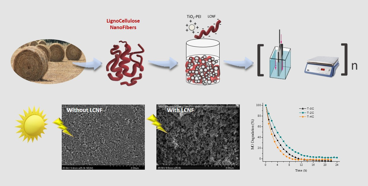
In line with this, we present in this work, a colloidal processing route to immobilize a conventional TiO2-based photocatalyst in which microstructural features are modified by using lignocellulose nanofibers obtained from biomass residues. The composite films are shaped using the dip coating process to achieve full covering substrates that are subsequently thermally treated (at a mild temperature) to remove the biotemplate and consolidate a porous TiO2 microstructure.
2. Results
The solid content of the as-prepared TiO
2 suspension was adjusted in terms of viscosity before evaluating the incorporation of the LCNFs. In the rheological behavior of a colloidal system, the distance between the particles decreases as the solid content increases, causing an increment of the particle–particle interactions, and making the flow difficult. This aspect is very important for both the coating process and the achieved final microstructure since there is a direct relationship between the packaging density of the films and the flow behavior of the photocatalyst suspension. The maximum number of nanoparticles in the liquid media is desirable to achieve the maximum packing density, always keeping an adequate viscosity for our shaping technique. In order to select the optimal solid content of the TiO
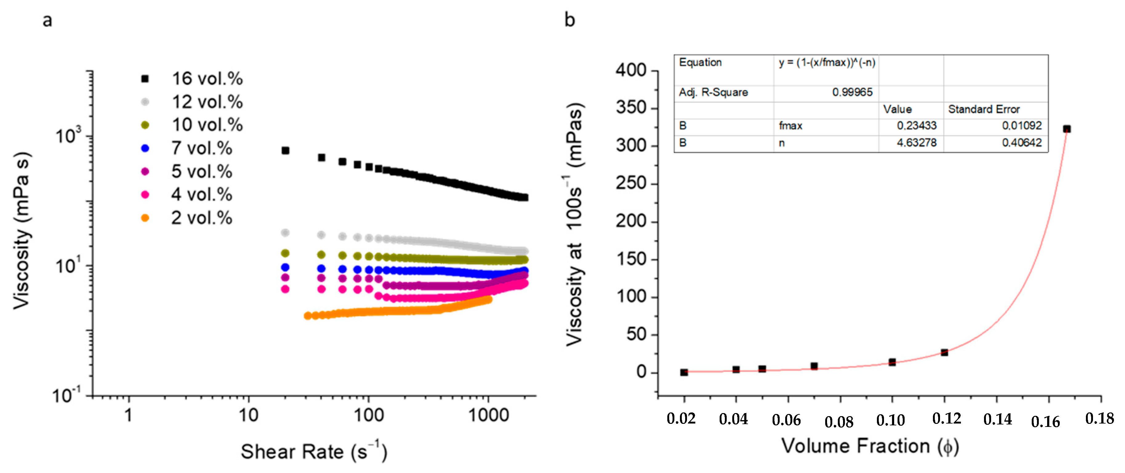
2 suspension and to take the coatings shaped with this formulation as reference, the flow curves were recorded when the solid content increased up to 16 vol.%. All suspensions were prepared with 6 wt.% of PEI as stabilizer and milled for 120 min.
Figure 1a shows the rheograms relating the viscosity of these suspensions to the shear rate. As expected, the rise of the solid content increased the suspension viscosity. The curves tendency shows a Newtonian behavior of the suspensions with solid contents ranging from 2 to 10 vol.%, while the increase above 10–12 vol.% resulted in pseudoplastic (shear-thinning) behaviors. In all cases the TiO
2 nanoparticles were very well-dispersed in the aqueous medium and no phase segregation was appreciated, even when the solid content was the lowest. The electrosteric mechanism of the PEI was enough to provide a high stabilization level. The results plotted in
Figure 1b correspond to the variation of the viscosity for a shear rate of 100 s
−1 versus the volumetric solid fraction. Although the Krieger–Dougherty fit for the TiO
2 suspensions stabilized with PEI, predicting a maximum packing fraction (ϕ
m) of 0.23, the solid content had to be adjusted due to them being difficult to handle.
The volume fraction of solids of 0.10–0.12 corresponds to a range where the viscosity starts to increase. Above 0.14, the viscosity increases steeply. Although the solid content displayed adequate viscosities for mixing and milling of the powders into the liquid media, any partial evaporation of the ethanol could increase the solid content slightly, increasing the viscosity. Taking into account the importance of this parameter in the shaping process and in the finish of the final sample, a solid volume below these values was chosen to prepare the photoactive coatings. The “n” parameter reached a value of 4.6 due to shape factor of small agglomerates of TiO2 nanoparticles in these suspensions.
Once the solid content limits of the TiO
2 suspensions were ranged, some coatings were manufactured with them in order to identify the maximum packing density value, which is directly related to the critical film thickness and the absence/presence of microstructural defects. The possibilities of having cracks, delamination or whatever shortcomings during the dipping procedure led us to analyze the influence of the viscosity as a critical parameter for achieving optimal results.
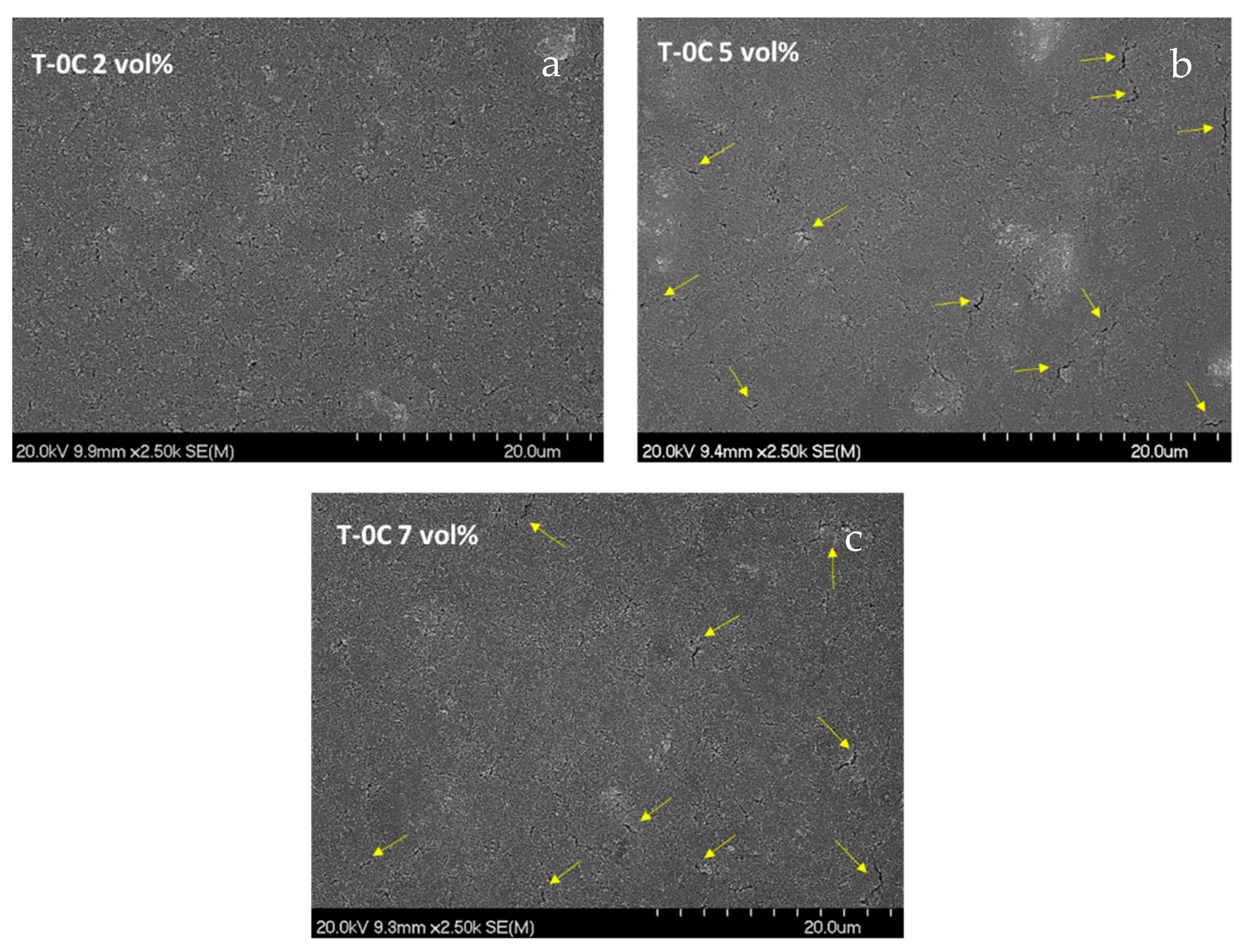
Figure 2 includes top-view micrographs of the TiO
2 coatings (labelled as T-0C) made with suspensions at 2, 5 and 7 vol.%. All these samples were prepared with three layers by following the multilayer strategy in combination with a thermal stabilization stage in a hot plate at 100 °C, to stabilize each layer, and a sintering treatment at 450 °C to consolidate the final microstructures.
The three formulations displayed good adhesion to the glass substrate. On the other hand, the T-0C 2 vol.% coating of
Figure 2a showed homogeneous, compact and crack-free surfaces, whereas the T-0C 5 vol.% and 7 vol.% coatings (
Figure 2b,c), respectively, did not. The yellow arrows included in both micrographs point at relevant defects as consequence of an excess of deposited material by effect of the viscosity rising. These cracks should be avoided since a wrong interpretation of the microstructural density could disturb the forthcoming comparison with the coatings modified with LCNFs. Therefore, the formulation of 2 vol.% was chosen as reference to prepare the following compound suspensions of TiO
2–LCNF.
The LCNFs, obtained from the revalorization of biomass residues by a specific procedure described elsewhere [
31], were previously characterized in aqueous media determining a negative surface for all pH ranges.
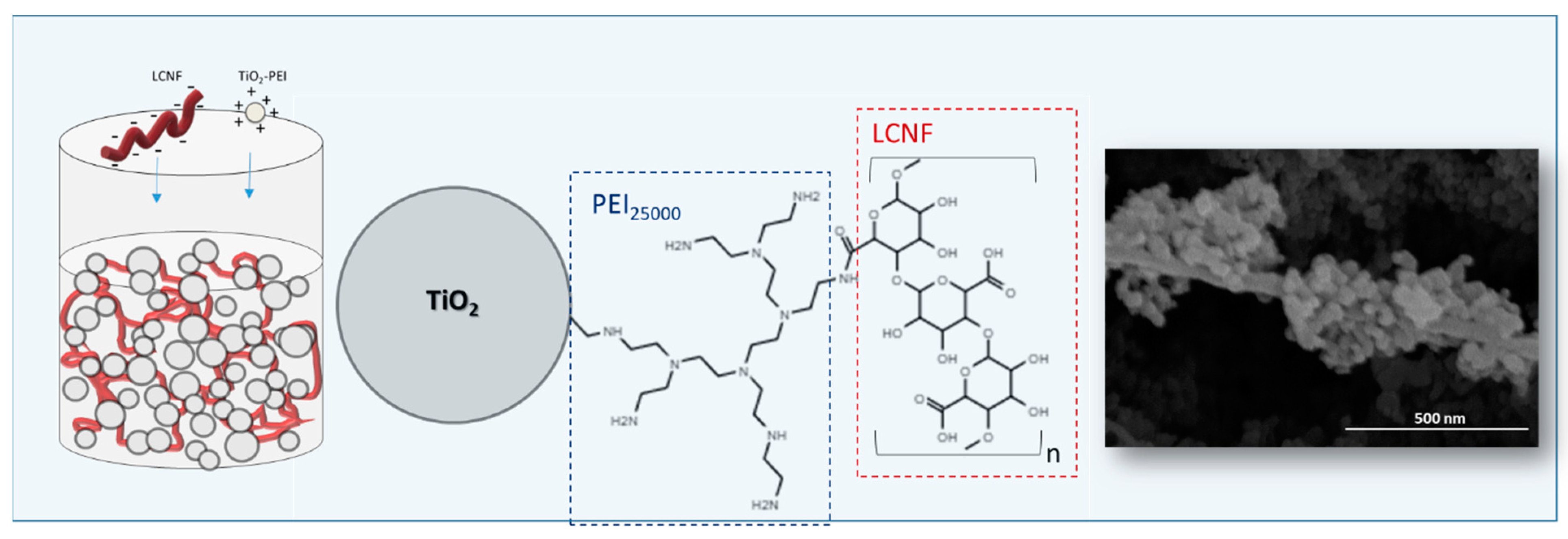
Figure 3 illustrates the colloidal approach followed for the preparation of the compound suspension. It consisted of a heterocoagulation process based on the electrostatic interaction between TiO
2 nanoparticles modified with PEI and nanofibers. How the negative charges of LCNF (−40 mV) at pH 8 are neutralized by the amine groups of the polyelectrolyte that was already adsorbed onto the added TiO
2 nanoparticles has been described. The fully covered fibers by nanoparticles reversed the surface charge sign to reach zeta potential values of 65 mV. Both the scheme and FE-SEM images included in this figure show details of the interaction mechanism and the resulting composite material.
Following a similar preparation protocol to the simple TiO
2 suspension, the TiO
2–LCNF structures were then centrifuged in order to favor a quick drying process after shaping. The aqueous solvent is substituted by ethanol by centrifugation, avoiding agglomeration phenomena. For this, the mixtures should always remain wet. Both the solid content and the viscosity of the TiO
2–LCNF suspensions were adjusted in organic medium in order to fulfill the shaping method requirements as well as to achieve compacted and uniform coatings without microstructural defects.
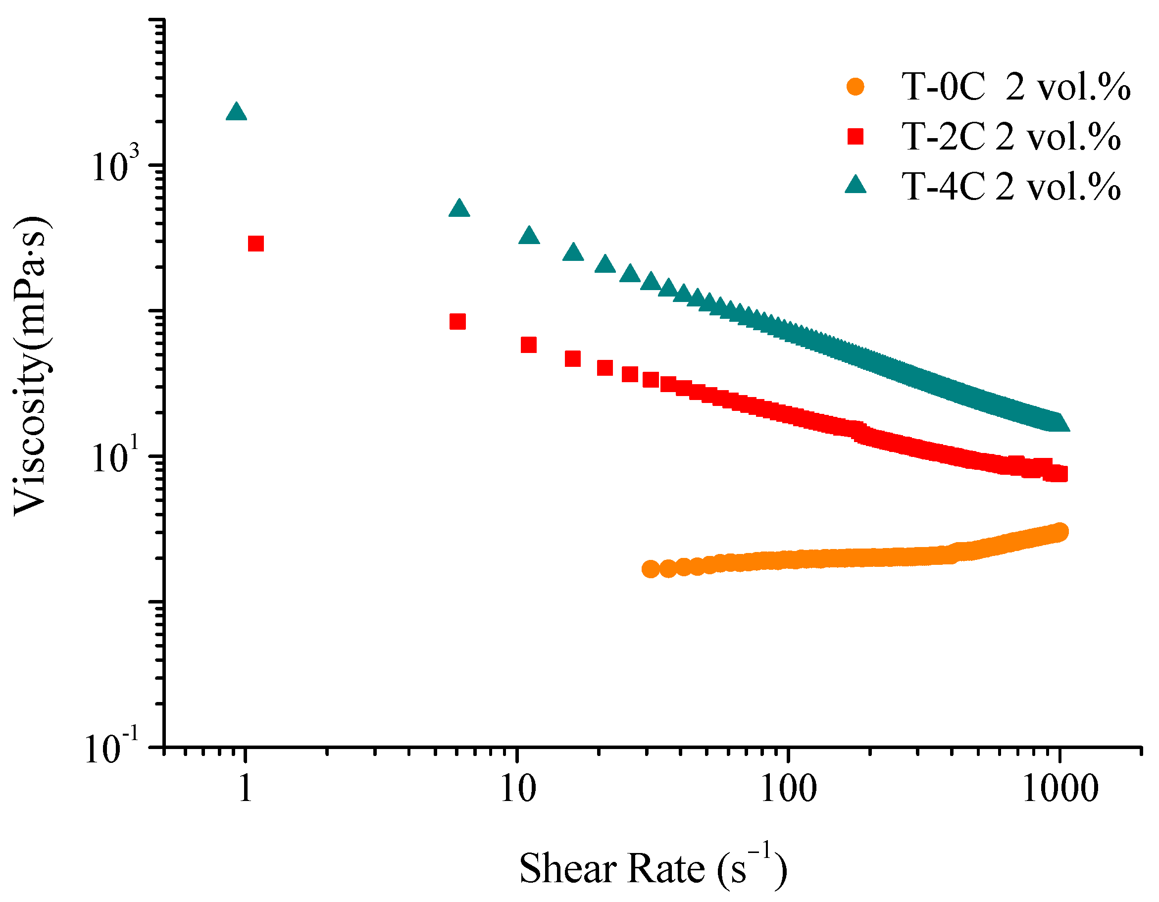
Figure 4 shows the flow curves at different LCNF contents, T-0C, T-2C and T-4C formulated at 2 vol.% of solid content in ethanol.
A significant shear thinning effect was observed when the LCNFs were included in the formulation, and the more the LCNF content increases, the greater the viscosity. The high values of viscosity at a low shear rate prevent segregation of phases in the resting stage during dipping, whereas the decrease in the viscosity with the shear rate is needed to favor the suspension flow during immersion/withdrawal of the substrates. The T-0C, T-2C and T-4C compositions were formulated at 2 vol.% to coat the substrates and evaluate their differences in terms of photocatalytic behavior. A suspension with higher content of LCNF (T-6C) was also formulated, maintaining the 2 vol.% solid content. The increase in viscosity limits the suspension handling and the dipping process. It is noteworthy that although the increase in viscosity, produced by the addition of a greater amount of LCNFs in suspension, favors the time consumption for manufacturing, an excess of LCNFs provokes heterogeneities and non-desirable defects. For this reason, 4 wt.% of LCNF was considered optimum for a reliable process According to our previous analyses (not included herein), there is a need to deposit our composite material by sequential deposition waiting for the drying of the layer prior to the dipping of a next layer. For this, samples were built with three, six and nine layers of the three suspensions by using a dipping speed of 2.5 mm/s.
To gain a better idea of the formation and growth of the prepared coatings, the mass values and thicknesses were analyzed as a function of the number of deposited layers and the viscosities of the mixed suspensions, respectively.
The mass values were plotted in
Figure 5a as a function of the number of deposited layers for the suspensions with different LCNF contents (T-0C, T-2C and T-4C). Furthermore, the thickness values of the coatings prepared with three, six and nine layers were graphed in
Figure 5b as a function of the viscosity measured at 100 s
−1. The three points of each curves correspond to the viscosity values measured for the T-0C, T-2C and T-4C suspensions. All results were obtained from the weight measurements and by cross-section FE-SEM images (not included herein). The summary of them is plotted as follows in
Figure 5.
As expected, the deposited mass values are higher as the number of layers increase. The dispersion and deviation of mass values were larger for the coatings built with nine layers and even for six-layered coatings. This means that there is a certain influence of both the surface and thickness of the previously deposited layers. However, it also depends on the flow behavior of the LCNF–TiO
2 suspension during layer-by-layer deposition. In fact, the higher the viscosity, the upper the coatings’ thickness.
Figure 5b confirmed that the increase in the viscosity resulted in higher thicknesses for the three types of coatings. The slope of the curve corresponding to the three first layers is less pronounced than the slopes of the curves of the coatings made with six and nine layers, which is evidence of the large influence of the viscosity in the layer-by-layer process when the amount of LCNF increases. The fact of having deposits slightly heavier when deposition is performed on a rough surface (from a previous layer) suggests that there is another process involved in the deposit growth. Ferrari et al. reported elsewhere [
32] that the existence of this additional contribution is due to the solvent filtration in a spongier substrate during deposition.
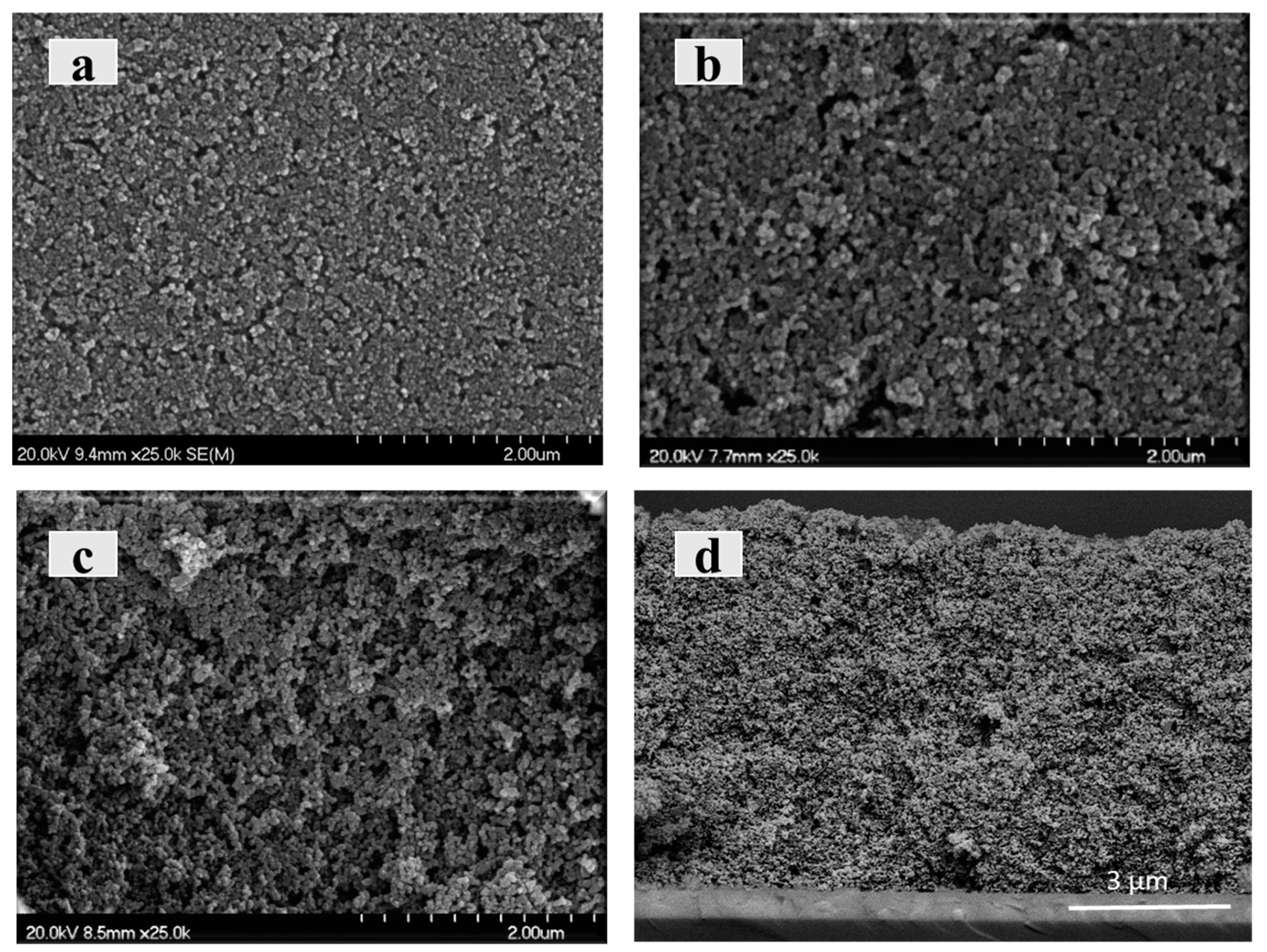
After the shaping process, the prepared coatings were sintered in air at 450 °C, producing the biotemplate decomposition and creating the specific porosity. At this temperature, the microstructures were also consolidated by forming ceramic necks among the nanoparticles. At this point, it is outstanding to see how the coatings continue to be free of cracks and keep their adherence with the substrate. The stress accumulation within the films is cushioned during the thermal stabilization steps carried out in the deposition of the multiple layers. To evaluate the morphological differences of the consolidated microstructures of the immobilized photocatalyst,
Figure 6 includes a comparison of the coatings made with three layers from the T-0C, T2C and T-4C suspensions (
Figure 6a–c, respectively). In addition, a cross-section view of a coating prepared with six layers from the T-4C suspension has been included as
Figure 6d.
These micrographs confirmed homogeneous and crack-free microstructures as a result of the successful development of colloidal processing stages, including shaping and sintering. The increase in roughness and porosity within the microarchitectures made with suspension at higher LCFN contents is visually remarkable. Their removal after sintering generated a noteworthy rise in the exposed surface of the immobilized photocatalyst. Although no significant differences were found on the surface appearance of other top-view micrographs made with six and nine layers, the increase in the thickness values enables us to have a larger amount of immobilized photocatalysts exposed to the reactant. The cross section of
Figure 6d certifies the microstructural continuity and porosity along the whole 9 µm thickness, which will favor the dye impregnation.
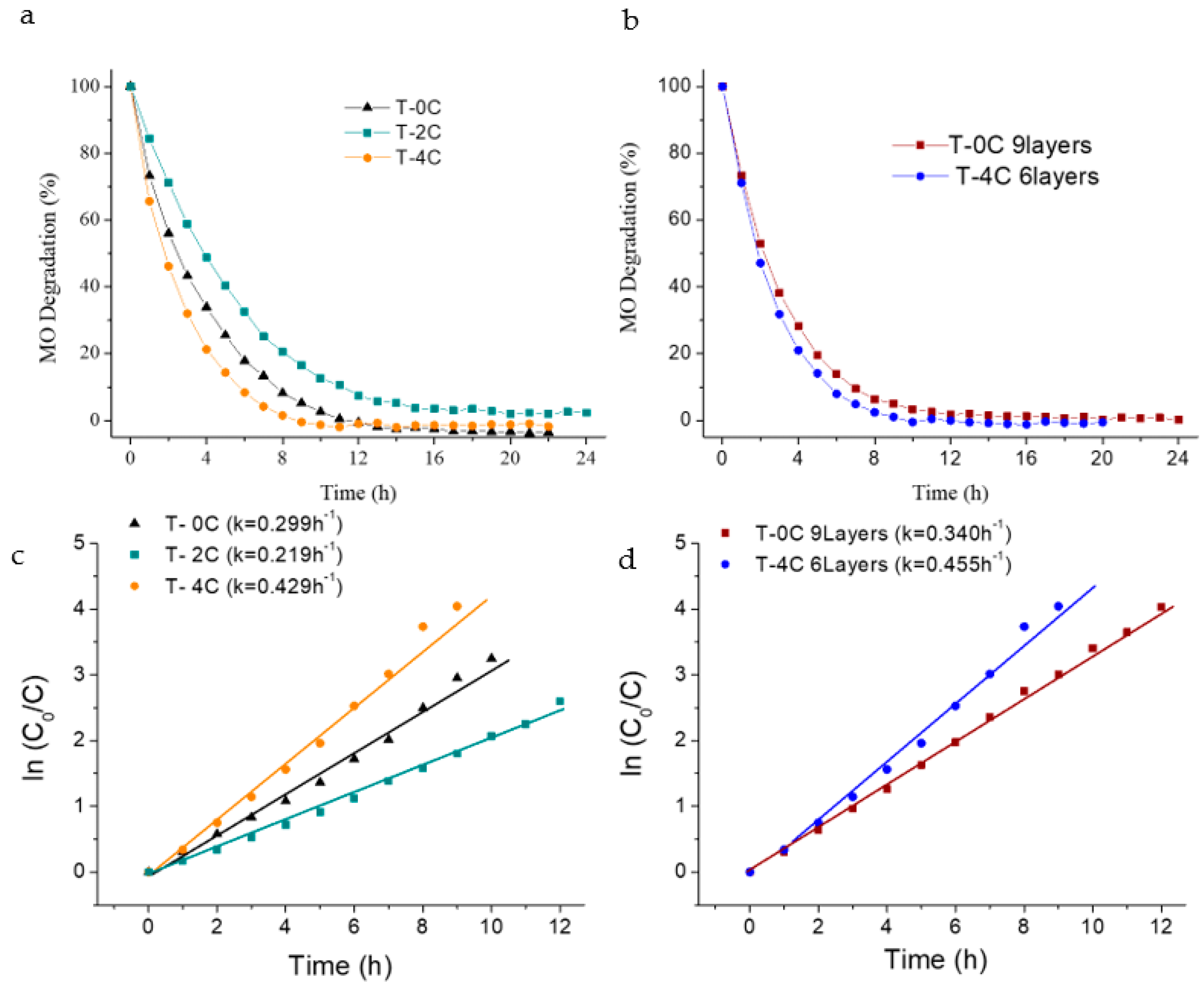
MO degradation measurements were carried out by direct immersion of the covered supports in order to evaluate the influence of having different microstructural appearances in the photochemical response (
Figure 7a,b). Preliminary photolysis and dark tests showed that neither photolysis nor adsorption processes occur. The kinetic curves,
Figure 7c,d, corresponding to the photocatalytic oxidation of MO were additionally fitted by the Langmuir–Hinshelwood model:
where
r is the oxidation rate of the reactant,
C is the concentration of the reactant,
t is the illumination time,
k is the reaction rate constant, and
K is the adsorption coefficient of the reactant. As the initial chemical concentration of the dye (
C0) was low, the above equation was simplified to an apparent first-order equation:
Figure 7a quantifies the MO photodegradation capability of the coatings made with three layers (deposited mass and thicknesses around 1.2 ± 0.3 mg and 4.0 ± 0.5 µm, respectively). The T-4C coating displayed the best photocatalytic activity due to the higher exposed surface area, as already seen in
Figure 6c. In addition to this, the microstructural modification-type was also noticeable for T-2C coating,
Figure 6b; it displayed a partial photoactivity reduction. This behavior was probably due to a slower recombination of the photogenerated electron-hole pairs [
11,
14], which was increased by nanoparticle connectivity losses in more porous structures. In the case of the T-4C coating, the major increase in the exposed surface area compensates the recombination lack, and even results in higher contribution, which improves the final behavior. Although 100% of dye was completely removed from the solution with the three microstructure-types, the degradation rate was different as a function of the LCNF amount used. The T-4C composition displayed a faster response than the other two,
Figure 7c. The k value of the T-4C coating (0.429 h
−1) was higher than the
k values for the T-0C and T-2C samples (0.299 and 0.219 h
−1). The first degraded 100% of the dye in less than 6 h, whereas the other ones required longer times. Furthermore, the effects of the thickness and deposited mass were also evaluated in terms of photoactivity by comparing the T-4C sample prepared with six layers with the unmodified coating, T-0C, built with nine layers. In both samples, the photoactive mass was around 2.5 ± 0.15 mg and thicknesses were 8.5 ± 0.5 µm.
Figure 7b shows better MO photodegradation capability in the porous coating modified with the biotemplate. The LCNF-free coating, prepared with a thickness of nine layers, exhibited a slower degradation rate than the T-4C coating, built with fewer numbers of layers (
Figure 7d). The
k values varied from 0.340 to 0.455 h
−1 between the non-template and the modified coatings. This means that a relevant save in time consumption is also happening with the inclusion of the biotemplate since it is not necessary to deposit a higher mass to achieve better results—a lesser amount of immobilized photocatalyst, whilst being better exposed, is enough.
All coatings maintain being firmly joined to the glass substrate, without releasing when pulling out with scotch tape. Furthermore, the mass of the dried samples was measured before and after the photocatalytic tests, proving film preservation, and confirming the adhesion of the film to the substrate and cohesion of the layer-by-layer processed films. On the other hand, a second photocatalytic test of the T4C-6 layers coating was made in order to provide initial ideas about the reusing capability. No significant differences were observed in terms of photoactivity and mass preservation, which is very important from the application point of view.
Finally, results were compared with the literature, although comparison is not always straightforward as not all studies were performed under the same conditions. Keeping this in mind, it is possible to say that the results obtained under our approach (using commercial particles and templates obtained from natural-derived resources) are competitive with the other pure TiO
2 materials (no composites) reported previously in the literature, which were prepared through more complex methodologies such as sol–gel.
Table 1 shows an overview of some works. In addition, it is remarkable that this reported processing strategy could be applied to immobilize other synthetized semiconductors with better intrinsic photocatalysis properties.
3. Experimental
As-received TiO
2 nanoparticles (Aeroxide P25, Evonik Degussa GmbH, Germany, S
BET: 50 ± 15 m
2/g
−1, d: 4.2 g/cm
−3, 80:20 anatase:rutile), were initially dispersed in aqueous media at pH 8, including a 6 wt.% (referred to the weight of TiO
2) of branched polyethylenimine (PEI, pKa 8.6, Mw 25,000 mol/g, Aldrich, Germany) as dispersant. The mass of nanoparticles was adjusted to achieve solid contents ranging from 2 vol.% to 16 vol.%. All TiO
2 suspensions were then ball-milled for 120 min using Al
2O
3 balls of 1 cm in diameter in order to break the possible agglomerates from the commercial powder. More details about the stabilization process in liquid media are included in previous works [
35,
36]. After the surface modification of TiO
2 nanoparticles, the aqueous solvent of suspensions was changed by an organic one in order to favor the drying process of the future coatings avoiding possible microstructural defects. After the surface modification of TiO
2 nanoparticles, the aqueous solvent of suspensions was removed by centrifugation and changed by an organic one (ethanol) in order to favor the drying process of the future coatings avoiding possible microstructural defects. The rheology of these TiO
2 suspensions was firstly studied in order to define reference conditions to prepare dense TiO
2 coatings, without including the LCNF templates, and later compared with porous coatings, prepared with suspensions of LCNF-TiO
2. A Haake Mars rheometer (Thermo Scientific, Germany) with a double-cone plate fix of 60 mm in diameter and an angle of 2° (DC60/2°) was used. Tests were performed in a control rate mode (CR) shearing up from 0 to 2000 s
−1 in 2 min, dwelling at 2000 s
−1 for 1 min and shearing down to 0 s
−1 in 2 min and control stress mode (CS) increasing stress from 0 to 15 Pa in 2 min and decreasing to 0 Pa at the same time. All tests were performed in room conditions. Viscosity as a function of solid loading was plotted in order to correlate the effective viscosity with the maximum packing volume fraction of solid–liquid suspensions. The resulting curve was adjusted by the Krieger–Dougherty (K–D) model according to the following equation:
where ∅
max is the maximum packing fraction,
η is an empirical exponent and
ηs is the viscosity of the solvent (mPa/s). The exponent
n and the maximum packing fraction, ∅
max, for the suspension were estimated by using the K–D equation.
On the other hand, as-prepared LCNF, obtained by a conventional production method from biomass residues of wheat straw, were separately dispersed in aqueous media at pH 8 with the aid of a mechanical disgregator for 5 min at 590 rpm. More details about the stabilization of LCNF were previously reported elsewhere [
37]. The preparation of the resulting suspensions was carried out in aqueous media by inducing a heterocoagulation process between both colloidal systems. For this, mixed suspensions with percentages of LCNF ranging 0–4 wt.%, with respect to the amount of TiO
2 nanoparticles, were formulated. After mixing by mechanical stirring, the aqueous solvent of the suspension was also changed by ethanol following the same strategy as the TiO
2 suspensions without LCNF. The solid contents of these mixed suspensions were adjusted up to values around 1–2 vol.% in order to adapt their viscosity to the shaping technique. Further rheological measurements were made in similar conditions to the previous formula. For comparative purposes, all suspensions used in this work, both TiO
2 without LCNF and the TiO
2 with 2 and 4 wt.% of LCNF, have been labeled as T-0C, T-2C and T-4C, respectively. All of them were shaped on glass substrates by dip-coating technique with a withdrawal rate of 2.5 mm/s. The thicknesses of the coatings were varied by sequential depositions of different layers. The TiO
2 mass varied from 0.9 to 5.6 mg. A thermal stabilization step of 2 min over a hot plate at 100 °C was made after depositing each fresh film. Additionally, the LCNF–TiO
2 coatings were sintered in air atmosphere at 450 °C for 15 min, with heating and cooling rates of 5 °C/min. The consolidated microstructures were examined by a field emission scanning electron microscope (FE-SEM Hitachi S-4700, Japan).
Photocatalytic performances of the T-0C, T-2C and T-4C coatings were evaluated by the degradation of methyl orange (MO) under the effect of a solar light simulator (Oriel, model 96000) coupled with a Keithley 2010 multimeter which records the output voltage signal from the detector every 10 min using a Visual Basic homemade code. The solar light source of the equipment was an Xe-arc lamp (Osram XBO 450 W) with commercial AM 6197 filter.
The tests were performed in a quartz reactor vessel, with a lid, which contained a specific volume (25 mL) of an aqueous solution of 3 mg/L of MO at pH 2. All measurements were performed by introducing the coatings in the MO solution under continuous stirring and irradiation. Some previous dark tests were additionally carried out to ensure that the MO degradation was only caused by the prepared coatings and not by light irradiation and/or adsorption. Degradation phenomena were monitored using a home-made system described previously elsewhere [
38]. A narrow bandpass filter centered at 500 nm and bandwidth of 10 nm (Thorlabs, FB-500-10 full width at half maximum) was placed in front of a biased Silicon Photodetector (Thorlabs DET100A). The filter limits allow the light transmission to be in a wavelength range that matches the absorption band of MO (508 nm). Therefore, the intensity of the light at the detector allows one to measure the degradation of MO. All of the elements were installed on an optical table to ensure stability; they are optically isolated in the dark to avoid the presence of other light sources.


