Article

Hierarchical Graphitic Carbon-Encapsulating Cobalt Nanoparticles for Catalytic Hydrogenation of 2,4-Dinitrophenol

by
Hassan H. Hammud
1,*,
Hassan Traboulsi
1,*,
Ranjith Kumar Karnati
1,
Syed Ghazanfar Hussain
2 and
Esam M. Bakir
1,3
1
Department of Chemistry, College of Science, King Faisal University, P.O. Box 400, Al-Ahsa 31982, Saudi Arabia
2
Department of Physics, College of Science, King Faisal University, P.O. Box 400, Al-Ahsa 31982, Saudi Arabia
3
Department of Chemistry, Faculty of Science, Ain shams University, Cairo 11566, Egypt
*
Authors to whom correspondence should be addressed.
Catalysts 2022, 12(1), 39; https://doi.org/10.3390/catal12010039
Submission received: 7 November 2021 / Revised: 16 December 2021 / Accepted: 21 December 2021 / Published: 30 December 2021

Abstract

:
Cobalt hierarchical graphitic carbon nanoparticles (Co@HGC) (1), (2), and (3) were prepared by simple pyrolysis of a cobalt phenanthroline complex in the presence of anthracene at different temperatures and heating times, under a nitrogen atmosphere. The samples were used for the catalytic hydrogenation of 2,4-dinitrophenol. Samples (1) and (3) were prepared by heating at 600 °C and 800 °C respectively, while (2) was prepared by heating at 600 °C with an additional intermediate stage at 300 °C. This work revealed that graphitization was catalyzed by cobalt nanoparticles and occurred readily at temperatures of 600 °C and above. The nanocatalysts were characterized by Scanning Electron Microscopy SEM, energy dispersive X-ray analysis EDX, Raman, Xrd, and XPS. The analysis revealed the presence of cobalt and cobalt oxide species as well as graphitized carbon, while TEM analysis indicated that the nanocatalyst contains mainly cobalt nanoparticles of 3–20 nm in size embedded in a lighter graphitic web. Some bamboo-like multiwall carbon nanotubes and graphitic onion-like nanostructures were observed in (3). The structures and chemical properties of the three catalysts were correlated with their catalytic activities. The apparent rate constants kapp (min−1) of the 2,4-dinitrophenol reductions were 0.34 for (2), 0.17 for (3), 0.04 for (1), 0.005 (no catalyst). Among the three studied catalysts, the highest rate constant was obtained for (2), while the highest conversion yield was achieved by (3). Our data show that an increase in agglomeration of the cobalt species reduces the catalytic activity, while an increase in pyrolysis temperature improves the conversion yield. The nanocatalyst enhances hydrogen generation in the presence of sodium borohydride and reduces 2,4-dinitrophenol to p-diamino phenol. The best nanocatalyst (3) was prepared at 800 °C. It consisted of uniformly distributed cobalt nanoparticles sheltered by hierarchical graphitic carbon. The nanocatalyst is easily separated and recycled from the reaction system and proved to be degradation resistant, to have robust stability, and high activity towards the reduction reaction of nitrophenols.

1. Introduction

Cobalt–carbon nanostructures are of great interest because of their wide and important applications in batteries [1], supercapacitors [2], oxidation [3], and hydrogenation [4] catalysis and water treatment [5,6].
Many methods have been developed so far in order to prepare cobalt–carbon nanostructures. For example, carbon nanotubes (CNTs) were prepared with cobalt catalyst by arc discharge [7], pulsed laser vaporization [8], and chemical vapor deposition (CVD) [9]. However, these methods face the challenge to produce carbon nanostructures in large amounts with specific morphologies that serve unique applications. They are also sophisticated and expensive, requiring catalyst, inert gas, carbon-source gas like acetylene and reducing hydrogen gas. However, pyrolysis methods are simple and cheap. They involve the pyrolysis (in inert atmospheres) of transition metal complexes (which provides the metal nanoparticles catalysts for graphitization), and a carbon source (from ligands or external carbon sources). Depending on the precursor’s structures and heating conditions, several nanostructures can be obtained. While pyrolysis of cobalt carbonyl phenyl–alkyne complexes gave carbon–cobalt nanorods or nanospheres, pyrolysis of cobalt carbonyl graphene–alkyne complexes gave multiwalled carbon nanotubes (MCNTs) [10]. Additionally, pyrolysis of polyphenylene dendrimer/cobalt complexes can produce CNTs, carbon–cobalt nanorods, or carbon/cobalt nanospheres [11].
Nowadays, it is of great importance to find a suitable, abundant, and low-cost catalyst for the reduction of nitrophenols into anilines, since anilines have wide applications in industry, such as in the preparation of pesticides, pharmaceuticals, dyes, pigments, agrochemicals, plastics, and rubbers [12]. Palladium [13] and a gold-based catalyst [14] were used for selective hydrogenation of nitrophenols; however, they are expensive for industrial application.
The mechanism of the catalytic reduction of nitrophenols has been proposed by several studies [15,16,17]. Makaudi et al. proposed a catalytic reduction mechanism based on the cyclic voltammetry determination of the electrochemical behavior of the species involved in the reaction [18,19,20].
Cobalt oxide N-graphene/activated carbon nanomaterials Co3O4-NGr@C prepared by pyrolysis of cobalt pyridine derivatives acted as a selective catalyst for the hydrogenation of nitroarene derivatives under demanding conditions (at 100 °C for 11–17 h) in THF solvent, using triethylamine Et3N and formic acid as the hydrogen source [21]. However, when hydrogen gas was used at high pressure (5 bar and temperature 110 °C), the reaction time was only 4 to 12 h in the THF solvent [22]. A cobalt(0) nitrogen-doped carbon Co@NC-700 catalyst obtained by the pyrolysis of Co metal’s organic framework showed remarkable performance for the hydrogenation of p-nitrophenol to p-aminophenol using NaBH4 as a reducing agent in water [23]. Recently, cobalt oxide/hydroxide materials were also proved to be effective for the selective catalytic reduction of nitrophenols [24].
There have been few reports on the catalytic reduction of 2,4-dintrophenols. The catalysts used were Au nanoparticles decorated on activated coke [15], core-shell microgel-Ag nanoparticles [25], Ag nanoparticles at chitosan-functionalized graphene oxide [18], Ni nanoparticles on electro-spun polycaprolactone/chitosan nanofibers [26], Au nanoparticles, and Ag nanoparticles [27].
There is still a need to seek nanocatalysts that can achieve the hydrogenation of dinitrophenols with a high recyclability in short time periods at mild conditions. In the present study, we investigated the catalytic reduction of 2,4-dinitrophenol using cobalt–carbon nanoparticles Co@HGC prepared by pyrolysis of a cobalt phenanthroline complex under different pyrolysis temperatures in the presence of additional carbon sources.

2. Results and Discussion

We have previously reported the preparation of porous cobalt–carbon nanostructures by pyrolysis of cobalt complexes and studied their applications in water treatment. The nanomaterials were prepared in a quartz tube furnace at 600 °C in the presence of a carbon source, demonstrating a high capacity for the removal of malachite green (492 mg/g) [6]. In a second study, we used silica as a support in the pyrolysis experiment in a box furnace at 850 °C, and obtained cobalt–carbon/silica nanocomposite CoC@SiO2-850 nanostructures with durable and regenerative properties. The capacity for removing crystal violet was 214 mg/g [28].
In the present study, we have prepared hierarchical graphitic carbon-encapsulating cobalt nanoparticles Co@HGC, based on optimized conditions. The new nanomaterials can act as a heterogenous catalysis for the hydrogenation of 2,4-dinitrophenol at mild conditions, in short time periods, and with high recyclability.

2.1. Material Preparation

[Co(phen)2Cl2]1.5CH3CN was prepared [29], and used as a catalyst precursor for the synthesis of cobalt–carbon nanoparticles. In addition to the phenanthroline ligands that act a carbon source, anthracene was additionally used as an external source of carbon. Three experimental conditions were used for the pyrolysis of the cobalt–phen complex with anthracene under a reduced nitrogen pressure of 0.02 atm.
Sample (1) was obtained in an open crucible at 600 °C for 8 h, where the volatiles from decomposing materials have less chance to redeposit on the metal nanoparticles. Sample (2) was prepared in a method similar to (1) by pyrolysis at 600 °C for 8 h, however, after heating for 2 h at an intermediate stage of 300 °C in a covered crucible. The decomposition of the complex, and thus the formation of cobalt nanoparticles, started at this intermediate stage. Finally, (3) was also prepared in a covered crucible, but by heating at higher temperature 800 °C for only 5 h, since higher temperature favors graphitic carbon formation.
The best method for catalyst preparation is the one that can generate highly active species of small-size metal nanoparticles surrounded with well-developed graphitic structures [22]. This is supported by the catalytic hydrogenation results obtained in this work. Optimization of the pyrolysis step showed that the temperature gradient and the heating time at the maximum temperature significantly influenced the activity and selectivity of the catalyst. All pyrolysis experimental conditions played a role in obtaining the best performing catalyst. These conditions included the presence of the intermediate stage of heat necessary to prepare the metal nanoparticles (the precursors for the formation of graphitic carbon); the time of heating; and the value of the maximum temperature in the final stage, which is necessary to develop the graphitic carbon structures. Therefore, during pyrolysis, organic ligand decomposes and evaporates to the gas phase, then becomes carbonized. The graphitic structure provides a robust shelter around metal nanoparticles and reduces their degradation during the catalytic process. Closed systems can ensure a long residence time of volatile carbons above the cobalt(0) nanoparticles which catalyze the graphitization-surrounding carbon.
The graphitic shell can prevent cobalt nanoparticles from further agglomerations which reduce the catalytic efficiency. However, there are limitations for the uses of catalysts with thick graphite shells, which, due to diffusion limitations, render the active cobalt sites of the nanoparticles hardly accessible by reactants.
In this work, the best catalyst structures were obtained by carrying out the pyrolysis at 600 °C (with an intermediate stage at 300 °C) or at 800 °C. This can be inferred from the SEM and TEM results.
We have also performed extra pyrolysis at two temperatures. At 500 °C, the graphitization reaction was not complete and little hierarchical graphitic carbon was obtained. Graphitization was evident at 600 °C and above. While at 1000 °C, the product was degraded into ash and volatilized.
We report in Supplementary Materials Table S1 the effects of carbon source, time, and heating temperature, the effect of intermediate stage, and the SEM figures of nanoparticles A, B, C, D, E, F and (1), (2), and (3). Sample (1)-acid was prepared by treating (1) with 10% HCl. The white cobalt species were lost from the structure, leaving empty pores, SEM images (Supplementary Materials Table S1).
Figure 1 is a descriptive projection of the SEM images of selected pyrolyzed products in order to clarify their morphologies. Temperature of pyrolysis for samples (A) is 500 °C, for (1) and (2) it is 600 °C, while for (3) it is 800 °C; Figure 1a–d respectively. At low temperatures, the cobalt nanoparticles in (A) are immersed in the carbon support layer, with few cobalt particles exposed; moreover, the hierarchical carbon is not well developed as in the other nanostructures. At 600 °C, (1) and (2) showed hierarchical carbon, but more agglomerated particles in the case of (1), where an open lid crucible is used and less equilibration occurred between the vapor and solid state. At higher temperatures like 800 °C, it is expected to have a higher activity for catalyst (3) because of less agglomeration, well dispersed and smaller cobalt nanoparticle sizes compared to (1) and (2), and containing well-developed hierarchical carbon.

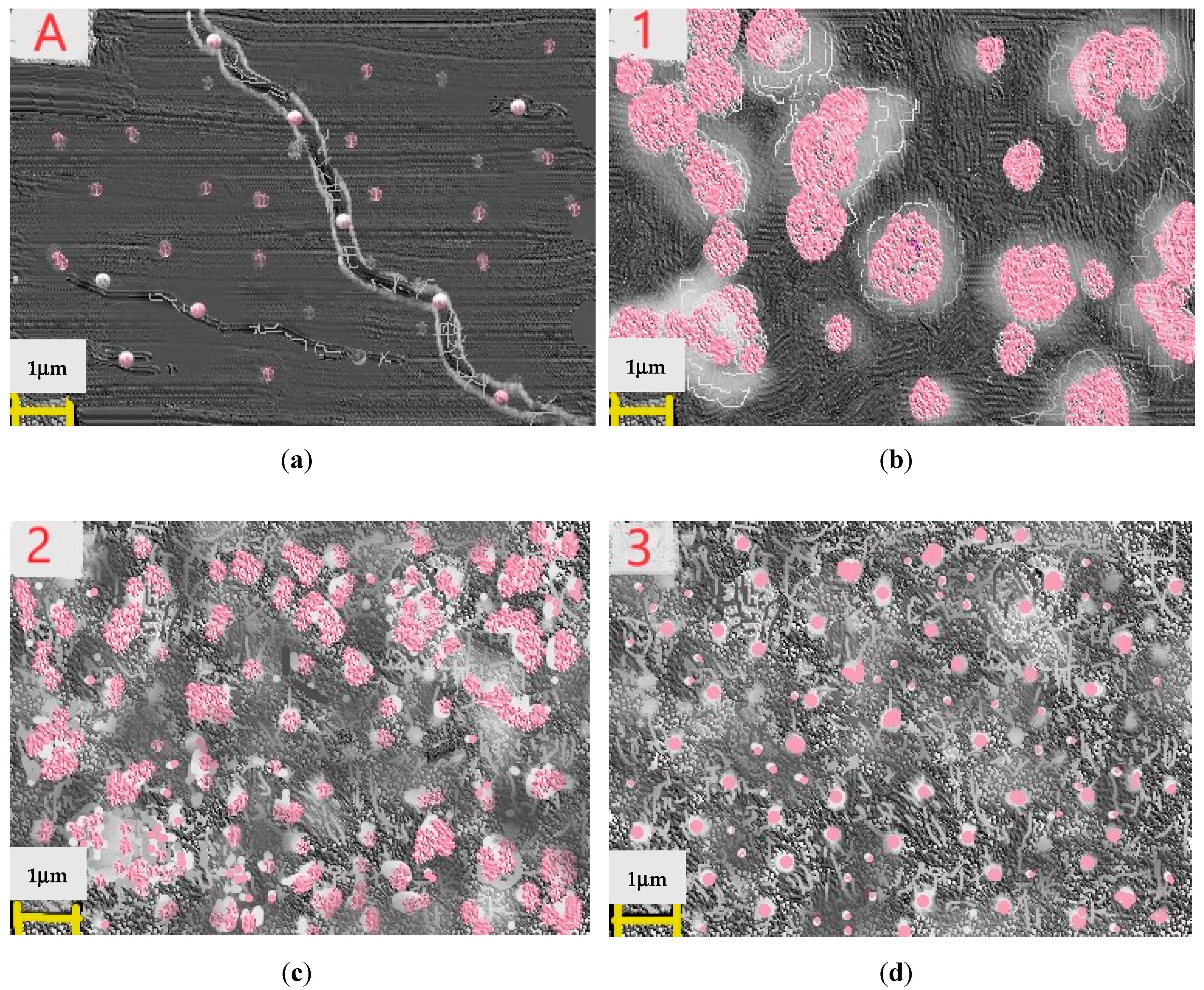
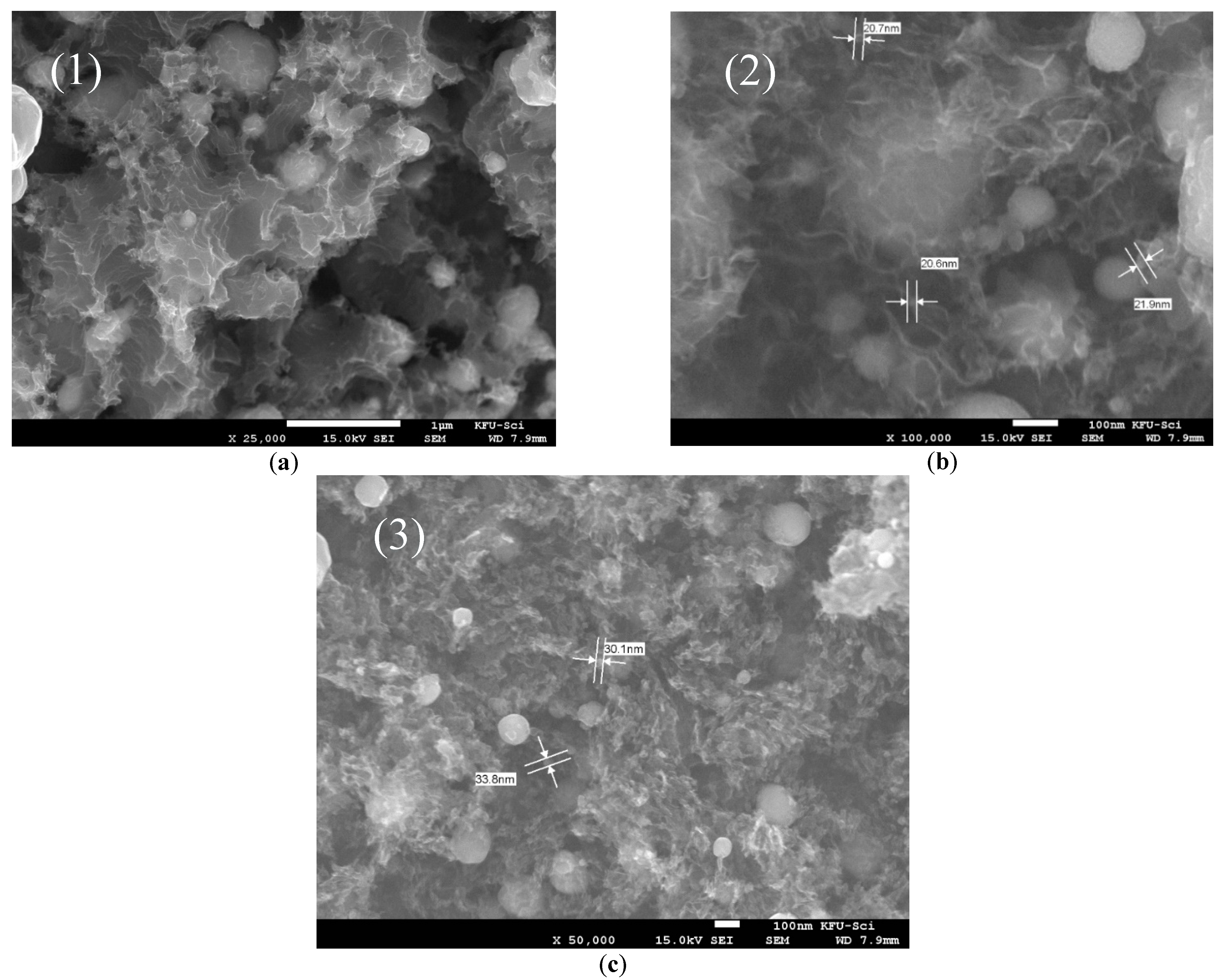
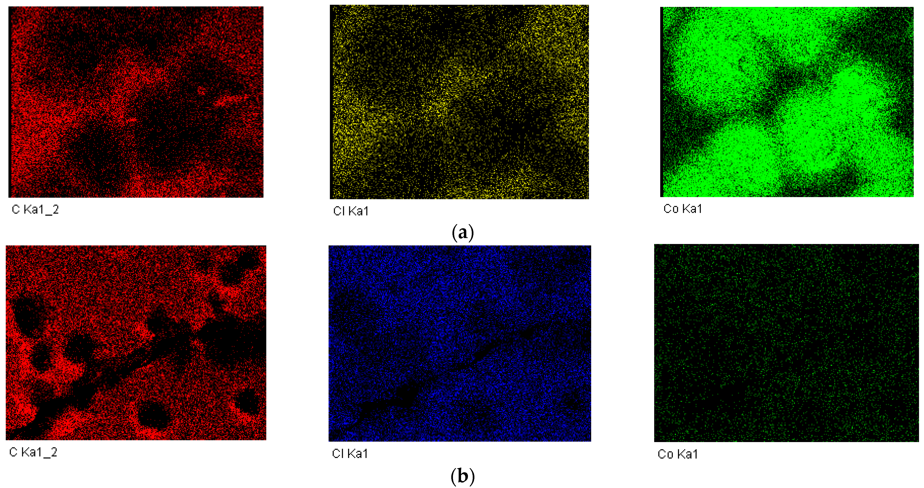
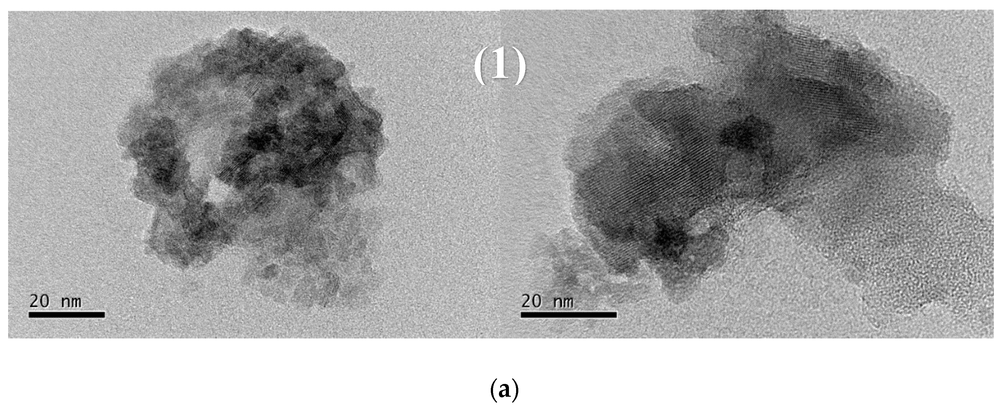
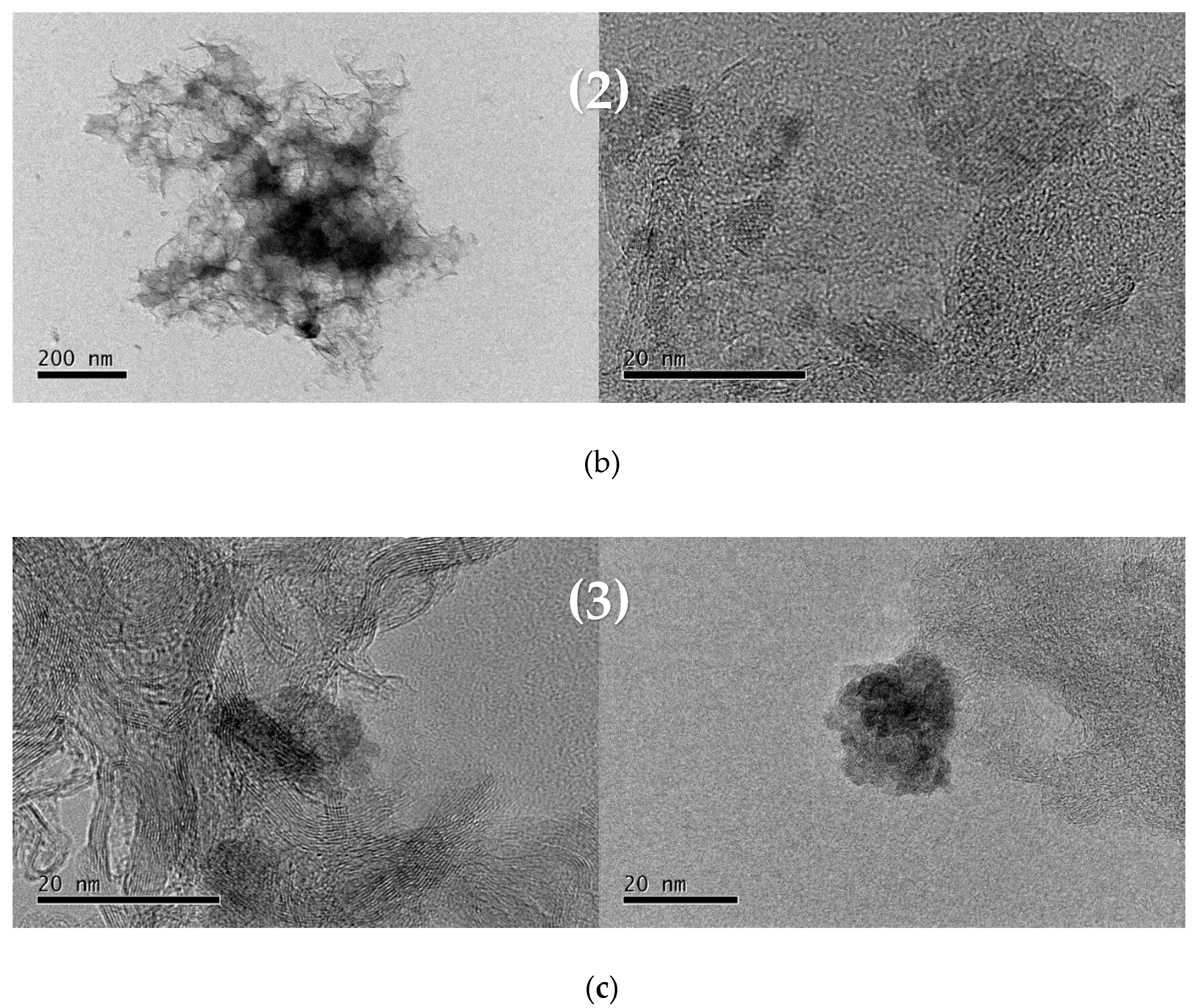
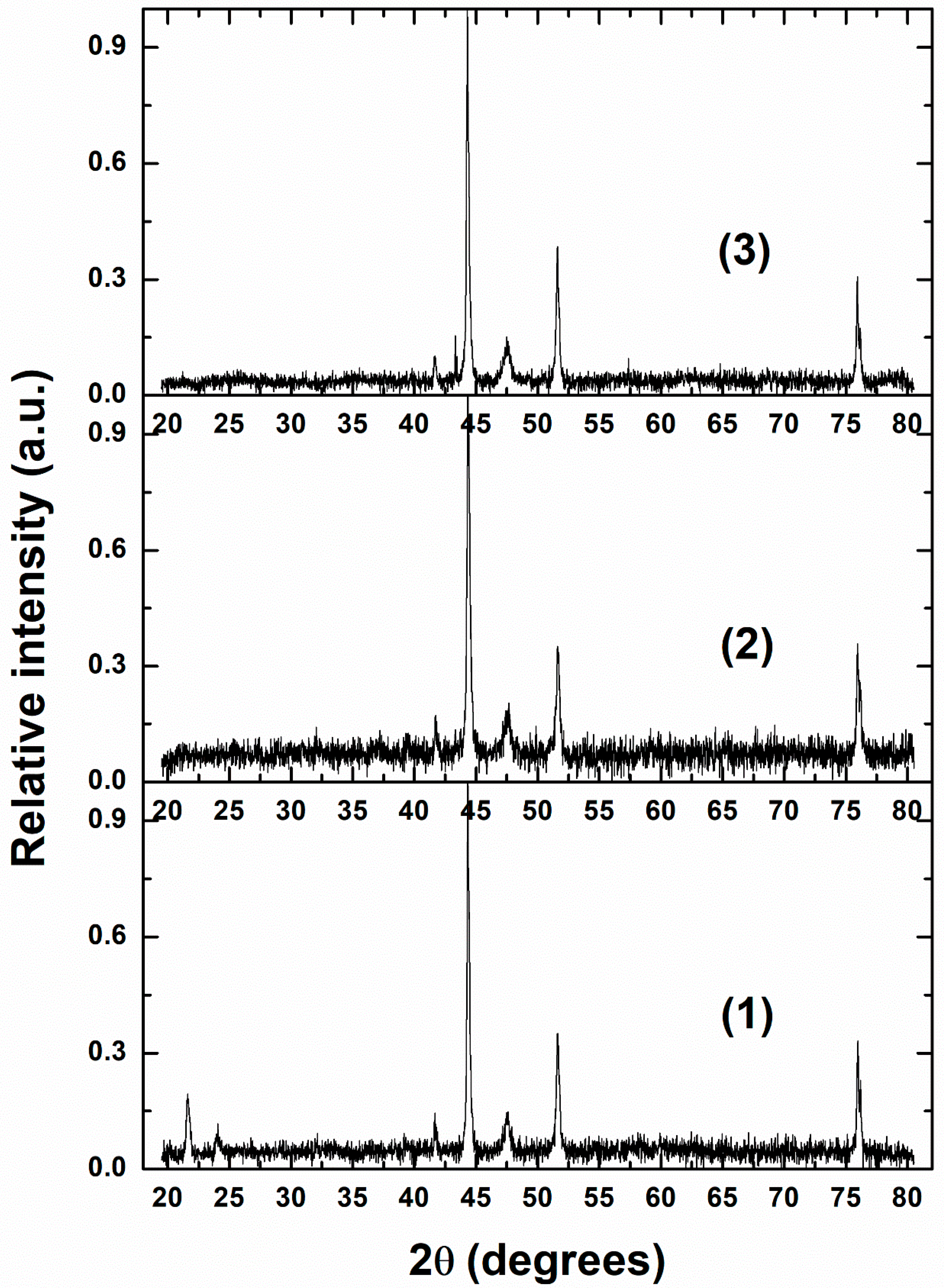
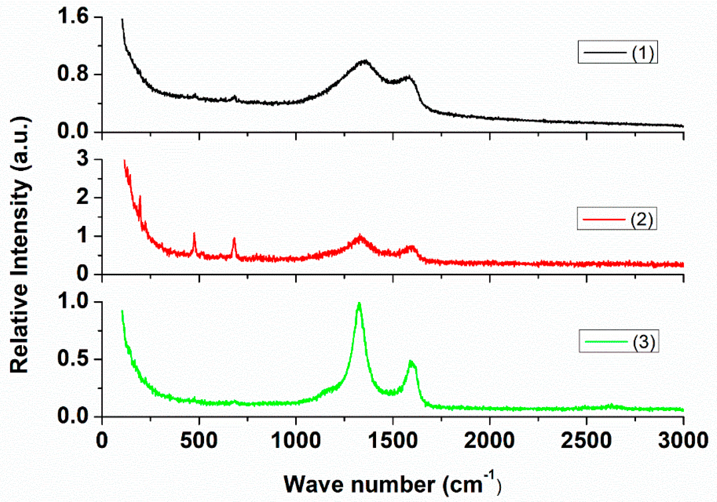
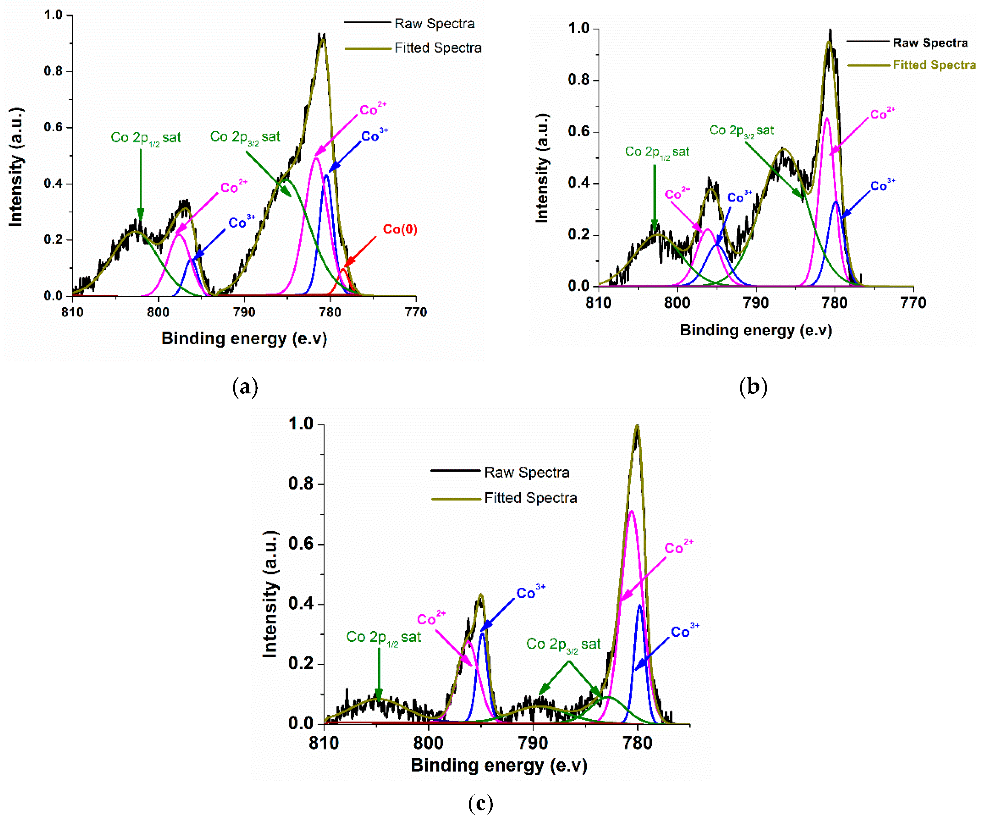
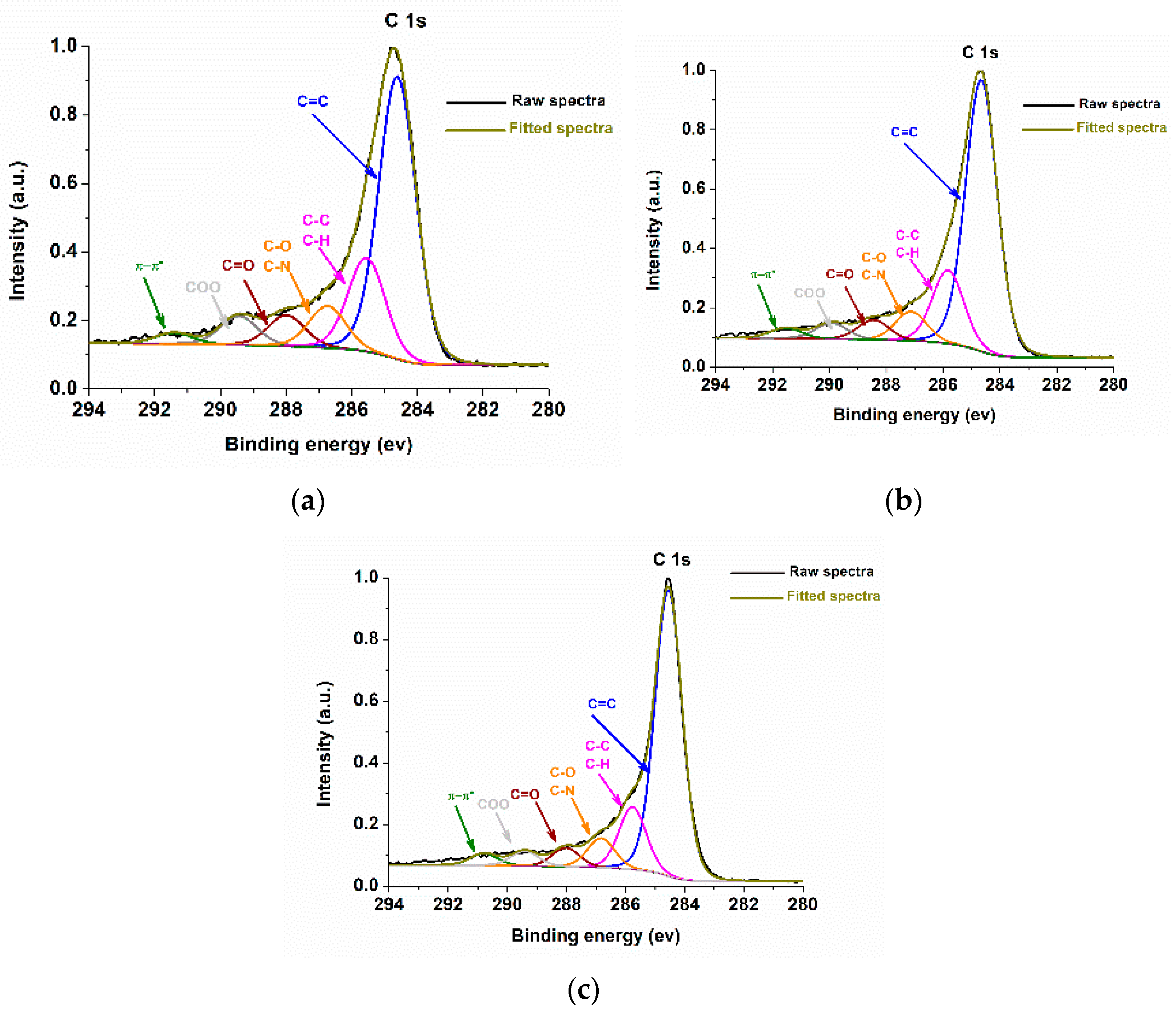
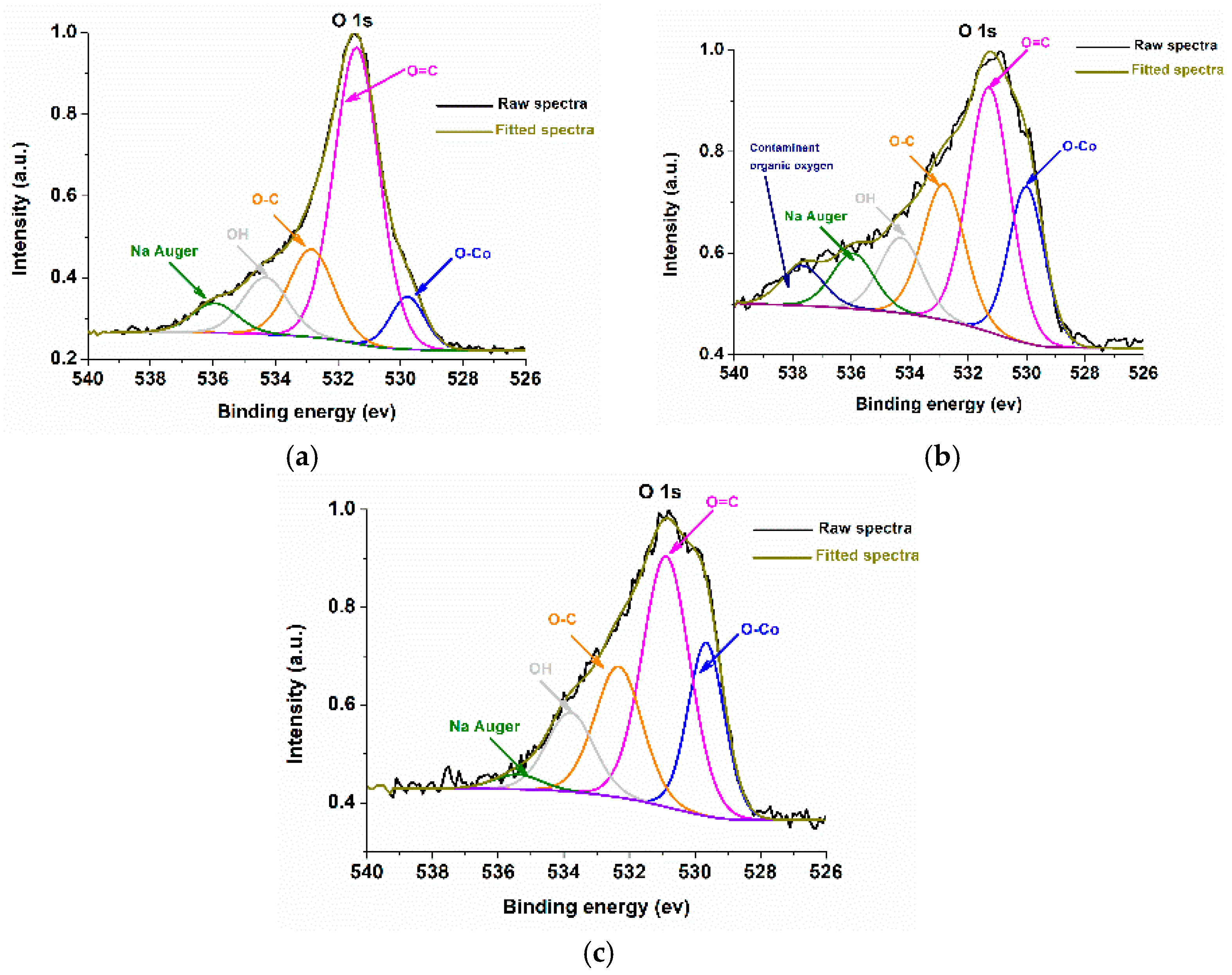
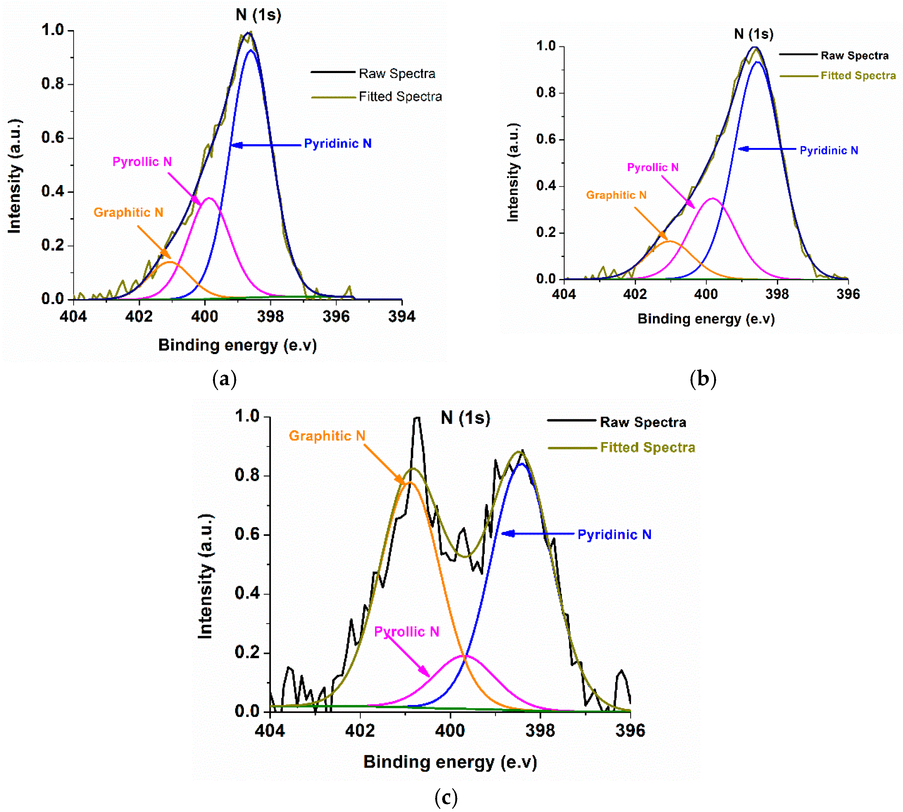
2.2. Characterizations of Nanomaterials (1), (2), and (3)
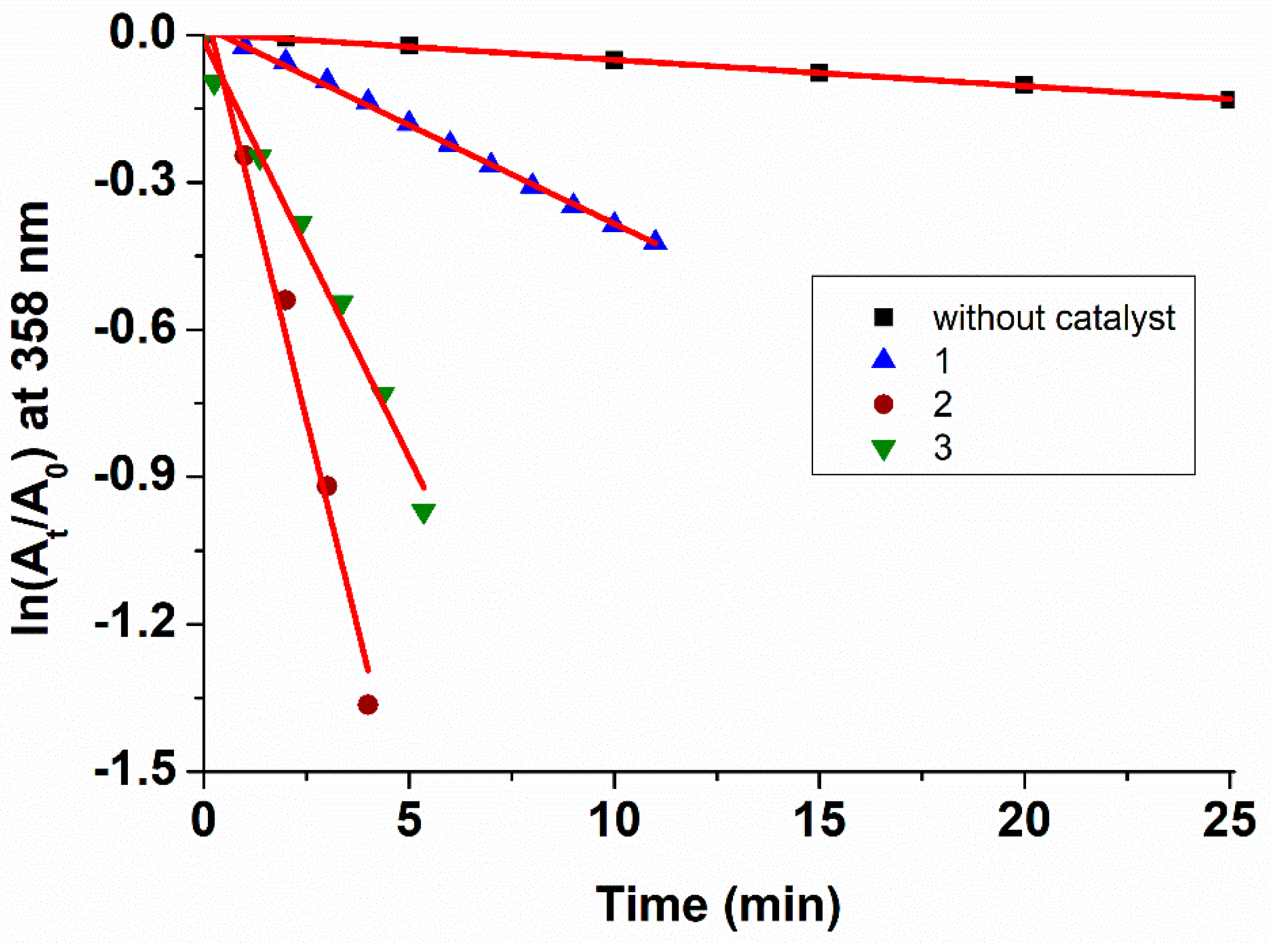
As shown in the SEM of Co@HGC, (Figure 2), sample (1) consists of graphite sheets surrounding cobalt nanoparticles of sizes averaging in the range of hundreds of nanometers, Figure 2a, while samples (2) and (3) showed cobalt nanoparticles of 20–200 nm embedded within porous hierarchical graphene sheets, Figure 2b,c respectively. Cobalt nanoparticles of 20 nm sizes were labeled for (2), but still there are larger particles up to 400 nm. In the case of (3), the labeled particles were 30 nm in size, but there are still smaller and larger ones. The porous structure is ideal to attract analytes towards the cobalt nanoparticles and facilitate the catalytic process.
Concentrated regions due to carbon, cobalt, and chlorine elements in SEM-EDX mapping of (1), were shown in Figure 3a. It is obvious that the chlorine zone coincides with the carbon zone and not with the cobalt zone. While in the SEM-EDX mapping of (1)-acid, obtained by treating (1) with 10% HCl, the agglomerated cobalt particles were lost as expected, as shown in Figure 3b.
Figure S1 is a SEM-EDX spectrum of nanocatalyst (1), (1)-acid, (2), (3), and the corresponding percentage of the elemental atomic composition results. Two regions were focussed on in the SEM-EDX spectrum of (1). A region (1) H with a high percentage of cobalt and another one (1) L with low percentage of Co; the percentage of cobalt drops from 28.55 to 2.63%. It is also only 1.80% for (1)-acid obtained by treating (1) with 10% HCl acid.
High-resolution transmission electron microscopy (HRTEM) of Co@HGC samples are shown in Figure 4. The catalyst (2) contains mainly small dark cobalt particles of 3–20 nm in size embedded in a lighter graphitic web, Figure 4b. The same nanostructure is found in (1), Figure 4a; the black cobalt nanoparticles are clearly seen with well-defined interplanar lines and less surrounding graphitic carbon. This is expected because the pyrolysis was performed in an open crucible that reduces the presence of gaseous carbon sources. Regarding catalyst (3), it was prepared at higher temperatures of 800 °C, Figure 4c. Thus, bamboo-shaped multiwall carbon nanotubes and graphitic onion-like nanostructures were obtained, along with cobalt nanoparticles. Based on TEM images, the particle size distributions range from 5 to 11 nm for (1), 4.5 to 7 nm for (2), and 2 to 5.5 nm for (3).
Energy-dispersive X-ray TEM-EDX images of Co@HGC samples indicate the spreading of cobalt, carbon, and oxygen elements within the structure. TEM-EDX for (2) is shown in Figure 5, while TEM-EDX for (1) and (3) are presented in Supplementary Figure S2.
The powder X-ray patterns of all Co@HGCs show sharp peaks characteristic of metallic cobalt Co(0) (Figure 6). The experimental 2θ values at 44.3° (111), 51.6° (200), and 75.9° (220) for catalysts (13) are very close to the theoretical 2θ values for metallic cobalt particles and match with (PDF # 15-0806) [30,31,32,33]. No peaks were observed for Co3O4, as in reference [30].
The XRD patterns also had diffraction peaks with 2θ values at two regions (21.6°, 24.0° and 41.6°, 47.6°). Those can be assigned to (002) and (100) of graphite carbon, respectively [34,35,36]. However, those peaks indicate good crystallinity. They are not broad enough to be indicative of distorted carbon. The peaks at 21.60° and 24.00° are difficult to see in the cases of (2) and (3).
Raman measurements were used to investigate carbon defects and the degree of graphitization. In Figure 7, two distinct peaks of about 1350 and 1584 cm−1 are associated with the D and G bands, respectively. These are present in pyrolytic graphite and carbon nanotubes. They are sharper in the cases of nanotubes and broader in the case of graphite, while they merge into a single broad peak in the case of cobalt-amorphous carbons [37]. It can be inferred that (3) with sharper peaks contains more CNTs, than (1) and (2). This is expected since a higher temperature of pyrolysis (800 °C) was used in the preparation of (3).
The area ratio of the D and G bands (SD/SG) were calculated as 7.3, 3.43, and 4.17 for (1), (2), and (3), respectively. This indicates that (1) has the most defective carbon as expected. A small and broad peak at about 2650 cm−1 corresponds to two-dimensional graphitic carbon in (3). This further confirms that high temperature enhances graphitization by metallic Co nanoparticles.
Two characteristic peaks of cobalt were observed below 1000 cm−1; around 477.9 cm−1, F2g, and 687 cm−1 A1g. They correspond to the classical vibration modes of Co3O4 [38]. The presence of Co2+/3+ in XPS clearly supports this. These peaks are more prominent in the following order: (3) < (1) < (2). Similar to other cobalt-based catalysts, the small amounts of cobalt oxide species are due to the oxidation of the cobalt surface during catalyst synthesis and storage [30,39].
A small and broad peak at about 2650 cm−1 corresponds to two-dimensional graphitic carbon in (3). This further confirms that high temperature enhances graphitization by metallic Co nanoparticles.
XPS survey spectra show that nanocatalyst (1) contains a higher percentage of oxygen and a lower percentage of carbon atoms in its elemental composition compared with the two other nanomaterials (Figure S3a–c). Indeed, catalyst (1) comprises 68% of carbon compared to 77% and 84% for catalysts (2) and (3), respectively. By comparing the nanocatalyst elemental composition and its catalytic activity, one can suggest that there is an important role of the carbon skeleton in the catalytic reduction of 2,4-DNP.
The XPS survey and high-resolution spectra have shown the presence of cobalt in the composition of nanocatalysts, as shown in Figure 8. The Co 2p spectrum could be fitted into two spin-orbit doublets, which are characteristic of Co2+ and Co3+, and two shake-up satellites [40]. The two major peaks for the Co 2p3/2 and Co 2p1/2 spin-orbits were located at 781.5 and 797.0 eV for catalysts (1), 780.5 and 796 eV for (2), and 780 and 795 eV for (3), Figure 8a–c respectively. The separation of the two peaks in the range of 15–15.5 eV indicates the presence of cobalt in these nanomaterials in the form of Co3O4, which contains a mixture of two oxidation states, Co(II) and Co(III) [41]. This is supported by the observation of Co3O4 peaks in the Raman spectra of the three catalysts at 477.9 and 687 cm−1 [38]. Additionally, satellite peaks are located at approximately 4.5–9 eV above the primary binding energy peaks for (1) and (2), while it is shifted to 9 eV for (3).
The presence of small amounts of cobalt nitride could not be ruled out, since the formation of cobalt nitrogen species is expected from the pyrolysis of the cobalt phenanthroline precursors [Co(phen)2Cl2] which contain four Co–N bonds [31]. The expected Co 2p peak of Co–N in the range 780.6 to 782.5 eV is not distinguished because of the inevitable overlap with the Co 2p peaks of Co3O4 [31,42].
XRD shows only metallic Co(0) particles, while XPS shows Co2+ and Co3+. Only (1) shows an additional minor peak for Co(0) in the cobalt 2p3/2 spin-orbit in XPS. This could be explained by the difference of the penetration depth between XPS and XRD. The average depth of analysis for an XPS measurement is approximately 5 nm. The results indicate that the cobalt on the surface of the material is oxidized, while the cobalt encapsulated with the graphitic shell are protected from air oxidation after preparation, and remained in the metallic state with a zero-oxidation number. The same situation was observed for similar cobalt–carbon nanostructures described in the literature [30]. Thus, the detectable Co2+ and Co3+ signals in XPS and Raman spectra analyses can be related to the partial oxidation of the surfaces of the cobalt nanoparticles during catalyst preparation and storage after exposure to air [43].
High-resolution XPS was also conducted on the elements C (1s), O (1s), and N (1s) existing in the three nanomaterials, as shown in Figure 9, Figure 10 and Figure 11.
Evaluation of the C 1s photoelectron spectrum of the three nanomaterials (1), (2) and (3); Figure 9a–c respectively, showed similar components for different carbon chemical forms (C sp2, C sp3, and C with other oxygen groups like hydroxyl COH, carbonyl C=O, carboxyl COOH, and C with nitrogen and satellite) [44]. The most intense peak at 284.5 eV is due to C=C, indicating the successful graphitization of carbon from the pyrolysis of ligand and additional carbon source anthracene by cobalt nanoparticles, as shown in Figure 9.
The O (1s) spectra of samples (1), (2) and (3), Figure 10a–c respectively indicated the oxidation of the surfaces of the cobalt nanoparticles due to storage in the air atmosphere, or due to contamination from the ceramic container or the inner wall of the furnace during pyrolysis. The oxygen peak at 530.0 eV is due to the Co–O bond, while the peak at 531 eV is due to the O=C bond (Figure 10). Although the starting materials were annealed under an inert atmosphere, some percentage of carboxylic oxygen (varying from 2 to 6%) was observed in those samples. This could be related to some contamination from the ceramic container that is used for the calcination process in the furnace. It is worth noting that some reported examples on annealed nanomaterials in inert atmospheres showed the presence of carbon oxygen species with C–O bonds in the O1s spectra and also in C 1s spectra [30]. We can observe that nanocatalyst (1) shows less oxygen bound to cobalt in its composition, which is in agreement with the presence of metallic cobalt in this material [45].
The N 1s spectra show an intense peak at 398.5 eV due to the pyridinic nitrogen of cobalt in Co–N species of samples (1), (2) and (3), Figure 11a–c respectively, originating from the coordinated phenanthroline of the cobalt phenanthroline precursor [30]. Additionally, the examination of the N 1s peak at 401 eV shows that nanocatalyst (3) contains more graphitic nitrogen compared with the two other nanomaterials as expected, since a higher temperature was used during its preparation (800 °C). This could explain the enhancement in the activity and stability of catalyst (3) [46]. These graphitic N make hydrogen bonds with the hydroxyl groups of 2,4-dinitrophenole molecules and improve their adsorption on the N-doping carbon surfaces. Additionally, π−π interaction between graphitic N rings and aromatic 2,4-dinitrophenol improves its adsorption on the cobalt catalyst. Finally, nitrogen acts as an electrons donor and contributes to the reduction of 2,4-dinitrophenol [34,35,36].
The XPS survey spectra showed the presence of chlorine (1.86% and 1.58%) in catalysts (1) and (2), while no chlorine was observed in catalyst (3). SEM-EDX mapping of catalyst (1) indicated that the chlorine zone coincides with the carbon zone and not with the cobalt zone, Figure 3a. This suggests that Cl is bonded to carbon and not to cobalt. Additionally, by checking the SEM-EDX (Figure S1) of (1)H for catalyst (1) in the area with a high percentage of cobalt content, it was found that the percentage of atomic Cl is only 0.13%, while in the low percentage cobalt region 1 (L), the percentage of atomic Cl became 1.46%. Hence, the percentage of Cl increased with an increase in the percentage of C content in the surface of nanocomposite.
Thus, chlorine form bonds with carbon (C–Cl) and not with catalyst active-site cobalt in the composite. Therefore, no influence of Cl on the catalytic properties of the samples is expected. Furthermore, since the presence of chlorine represents only 10% of the content of cobalt in the catalysts, the catalytic activity depends more on the cobalt–carbon nanostructure, which varies from catalyst to catalyst.

2.3. Kinetics

The DNP-reducing catalytic activity of nanocatalyst (2) was examined at room temperature (25 °C) by measuring the UV-VIS absorption spectrum of DNP in the presence of NaBH4 in the range of 200–600 nm at various times (Figure 12). The reduction of DNP occurs due to the self-hydrolysis of NaBH4 and hydrogen generation, according to Equation (1). In the absence of a catalyst, the reduction of DNP is very slow; however, in the presence of cobalt–carbon nanomaterial the reduction occurred rapidly at room temperature.
NaBH4 + 2H2O → NaBO2 + 4H2(g)
In the presence of a catalyst, the peaks at 258 and 358 nm significantly decrease, which is due to decreased 2,4-DNP concentration, and new peaks appeared at 275 and 437 nm indicating the formation of 2,4-dinitrophenolate ion in the solution. It is well known, that the reduction of nitrophenol with an excess of NaBH4 in the presence of catalysts proceeds via the formation of phenolate ions, which will be transformed into amino-phenols [47]. The color of the solution changed from yellow to pale orange. These new peaks showed their maximum absorption after 4 min, as shown in Figure 12a.
However, after ~5 min from the beginning of the reduction process, the intensities of the absorption peaks at 275 nm and 437 nm gradually decreased as the reduction proceeded in the presence of the carbon nanomaterial, as shown in Figure 12b. A new peak appeared at 302 nm, which is attributed to the formation of the reduced product (2,4-diaminophenolate).
Similarly, using the same experimental conditions, the catalytic activity of the reduction of DNP was studied in presence of nanocatalysts (1) and (3), as shown in Figures S4 and S5, and in the absence of catalysts (Figure S6).
We could not allocate UV-visible absorption peaks due to monoaminonitrophenols, but we observed peaks of the starting material (2,4-dinitrophenol), the intermediate (2,4-dinitrophenolate ion), and the product (2,4-diaminophenol). It is possible that monoamino nitrophenols formed very quickly in this reaction and converted to diaminophenols upon the addition of sodium borohydride to the 2,4-dinitrophenols solution. Sodium 2,4-dinitrophenolate started forming, since the absorption bands shifted from 360 nm to 450 nm. The intensities of this peak then decreased as the reduction proceeded with the formation of the product 2,4-diaminophenols. The formation of the intermediate aminonitrophenolate could not be followed, since its absorption peak appeared in a similar region to the 2,4-dinitrophenolate peak, and thus it will be underneath it.
In order to compare the catalytic activity of the different nanocatalysts, the rate constant of the reduction process was calculated from the decrease in intensity of the absorption peak (A) at 358 nm over time for the different experiments. As the concentration of sodium borohydride can be considered constant, the reaction follows a pseudo first-order kinetic reaction [48]. The apparent rate constants can be directly calculated from the linear relation between ln(A/A0) and time, where A0 represents the initial absorbance intensity of DNP at 358 nm.
The kinetic plot of the 2,4-DNP reduction processes in the presence and absence of catalysts was shown in Figure 13. From these kinetic linear variations, the apparent rate constants (kapp, min−1) were calculated. The rate constants kapp (min−1) of the 2,4-DNP reduction were 0.34 for (2), 0.17 for (3), 0.04 for (1), and 0.005 (no catalyst). It can be noted that nanocatalyst (2) displayed faster catalytic activity among the tested catalysts. Sample (2) has highest apparent rate constant among Co@HGC samples (kapp = 5.67 × 10⁻³ s−1). The catalytic activity of Co@HGC sample (2) for the reduction of 2,4-dinitophenol was compared to other samples reported in the literature. Sample (2) has higher kapp than that of core-shell microgel-Ag nanoparticles (1.92 × 10⁻³ s−1) [25] and that of Ag nanoparticles at chitosan-functionalized graphene oxide (2.25 × 10⁻⁴ s−1) [18], but lower than that of Au nanoparticles decorated on activated coke (1.229 × 10⁻¹) [15].
In order to demonstrate the efficiency of our catalysts, we have initially conducted a cyclic catalytic reduction of 2,4-DNP by continuously adding 2,4-DNP in the quartz cell in the presence of nanocatalyst (2). The reaction was followed by a UV-visible spectrophotometry, where the presence of only one peak in the spectra, centred at 300 nm, indicated the completion of the reaction (Figure 14).
In our experimental conditions, six cycles of 2,4-DNP reductions were completed with a 100% conversion rate in the presence of nanocatalyst (2). After the sixth cycle, the reaction became much slower, indicating the possible poisoning of the catalyst. After this reaction, the catalyst was recovered by centrifugation, washed with distilled water, and was reused for a total of four successive reduction cycles before the start of catalyst inactivation.
On the other hand, the catalytic activities at a larger scale, under continuous sonication, of the three nanomaterials (1), (2), and (3), were compared. Different cycles of DNP reduction were performed without any treatment of the nanocatalysts between cycles, and the yield of the 2,4-DNP conversion was determined each time (Figure 15).
Indeed, up to the sixth cycle, the conversion percentage of DNP by (3) was still closer to 70%. Starting the seventh cycle, the percentage conversion decreased until 30%, indicating a significant poisoning of the catalyst. In these experimental conditions, nanocatalyst (3), which was prepared at the highest temperature (800 °C), is more efficient in the reduction of 2,4-DNP compared with the two other catalysts. Conversion percentage increased with the pyrolysis temperature of the complex, suggesting that the increase in graphitic nanocarbon obtained at high temperature plays an important role in this catalytic system. The ratio of C=C to C–C in XPS is in the order of increase: (1) < (2) < (3). Besides that, we have shown that (3) contained more graphitic nitrogen compared with the two other catalysts. It has been suggested that the presence of basic groups on Co@HGC might facilitate the transfer of protons to Co nanoparticles to form Co metal hydride species, thus promoting the production of the desired hydrogenation products [49]. The turnover number (TON) for (1), (2), and (3) was calculated to be 11.10, 21.68, and 25.41 mmol 2,4-DNP per mmol cobalt. The best performance is for (3), which contains small size Co@HGC dispersed uniformly with less agglomeration compared to the other samples. Sample (1) has the lowest turnover number. This is because as Figure 1 indicates, the cobalt nanoparticles (1) are agglomerated into large particles with less surface area, which can interact with 2,4-dinitrophenol, exposed (see also SEM of (1) in Supplementary Materials Table S1).

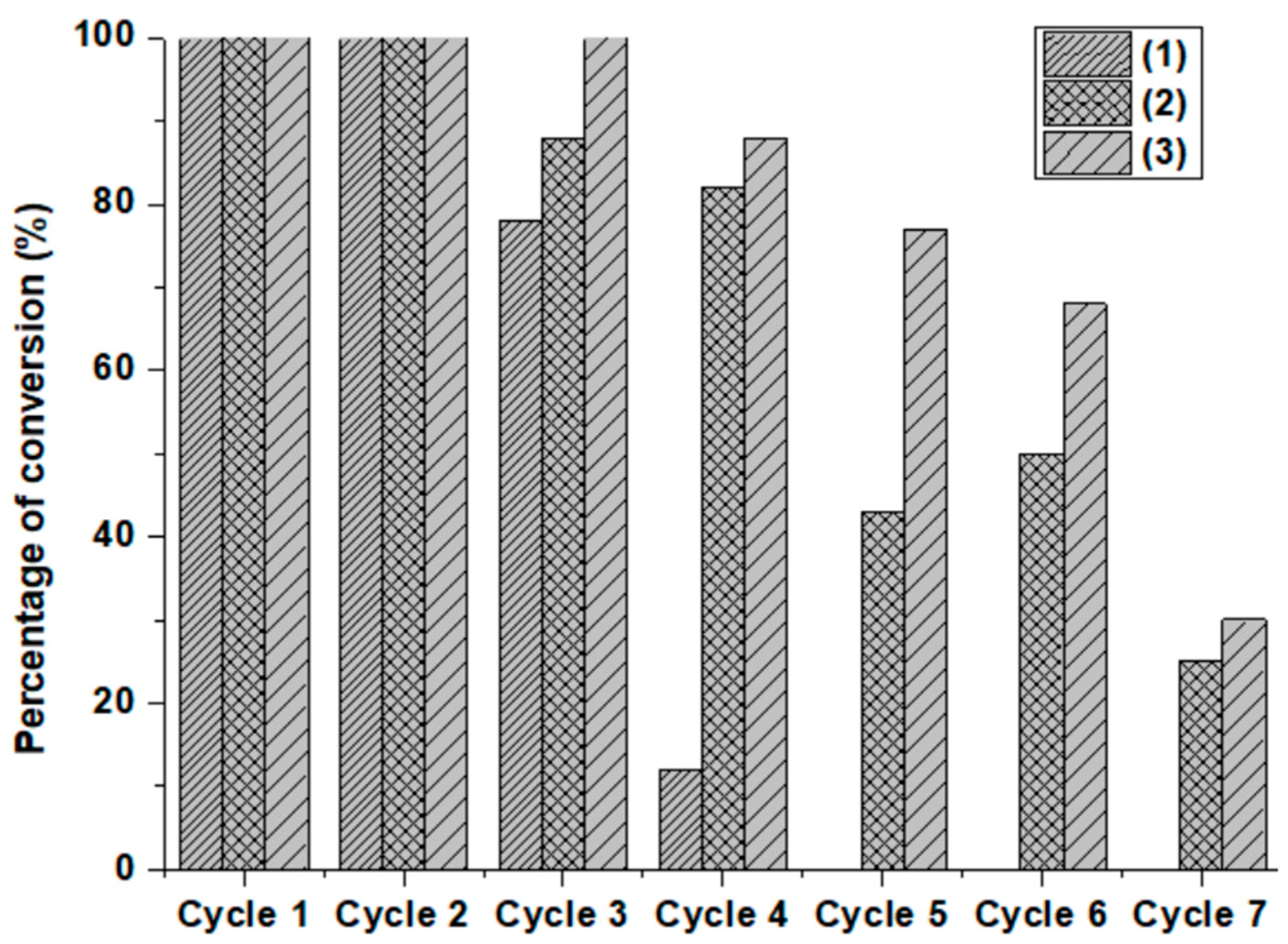
2.4. Deactivation and Regeneration of the Presented Composites

We found that after repeated cycles, and when the reaction became very slow, the re-addition of extra amounts of sodium borohydride restarted the catalytic reaction normally. It could be that some oxidized cobalt, as a side product from the reduction of 2,4-dinitrophenol, can be reduced again with the addition of extra NaBH4, and a new cycle starts. Co(0) in the catalysts (13) is the active site for the reduction of 2,4-DNP, since cobalt nanocolloids were found to be active efficient catalysts for p-nitrophenol reduction [50]. Furthermore, the presence of Co2O3 and CoCl2 on the surface of the catalyst can react with NaBH4 and form cobalt boride Co2B in situ. The latter can act as an intermediate catalyst in the generation of the hydrogen necessary for the reduction of 2,4-DNP [51,52]. Recent studies clearly indicated that the improved hydrolysis of NaBH4 by cobalt nanoparticles in N-doped carbon nanocomposites Co@NC, rather than producing the self-hydrolysis of NaBH4, can produce active hydrogen, which is responsible for the efficient reduction of 4-nitrophenol [30]. Calorimetric measurements suggest the ‘‘in situ’’ formation of a catalytically active CoxB phase through the ‘‘reduction’’ of an outer protective oxide layer of cobalt nanoparticles [39,43]. Finally, if some cobalt oxide is formed during the reaction, cobalt oxide-based material can still reduce nitrophenols in the presence of NaBH4 according to study [24].
The nanocatalyst (2) of a previous experiment, where six consecutive additions of 50 μL of DNP (4.4 × 10⁻³ M) were successfully reduced to 2,4-diaminophenol (Figure 14), was recovered by centrifugation at 12,000 rpm and washed with methanol and water several times to reactivate the catalyst. Due to the ferromagnetic properties of the catalyst, it can be separated from the reaction mixture and washed. Similarly, cyclic reductions were performed in a cell containing 3 mL of water by adding 50 µL of the fresh solution (1 M) of NaBH4 and 50 µL of 2,4-DNP (4.4 × 10⁻³ M) for each cycle. We were able to perform up to four new complete cycles of reduction, and the process then became slow and the reduction was not complete (Figure S7).
We conclude that the recovery and reactivation of the catalyst is successful by physical means, such as washing with solvents. Thus, the competition of accessibility to the active site due to physical adsorption of products and side products on the surface of catalyst is the major contributor to the deactivation mechanism [31]. Chemical deactivation is minor since no major change in the structure of catalyst was observed in SEM (Figure S8) of the used catalyst (1). In general, the morphology was not affected by the reaction condition. Some cobalt nanoparticles are still present, though a few were lost due to leaching from carbon support into the solution.
The new cobalt(0) nanoparticles show exceptional stability throughout the catalytic runs against leaching and sintering. Sample (2) retains its activity even at the sixth catalytic reuse before washing (Figure 14), and at the additional four new cycles after washing (Figure S7). This is attributed to the fact that cobalt nanoparticles are protected by graphitic shells and anchored onto graphitic supports, as indicated in the SEM Figures.

2.5. Effect of Adsorption of DNP on the Catalytic Activity of Nanocatalysts

Our materials are not powder-like. They consist of small silver/black metallic flakes (Figure S9). Thus, it is expected to be non-porous or to have very low porosity. The sintered catalyst materials we have obtained, though less porous, are more stable than others reported in the literature. The advantage of cobalt hierarchical carbon nanomaterials Co@HGC is that the cobalt–carbon constituents are held together in a robust way and resist leaching and degradation during the catalysis reaction.
Indeed, we have previously measured BET for similar materials prepared from similar conditions, but starting with Co2,2′-bipyCl2 instead of a [Co(phen)2Cl2] complex. It gave very-low and moderate BET surface areas of 3.4 m2/g. The porosity of materials improved when we repeated the synthesis using silica powder as support, and gave 97.8 m2/g [53].
We have performed adsorption experiments of DNP onto catalyst (3) by following the same experimental condition as used for catalysis but without adding sodium borohydride. The experimental capacity was only 6.4 mg/g (16.8% removal). The experiment was repeated with different concentrations of 2,4-DNP ranging from 7.67 mg/L to 29.3 mg/L in order to calculate the maximum capacity qmax mg/g. Figure S10 shows Langmuir’s adsorption isotherm plot for 2,4-DNP by catalyst (3). Where Ce (mg/L) is the remaining concentration of 2,4-DNP and qe (mg/g) is the experimental capacity. The Langmuir capacity qmax was found equal to 16.6 mg/g. We can infer that since the adsorption capacity is not high, the sample has low porosity.
A follow-up of the reactor catalytic reaction between 1.3 mg of catalyst (3) with 5.5 mg 2,4-DNP and 75 mg NaBH4 in 30 mL deionized water (Figure S11) indicates that the reaction proceeds at the surface of flakes with vigorous hydrogen gas evolution. This suggests that the catalyst, when reacting with NaBH4, promotes both hydrogen gas generation through the intermediate catalyst-formed Co2B as well as reductions of 2,4-DNP [30]. Both processes occurred at the surface of catalyst. Porosity of catalysts can improve the reaction because more 2,4-DNP and hydrogen can adsorb at surface of catalysts and therefore react together. But this is more necessary if we are using hydrogen gas from a gas cylinder at high pressure. The hydrogen gas has to dissolve and move towards the catalyst, adsorb onto it, and react with 2,4-DNP at the surface. In our situation (Figure S11), we can see that hydrogen is moving in the solution in an opposite direction, i.e., from surface of the catalyst towards the surface of the solution and evolving out of it, causing the inflation of wrapped paraffin paper.

3. Experimental Section

3.1. Preparation of Cobalt–Carbon Nanoparticles Catalyst Co@HGC (1), (2), and (3)

Preparation of (1)
[Co(phen)2Cl2]·1.5CH3CN [29] (0.2 g) and anthracene (0.064 g) were mixed in a crucible without a lid cover and placed inside a furnace under low pressure of nitrogen gas. Then, it was heated for 2 h to reach 600 °C. This was followed by pyrolysis at 600 °C for 8 h. Porous silver/black flakes were obtained with a yield of 0.05 g; Scheme 1.
Preparation of (2)
[Co(phen)2Cl2]·1.5CH3CN (0.2 g) and anthracene (0.064 g) were mixed in a crucible covered with a lid and placed in a furnace under low nitrogen gas pressure. Then, it was heated for two hours to reach 300 °C. The mixture was left for 2 h at 300 °C (intermediate stage). The heating was increased again for one hour to reach 600 °C. Finally, isothermal heat was used for 8 h at 600 °C. Flaky silver/black shiny foams (0.0737 g) were obtained after slow cooling; Scheme 1.
Preparation of (3)
[Co(phen)2Cl2]·1.5CH3CN (0.2 g) and anthracene (0.064 g) were mixed in a crucible with a cover lid and placed inside a nitrogen atmosphere furnace at low pressure. Two and a half hours of heating was used to reach 800 °C, then kept at 800 °C for 5 h. After cooling, 0.076 g of silver/black flakes were obtained; Scheme 1.

3.2. Characterization of Co@HGC

Raman spectra were recorded with a Jobin Yvon LabRAM HR Evolution Raman microscope, (HORIBA, Palaiseau, France); equipped with Syncerity scientific CCD Deep Cooled camera and an automated XY motorized stage. The line of the 633 nm laser was used as the source of excitation. Before the measurements were performed, the micro-Raman spectrometer was well-calibrated using 521 cm−1 Raman line of a single crystalline silicon (Si) wafer.
Powder X-ray diffraction (PXRD) measurements of Co@HGC samples were carried out using X’Pert PRO MP X-ray diffractometer (PANalytical, Almelo, Netherlands) consisting of a focusing elliptical mirror and a fast-high resolution detector (PIXCEL) employing a radiation source of Cu Kα in which λ equals 1.5418 Å. The 2θ range of diffractograms was recorded between 20° to 80° at a step size of 0.01° per minute.
Morphologies of the synthesized samples were characterized by field emission scanning electron microscope instrument (FE-SEM, JEOL JSM-76700F), (JEOL, Tokyo, Japan). All the samples were analyzed with acceleration voltage of 15 kV, working distance of 8 mm, and sample vacuum of 1 × 10⁻⁵ Pa.
HR-TEM images of samples were obtained using a Talos F200X Scanning/Transmission Electron Microscope (STEM) (Thermo Fischer, Waltham, MA, USA) with a lattice-fringe resolution of 0.14 nm at an accelerating voltage of 200 kV equipped with CETA 16M camera (Thermo Fischer, Waltham, MA, USA).
X-ray Photoelectron Spectroscopy (XPS). The measurements were carried out on GmbH high vacuum multi-technique surface analysis system (SPECS, Berlin, Germany). The XPS was implemented with a monochromatic Al Kα (hv = 1486.7 eV) as an excitation light source in which the steps, collection time, and pass energy were 0.1 eV, 0.5 s, and 20 eV, respectively. The photoelectrons being detected were at a 90° take-off angle. The spectra were referenced to the binding energy (BE) of the C 1s peaks (284.6 eV). The XPS data were fitted using the CasaXPS software.

3.3. Kinetic Studies

Kinetic procedure of the reducing catalytic activity: roughly 1 mg of nanocatalyst (1), (2), or (3) were dispersed in 5 mL of deionised water under sonication for 15 min. The dispersed mixture was used to record the baseline on the UV-Visible spectrophotometer before starting the catalytic activity measurements, in order to subtract the effect of the light scattering by the nanoparticles.
On the other hand, a fresh solution of 2,4-Dinitrophenol (DNP) was prepared by dissolving 11.7 mg of DNP in 25 mL of deionised water. A 0.18 M fresh-solution of sodium borohydride (NaBH4) was also prepared for the purpose of reduction.
A quantity of 3 mL of dispersed catalyst was introduced into a quartz cell (ℓ = 1 cm), followed by adding 100 µL of DNP solution and 50 µL of NaBH4 solution. Mixing of solution was achieved using an eye dropper. The evolution of hydrogen gas during the reaction also helped the mixing of the components of the mixture. The UV-2600 spectrophotometer (Shimadzu, Tokyo, Japan) was used to record the spectra range from 200 to 600 nm at defined times.

3.4. Successive Reduction of 2,4-DNP

Nanocatalyst (2) was selected for the successive reduction study in the quartz cell. Briefly, 50 µL of DNP solution (4.4 × 10⁻³ M) was added into a quartz cell containing 3 mL (0.2 g/L) of dispersed catalyst by sonication. This is followed by adding 50 µL of fresh solution of NaBH4 (1M). The rate constant was calculated from the decrease in intensity of the absorption peak at 358 nm (λmax of 2,4-DNP) over time for different experiments. At the end of each cycle of reduction, an additional 50 µL of DNP was added to the solution and the reduction process was monitored as in the previous cycle. After the sixth cycle the reduction started to slow and the process was stopped.

3.5. Reduction of 2,4-DNP Reduction under Sonication

A quantity of 1.3 mg of nanocatalyst (1), (2), or (3) was dispersed in 30 mL of deionised water under continuous sonication. For each cycle, 5.5 mg of DNP and 75 mg of NaBH4 were used, and the reduction was monitored using the UV-Visible spectrophotometer and the percentage of reduction for each cycle was calculated. The average time for completion of each cycle is around 30 min.

4. Conclusions

Novel cobalt hierarchical graphitic carbon nanoparticles Co@HGC (1), (2), and (3) were prepared by the simple pyrolysis of a cobalt phenanthroline chloride complex in the presence of carbon-source anthracene at different temperatures and heating times, under a nitrogen atmosphere. Samples (1) and (3) were prepared by heating at 600 °C and 800 °C, respectively, while (2) was prepared by heating at 600 °C, with an additional intermediate stage at 300 °C.
The in situ-prepared cobalt nanoparticles catalyze graphite formation at high temperatures of 600 °C and above. The nanocatalysts were characterized by SEM, EDX, TEM, Raman, XRD, and XPS. The analysis revealed the presence of cobalt and cobalt oxide species as well as graphitized carbon. The nanocatalysts contained cobalt nanoparticles of 3–20 nm in size. The produced hierarchical graphitic carbon provided a coverage shell, as well as a matrix of support for cobalt nanoparticles. This makes the catalyst robust and resists degradation during catalytic reactions.
The nanocatalysts were tested for the hydrogenation of 2,4-dinitrophenol. Catalyst (3), prepared at high temperatures of 800 °C, showed the highest catalytic conversion, which can be attributed to its higher content of graphitic structures and more uniformly dispersed cobalt–carbon nanoparticles compared to the other catalysts.
The apparent rate constants kapp (min−1) of 2,4-dinitrophenol reduction were 0.34 for (2), 0.17 for (3), 0.04 for (1), and 0.005 (no catalyst).
Nanocatalyst (1) demonstrated less catalytic activity. The cobalt nanoparticles of (1) are much more agglomerated than those of the two other nanomaterials (2) and (3). The catalysis experiment is simple and fast. It is performed at room temperature in water using self-generated hydrogen from the hydrolysis of sodium borohydride. The catalyst reduces 2,4-dinitrophenol to p-diamino phenol while enhancing hydrogen generation in the presence of sodium borohydride (possibly through a hydrogen mediator such as Co2B).
The catalyst can be regenerated and used for several cycles. These results should pave the road towards future discoveries of cheap and efficient metal–carbon nanocatalysts for different industrial applications.

Supplementary Materials

The following supporting information can be downloaded at: https://www.mdpi.com/article/10.3390/catal12010039/s1, Table S1: Effect of experimental conditions on the microscopic structure of the obtained cobalt carbon nanomaterials; Figure S1; SEM-EDX spectrum of catalysts (1), (2) and (3). Figure S2: TEM-EDX of nano-catalysts (1) and (3); Figure S3: (a) (b) and (c) XPS survey spectrum of nano-catalyst of (1), (2) and (3) respectively; Figure S4: Time-dependent UV-visible absorption spectrum for the reduction of DNP with NaBH4 in the presence of nano-catalyst (1); Figure S5: Time-dependent UV-visible absorption spectrum for the reduction of DNP with NaBH4 in the presence of nano-catalyst (3); Figure S6: Time-dependent UV-visible absorption spectrum for the reduction of DNP with NaBH4 in absence of catalyst; Figure S7: After regeneration of (2): complete reduction for new four successive cycles; Figure S8: SEM of the used catalyst (1); Figure S9: Image of cobalt hierarchical carbon nanomaterials Co@HGC catalyst (1), (2) and (3); Figure S10: Langmuir adsorption isotherm for 2,4-DNP by catalyst (3); Figure S11: Tracked observation of hydrogen gas generation during reduction experiment.

Author Contributions

H.H.H., supervised the work and wrote the manuscript; H.T., assisted in writing the manuscript; R.K.K., performed pyrolysis experiments; H.T. and R.K.K. performed catalysis experiments; S.G.H., performed nanomaterial analysis and characterizations; E.M.B. assisted in discussing and revising the paper. All authors have read and agreed to the published version of the manuscript.

Funding

This research was funded by Deanship of Scientific Research at King Faisal University; grant number 1811029 And the APC was also funded by 1811029 Deanship of Scientific Research at King Faisal University.

Data Availability Statement

Not applicable.

Acknowledgments

The authors acknowledge the Deanship of Scientific Research at King Faisal University, Saudi Arabia, for financial support under the Research Group (Grant No. 1811029).

Conflicts of Interest

There is no conflict to declare.

References

  1. Xie, L.; Wu, J.; Chen, C.; Zhang, C.; Wan, L.; Wang, J.; Kong, Q.; Lv, C.; Li, K.; Sun, G. A novel asymmetric supercapacitor with an activated carbon cathode and a reduced graphene oxide-cobalt oxide nanocomposite anode. J. Power Sources 2013, 242, 148–156. [Google Scholar] [CrossRef]
  2. Mei, J.; Liao, T.; Ayoko, G.A.; Bell, J.; Sun, Z. Cobalt oxide-based nanoarchitectures for electrochemical energy applications. Prog. Mater. Sci. 2019, 103, 596–677. [Google Scholar] [CrossRef]
  3. Lin, X.; Nie, Z.; Zhang, L.; Mei, S.; Chen, Y.; Zhang, B.; Zhuc, R.; Liu, Z. Nitrogen-doped carbon nanotubes encapsulate cobalt nanoparticles as efficient catalysts for aerobic and solvent-free selective oxidation of hydrocarbons. Green Chem. 2017, 19, 2164–2173. [Google Scholar] [CrossRef]
  4. Song, T.; Ren, P.; Duan, Y.; Wang, Z.; Chen, X.; Yang, Y. Cobalt Nanocomposites on N-Doped Hierarchical Porous Carbon for Highly Selective Formation of Anilines and Imines from Nitroarenes. Green Chem. 2018, 20, 4629–4637. [Google Scholar] [CrossRef]
  5. Zhu, W.; Ren, J.; Gu, X.; Azmat, M.U.; Lu, G.; Wang, Y. Synthesis of hermetically-sealed graphite-encapsulated metallic cobalt (alloy) core/shell nanostructures. Carbon 2011, 49, 1462–1472. [Google Scholar] [CrossRef]
  6. Hammud, H.H.; el Hamaoui, B.; Noubani, N.H.; Feng, X.; Wu, Z.S.; Müllen, K.; Ayub, K. Carbon-Cobalt Nanostructures as an Efficient Adsorbent of Malachite Green. Nanosci. Nanotechnol. Asia 2018, 8, 263–280. [Google Scholar] [CrossRef]
  7. Bethune, D.S.; Kiang, C.H.; de Vries, M.S.; Gorman, G.; Savoy, R.; Vazquez, J.; Beyers, R. Cobalt-catalysed growth of carbon nanotubes with single-atomic-layer walls. Nature 1993, 363, 605–607. [Google Scholar] [CrossRef]
  8. Nishide, D.; Kataura, H.; Suzuki, S.; Okubo, S.; Achiba, Y. Growth of single-wall carbon nanotubes from ethanol vapor on cobalt particles produced by pulsed laser vaporization. Chem. Phys. Lett. 2004, 392, 309–313. [Google Scholar] [CrossRef]
  9. Terrado, E.; Redrado, M.; Munoz, E.; Maser, W.K.; Benito, A.M.; Martinez, M.T. Carbon nanotube growth on cobalt-sprayed substrates by thermal CVD. Mat. Sci. Eng. C 2006, 26, 1185–1188. [Google Scholar] [CrossRef]
  10. Hamaoui, B.E.; Zhi, L.; Wu, J.; Li, J.; Lucas, N.T.; Tomović, Z.; Kolb, U.; Müllen, K. Solid-State Pyrolysis of Polyphenylene–Metal Complexes: A Facile Approach Toward Carbon Nanoparticles. Adv. Funct. Mater. 2007, 17, 1179–1187. [Google Scholar] [CrossRef]
  11. Hamaoui, B.E.; Zhi, L.; Wu, J.; Kolb, U.; Müllen, K. Uniform Carbon and Carbon/Cobalt Nanostructures by Solid-State Thermolysis of Polyphenylene Dendrimer/Cobalt Complexes. Adv. Mater. 2005, 17, 2957–2960. [Google Scholar] [CrossRef]
  12. Pereira, L.R.; Mondal, P.K.; Alves, M.S. Aromatic amines: Main sources, environmental impact and remediation. In Environmental Chemistry for a Sustainable World; Lichtfouse, E., Schwarzbauer, J., Robert, D., Eds.; Springer: Berlin, Germany, 2013. [Google Scholar] [CrossRef]
  13. Raja, R.; Golovko, V.B.; Thomas, J.M.; Berenguer-Murcia, A.; Zhou, W.; Xiee, S.; Johnsona, B.F.G. Highly efficient catalysts for the hydrogenation of nitro-substituted aromatics. Chem. Commun. 2005, 15, 2026–2028. [Google Scholar] [CrossRef]
  14. Corma, A.; Gonález-Arellano, C.; Iglesias, M.; Sánchez, F. Gold complexes as catalysts: Chemoselective hydrogenation of nitroarenes. Appl. Catal. A 2009, 356, 99–102. [Google Scholar] [CrossRef]
  15. Fu, Y.; Xu, P.; Huang, D.; Zeng, G.; Lai, C.; Qin, L.; Li, B.; He, J.; Yi, H.; Cheng, M.; et al. Au nanoparticles decorated on activated coke via a facile preparation for efficient catalytic reduction of nitrophenols and azo dyes. Appl. Surf. Sci. 2019, 473, 578–588. [Google Scholar] [CrossRef]
  16. Nasrollahzadeh, M.; Issaabadi, Z.; Sajadi, S.M. Green synthesis of the Ag/Al2O3 nanoparticles using Bryonia alba leaf extract and their catalytic application for the degradation of organic pollutants. J. Mater. Sci. Mater. Electron. 2019, 30, 3847–3859. [Google Scholar] [CrossRef]
  17. Das, R.; Sypu, V.S.; Paumo, H.K.; Bhaumik, M.; Maharaj, V.; Maity, A. Silver decorated magnetic nanocomposite (Fe3O4@PPy-MAA/Ag) as highly active catalyst towards reduction of 4-nitrophenol and toxic organic dyes. Appl. Catal. B Environ. 2019, 244, 546–558. [Google Scholar] [CrossRef]
  18. Makaudi, R.; Paumo, H.K.; Pone, B.K.; Katata-Seru, L. In Situ Stabilisation of Silver Nanoparticles at Chitosan-Functionalised Graphene Oxide for Reduction of 2,4-Dinitrophenol in Water. Polymers 2021, 13, 3800. [Google Scholar] [CrossRef]
  19. Dejmkova, H.; Stoica, A.I.; Barek, J.; Zima, J. Voltammetric and amperometric determination of 2,4-dinitrophenol metabolites. Talanta 2011, 85, 2594–2598. [Google Scholar] [CrossRef] [PubMed]
  20. Liu, Y.; Zhu, L.; Zhang, Y.; Tang, H. Electrochemical sensoring of 2,4-dinitrophenol by using composites of graphene oxide with surface molecular imprinted polymer. Sens. Actuators B 2012, 171–172, 1151–1158. [Google Scholar] [CrossRef]
  21. Jagadeesh, R.V.; Banerjee, D.; Arockiam, P.B.; Junge, H.; Junge, K.; Pohl, M.M.; Radnik, J.; Brückner, A.; Beller, M. Highly Selective Transfer Hydrogenation of Functionalysed Nitroarenes Using Cobalt-based Nanocatalysts. Green Chem. 2015, 17, 898–902. [Google Scholar] [CrossRef]
  22. Westerhaus, F.A.; Jagadeesh, R.V.; Wienho¨fer, G.; Pohl, M.; Radnik, J.; Surkus, A.; Rabeah, J.; Junge, K.; Junge, H.; Nielsen, M.; et al. Heterogenized cobalt oxide catalysts for nitroarene reduction by pyrolysis of molecularly defined complexes. Nat. Chem. 2013, 5, 537–543. [Google Scholar] [CrossRef] [PubMed]
  23. Yusran, Y.; Xu, D.; Fang, Q.; Zhang, D.; Qiu, S. MOF-derived Co@N-C nanocatalyst for catalytic reduction of 4-nitrophenol to 4-aminophenol. Microporous Mesoporous Mater. 2017, 241, 346–354. [Google Scholar] [CrossRef]
  24. Shultz, L.R.; McCullough, B.; Newsome, W.J.; Ali, H.; Shaw, T.E.; Davis, K.O.; Uribe-Romo, F.J.; Baudelet, M.; Jurca, T. A Combined Mechanochemical and Calcination, Route to Mixed Cobalt Oxides for the Selective Catalytic Reduction of Nitrophenols. Molecules 2020, 25, 89. [Google Scholar] [CrossRef] [Green Version]
  25. Naseem, K.; Begum, R.; Farooqi, Z.H.; Wu, W.; Irfan, A. Core-shell microgel stabilized silver nanoparticles for catalytic reduction of aryl nitro compounds. Appl. Organomet. Chem. 2020, 34, e5742. [Google Scholar] [CrossRef]
  26. Karakas, K.; Celebioglu, A.; Celebi, M.; Uyar, T.; Zahmakiran, M. Nickel nanoparticles decorated on electrospun polycaprolactone/chitosan nanofibers as flexible, highly active and reusable nanocatalyst in the reduction of nitrophenols under mildconditions. Appl. Catal. B Environ. 2017, 203, 549–562. [Google Scholar] [CrossRef]
  27. Gerelbaatar, K.; Tsogoo, A.; Dashzeveg, R.; Tsedev, N.; Ganbold, E. Reduction of 2,4-Dinitrophenol to 2,4-Diaminophenol Using AuNPs and AgNPs as Catalyst. Solid State Phenom. 2018, 271, 76–84. [Google Scholar] [CrossRef]
  28. Alotaibi, N.; Hammud, H.H.; Karnati, R.K.; Hussain, S.G.; Mazher, J.; Prakasam, T. Cobalt–carbon/silica nanocomposites prepared by pyrolysis of a cobalt 2,2’-bipyridine terephthalate complex for remediation of cationic dyes. RSC Adv. 2020, 10, 17660–17672. [Google Scholar] [CrossRef]
  29. Hazell, A.; McGinley, J.; McKenzie, C.J. Dichlorobis(1,10-phenanthrolineN,N′)-cobalt(II)-Acetonitrile (1/1.5). Acta Cryst. 1997, C53, 723–725. [Google Scholar]
  30. Xu, Y.; Shan, W.; Liang, X.; Gao, X.; Li, W.; Li, H.; Qiu, X. Cobalt Nanoparticles Encapsulated in Nitrogen-Doped Carbon Shells: Efficient and Stable Catalyst for Nitrobenzene Reduction. Ind. Eng. Chem. Res. 2020, 59, 4367–4376. [Google Scholar] [CrossRef]
  31. Li, M.; Chen, S.; Jiang, Q.; Chen, Q.; Wang, X.; Yan, Y.; Liu, J.; Lv, C.; Ding, W.; Guo, X. Origin of the Activity of Co−N−C Catalysts for Chemoselective Hydrogenation of Nitroarenes. ACS Catal. 2021, 11, 3026–3039. [Google Scholar] [CrossRef]
  32. Yin, X.; Liu, Q.; Ding, Y.; Chen, K.; Cai, P.; Wen, Z. Hierarchical Carbon/Metal Nanostructure with a Combination of 0D Nanoparticles, 1D Nanofibers, and 2D Nanosheets: An Efficient Bifunctional Catalyst for Zinc-Air Batteries. ChemElectroChem 2021, 8, 1107–1116. [Google Scholar] [CrossRef]
  33. Liu, Y.; Dong, P.; Li, M.; Wu, H.; Zhang, C.; Han, L.; Zhang, Y. Cobalt Nanoparticles Encapsulated in Nitrogen-Doped Carbon Nanotube as Bifunctional-Catalyst for Rechargeable Zn-Air Batteries. Front. Mater. 2019, 6, 85. [Google Scholar] [CrossRef]
  34. Wang, H.; Wang, Y.; Li, Y.; Lan, X.; Ali, B.; Wang, T. Highly efficient hydrogenation of nitroarenes by N-doped carbon supported cobalt single-atom catalyst in ethanol/water mixed solvent. ACS Appl. Mater. Interfaces 2020, 12, 34021–34031. [Google Scholar] [CrossRef]
  35. Sun, X.; Olivos-Suarez, A.I.; Osadchii, D.; Romero, M.J.V.; Kapteijn, F.; Gascon, J. Single Cobalt Sites in Mesoporous N-Doped Carbon Matrix for Selective Catalytic Hydrogenation of Nitroarenes. J. Catal. 2018, 357, 20–28. [Google Scholar] [CrossRef]
  36. Fei, H.; Dong, J.; Arellano-Jiménez, M.J.; Ye, G.; Kim, N.D.; Samuel, E.L.G.; Peng, Z.; Zhu, Z.; Qin, F.; Bao, J.; et al. Atomic cobalt on nitrogen-doped graphene for hydrogen generation. Nat. Commun. 2015, 6, 8668. [Google Scholar] [CrossRef] [PubMed]
  37. Zhang, Y.B.; Lau, S.P.; Huang, L.; Tay, B.K. Carbon nanotubes grown on cobalt-containing amorphous carbon composite films. Diam. Relat. Mater. 2006, 15, 171–175. [Google Scholar] [CrossRef]
  38. Xie, S.; Liu, Y.; Deng, J.; Yang, J.; Zhao, X.; Han, Z.; Zhang, K.; Dai, H. Insights into the active sites of ordered mesoporous cobalt oxide catalysts for the total oxidation of o-xylene. J. Catal. 2017, 352, 282–292. [Google Scholar] [CrossRef]
  39. Andrieux, J.; Swierczynski, D.; Laversenne, L.; Garron, A.; Bennici, S.; Goutaudier, C.; Miele, P.; Auroux, A.; Bonnetot, B. A multifactor study of catalyzed hydrolysis of solid NaBH4 on cobalt nanoparticles: Thermodynamics and kinetics. Int. J. Hydrog. Energy 2009, 34, 938–951. [Google Scholar] [CrossRef]
  40. Lee, D.; XunXia, Q.; Yun, J.M.; HoKim, K. High-performance cobalt carbonate hydroxide nano-dot/NiCo(CO3)(OH)2 electrode for asymmetric supercapacitors. Appl. Surf. Sci. 2018, 433, 16–26. [Google Scholar] [CrossRef]
  41. Shi, R.; Chen, G.; Ma, W.; Zhang, D.; Qiu, G.; Liu, X. Shape-controlled synthesis and characterization of cobalt oxides hollow spheres and octahedra. Dalton Trans. 2012, 41, 5981. [Google Scholar] [CrossRef]
  42. Tang, C.; Surkus, A.-E.; Chen, F.; Pohl, M.-M.; Agostini, G.; Schneider, M.; Junge, H.; Beller, M. A Stable Nanocobalt Catalyst with Highly Dispersed CoNx Active Sites for the Selective Dehydrogenation of Formic Acid. Angew. Chem. Int. Ed. 2017, 56, 16616–16620. [Google Scholar] [CrossRef]
  43. Nguyen-Huy, C.; Lee, J.; Seo, J.H.; Yang, E.; Lee, J.; Choi, K.; Lee, H.; Kim, J.H.; Lee, M.S.; Joo, S.H.; et al. Structure-Dependent Catalytic Properties of Mesoporous Cobalt Oxides in Furfural Hydrogenation. Appl. Catal. A Gen. 2019, 583, 117125. [Google Scholar] [CrossRef]
  44. Lesiak, B.; Kövér, L.; Tóth, J.; Zemek, J.; Jiricek, P.; Kromka, A.; Rangama, N. C sp2/sp3 hybridisations in carbon nanomaterials—XPS and (X)AES study. Appl. Surf. Sci. 2018, 452, 223–231. [Google Scholar] [CrossRef]
  45. Benkoula, S.; Sublemontier, O.; Patanen, M.; Nicolas, C.; Sirotti, F.; Naitabdi, A.; Gaie-Levrel, F.; Antonsson, E.; Aureau, D.; Ouf, F.; et al. Catalin Miron Water adsorption on TiO2 surfaces probed by soft X-ray spectroscopies: Bulk materials vs. isolated nanoparticles. Sci. Rep. 2015, 5, 10588. [Google Scholar] [CrossRef] [PubMed]
  46. Jia, R.; Chen, J.; Zhao, J.; Zheng, J.; Song, C.; Lia, L.; Zhu, Z. Synthesis of highly nitrogen-doped hollow carbon nanoparticles and their excellent electrocatalytic properties in dye-sensitized solar cell. J. Mater. Chem. 2010, 20, 10829–10834. [Google Scholar] [CrossRef]
  47. Sudhakar, P.; Soni, H. Catalytic reduction of Nitrophenols using silver nanoparticles-supported activated carbon derived from agro-waste. J. Environ. Chem. Eng. 2018, 6, 28–36. [Google Scholar] [CrossRef]
  48. Farooqi, Z.H.; Naseem, K.; Begum, R.; Ijaz, A. Catalytic reduction of 2-nitroaniline in aqueous medium using silver nanoparticles functionalized polymer microgels. J. Inorg. Organomet. Polym. Mater. 2015, 25, 1554–1568. [Google Scholar] [CrossRef]
  49. Oar-Arteta, L.; Wezendonk, T.; Sun, X.; Kapteijn, F.; Gascon, J. Metal organic frameworks as precursors for the manufacture of advanced catalytic materials. Mater. Chem. Front. 2017, 1, 1709. [Google Scholar] [CrossRef] [Green Version]
  50. Mondal, A.; Mondal, A.; Adhikary, B.; Mukherjee, D.K. Cobalt nanoparticles as reusable catalysts for reduction of 4-nitrophenol under mild conditions. Bull. Mater. Sci. 2017, 40, 321–328. [Google Scholar] [CrossRef]
  51. Delmas, J.; Laversenne, L.; Rougeaux, I.; Capron, P.; Garron, A.; Bennici, S.; Swierczynski, D.; Auroux, A. Improved hydrogen storage capacity through hydrolysis of solid NaBH4 catalyzed with cobalt boride. Int. J. Hydrog. Energy 2011, 36, 2145–2153. [Google Scholar] [CrossRef]
  52. Simagina, V.I.; Komova, O.V.; Ozerova, A.M.; Netskina, O.V.; Odegova, G.V.; Kellerman, D.G.; Bulavchenko, O.A.; Ishchenko, A.V. Cobalt oxide catalyst for hydrolysis of sodium borohydride and ammonia borane. Appl. Catal. A Gen. 2011, 394, 86–92. [Google Scholar] [CrossRef]
  53. Alotaibi, N.; Hammud, H.H.; al Otaibi, N.; Hussain, S.G. Thirumurugan Prakasam Novel cobalt–carbon@silica adsorbent. Sci. Rep. 2020, 10, 18652. [Google Scholar] [CrossRef] [PubMed]
Figure 1. SEM-descriptive projected figure (ad) redrawn to elaborate the effects of experimental conditions on the catalytic graphitization by cobalt nanoparticles (A), (1), (2), and (3) respectively. Scale unit is 1 micron meter for all.
Catalysts 12 00039 g001
Figure 2. Scanning electron microscopy SEM images (a), (b) and (c) of Co@HGC samples (1), (2), and (3) respectively.
Catalysts 12 00039 g002
Figure 3. (a) SEM-EDX mapping of (1); (b) SEM-EDX Mapping of (1)-acid. Zones for carbon, chlorine, and cobalt were shown. Agglomerated cobalt particles were not observed in (1)-acid (b).
Catalysts 12 00039 g003
Figure 4. (a), (b) and (c) high-resolution transmission electron microscopy (HRTEM) of Co@HGC samples (1), (2), and (3) respectively.
Catalysts 12 00039 g004aCatalysts 12 00039 g004b
Figure 5. Energy-dispersive X-ray TEM-EDX of Co@HGC (2).
Catalysts 12 00039 g005
Figure 6. Powder X-ray patterns (PXRD) of Co@HGC samples (1), (2), and (3).
Catalysts 12 00039 g006
Figure 7. Raman spectra of Co@HGC samples (1), (2), and (3).
Catalysts 12 00039 g007
Figure 8. XPS high-resolution spectra of Co 2p; (ac) for nanocatalysts (1), (2), and (3).
Catalysts 12 00039 g008
Figure 9. XPS high-resolution spectra of C (1s); (ac) for nanocatalysts (1), (2), and (3).
Catalysts 12 00039 g009
Figure 10. XPS high-resolution spectra of O (1s); (ac) for nanocatalysts (1), (2), and (3).
Catalysts 12 00039 g010
Figure 11. XPS high-resolution spectra of N (1s); (ac) for nanocatalysts (1), (2), and (3).
Catalysts 12 00039 g011
Figure 12. (a) Time-dependent UV-visible absorption spectrum for the reduction of DNP with NaBH4 in the presence of nanocatalyst (2): first 4 min; solvent: water; [DNP] = 8.5 × 10⁻⁵ M; [NaBH4] = 0.003 M; ℓ = 1 cm; T = 25 °C; 0.18 mg/mL of catalyst was used. (b) Time-dependent UV-visible absorption spectrum for the reduction of DNP with NaBH4 in the presence of nanocatalyst (2): from 5 to 13 min; solvent: water; [DNP] = 8.5 × 10⁻⁵ M; [NaBH4] = 0.003 M; ℓ = 1 cm; T = 25 °C; 0.18 mg/mL of catalyst was used.
Catalysts 12 00039 g012
Figure 13. Comparison of the kinetic plot of DNP reductions in absence and presence of the different nanocatalysts. Solvent: water; [DNP] = 8.5 × 10⁻⁵ M; [NaBH4] = 0.003 M; ℓ = 1 cm; T = 25 °C; 0.18 mg/mL of catalyst was used.
Catalysts 12 00039 g013
Figure 14. Cyclic catalytic reduction of DNP in quartz cell in presence of nanocatalyst (2)—sixth add. Solvent: water; [NaBH4] = 0.017 M; l = 1cm; T = 25 °C; 0.2 mg/mL of catalyst. A quantity of 50 µL of 4.4 × 10⁻³ M of DNP is added in the cuvette in each cycle. The inset image shows the linear increase of absorbance at 300 nm with the number of cycles.
Catalysts 12 00039 g014
Figure 15. Cyclic catalytic reduction of DNP in a flask containing 1.3 mg of nanocatalyst and 30 mL of water. Quantities of 5.5 mg of DNP and 75 mg of NaBH4 were added each cycle. Average time for the cycle is 30 min.
Catalysts 12 00039 g015
Scheme 1. Preparation of cobalt–carbon nanoparticles Co@HGC (1), (2), and (3).
Catalysts 12 00039 sch001
Publisher’s Note: MDPI stays neutral with regard to jurisdictional claims in published maps and institutional affiliations.

