Article

Pt-Mo/C, Pt-Fe/C and Pt-Mo-Sn/C Nanocatalysts Derived from Cluster Compounds for Proton Exchange Membrane Fuel Cells

by
Sergey S. Shapovalov
1,2,
Natalia A. Mayorova
3,
Alexander D. Modestov
3,*,
Andrei A. Shiryaev
3,
Alexander V. Egorov
4 and
Vitali A. Grinberg
3
1
Kurnakov Institute of General and Inorganic Chemistry, Russian Academy of Sciences, Leninsky Prospekt 31, 119991 Moscow, Russia
2
National Research University Higher School of Economics, Vavilova Street 7, 117312 Moscow, Russia
3
Frumkin Institute of Physical Chemistry and Electrochemistry, Russian Academy of Sciences, Leninsky Prospekt 31, Building 4, 119071 Moscow, Russia
4
Department of Chemistry Leninskie Gory, Lomonosov Moscow State University, 1 Building 3, 119991 Moscow, Russia
*
Author to whom correspondence should be addressed.
Catalysts 2022, 12(3), 255; https://doi.org/10.3390/catal12030255
Submission received: 25 January 2022 / Revised: 19 February 2022 / Accepted: 22 February 2022 / Published: 24 February 2022

Abstract

:
Nanosized bimetallic PtMo, PtFe and trimetallic PtMoSn catalysts deposited on highly dispersed carbon black Vulcan XC-72 were synthesized from the cluster complex compounds PtCl(P(C6H5)3)(C3H2N2(CH3)2)Mo(C5H4CH3)(CO)3, Pt(P(C6H5)3)(C3N2H2(CH3)2)Fe(CO)3(COC6H5C2C6H5), and PtCl(P(C6H5)3)(C3N2H2(CH3)2)C5H4CH3Mo(CO)3SnCl2, respectively. Structural characteristics of these catalysts were studied using X-ray diffraction (XRD), microprobe energy dispersive spectroscopy (EDX), and transmission electron microscopy (TEM). The synthesized catalysts were tested in aqueous 0.5 M H2SO4 in a three-electrode electrochemical cells and in single fuel cells. Electrocatalytic activity of PtMo/C and PtFe/C in the oxygen reduction reaction (ORR) and the activity of PtMoSn/C in electrochemical oxidation of ethanol were evaluated. It was shown that specific characteristics of the synthesized catalysts are 1.5–2 times higher than those of a commercial Pt(20%)/C catalyst. The results of experiments indicate that PtFe/C, PtMo/C, and PtMoSn/C catalysts prepared from the corresponding complex precursors can be regarded as promising candidates for application in fuel cells due to their high specific activity.

1. Introduction

The proton exchange membrane fuel cell (PEMFC) is an efficient instrument to convert the chemical energy of fuels into electric power [1]. Certain organic substances are considered to be very promising fuels for electrochemical energy conversion. These substances can be oxidized electrochemically even at room temperature. Among these fuels, methanol and ethanol have received particular attention due to the fact that they are less polluting to the environment and can be efficiently used in electrochemical energy conversion systems [2,3]. Direct ethanol fuel cells (DEFCs) are an attractive option for power generation as ethanol offers higher theoretical energy density (8.0 kWh kg−1) compared to methanol (6.1 kWh kg−1) and is less toxic [4]. In addition, ethanol can be easily produced by fermentation of biomass [5,6]. However, the slow kinetics of the ethanol electrooxidation reaction (EOR) on Pt anode catalysts reduces the overall performance of the DEFC system and hampers its commercialization [7]. Considerable efforts were applied to develop alternative anode electrocatalysts that offer higher catalytic activity while lowering the cost. For example, nanoparticle alloys of Pt with other elements such as Ti, Mo, Ru, Rh, Pd, Sn, W and Ce were synthesized and tested, and among them, Sn has shown the best promoting effect on EOR [8,9,10,11]. Nevertheless, it is still an ongoing task to further improve the performance of the Pt–Sn anode catalysts to enable commercialization of DEFCs.
Development of platinum-based anode catalysts with high catalytic activity in alcohol oxidation reactions [12] and of alcohol-tolerant cathode catalysts is an urgent task. This problem partly comes down to catalysts that oxidize CO at an acceptable rate with significant reduction in overvoltage. Nanoparticles of platinum alloys with Ru, Mo, Sn, W, and Rh are often used to increase the catalytic activity of platinum in hydrogen electrooxidation when CO containing hydrogen fuel is used [13,14,15,16].
In the last decades, synthesis of various catalysts, including Pt alloys, via heterometallic cluster compounds is becoming increasingly popular. Some recent review articles are given in references [17,18,19,20,21,22]. It should be noted that nanoalloys, in general, find application in a variety of technologies, ranging from catalytic converters in automobiles [23] to optoelectronic [24], magnetic [25], and even biomedical devices [26].
Previously, we synthesized a number of bi- and trimetallic alloy nanoparticle catalysts using corresponding heterometallic clusters. In a heterometallic cluster, atoms of platinum and other metal(s) are surrounded by organic groups and are bonded to each other either directly or via bridge groups in a strict stoichiometric ratio [17,18,19,20,21,22,27,28,29,30]. After deposition of a cluster precursor on a carbon support, the resulting intermediate material is subjected to pyrolysis. During thermal decomposition, all organic groups are removed, leaving a mixed-metal skeleton of a predetermined composition on the carbon support. As a result, reproducible, stable and highly active catalysts are obtained [29,30,31,32].
In the present work, we report further development of this approach for synthesis of bimetallic platinum-iron and platinum-molybdenum electrocatalysts, and also of a ternary Pt-Mo-Sn catalyst. Catalytic properties of the synthesized nano alloys are evaluated by cyclic voltammetry (CV), COad stripping voltammetry, chronoamperometry in a conventional electrochemical cell with aqueous electrolytes and in a membrane electrode assembly (MEA) of a single hydrogen-air PEMFC.

2. Results and Discussion

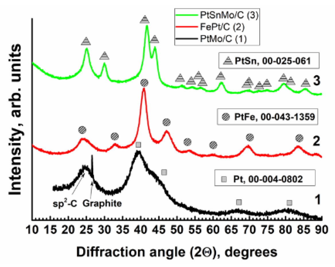
2.1. XRD, TEM and X-ray Fluorescence Studies

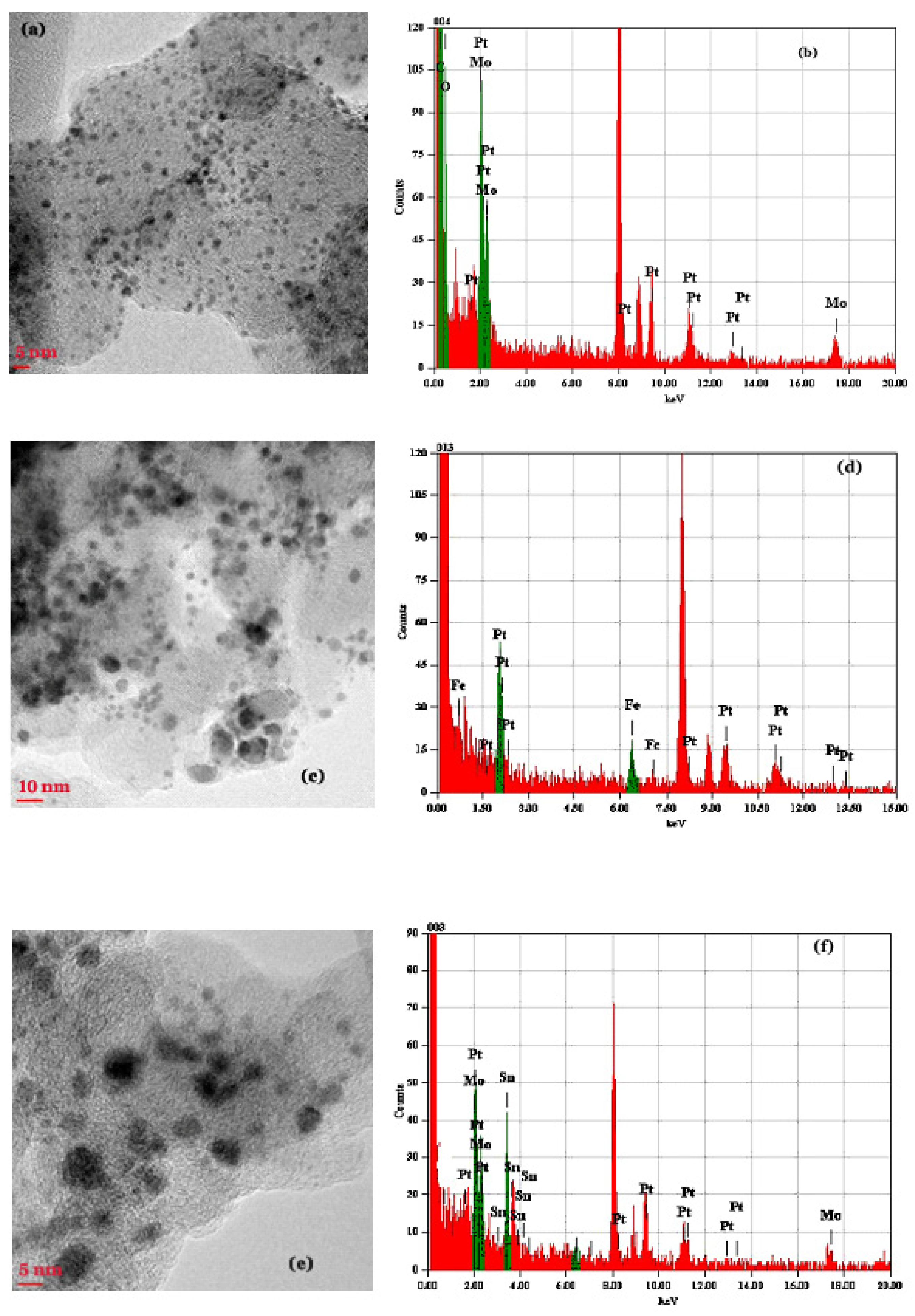
2.1.1. The PtMo/C Catalyst

According to the X-ray Fluorescence (XRF) spectroscopy measurements, Pt to Mo ratio in the sample is ~40/60 (at%). Note that due to small effective thickness of the carbon-based powder layer on the sample holder, the results of the performed Energy-dispersive X-ray (EDX) analysis are semiquantitative. The X-ray diffraction (XRD) pattern of the sample, shown in Figure 1, curve (1), reveals broad peaks from disordered sp2 (graphitic) carbon at 2θ~26° with several peaks, which could be assigned to nanocrystalline Pt, Mo, or their alloys. From the Scherrer formula, the crystallite size of a phase giving rise to the later reflections is 2.5–3.1 nm. Unfortunately, a very large breadth of the reflections precludes reliable identification of the alloy phase(s), since too many phases from the Mo–Pt diagram may fit the experimental pattern.
According to TEM images of PtMo/C, Figure 2a, the catalyst consists of roughly spherical carbon nanoparticles 20–30 nm in diameter, decorated by smaller particles with high Z-contrast. High-resolution Transmission Electron Microscopy (TEM) image shows that these small nanoparticles contain only platinum and molybdenum (C, O and Cu originate from the carbon support and copper grid) with a Pt/Mo ratio in the range 0.65–0.77. However, in some particles, Mo is less abundant. The median size of the metal particles is 2.2 ± 0.5 nm, which is close to the sizes determined by XRD measurements. Despite clearly observed lattice fringes, electron diffraction also fails in precise determination of the phase, Figure 2b.
Taken together, the results of TEM and XRD studies suggest that the applied synthesis technique produced Pt-Mo crystalline nanoparticles with rather narrow size distribution (~2.2 nm), but composition of these nanoparticles, apparently, varies. We cannot exclude the possibility of the coexistence of several populations of compositionally different particles of close diameter.

2.1.2. The PtFe/C Catalyst

X-ray diffraction pattern of this catalyst, shown in Figure 1, curve (2), corresponds to the tetragonal FePt phase. Crystallite size estimated using a Williamson–Hall plot is 6 ± 3 nm. The reason for large dispersion becomes clear from the TEM image, Figure 2c, which shows the presence of particles with distinctly different sizes: relatively large particles with a diameter ranging from 6 nm up to 20–30 nm and numerous smaller grains of 2–3 nm size. EDX analysis, Figure 2d, suggests that besides grains of the tetragonal FePt, some of the nanoparticles represent Fe-based, and, in contrast, Pt-based alloys. According to data of XRF spectroscopy for this sample, the Pt:Fe atomic ratio is 49:51 (at%), i.e., very close to the targeted one.

2.1.3. The PtMoSn/C Catalyst

X-ray diffraction pattern of this catalyst, Figure 1, curve (3), corresponds to hexagonal lattice of PtSn. At the same time, EDX analysis, Figure 2f, indicates the presence of significant amounts of Mo. Average composition of the sample (ignoring carbon) is approximately Mo:Sn:Pt = 37:38:25. XRF analysis of the samples of similar compositions in the light matrix (carbon) is complicated by a very high extinction length of Sn radiation and, thus, subject to bias. However, the quoted composition implies the presence of PtSn with significant admixture of Mo. Diffraction peaks pertinent to Molybdenum phase are missing in Figure 2f. Mo, apparently, is present as a solid solution in the PtSn phase. TEM image of the sample, Figure 2e, indicates the presence of small (2–3 nm) and larger metal alloy grains in the catalyst powder.
As follows from the results of structural studies, Mo concentration in PtMo/C catalyst and Sn and Mo concentrations in PtMoSn/C catalyst are somewhat higher than that in the corresponding complex precursors used for the catalyst preparation. The enrichment of the catalysts by these elements might be caused by Sn and Mo diffusion from the bulk of the catalyst particle to its surface layer during pyrolysis. A similar phenomenon of surface layer enrichment with less noble components was observed earlier for alloys dispersed on carbon black [33,34].

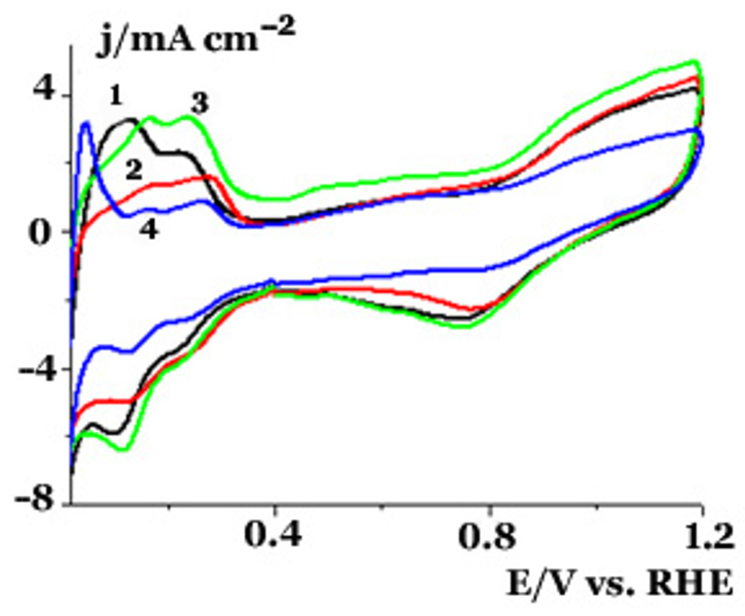
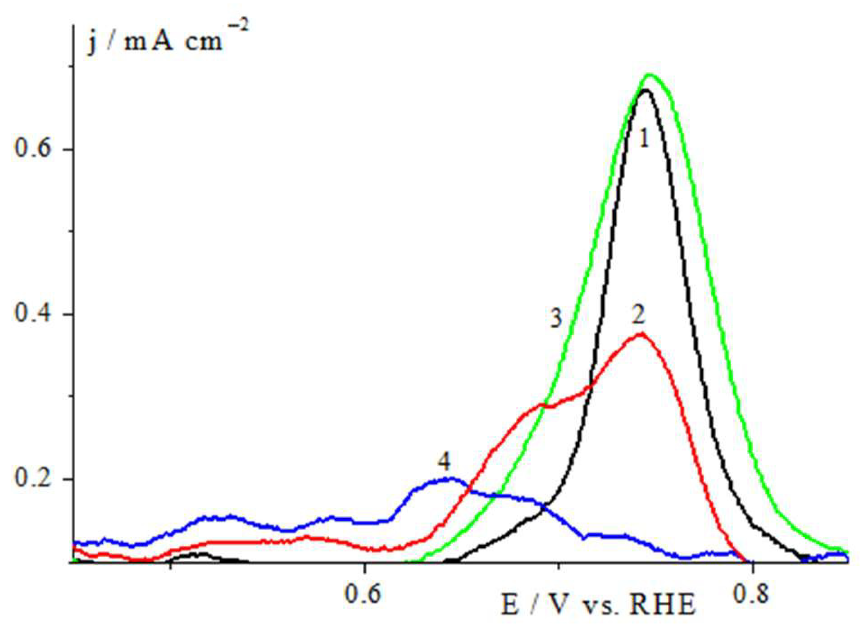
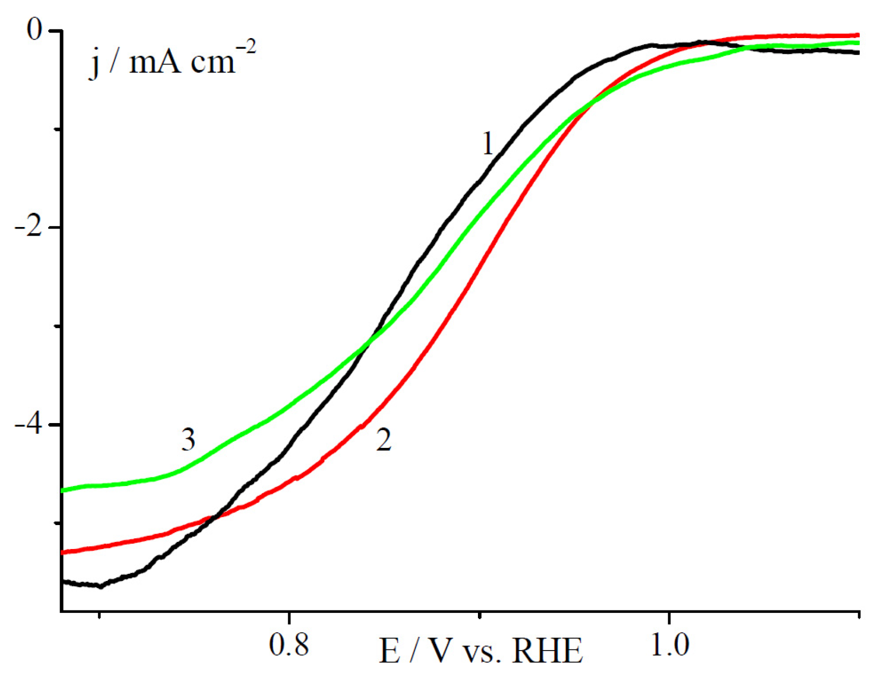
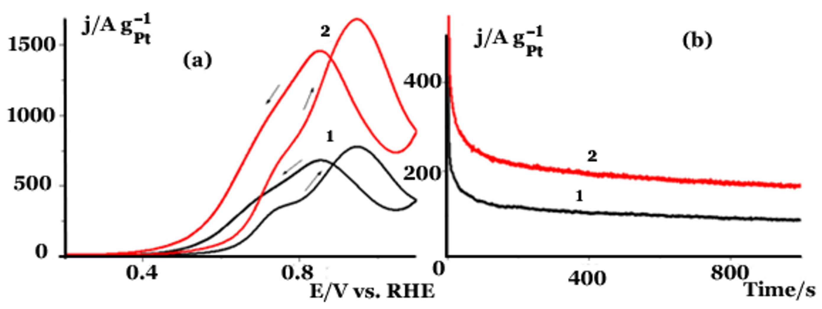
2.2. Electrochemical Studies in a Three Electrode Electrochemical Cell

Figure 3 shows cyclic voltammograms (CVs) recorded with a glassy carbon disk electrode coated by thin layer of PtFe/C, PtMo/C, PtMoSn/C, or commercial Pt/C catalyst in argon purged 0.5 M H2SO4. Measurements were performed at room temperature at a potential scan rate of 0.05 V s−1. These voltammetry curves enable comparison of the electrochemical surface characteristics of the catalysts. The voltammograms are of a similar shape for all catalysts, and show rather well-defined hydrogen adsortion/desorption peaks characteristic for polycrystalline Pt surface. For the PtMo/C catalyst, however, a noticeable increase in the double layer capacitance is observed (curve 3 in Figure 3) that may be ascribed to the formation of oxygenated molybdenum species on the surface of PtMo alloys (in similarity to PtRu catalyst [35]). An additional peak observed at 0.4–0.5 V is most likely due to the redox reaction Mo(VI) ↔ Mo(IV) [36,37]. The latter may have its effect on the stability of the PtMo/C catalyst.
The values of electrochemically active surface area (ECSA) obtained from the hydrogen adsorption/desorption charge in the 0.05–0.35 V potential range (SH) correspond to 98.5, 111.6, 146, and 139 m2gPt−1 for Pt/C, PtFe/C, PtMo/C, and PtMoSn/C, respectively. The highest ECSA for PtMo/C among the prepared samples is in agreement with the smallest particle size as measured by TEM (2.2 nm). Somewhat lower ECSA of PtMoSn/C in comparison to that of PtMo/C may imply surface segregation of Sn component in the ternary nanoparticles, resulting in the partial blockage of the Pt surface sites.
A positive shift of platinum oxides reduction potential at the PtFe/C catalyst (Figure 3, curve 2), that was observed for a number of Pt alloy catalysts (in particular, the ordered PtFe alloy [38], cluster complex-derived PtZn/C [30], and PtFe/C [32]), is assumed to indicate a change in the Pt–O bond strength and may result in a higher catalytic activity of the obtained PtFe/C catalyst as compared to the commercial Pt/C. Besides, the presence of the second metal in a platinum alloy also affects the Pt–CO bond and results in a negative shift of the COad oxidation potential, which was reported for the ordered fct-PtFe/C [39] and the complex-derived PtZn/C, PtCo/C and PtFe/C catalysts [30,32]. Therefore, carbon monoxide oxidation at the prepared cluster-derived catalysts was studied and compared to that at the commercial Pt/C catalyst.
Figure 4 shows the COad stripping voltammograms recorded at the commercial Pt/C and the prepared PtFe/C, PtMo/C, and PtMoSn/C in the potential range 0.2–1.0 V. According to Figure 4, COad stripping curves for all of the prepared catalysts are characterized by a lower CO oxidation onset potential in comparison to Pt/C. The curve of the COad stripping from the ternary PtMoSn/C catalyst reveals multiple peaks and the lowest onset potential (curve 4 in Figure 4), which may be related to the redox reactions of Mo and Sn resulting in formation of oxygenated species on Mo and Sn sites. According to the bifunctional mechanism, these oxygenated species assist the removal of COad at lower potentials [37].
The catalytic activity of the prepared PtFe/C and PtMo/C catalysts in the reaction of the oxygen reduction was compared to that of the commercial Pt/C using the thin layer rotating disk electrode (RDE) technique. Cyclic voltammograms were recorded in an oxygen saturated 0.5 M H2SO4, at atmospheric pressure and room temperature, in the potential range 0.3–1.1 V at a scan rate of 0.005 V s−1. Voltammetry curves of oxygen reduction at these three catalysts recorded at the RDE rotation rate 2500 rpm are shown in Figure 5 (the oxygen mass-transport limited potential region not shown). As can be seen from Figure 5, the prepared binary catalysts exhibit a ~15–30 mV positive shift of both oxygen reduction reaction (ORR) onset and half-wave potential compared to curves recorded with the Pt/C catalyst, thus indicating an enhanced catalytic activity of the alloy catalysts in the ORR. Such effect of the second metal presence is supposed to be due to modification of the electronic band structure of Pt resulting in reduction in the binding strength of intermediate species on Pt.
Current density and mass specific activity, both measured at E = 0.9 V (jO20.9 V), calculated from the ORR voltammetry curve for PtFe/C, reach 2.4 mA cm−2 and 108.3 mA mgPt−1, respectively. These values are higher than those measured with commercial Pt/C catalyst 1.55 mA cm−2 and 54.3 mA mgPt−1, respectively. Similar difference is observed in the values of surface specific current densities (0.097 mA cmecsa−2 and 0.055 mA cmecsa−2 for the PtFe/C and Pt/C, correspondingly), which is another evidence of a higher ORR activity of the PtFe/C catalyst, prepared from the corresponding complex precursor, in comparison with a commercial Pt/C.
Although current density and mass specific activity at E = 0.9 V for the PtMo/C catalyst (1.85 mA cm−2 and 86.3 mA mgPt−1, respectively) are higher than those of Pt/C, its surface specific activity is close to that of Pt/C (0.058 mA cmecsa−2 and 0.055 mA cmecsa−2, correspondingly). Therefore, the observed enhancement of PtMo/C activity in ORR is mostly due to its higher ECSA value resulting from smaller size of this catalyst particles. After the experiments described above, the catalyst film was removed from the surface of the working electrode using adhesive tape, and its composition was studied by XRF spectroscopy. Only Fe and Pt were observed in the PtFe/C sample, and despite sample-dependent variations of absolute values of intensity, the ratio Fe:Pt was constant within measurement error and equal to 47:53, which is close to the components ratio determined in the as-prepared catalyst. Some excess of molybdenum in the surface layer of the PtMo/C sample, noted for the as-prepared catalyst, was not found in the same catalyst examined after voltammetry testing in an acidic electrolyte (Pt:Mo = 51:49), i.e., the ratio of metal components was practically the same as the targeted one. It can be assumed that, as a result of the electrochemical treatment of the prepared bimetallic catalysts, the structure of a core-shell type is formed, where platinum atoms predominate in the shell. Results of XRF analysis of the catalysts are given in the Table S1 in Supplementary Data file.
It is worth mentioning that the data on the PtFe/C activity in ORR, obtained in the present work, are qualitatively and quantitatively in accordance with the results reported earlier for the PtFe/C catalyst derived from the heterometallic platinum-iron carboxylate complex precursor [PtFe(OAc)4]2O⋅4CH2Cl2 and studied in aqueous acid electrolyte both in a standard electrochemical cell and in a membrane electrode assembly of the single hydrogen-air fuel cell [32]. The reported data of XRD and XRF studies of this catalyst before and after the tests indicated the absence of changes in the phase composition and the ratio of metal components, which is consistent with the data of the present study. Thus, it can be concluded that the procedure applied for the preparation of supported catalysts, derived from complex cluster precursors, allows to synthesize active catalysts with predetermined compositions and reproducible characteristics, regardless of the precursor synthesis route used.
Catalytic activity of the prepared ternary catalyst PtMoSn/C in the reaction of ethanol oxidation was compared to that of the commercial Pt/C by CV measurements in 0.5 M H2SO4–1 M ethanol electrolyte in the potential range 0.2–1.1 V at a scan rate of 0.005 V s. Figure 6a shows the cyclic voltammograms of the ethanol oxidation at the PtMoSn/C and Pt/C catalysts normalized per mass of Pt at the electrodes. As can be seen from Figure 6, the ternary PtSnMo/C catalyst exhibits lower onset potential and an almost twice as high oxidation current over the entire potential range of the test.
In Figure 6b, the quasi-stationary activities of PtMoSn/C and Pt/C catalysts in EOR are compared at 0.6 V (jC2H5OH 0.6 V). Both samples demonstrate similar rates of current decay; however, the ethanol oxidation current at PtMoSn/C catalyst is roughly twice as high than that at Pt/C catalyst. The chronoamperometry measurements revealed that mass specific EOR currents at the prepared ternary catalyst are also twice as high than those at the commercial Pt/C catalyst, and 1.5 times higher than currents reported by Lee and coworkers for PtSnMo0.6/C synthesized by a polyol reduction method [37]. The mechanism of the EOR promotion at ternary PtMoSn alloys is still under discussion, the bifunctional effect of Sn and Mo and hydrogen spillover effect of Mo being considered [40,41,42].
The results of experiments performed in aqueous 0.5 M H2SO4 are summarized in Table 1. The results indicate that PtFe/C, PtMo/C, and PtMoSn/C catalysts prepared from the corresponding complex precursors can be regarded as promising candidates for application in fuel cells due to their higher specific activity in the reactions of the oxygen reduction and ethanol oxidation.

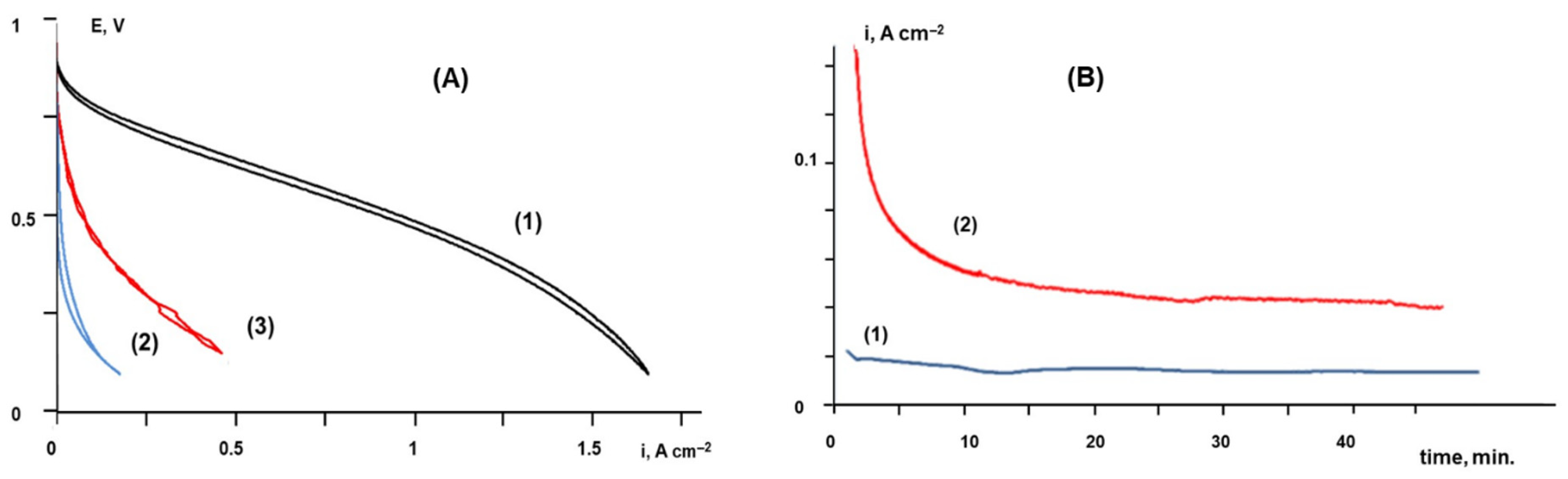
2.3. Tests of Membrane Electrode Assemblies

Figure 7a shows performance of two MEAs containing either Pt/C or PtMo/C in the anode catalyst layer. The cell, fuel and oxidant humidifiers were kept at the same temperature of 65 °C. Fuel flow rate (H2 or H2 + 40 ppm CO) was 400 mL per min. It corresponds to hydrogen supply stoichiometry of at least 7. According to the current ISO international standard, the maximum allowable limit of CO in hydrogen used in PEMFCs of road vehicles is only 0.2 ppm [43]. We used substantially higher CO concentration in order to obtain reproducible results in a relatively short experiment (only few hours). In the experiments with high fuel flow rates and high CO concentration, oxidation of hydrogen and CO adsorption at the anode catalyst layer do not cause significant change of fuel composition along its path in the test cell. At least three consecutive i-V curves were recorded to ensure reproducibility of the measurements. A 1 mV s−1 voltage scan rate was applied in both directions of the voltage change. The hydrogen oxidation performance curve of the MEA with the PtMo/C catalyst was close to a curve measured with thePt/C anode catalyst (curve 1 in Figure 7). Addition of 40 ppm CO to hydrogen fuel resulted in drastic decline of performance of both MEAs either with Pt/C (curve 2) or PtMo/C (curve 3) hydrogen oxidation catalysts. However, for particular CO concentrations, an actual decrease of the cell steady state voltage depends on current density, Pt loading at the anode, fuel supply rate, and humidification level [44]. In our experiments, due to the presence of 40 ppm CO in hydrogen, the cell voltage loss at i = 0.2 A cm−2 was ~0.65 V and ~0.4 V for Pt/C and PtMo/C catalysts, respectively.
To study polarization of the anode, experiments in a hydrogen pump mode were performed. In these experiments, pure hydrogen flow at the rate 50 milliliter per minute (mlpm) was supplied to the counter electrode of the MEA. Transients of the anode current density recorded when the anode potential was step changed from open circuit voltage (Eoc~0 V) to 0.5 V are shown in Figure 7b. The cell, gas, and humidifiers were kept at the same temperature 65 °C. Due to the negligible polarization of proton reduction at Pt/C catalyst, potential of the counter electrode flushed with pure hydrogen remains virtually constant. As can be seen from Figure 7b, at a constant potential of the hydrogen oxidation electrode (E = 0.5 V vs. RHE), current density reaches a steady value in ~10 min. Hydrogen oxidation rate at the PtMo/C catalyst was found to be higher than that at the Pt/C catalyst roughly by a factor of 3.

3. Materials and Methods

3.1. Preparation of Bimetallic PtMo/C, PtFe/C and Ternary PtMoSn/C Catalysts

Bimetallic and trimetallic complex compounds were synthesized in the laboratory of clusters in the Kurnakov Institute of General and Inorganic Chemistry, RAS. The synthesized complexes were used as precursors in preparation of platinum-molybdenum, platinum-iron and platinum-molybdenum-tin catalysts supported on Vulcan XC-72 carbon black. Three catalyst samples, namely PtMo/C, PtMoSn/C and PtFe/C, were prepared from the synthesized initial precursors PtCl(P(C6H5)3)(C3H2N2(CH3)2)Mo(C5H4CH3)(CO)3 (I), PtCl(P(C6H5)3)(C3N2H2(CH3)2)C5H4CH3Mo(CO)3SnCl2 (II) and Pt(P(C6H5)3)(C3N2H2(CH3)2)Fe(CO)3(COC6H5C2C6H5) (III), respectively. At the first step of the catalyst preparation, a highly dispersed Vulcan XC-72 carbon black was ultrasonicated in dichloromethane for 30 min. A solution of the precursors (I), (II) and (III) in dichloromethane was added to the suspension dropwise followed by an additional sonication and drying in vacuum at 100 °C. The solid residue was heated in a quartz tube at 450 °C in hydrogen atmosphere (1 bar) for 45 min. After cooling to room temperature, hydrogen was replaced by high-purity argon. The prepared catalysts contained 30 wt % metal and 70 wt % carbon black. According to results of XRF studies, Pt:Mo and Pt:Fe atomic ratio in the resulting binary alloys was close to 0.41:0.59 and 0.5:0.5, correspondingly. The atomic ratio Pt:Mo:Sn in the ternary alloy was close to 0.26:0.37:0.38.

3.2. Material Characterization

Phase composition of the prepared catalyst samples was studied by X-ray diffraction (XRD) using an Empyrean X-ray diffractometer (Panalytical BV). Ni-filtered Cu-Kα-radiation was employed; the samples were studied in Bragg–Brentano geometry. Transmission electron microscopy (TEM) was performed using a JEOL-2100F microscope operated at 200 kV. The powder was sonicated in ethanol, then drops of the suspension were dried on TEM copper grids. Low-tack adhesive tape (Scotch® 928, 3 M, Amazon, Koblenz, Germany) was used to fix the 400 mesh TEM grids (01754-F, Ted Pella Inc., Redding, CA, USA), which are formvar-coated copper grids with a continuous carbon film.
Spot size for the energy-dispersive X-ray spectroscopy (EDX) analysis was approx. 10 nm, thus averaging over several closely situated particles occurred. Drops of powders suspended in ethanol were put on a zero-background single crystal Si holder and measured in reflection (Bragg–Brentano) geometry. A similar approach was applied for X-ray fluorescence (XRF) measurements, but instead of an Si holder, a carbon scotch was used. In addition, XRF spectra were recorded with the help of an XGT-7200 V analytical microscope (Horiba) using an Rh tube at accelerating voltages of 30 and 15 keV. The beam size on the sample was 1.2 mm. The capillary optics of the device limited the detection to elements heavier than Na. Calculation of the composition was performed using the fundamental parameters method.

3.3. Electrochemical Measurements

Model electrochemical experiments were performed in a conventional three-electrode glass cell filled with 0.5 M H2SO4 (supporting electrolyte). As a counter and referenc electrode, 10 cm2 platinum grid and Hg/Hg2SO4/0.5 M H2SO4 (MSE) were used, respectively. Potential readings in the text and figures are given vs. a reversible hydrogen electrode (RHE). The working electrode was a rotating glassy carbon (GC) disk of 3 mm diameter. Prior to deposition of a catalyst, the GC disk was polished with alumina slurries (0.05 µm, 0.3 µm, and 5 µm suspensions) and washed with a hot alkaline solution and deionized water. Then, 2 mg of the studied catalyst (synthesized catalysts (1), (2), (3), or commercial Pt/C) was dispersed in 1 mL of deionized water by sonication for 30 min. An aliquot of the resulting suspension was pipetted onto the GC disk surface to reach a metal loading of 2 μg per electrode (~30 μg cm−2). After drying in air at 60 °C, an aliquot of a diluted Nafion solution (5 wt %, Aldrich) was placed on top of the catalyst layer, yielding a Nafion film of ~0.2 μm thickness. Prior to measurements, the electrolyte in the cell was deaerated by purging argon for 1 h. When necessary, the electrolyte was saturated with oxygen or carbon monoxide. Gases of 99.999% purity were used. All experiments were carried out at room temperature. The electrochemical surface characteristics of the catalysts were examined by the electrochemical hydrogen adsorption/desorption method. CV curves were measured in a 0.5 M H2SO4 electrolyte, purged with argon. The electrode potential was scanned between 0.0 and 1.2 V for 10 cycles at a scan rate of 0.05 V s−1 in order to clean the surface, and the 10th scan was used. Kinetics of oxygen electroreduction were studied by a thin layer rotating disk electrode (RDE) technique in the potential range 1.1–0.3 V at a 0.005 V s−1 scan rate and the electrode rotating rates 600–2500 rpm. The rate of electrocatalytic oxidation of pre-adsorbed carbon monoxide was studied by COad stripping voltammetry. After preliminary voltammetry scans in argon-purged 0.5 M H2SO4, the electrolyte was saturated with CO for 30 min while holding the electrode potential at 0.2 V to form a COad layer on the catalyst surface. After that, the gas flow was changed to argon to remove the dissolved CO from the electrolyte. After argon purging for 30 min, the adsorbed COad was stripped by a single potential scan from 0.2 to 1.0 V at a scan rate of 0.002 Vs−1. The second potential sweep was employed to control completeness of COad oxidation in the first scan. The catalytic activity for EOR was evaluated by CV in the potential range 0.2–1.1 V and chronoamperometry at 0.6 V in argon-purged 0.5 M H2SO4 +1 M ethanol electrolyte. Electrochemical measurements under model conditions were carried out using an EL-02.06 automated potentiostat controlled by PC.

3.4. Membrane Electrode Assembly (MEA) Fabrication and Testing

Activity of the synthesized PtMo/C catalyst in reaction of hydrogen oxidation in the presence of CO was compared with the activity of a commercially available catalyst Pt/C (Pt 20%) E-TEK. For that, a single test cell of 5 cm2 active area with graphite flow fields from ElectroChem Inc. was used. Arbin fuel cell test station was employed to control the cell temperature, humidification of gases, and to prepare a H2-CO mixture of a predefined composition by installed gas flow controllers. The anode of the test cell was supplied with either pure hydrogen (99.999%) or H2, containing 40 or 80 ppm CO. The latter was prepared by blending H2 (99.999%) and CO (99.9%) using facilities of the Topchiev Institute of Petrochemical Synthesis (RAS). The cathode of the test cell was supplied with air. In some experiments, the air flow at the cathode was replaced by a flow of pure hydrogen. In this case, electrochemical hydrogen oxidation at Pt/C or PtMo/C catalysts in the presence of CO was studied in a cell driven mode. Positive potential was applied to the studied electrode, at which hydrogen oxidation from the H2-CO gas mixture occurred. In the absence of poisonous CO, overpotential of proton reduction at a counter electrode with a Pt/C catalyst that was supplied with pure H2 is negligible [45]. Therefore, cell voltage measured in this case virtually coincides with a potential of the hydrogen oxidation electrode measured vs. RHE. Ohmic losses in a thin Nafion® membrane were neglected when evaluating the electrode potentials.
Membrane electrode assemblies were manufactured by a catalyst coated membrane (CCM) technique. Catalyst layers were fabricated on the opposite sides of a 25 μm thick Nafion® XL membrane by spraying respective catalyst inks. Inks containing a catalyst powder, Nafion (5%), iso-propanol and deionized water were prepared by ultrasonication at room temperature for 30 min. Nafion/carbon mass ratio in the catalyst layers was 0.8. MEAs were finalized by placing the prepared CCM between two Sigracet 39BC gas diffusion layers in a test cell. Pt loading at the hydrogen oxidation (anode) and oxygen reduction (cathode) electrodes was 0.3 and 0.6 mg cm−2, respectively. Two potentiostats—LINS P-45X (3 Amp) and ELINS P-150 (15 Amp)—were used to control electrochemical parameters of the cells.

4. Conclusions

Bimetallic and trimetallic cluster complex compounds PtCl(P(C6H5)3)(C3H2N2(CH3)2)Mo(C5H4CH3)(CO)3, Pt(P(C6H5)3)(C3N2H2(CH3)2)Fe(CO)3(COC6H5C2C6H5), and PtCl(P(C6H5)3)(C3N2H2(CH3)2)C5H4CH3Mo(CO)3SnCl2 were used as precursors for synthesis of carbon-supported nanosized platinum alloy catalysts PtMo/C, PtFe/C and PtMoSn/C. The prepared catalysts were characterized by transmission electron microscopy (TEM), X-ray fluorescence (XRF) spectroscopy, and X-ray diffraction (XRD) analysis. It was shown that the composition of these catalysts was close to the targeted one, although some excess of the less noble component was observed in the surface layer of molybdenum-containing samples. The catalytic performance of the PtFe/C and PtMo/C in the reaction of the oxygen reduction was studied in aqueous electrolyte in a conventional three-electrode electrochemical cell using a thin layer RDE technique, and it was shown that both catalysts exhibit higher specific activity than a commercial Pt(20%)/C catalyst. Testing in a PEMFC unit revealed the enhanced tolerance of the PtMo/C anode catalyst to CO admixture in the reaction of hydrogen oxidation. The ternary PtMoSn/C catalyst exhibited twice higher specific current densities in the reaction of ethanol oxidation as compared to that of the Pt/C catalyst. Thus, the catalysts prepared from complex cluster precursors can be promising for application in PEMFC and DEFC.

Supplementary Materials

The following supporting information can be downloaded at: https://www.mdpi.com/article/10.3390/catal12030255/s1, Figure S1 and Table S1.

Author Contributions

S.S.S.: preparation of the clusters and catalysts. N.A.M.: electrochemical measurements. A.D.M.: membrane electrode assembly (MEA) fabrication and testing. A.A.S.: XRD and X-ray fluorescence studies. A.V.E.: TEM and EDX studies. V.A.G.: Conceptualization. All authors have read and agreed to the published version of the manuscript.

Funding

This research received no external funding.

Informed Consent Statement

Not applicable.

Acknowledgments

The research was performed according to the IPCE RAS state assignment and to the IGIC RAS state assignment using the equipment of the Center for Collective Use of Physical Investigation Methods of the IPCE RAS and shared experimental facilities supported by the IGIC RAS state assignment. HRTEM measurements were performed on equipment funded by the Lomonosov Moscow State University Development Program.

Conflicts of Interest

The authors declare that they have no known competing financial interests or personal relationships that could have appeared to influence the work reported in this paper.

References

  1. Carrette, L.; Friedrich, K.A.; Stimming, U. Fuel cells: Principles, types, fuels, and applications. ChemPhysChem 2000, 1, 162–193. [Google Scholar] [CrossRef]
  2. Neto, A.O.; Franco, E.G.; Arico, E.; Linardi, M.; Gonzalez, E.R. Electro-oxidation of methanol and ethanol on Pt–Ru/C and Pt–Ru–Mo/C electrocatalysts prepared by Bönnemann’s method. J. Eur. Ceram. Soc. 2003, 23, 2987–2992. [Google Scholar] [CrossRef]
  3. Zhou, W.; Zhou, Z.; Song, S.; Li, W.; Sun, G.; Tsiakaras, P.; Xin, Q. Pt based anode catalysts for direct ethanol fuel cells. Appl. Catal. B Environ. 2003, 46, 273–285. [Google Scholar] [CrossRef]
  4. Zhou, W.J.; Song, S.Q.; Li, W.Z.; Zhou, Z.H.; Sun, G.Q.; Xin, Q.; Douvartzides, S.; Tsiakaras, P. Direct ethanol fuel cells based on PtSn anodes: The effect of Sn content on the fuel cell performance. J. Power Sources 2005, 140, 50–58. [Google Scholar] [CrossRef]
  5. Vigier, F.; Rousseau, S.; Coutanceau, C.; Leger, J.M.; Lamy, C. Electrocatalysis for the direct alcohol fuel cell. Top. Catal. 2006, 40, 111–121. [Google Scholar] [CrossRef]
  6. Riberio, J.; Dos Anjos, D.M.; Kokoh, K.B.; Coutanceau, C.; Leger, J.M.; Olivi, P.; DeAndrade, A.R.; Tremiliosi-Filho, G. Carbon-supported ternary PtSnIr catalysts for direct ethanol fuel cell. Electrochim. Acta 2007, 52, 6997–7006. [Google Scholar] [CrossRef]
  7. Vigier, F.; Coutanceau, C.; Hahn, F.; Belgsir, E.M.; Lamy, C. On the mechanism of ethanol electro-oxidation on Pt and PtSn catalysts: Electrochemical and in situ IR reflectance spectroscopy studies. J. Electroanal. Chem. 2004, 563, 81–89. [Google Scholar] [CrossRef]
  8. Antolini, E. Catalysts for direct ethanol fuel cells. J. Power Sources 2007, 170, 1–12. [Google Scholar] [CrossRef]
  9. Zhou, W.J.; Li, W.Z.; Song, S.Q.; Zhou, Z.H.; Jiang, L.H.; Sun, G.Q.; Xin, Q.; Poulianitis, K.; Kontou, S.; Tsiakaras, P. Bi- and tri-metallic Pt-based anode catalysts for direct ethanol fuel cells. J. Power Sources 2004, 131, 217–223. [Google Scholar] [CrossRef]
  10. Dos Anjos, D.; Kokoh, K.; Leger, J.M.; Andrade, A.R.; Olivi, P.; Tremiliosi-Filho, G.J. Electrocatalytic oxidation of ethanol on Pt–Mo bimetallic electrodes in acid medium. Appl. Electrochem. 2006, 36, 1391–1397. [Google Scholar] [CrossRef]
  11. Akhairi, M.A.F.; Kamarudin, S.K. Catalysts in direct ethanol fuel cell (DEFC): An overview. Int. J. Hydrogen Energy 2016, 41, 4214–4228. [Google Scholar] [CrossRef]
  12. Hoogers, G.; Thompsett, D. Catalysis in proton exchange membrane fuel cell technology. Cattech 1999, 3, 106–124. [Google Scholar]
  13. Mukerjee, S.; Urian, R.C. Bifunctionality in Pt alloy nanocluster electrocatalysts for enhanced methanol oxidation and CO tolerance in PEM fuel cells: Electrochemical and in situ synchrotron spectroscopy. Electrochim. Acta 2002, 47, 3219–3231. [Google Scholar] [CrossRef]
  14. Massong, H.; Wang, H.; Samjeske, G.; Baltruschat, H. The co-catalytic effect of Sn, Ru and Mo decorating steps of Pt(111) vicinal electrode surfaces on the oxidation of CO. Electrochim. Acta 2000, 46, 701–707. [Google Scholar] [CrossRef]
  15. Gotz, M.; Wendt, H. Binary and ternary anode catalyst formulations including the elements W, Sn and Mo for PEMFCs operated on methanol or reformate gas. Electrochim. Acta 1998, 43, 3637–3644. [Google Scholar] [CrossRef]
  16. Park, K.W.; Choi, J.-H.; Lee, S.-A.; Pak, C.; Chang, H.; Sung, Y.E. PtRuRhNi nanoparticle electrocatalyst for methanol electrooxidation in direct methanol fuel cell. J. Catal. 2004, 224, 236–242. [Google Scholar] [CrossRef]
  17. Buchwalter, P.; Rose, J.; Braunstein, P. Multimetallic catalysis based on heterometallic complexes and clusters. Chem. Rev. 2015, 115, 28–126. [Google Scholar] [CrossRef]
  18. Cesari, C.; Shon, J.-H.; Zacchini, S.; Berben, L.A. Metal carbonyl clusters of groups 8–10: Synthesis and catalysis. Chem. Soc. Rev. 2021, 50, 9503–9539. [Google Scholar] [CrossRef]
  19. Li, Z.; Gao, R.; Feng, M.; Deng, Y.-P.; Xiao, D.; Zheng, Y.; Zhao, Z.; Luo, D.; Liu, Y.; Zhang, Z.; et al. Modulating metal–organic frameworks as advanced oxygen electrocatalysts. Adv. Energy Mater. 2021, 16, 2003291. [Google Scholar] [CrossRef]
  20. Virovets, A.V.; Peresypkina, E.; Scheer, M. Structural chemistry of giant metal based supramolecules. Chem. Rev. 2021, 121, 14485–14554. [Google Scholar] [CrossRef]
  21. Zhang, S.; Zhao, L. Macrocycle-encircled polynuclear metal clusters: Controllable synthesis, reactivity studies, and applications. Acc. Chem. Res. 2018, 51, 2535–2545. [Google Scholar] [CrossRef]
  22. Yang, H.; Vogel, W.; Lamy, C.; Alonso-Vante, N. Structure and Electrocatalytic Activity of Carbon-Supported Pt−Ni Alloy Nanoparticles Toward the Oxygen Reduction Reaction. J. Phys. Chem. B 2004, 108, 11024–11034. [Google Scholar] [CrossRef]
  23. Kritsanaviparkporn, E.; Baena-Moreno, F.M.; Reina, T.R. Catalytic Converters for Vehicle Exhaust: Fundamental Aspects and Technology Overview for Newcomers to the Field. Chemistry 2021, 3, 630–646. [Google Scholar] [CrossRef]
  24. Jeong, S.-H.; Jin, H.C.; Kim, Y.; Lee, T.-W. Silver-Based Nanoparticles for Surface Plasmon Resonance in Organic Optoelectronics. Part. Part. Syst. Char. 2015, 32, 164–175. [Google Scholar] [CrossRef]
  25. Hedayatnasa, Z.; Abnisa, F.; Daud, W.M.A.W. Review on magnetic nanoparticles for magnetic nanofluid hyperthermia application. Mater. Des. 2017, 123, 174–196. [Google Scholar] [CrossRef]
  26. Ahamed, M.; Akhtar, M.J.; Khan, M.A.M.; Alhadlaq, H.A. A Novel Green Preparation of Ag/RGO Nanocomposites with Highly Effective Anticancer Performance. Polymers 2021, 13, 3350. [Google Scholar] [CrossRef] [PubMed]
  27. Yang, H.; Alonso-Vante, N.; Leger, J.-M.; Lamy, C. Tailoring, structure, and activity of carbon-supported nanosized Pt−Cr alloy electrocatalysts for oxygen reduction in pure and methanol-containing electrolytes. J. Phys. Chem. B 2004, 108, 1938–1947. [Google Scholar] [CrossRef]
  28. Garcia, B.L.; Captain, B.; Adams, R.D.; Hangria, A.B.; Midgley, P.A.; Thomas, J.M.; Weidner, J.W. Bimetallic cluster provides a higher activity electrocatalyst for methanol oxidation. Cluster Sci. 2007, 18, 121–130. [Google Scholar] [CrossRef]
  29. Grinberg, V.A.; Maiorova, N.A.; Pasynskii, A.A.; Emets, V.V.; Shiryaev, A.A.; Vysotskii, V.V.; Gerasimov, V.K.; Matveev, V.V.; Nizhnikovskii, E.A.; Andreev, V.N. Nanostructured catalysts for direct electrooxidation of dimethyl ether based on Bi- and trimetallic Pt–Ru and Pt–Ru–Pd alloys prepared from coordination compounds. Russ. J. Coord. Chem. 2017, 43, 206–212. [Google Scholar] [CrossRef]
  30. Grinberg, V.A.; Mayorova, N.A.; Pasynskii, A.A.; Shiryaev, A.A.; Vysotskii, V.V.; Stolarov, I.P.; Yakushev, I.A.; Cherkashina, N.V.; Vargaftik, M.N.; Zubavichus, Y.V.; et al. Nanosized catalysts of oxygen reduction reaction prepared on the base of bimetallic cluster compounds. Electrochim. Acta 2019, 299, 886–893. [Google Scholar] [CrossRef]
  31. Grinberg, V.A.; Emets, V.V.; Modestov, A.D.; Mayorova, N.A.; Shiryaev, A.A.; Vysotskii, V.V.; Stolyarov, I.P.; Pasynskii, A.A. Nanoscale catalysts of oxygen reduction based on bimetallic clusters in hydrogen-air fuel cell operating conditions. Prot. Met. Phys. Chem. Surf. 2019, 55, 277–282. [Google Scholar] [CrossRef]
  32. Mayorova, N.A.; Modestov, A.D.; Grinberg, V.A.; Shiryaev, A.A.; Shapovalov, S.S.; Nickolsky, M.S.; Stolyarov, I.P. Nanoscale catalyst based on a heterometallic carboxylatecomplex of platinum and iron for hydrogen-air fuel cells. Mater. Chem. Phys. 2021, 259, 123968. [Google Scholar] [CrossRef]
  33. Grinberg, V.A.; Kulova, T.L.; Mayorova, N.A.; Dobrokhotova, Z.V.; Pasynskii, A.A.; Skundin, A.M.; Khazova, O.A. Nanostructured catalysts for cathodes of oxygen-hydrogen fuel cells. Russ. J. Electrochem. 2007, 43, 75–84. [Google Scholar] [CrossRef]
  34. Grinberg, V.A.; Mayorova, N.A.; Pasynskii, A.A. A Cluster Pt-Sn-Catalyst for the Ethanol Direct Oxidation. Russ. J. Electrochem. 2009, 45, 1321–1326. [Google Scholar] [CrossRef]
  35. Peng, F.; Zhou, C.; Wang, H.; Yu, H.; Liang, J.; Yang, J. The role of RuO2 in the electrocatalytic oxidation of methanol for direct methanol fuel cell. Catal. Commun. 2009, 10, 533–537. [Google Scholar] [CrossRef]
  36. Zhang, H.; Wang, Y.; Fachini, E.R.; Cabrera, C.R. Electrochemically codeposited platinum/molybdenum oxide electrode for catalytic oxidation of methanol in acid solution. Electrochem. Solid-State Lett. 1999, 2, 437–439. [Google Scholar] [CrossRef]
  37. Lee, E.; Murthy, A.; Manthiram, A. Effect of Mo addition on the electrocatalytic activity of Pt–Sn–Mo/C for direct ethanol fuel cells. Electrochim. Acta 2011, 56, 1611–1618. [Google Scholar] [CrossRef]
  38. Xiong, L.; Manthiram, A. Effect of atomic ordering on the catalytic activity of carbon supported PtM (M = Fe, Co, Ni, and Cu) Alloys for Oxygen Reduction in PEMFCs. J. Electrochem. Soc. 2005, 152, A697–A703. [Google Scholar] [CrossRef]
  39. Gao, X.; Chen, S.; Deng, J.; Ibraheem, S.; Li, J.; Zhou, Q.; Lan, H.; Zou, X.; Wei, Z. High temperature self-assembly one-step synthesis of a structurally ordered PtFe catalyst for the oxygen reduction reaction. Chem. Commun. 2019, 55, 12028–12031. [Google Scholar] [CrossRef]
  40. Crabb, E.M.; Marshall, R.; Thompsett, D. Carbon monoxide electro-oxidation properties of carbon-supported PtSn catalysts prepared using surface organometallic chemistry. J. Electrochem. Soc. 2000, 147, 4440. [Google Scholar] [CrossRef]
  41. Wang, Y.; Fachini, E.R.; Cruz, G.; Zhu, Y.; Ishikawa, Y.; Colucci, J.A.; Cabrera, C.R. Effect of surface composition of electrochemically codeposited platinum/molybdenum oxide on methanol oxidation. J. Electrochem. Soc. 2001, 148, C222. [Google Scholar] [CrossRef]
  42. Wang, Z.-B.; Yin, G.-P.; Lin, Y.-G. Synthesis and characterization of PtRuMo/C nanoparticle electrocatalyst for direct ethanol fuel cell. J. Power Sources 2007, 170, 242–250. [Google Scholar] [CrossRef]
  43. Ohi, J.M.; Vanderborgh, N.; Ahmed, S.; Kumar, R.; Papadius, D.; Rockward, T. Hydrogen Fuel Quality Specifications for Polymer Electrolyte Fuel Cells in Road Vehicles Report to The Safety, Codes and Standards Program; Fuel Cell Technologies Office, U.S. Department of Energy: Washington, DC, USA, 2016. Available online: https://www.energy.gov/sites/prod/files/2016/11/f34/fcto_h2_fuel_quality_specs_pem_fc_road_vehicles.pdf (accessed on 22 February 2022).
  44. Ralph, T.R.; Hogarth, M.P. Catalysis for low temperature fuel cells. Part I: The cathode challenges. Platinum Metals Rev. 2002, 46, 3–14. [Google Scholar]
  45. Ralph, T.R.; Hogarth, M.P. Catalysis for low temperature fuel cells. Part II: The Anode Challenges. Platinum Metals Rev. 2002, 46, 117. [Google Scholar]
Figure 1. XRD patterns of the PtMo/C (1), PtFe/C (2) and PtMoSn/C (3) catalysts. Symbols mark positions of main reflections of principal phases (Pt, PtFe, PtSn) with corresponding numbers of International Center for Diffraction Data (ICDD) cards. Small shifts of the observed peaks from the ideal positions are due to solid solution effects.
Catalysts 12 00255 g001
Figure 2. TEM images of the PtMo/C (a), PtFe/C (c), and PtMoSn/C (e) samples; EDX spectra of the PtMo/C (b), PtFe/C (d), and PtMoSn/C (f) samples.
Catalysts 12 00255 g002
Figure 3. Cyclic voltammograms recorded at the commercial Pt/C (1), PtFe/C (2), PtMo/C (3), and PtMoSn/C (4) catalysts at a scan rate of 0.05 V s−1 in argon purged 0.5 M H2SO4 at room temperature.
Catalysts 12 00255 g003
Figure 4. COad stripping voltammograms of the Pt/C (1), PtFe/C (2), PtMo/C (3), and PtMoSn/C (4), measured at a scan rate of 0.002 V s−1 in 0.5 M H2SO4 at room temperature. Metal loading is 2 μg per electrode (~30 μg cm−2).
Catalysts 12 00255 g004
Figure 5. Voltammetry curves of O2 reduction at the Pt/C (1), PtFe/C (2), and PtMo/C (3) samples in O2 saturated 0.5 M H2SO4, at atmospheric pressure and room temperature. Metal loading is 2 μg per electrode (~30 μg cm−2). Potential scan rate is 0.005 V s−1. The electrode rotation rate is 2500 rpm.
Catalysts 12 00255 g005
Figure 6. (a) Cyclic voltammograms of ethanol oxidation at the commercial Pt/C (1) and the prepared PtMoSn/C (2) catalysts recorded in 0.5 M H2SO4 + 1 M ethanol electrolyte at 0.005 V s−1 scan rate; (b) the corresponding chronoamperometric curves recorded at 0.6 V.
Catalysts 12 00255 g006
Figure 7. (A) Performance curves of a single cell at 65 °C. Cathode: (1–3) Pt/C, air (600 mlpm). Anode: (1) Pt/C, pure hydrogen; (2) Pt/C, H2 + 40 ppm CO; (3) PtMo/C, H2 + 40 ppm CO. (B) Transients of current density measured after step change of the anode potential from ~0 V to 0.5 V vs. RHE. The working electrode, containing (1) Pt/C or (2) PtMo/C catalyst, was supplied with 400 mlpm flow of H2 + 80 ppm CO. The counter electrode with Pt/C catalyst was supplied with pure H2 at 50 mlpm flow.
Catalysts 12 00255 g007
Table 1. Specific characteristics of the prepared PtFe/C, PtMo/C and PtMoSn/C catalysts.
Pt/CPtFe/CPtMo/CPtMoSn/C
Metals ratio in precursor 1:1
0.5:0.5
1:1
0.5:0.5
1:1:1
0.33:0.33:0.33
Metals ratio in catalyst 0.49:0.510.4:0.60.25:0.37:0.38
SH,
m2gPt−1
98.5111.6146139
jO20.9 V,
mA cmgeom−2
1.552.41.85
jO20.9 V,
mA cmecsa−2
0.0550.0970.058
jO20.9 V, mA mg−154.3108.386.3
jC2H5OH0.6 V, A g−188 168
Publisher’s Note: MDPI stays neutral with regard to jurisdictional claims in published maps and institutional affiliations.

