Article

Highlighting the Implantation of Metal Particles into Hollow Cavity Yeast-Based Carbon for Improved Electrochemical Performance of Lithium–Sulfur Batteries

1
School of Petrochemical Engineering, Lanzhou University of Technology, Lanzhou 730050, China
2
School of Life Science and Engineering, Lanzhou University of Technology, Lanzhou 730050, China
3
Orthopaedics Key Laboratory of Gansu Province, Lanzhou University Second Hospital, Lanzhou 730030, China
4
School of Science, Lanzhou University of Technology, Lanzhou 730050, China
*
Author to whom correspondence should be addressed.
These authors contributed equally to this work.
Catalysts 2022, 12(9), 951; https://doi.org/10.3390/catal12090951
Submission received: 6 July 2022 / Revised: 18 August 2022 / Accepted: 23 August 2022 / Published: 26 August 2022
(This article belongs to the Section Electrocatalysis)

Abstract

:
The introduction of metal particles into microbe-based carbon materials for application to lithium–sulfur (Li–S) batteries has the three major advantages of pore formation, chemisorption for polysulfides, and catalysis of electrochemical reactions. Metal particles and high specific surface area are often considered to enhance the properties of Li–S batteries. However, there are few data to support the claim that metal particles implanted in microbe-based carbon hosts can improve Li–S battery performance without interfering with the specific surface area. In this work, hollow-cavity cobalt-embedded yeast-based carbon (HC–Co–YC) with low specific surface area was successfully produced by impregnating yeast cells with a solution containing 0.075 M CoCl2 (designated as HC–Co–YC–0.075M). Cobalt particles implanted in yeast carbon (YC) could improve the conductive properties, lithium-ion diffusion, and cycling stability of the sulfur cathode. Compared to previously reported counterpart electrodes without metal particles, the HC–Co–YC–0.075M/S electrode in this study had a high initial specific capacity of 1061.9 mAh g−1 at 0.2 C, maintained a reversible specific capacity of 504.9 mAh g−1 after 500 cycles, and showed a capacity fading rate of 0.1049% per cycle. In conclusion, the combination of cobalt particles and YC with low specific surface area exhibited better cycle stability, emphasizing the importance of implantation of metal particles into carbon hosts for improving the electrochemical properties of Li–S batteries.

Graphical Abstract

1. Introduction

Lithium–sulfur (Li–S) batteries, which use sulfur as the cathode material and have five times the theoretical energy density of traditional lithium-ion batteries, have a bright future as a next-generation power source [1,2,3,4,5]. However, the natural insulation of solid-state elemental sulfur (S8) and its discharge products (Li2S2/Li2S), severe capacity fading resulting from the formation of dead sulfur and the shuttle effect of soluble lithium polysulfides (LiPSs), and sluggish reaction during the conversion of liquid-state LiPSs to solid-state Li2S2/Li2S, among other issues, remain major obstacles to commercializing Li–S batteries [6,7,8]. Novel strategies to inhibit the polysulfide shuttle effect and stabilize the cycle life of the battery, as well as new materials to improve the electrical conductivity of the sulfur electrode and accelerate LiPS conversion, have been used to address these issues [9,10,11,12,13]. Despite the widespread use of high-conductivity carbon materials (such as graphene oxide and carbon nanotubes) and conducting polymers as carbon hosts to enhance the poor electrical conductivity of the sulfur electrode and achieve higher discharge capacity, serious capacity fading still occurs in the long-term charge–discharge cycle of the battery because of the weak physical interactions between the nonpolar conductive carbon hosts and polar polysulfide intermediates [14,15,16,17]. As a typical carbon material, carbon powder with high specific surface area was used for Li–S batteries, unfortunately, the effect of immobilizing soluble LiPSs is poor due to the non-polarity of the surface of the carbon powder. Therefore, the incorporation of heteroatoms into conductive carbon increases the surface polarity of the carbon matrix, resulting in robust chemical adsorption of LiPS intermediates [18,19,20]. Interestingly, biocarbon materials (such as yeast-based carbon) naturally doped with nitrogen and phosphorus can provide more chemical adsorption sites for LiPSs, which would significantly reduce the shuttle effect of Li-S batteries. Moreover, metal compounds have been implanted in carbon materials as efficient catalysts, which accelerate the redox reactions of LiPSs. In recent years, because of the intrinsic advantages of various morphologies (such as carbon fiber and microspheres) and abundant heteroatoms (such as O, N, and P elements), hollow/porous biomass-derived carbon materials have attracted considerable attraction as prospective carbon host materials [21,22]. Microbe-based carbon materials, in particular, have been applied for Li–S battery. Metal particles implanted in these microbe-based carbon materials can function as a pore-generating agent and active site for adsorbing LiPSs and catalyzing redox reactions [23,24]. The ability of metal ions to infiltrate microbial cells evenly is essential for the fabrication of porous microbe-based carbon materials. The developed carbon host materials, with the advantages of high specific surface area and implantation of metal particles, are superior to their counterparts without treatment of metal ion. For example, the specific surface area of Rhizopus hyphae carbon fiber (RHCF)/CoO was 522.2 m2 g−1, compared to 7.8 m2 g−1 for RHCF alone [25], and the specific surface area of hierarchical porous Co-embedded yeast-based carbon (Co–YC; 216.94 m2 g−1) was higher than that of the YC alone (0.528 m2 g−1) [26]. Host materials with large specific surface area not only load more sulfur, but also allow for the deposition of homogeneous sulfur species on the surface of the cathode [27,28,29]. Metal particles and high specific surface area are often investigated together. However, there is little evidence that metal particles implanted in microbe-based carbon materials improve the electrochemical performance of Li–S batteries in the absence of high specific surface area.
In this paper, a delicate impregnation strategy was used to preparing hollow-cavity Co-embedded yeast-based carbon materials (HC–Co–YC). First, 1% sodium dodecyl sulfate (SDS) was used to increase cell wall permeability, resulting in an osmotic imbalance of yeast cells and an outpouring of cytoplasm. Second, cobalt ions successfully penetrated the yeast cell wall using 0.075 M CoCl2 solution. Finally, a hollow-cavity structure in the yeast-based carbon, with cobalt particles implanted in the carbon matrix, was formed through the pyrolysis process. In comparison to previous microbe-based carbon/sulfur electrodes with low specific surface area but no metal particle doping, the HC–Co–YC–0.075 M/S electrode exhibited an excellent electrochemical performance. The experimental results showed that the cobalt particles implanted in the carbon matrix efficiently improved the conduction, lithium-ion diffusion, and cycling stability of the sulfur cathode.

2. Results and Discussion

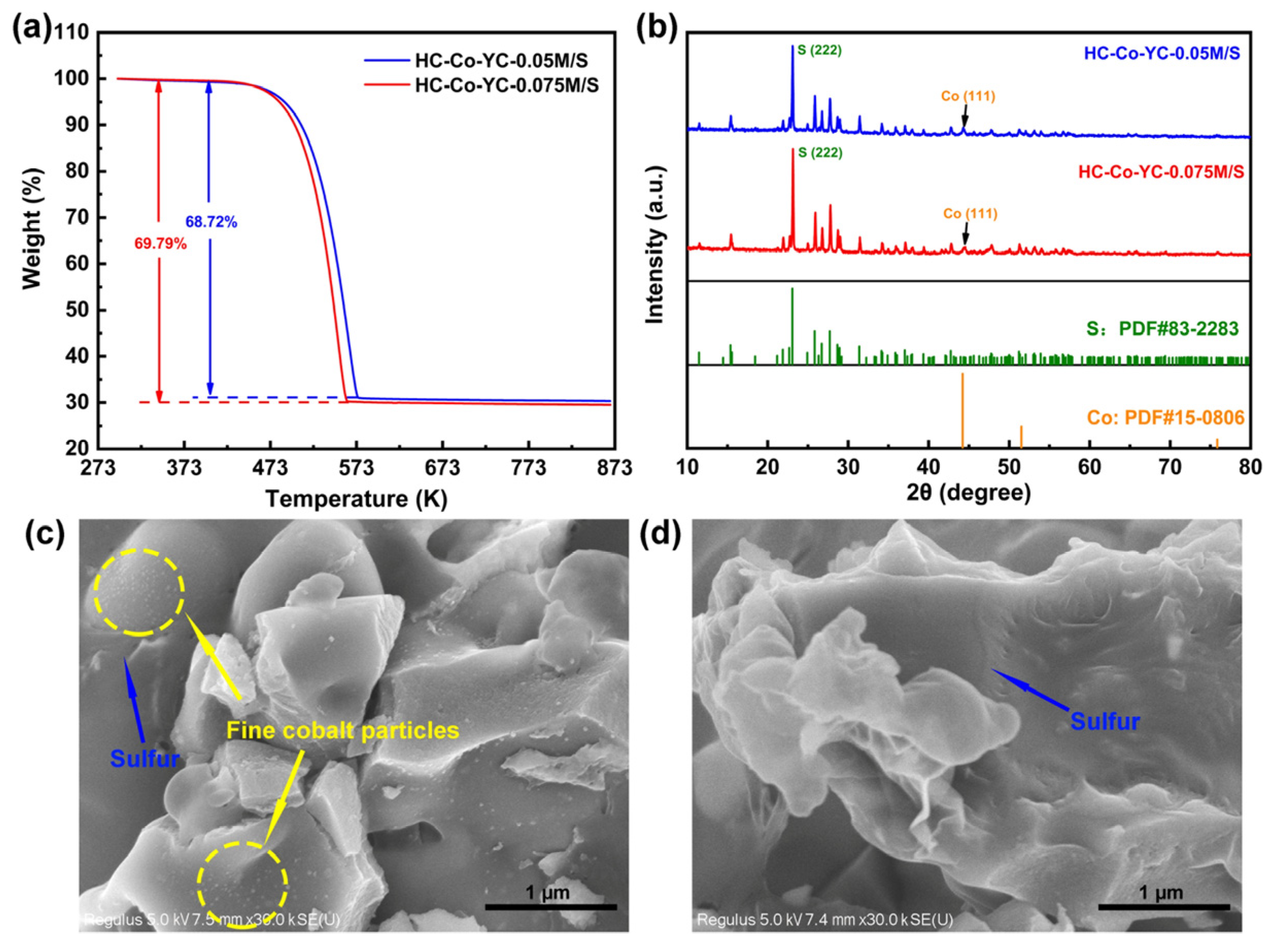
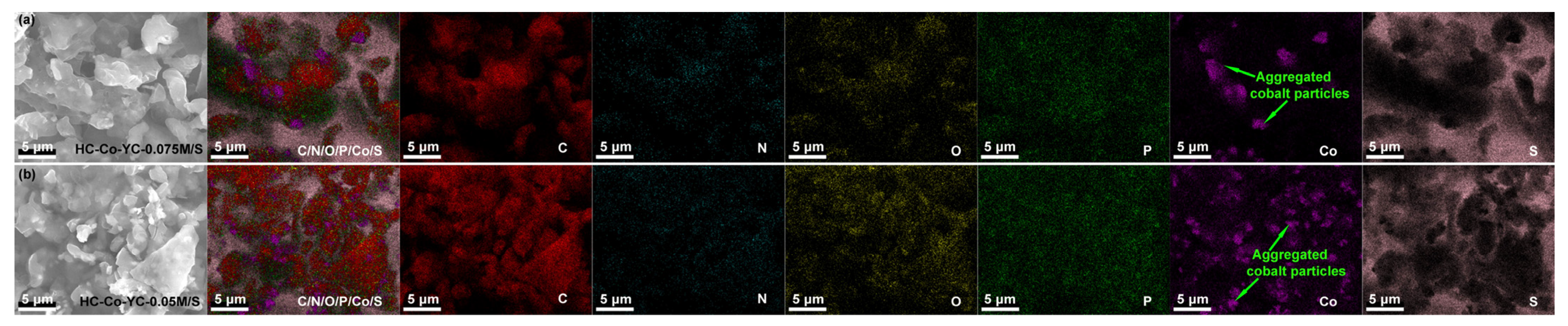
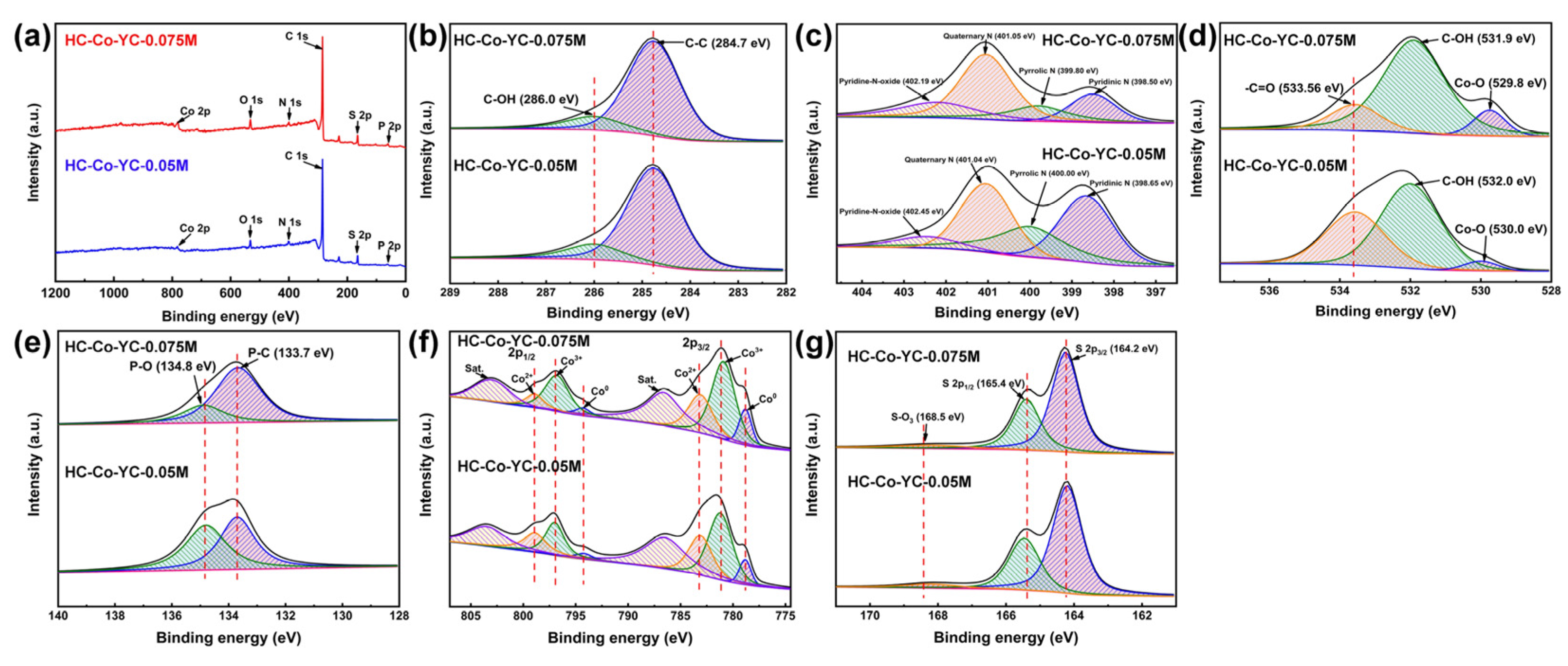
2.1. Microstructure Characterizations

The Co contents of HC–Co–YC–0.025M, HC–Co–YC–0.05M, and HC–Co–YC–0.075M were 33.986, 170.873, and 252.826 g kg−1, respectively (Figure S1). SEM images of all samples of HC–Co–YC–0.025M, HC–Co–YC–0.05M, and HC–Co–YC–0.075M are shown in Figure 1a–i. As shown in Figure 1a,b, some of the yeast-based carbon microspheres in HC–Co–YC–0.025M showed deformation. With higher cobalt content, the yeast-based carbon in HC–Co–YC–0.05M (Figure 1d,e) and HC–Co–YC–0.075M (Figure 1g,h) completely lost its natural microsphere morphology. The morphological deformation was attributed to cytoplasmic efflux. The efflux was initiated that the permeability of the yeast cell wall increased as a result of sodium dodecyl sulfonate (SDS) treatment and cleaning with ethanol and acetone, which led to an osmotic imbalance of yeast cells and an outpouring of cytoplasm. The outpouring of cytoplasm makes a hollow structure appear inside the yeast cell, and the yeast cell will deform after high-temperature pyrolysis. However, when the concentration of cobalt ions continued to increase to 0.075 M, cobalt ions would penetrate into the yeast cellular wall by virtue of concentration gradient. Note that the high concentration of CoCl2 might have exacerbated the osmotic imbalance of yeast cells. Despite being damaged substantially, three samples still had a hollow cavity structure (Figure 1c,f,h), and the structure was useful for loading and entrapping sulfur [30]. Many aggregated cobalt particles were found outside carbon materials in three samples, but numerous fine cobalt particles on the surface of yeast-based carbon materials were observed in HC–Co–YC–0.075M (Figure 1i). HR-TEM images of the HC–Co–YC–0.075M further confirmed the hollow architecture of the yeast-based carbon materials, and the carbon matrix surface was decorated with numerous fine cobalt particles (Figure 2a,b). The inset image in Figure 2a shows the lattice fringe of cobalt particles belonging to the (111) crystal plane of the cobalt phase (JCPDS 15-0806). In comparison, the HR-TEM images of HC–Co–YC–0.05M showed many aggregated cobalt particles outside the carbon materials, proving that the attempt to integrate cobalt and yeast-based carbon failed (Figure 2c,d). It was attributed to the compact structure of the yeast cell wall, which confined the agglomeration and growth of cobalt particles. However, cobalt particles that did not penetrate the yeast cells easily agglomerated and formed large particles. As for HC–Co–YC–0.075M, the fine cobalt particles on the surface of the carbon materials provided additional electrochemical active sites for redox reactions and also had a positive impact on pore formation. N2 adsorption–desorption isotherms were used to investigate the porous architectures of HC–Co–YC–0.05M and HC–Co–YC–0.075M, and the results revealed the presence of mesopores and macropores (Figure S2a–c). The BET surface areas of HC–Co–YC–0.05M and HC–Co–YC–0.075M were 3.57 and 5.19 m2 g−1, respectively. According to the IUPAC classification, there existed adsorption–desorption isotherms (type II) with a H3 hysteresis loop at high relative pressure [31]. The characterization of N2 isotherms showed that the obtained HC–Co–YC–0.05M and HC–Co–YC–0.075M were a material of macroporous structure; moreover, the hysteresis loop was due to the presence of plate-like particle aggregates which generated slit-shaped mesopores formed among the aggregates. NLDFT analysis on the pore size distribution of HC–Co–YC–0.075M revealed that the sample included mesopores of 2–20 nm and macropores of ~100 nm (Figure S2b). In comparison to the porous structure of HC–Co–YC–0.075M, HC–Co–YC–0.05M contained mesopores of 42–50 nm and macropores of 51–100 nm (Figure S2c).
Figure 3a shows the XRD patterns of HC–Co–YC–0.05M and HC–Co–YC–0.075M. The XRD patterns confirm the existence of cubic cobalt in both samples. The two samples exhibited three typical diffraction peaks of cobalt, at 44.2°, 51.5°, and 75.8°, which were attributed to the (111), (200), and (220) planes of the cobalt phase, respectively (JCPDS 15-0806). Significantly, the HC–Co–YC–0.075M showed three weak diffraction peaks at 41.6°, 47.5°, and 75.9°, which indexed the (100), (101), and (110) planes of the cobalt phase, respectively (JCPDS 05-0727), suggesting the existence of hexagonal cobalt in HC–Co–YC–0.075M. Both samples also showed a broad diffraction peak at around 26° (pink dotted box in Figure 3a), corresponding to the (002) crystal planes of the low-crystallized carbon phase (JCPDS 75-1621) [32]. Here the peak at 26° was weak because its intensity was low as compared to the high-crystalline Co. In the Raman spectra (Figure 3b), the samples of HC–Co–YC–0.05M and HC–Co–YC–0.075M presented the D-band around 1347 cm−1 (related to the presence of amorphous carbon) and the G-band around 1595 cm−1 (associated with in-plane stretching vibrations of sp2 carbon bonds), which were characteristic to carbon-based material [33]. Concurrently, the occurrence of stacking disorder made the G′-band peaks ranged from 2500 cm−1 to 2800 cm−1 be broader [34,35]. The Raman results proved that the two samples had a feature of carbons with some ordering of the graphene basal planes.
The composites of HC–Co–YC–0.05M/S and HC–Co–YC–0.075M/S were obtained by melting sulfur into HC–Co–YC–0.05M and HC–Co–YC–0.075M; the TGA curves in Figure 4a show that the sulfur contents in HC–Co–YC–0.05M/S and HC–Co–YC–0.075M/S were 68.72 wt% and 69.79 wt%, respectively. According to the TGA results, the temperature for complete evaporation of sulfur in HC–Co–YC–0.05M/S was higher than that for HC–Co–YC–0.075M/S, attributed to the weak interactions between the nonpolar sulfur and polar surface of carbon materials decorated with fine cobalt particles in HC–Co–YC–0.075M/S. The XRD patterns in Figure 4b further support successful loading of sulfur into the two composites; a succession of distinctive orthorhombic sulfur peaks is clearly visible in HC–Co–YC–0.05M/S and HC–Co–YC–0.075M/S. The homogeneous distributions of sulfur in the two composites of HC–Co–YC–0.05M/S and HC–Co–YC–0.075M/S are presented in Figure 4c,d. Numerous fine cobalt particles were observed on the surface of the yeast-based carbon materials in the HC–Co–YC–0.075M/S composite (Figure 4c). Furthermore, EDS elemental mapping images of HC–Co–YC–0.075M/S revealed that carbon, nitrogen, oxygen, phosphorus, cobalt, and sulfur were well-distributed on the surface of the carbon materials, with a small quantity of aggregated cobalt particles present outside of the carbon materials (Figure 5a—Co). The homogeneously distributed N, O, P, and Co on the surface of the carbon materials could be in close contact with sulfur, thereby minimizing the shuttle effect of LiPSs and enhancing the cycle stability of the Li–S battery. The chemical adsorption of LiPSs by these naturally doped nitrogen, oxygen, and phosphorus elements in yeast-based carbon is more efficient than the physical adsorption of carbon powder with a high specific surface area (such as super P and Ketjen black) for LiPSs. In contrast to HC–Co–YC–0.075M/S (Figure 5b—Co), many aggregated cobalt particles were discovered outside of the carbon materials in HC–Co–YC–0.05M/S, which was compatible with the SEM (Figure 1d,f) and TEM data (Figure 2c,d). The chemisorption ability of cobalt to polysulfides was reduced by the lower surface-to-volume ratio of aggregated cobalt particles [36].
The surface chemical valence states of HC–Co–YC–0.075M/S were examined through XPS analysis. The XPS survey shown in Figure 6a revealed the co-existence of elements C, N, O, P, Co, and S in the composite of HC–Co–YC–0.075M/S. The C 1s spectrum indicated the presence of carbon in the composite based on two absorption peaks at 284.7 and 286.0 eV, corresponding to C–C and C–OH bonds, respectively (Figure 6b) [32]. Four characteristic peaks belonging to pyridinic N, pyrrolic N, quaternary N, and pyridine-N-oxide were identified in the N 1s spectrum (Figure 6c) [37,38]. The chemisorption of carbon materials to polysulfides could be improved by these N-doping functional groups. The O 1s spectrum in Figure 6d contained two standard peaks at 531.9 and 533.56 eV, assigned to C–OH and –C=O bonds, respectively, as well as a third peak at 529.8 eV attributable to the Co–O bond [26]. In the P 2p spectrum, two peaks of P–C (133.7 eV) and P–O (134.8 eV) can be seen (Figure 6e). Elements P and N, derived from the degradation of protein and nucleic acid in yeast cells, can enhance the electronic conductivity of HC–Co–YC–0.075M/S while lowering the energy barrier of ion penetration, resulting in improved performance of the Li–S battery [24,39,40]. The high-resolution Co 2p spectrum in Figure 6f showed that there were three valence states of cobalt, in HC–Co–YC–0.075M/S, Co0, Co3+, and Co2+ [26]. The Co 2p3/2 signal was deconvoluted into four peaks at 778.81 eV (Co0), 780.9 eV (Co3+), 783.1 eV (Co2+), and 786.6 eV (satellite), whereas the Co 2p1/2 signal was fitted to four peaks at 794.3 eV (Co0), 796.8 eV (Co3+), 798.9 eV (Co2+), and 803.0 eV (satellite). These results confirmed the presence of metallic Co in HC–Co–YC–0.075M/S, in accordance with the TEM and XRD results, as well as their partial oxidation on the surface of carbon materials such as cobalt oxide. Abundant surface-active sites formed by fine cobalt particles and cobalt oxide enhanced the chemical confinement of LiPSs and accelerated the redox reaction of the battery [41]. In addition, the S 2p spectrum in Figure 6g showed two significant peaks, at 164.2 and 165.4 eV, belonging to S 2p3/2 and S 2p1/2 of S8 molecules, respectively, and a minor signal at 168.5 eV related to S–O3 generated by the sulfur–oxygen reaction; this indicated stable storage of sulfur in the carbon matrix [18,34].

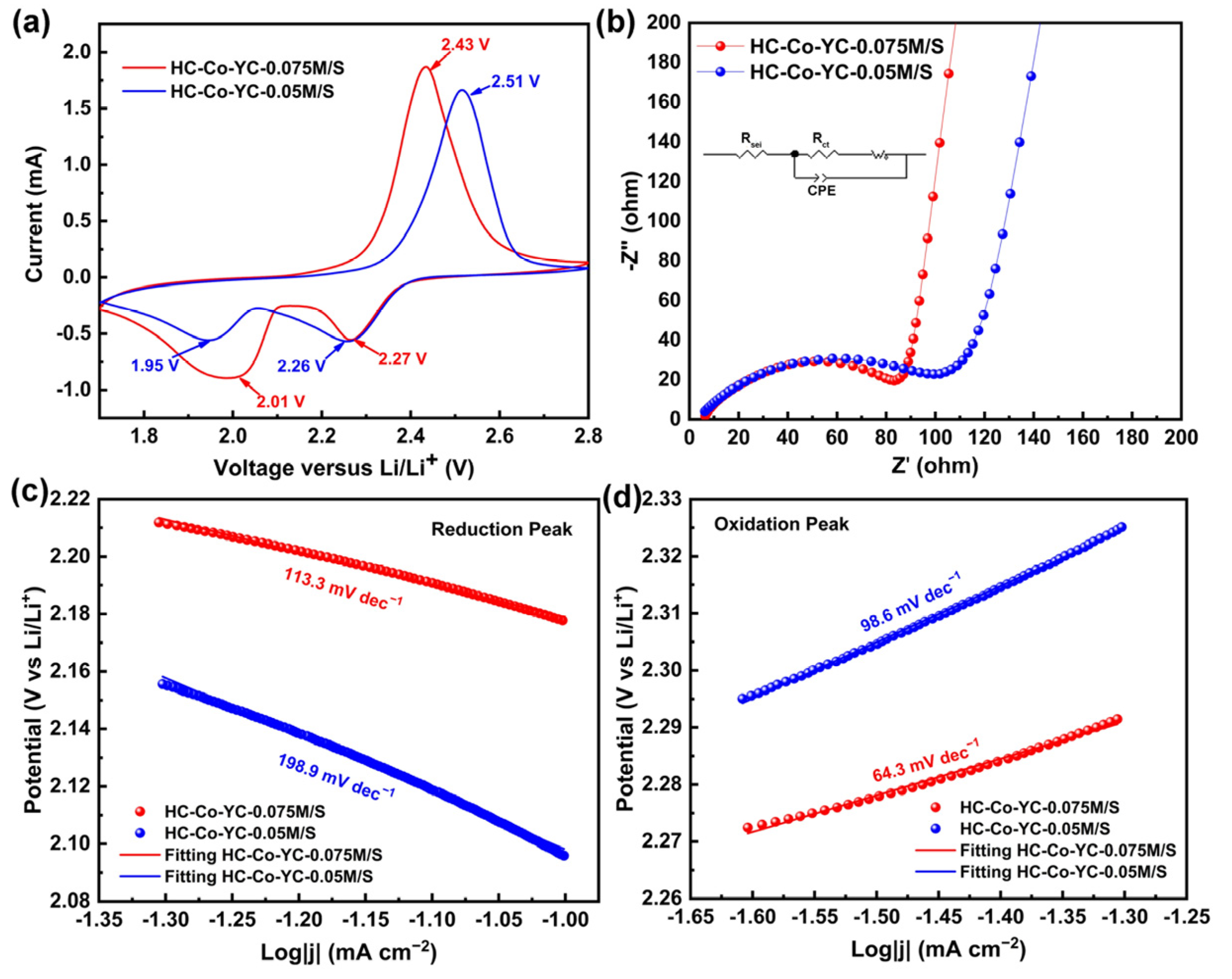
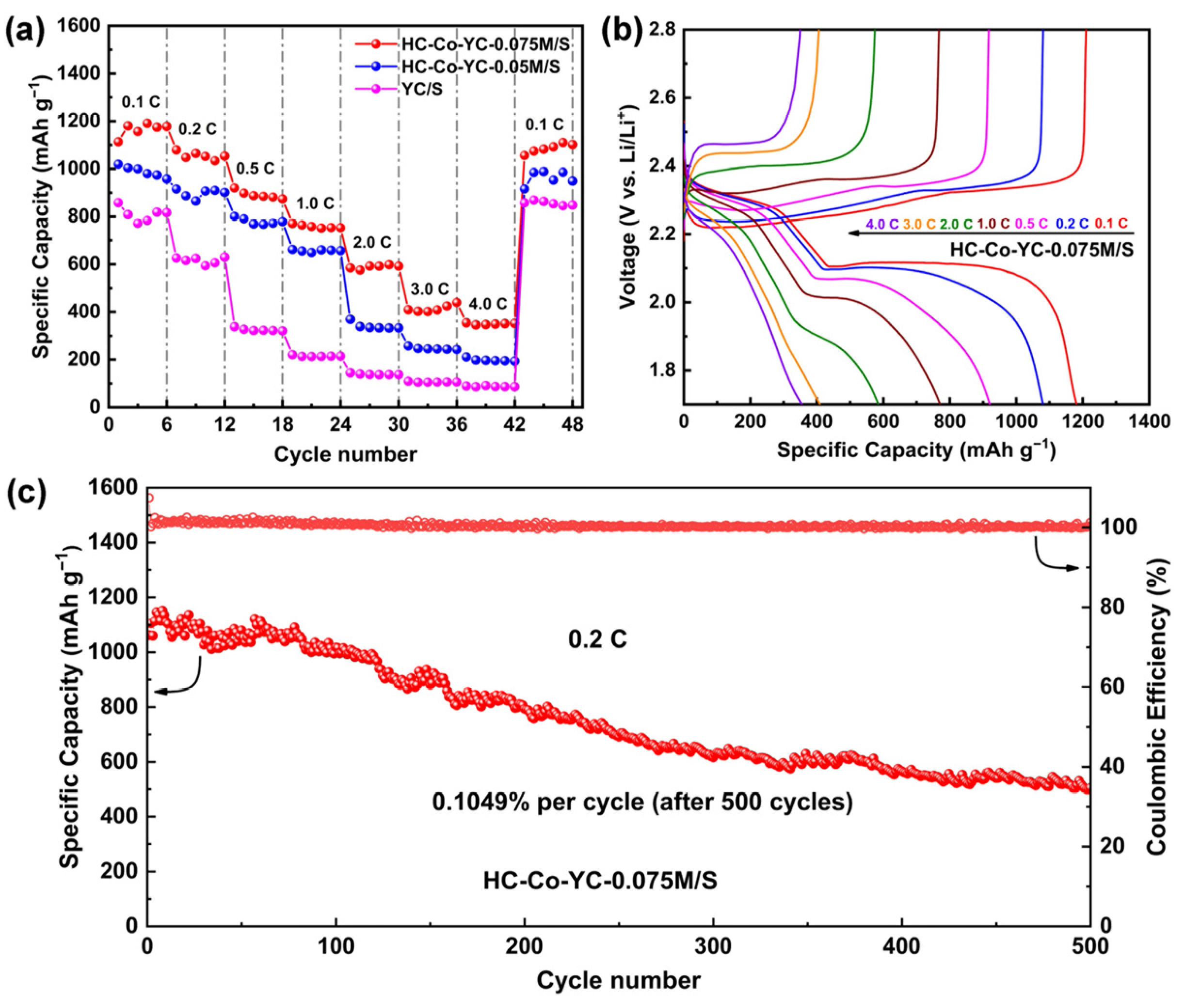
2.2. Electrochemical Performance

The electrodes of HC–Co–YC–0.05M/S and HC–Co–YC–0.075M/S serving as the cathode of the Li–S batteries were characterized by CV, EIS, and Tafel tests on an electrochemical workstation. The CV curves were employed to evaluate the redox reactivity of the two fresh electrodes at a scanning rate of 0.1 mV s−1 within a voltage window of 1.7–2.8 V, as shown in Figure 7a. Both electrodes had two separate cathodic peaks representing the discharge reaction of the battery, and a single anodic peak representing the charge reaction of the battery [42,43]. During the cathodic scan, the first reduction peak at 2.27 V (HC–Co–YC–0.075M/S cathode) or 2.26 V (HC–Co–YC–0.05M/S cathode) arose from the conversion of solid-state cyclic S8 into liquid-state long-chain polysulfides (Li2Sn, 4 ≤ n ≤ 8), while the second reduction peak at 2.01 V (HC–Co–YC–0.075M/S electrode) or 1.95 V (HC–Co–YC–0.05M/S electrode) arose from the subsequent formation of end-product Li2S. In the anodic scan, the oxidation peak at 2.43 V (HC–Co–YC–0.075M/S electrode) or 2.51 V (HC–Co–YC–0.05M/S electrode) was attributed to the oxidation of sulfur species. When the CV curves of the two electrodes were compared, the HC–Co–YC–0.075M/S electrode displayed a higher peak current and smaller peak potential gap than the HC–Co–YC–0.05M/S electrode, demonstrating that the electrochemical properties of the Li–S batteries were significantly enhanced by the successful implantation of fine cobalt particles into HC–Co–YC–0.075M. The charge transfer capabilities of the HC–Co–YC–0.05M/S and HC–Co–YC–0.075M/S electrodes were explored by EIS. There was a semicircle in the high-frequency region of the Nyquist plots (Figure 7b), which represented the overlap between solid electrolyte interphase resistance (Rsei) and charge transfer resistance (Rct) [25,44]. After equivalent circuit fitting, the Rct of the HC–Co–YC–0.075M/S electrode (88.2 Ω) was lower than that of the HC–Co–YC–0.05M/S electrode (116 Ω), further demonstrating that the integrated structure of metal Co and yeast-based carbon endowed the former with faster electrochemical reaction kinetics. Figure S3 showed the EIS plots of HC–Co–-YC–0.05M/S and HC–Co–YC–0.075M/S electrodes after 10th cycle, and the Rct tended to be stable after 10 cycles due to sulfur redistribution with cycling [45]. The HC–Co–YC–0.075M/S electrode also showed a smaller Rct (23.48 Ω) than the HC–Co–YC–0.05M/S electrode (46.69 Ω). The resistance values of the HC–Co–YC–0.075M/S electrode and other reported microbe-based carbon/sulfur composite electrodes are shown in Table 1. Metal particles implanted in yeast-based carbon materials effectively reduced the resistance of the electrode compared to that of other electrodes, without incorporation of metal particles. The kinetics of the redox reactions of the two electrodes were investigated by analyzing the Tafel plots (Figure 7c,d) [46,47,48]. The HC–Co–YC–0.075M/S electrode exhibited smaller Tafel slopes than the HC–Co–YC–0.05M/S electrode at the reduction peak oxidation peaks, which suggested rapid reduction conversion of LiPSs to Li2S2/Li2S and fast oxidation reaction of Li2S to sulfur in the HC–Co–YC–0.075M/S electrode.
Li-ion diffusion of the HC–Co–YC–0.05M/S and HC–Co–YC–0.075M/S electrodes was explored by analyzing CV curves under sweep rates of 0.05–0.4 mV s−1 within the voltage window of 1.7–2.8 V (Figure 8a,b). The current peaks of the cathode and anode have a linear connection with the square root of the scanning rate, indicating that the reaction is diffusion-limited [46]. The Li-ion diffusion kinetics of the two electrodes were compared based on the slopes of the fitted lines (Figure 8c–e), with greater slope of the fitted line indicating a larger Li-ion diffusion coefficient. The Li-ion diffusion coefficients were calculated using the Randles–Sevcik equation (Equation (S1)), and the results are summarized in Figure 8f [45,51,52,53]. Peaks C1, C2, and A1 of the HC–Co–YC–0.075M/S electrode had DLi+ values of 0.573, 1.169, and 4.553 × 10⁻⁸ cm2 s−1, whereas peaks C1, C2, and A1 of the HC–Co–YC–0.05M/S electrode had DLi+ values of 0.568, 0.541, and 3.185 × 10⁻⁸ cm2 s−1, respectively. The enhanced Li-ion diffusivity on the HC–Co–YC–0.075M/S electrode surface can be attributed to the well-ordered growth of solid sulfur species on the surface of the electrode (induced by fine cobalt particles effectively preventing the formation of a thick insulating layer on the surface of the cathode [51]) and the rich mesoporous structure of HC–Co–YC–0.075M that facilitates fast Li-ion transport. The peak voltages of the cathode/anode of the HC–Co–YC–0.075M/S and HC–Co–YC–0.05M/S electrodes showed a clear shift to a more negative/positive position, resulting in greater polarization of the electrode with an increase in scan rate, as illustrated in Figure 8a,b. As shown in Figure 8f, for the HC–Co–YC–0.075M/S electrode there was a smaller potential gap between peak voltages (∆V) than for the HC–Co–YC–0.05M/S electrode, suggesting higher stability and capacity of the HC–Co–YC–0.075M/S electrode.
The rate capabilities of the YC/S, HC–Co–YC–0.05M/S, and HC–Co–YC–0.075M/S electrodes were examined at current densities of 0.1–4.0 C. As shown in Figure 9a, the discharge specific capacities of the HC–Co–YC–0.075M/S electrode were 1113.2, 1079.7, 920.6, 770.4, 585.0, 409.3, and 354.8 mAh g−1 at 0.1, 0.2, 0.5, 1.0, 2.0, 3.0, and 4.0 C, respectively, with continued cycling at each rate for six cycles; these values were all higher than those of the HC–Co–YC–0.05M/S electrode (1019.5, 916.1, 801, 661.6, 368.8, 257.8, and 210.8 mAh g−1 at 0.1, 0.2, 0.5, 1.0, 2.0, 3.0, and 4.0 C, respectively) and the YC/S electrode (858.1, 626, 338.7, 220.3, 144.9, 109.4, 89.5 mAh g−1 at 0.1, 0.2, 0.5, 1.0, 2.0, 3.0, and 4.0 C, respectively). When the current density returned to 0.1 C in the 43rd cycle, the discharge specific capacity of the HC–Co–YC–0.075M/S electrode had recovered to 1056.7 mAh g−1. This suggested excellent reversibility and rate cyclability of the HC–Co–YC–0.075M/S electrode, which was attributed to the implantation of cobalt nanoparticles into the carbon matrix and better conductivity of the electrode. The charge–discharge curves of the YC/S, HC–Co–YC–0.05M/S, and HC–Co–YC–0.075M/S electrodes at different current densities are presented in Figure 9b and Figure S4a,b. There were two distinct discharge plateaus in the discharge process of both the HC–Co–YC–0.05M/S and HC–Co–YC–0.075M/S electrodes, but not in that of the YC/S electrode. One of these was the higher discharge plateau corresponding to the reduction reaction of S8 to S2–4, with an average voltage of 2.3 V, and the other was the lower discharge plateau corresponding to the subsequent reaction of Li2S4 to Li2S2/Li2S, with an average voltage of 2.1 V. Because the capacity generated by the lower discharge plateau was 2–3 times larger than capacity generated by the higher discharge plateau, the lower discharge plateau played a significant role in the discharge process [54]. The lower plateau of the HC–Co–YC–0.075M/S electrode did not disappear until the current density reached 3.0 C, but the lower plateau of the HC–Co–YC–0.05M/S electrode vanished at 2.0 C. This indicated that the fine cobalt particles implanted on the surface of the carbon materials might effectively improve the sluggish reaction kinetics of the lower plateau. The long-cycling stability of the HC–Co–YC–0.05M/S and HC–Co–YC–0.075M/S electrodes was characterized by galvanostatic charge–discharge curves within the voltage window of 1.7–2.8 V at a current density of 0.2 C, as shown in Figure 9c and Figure S4c–e. The initial discharge specific capacity of the HC–Co–YC–0.075M/S electrode was 1061.9 mAh g−1. Then, after the third cycle, the discharge specific capacity exceeded 1100 mAh g−1, which was attributable to the activation of the electrode. The HC–Co–YC–0.075M/S electrode remained at a high discharge specific capacity of 504.9 mAh g−1 after 500 cycles, with a capacity retention of 47.5% and capacity fading rate of 0.1049% per cycle, which was superior to the result of the HC–Co–YC–0.05M/S electrode. The charge–discharge curve of the HC–Co–YC–0.05M/S electrode was exceedingly unstable after 200 cycles, and the discharge capacity dropped dramatically. This result confirmed that the successful implantation of fine cobalt particles into the yeast-based carbon materials was essential for maintaining the long-term cycle stability of the Li–S batteries. The discharge capacity of the Li–S batteries can be classified as high plateau discharge capacity (QH) or low plateau discharge capacity (QL) [43]. The theoretical capacity ratio of QL to QH is approximately 3, but the actual ratio is ≤2.5 [1,54]. Figure S4f–g shows that the QL/QH ratio of the HC–Co–YC–0.075M/S electrode was maintained at 2.0–2.5, which was higher than that of the HC–Co–YC–0.05M/S electrode (1.7–1.9). This indicated that the fine cobalt particles implanted in the yeast-based carbon materials effectively catalyzed rapid conversion of LiPSs to Li2S, consistent with the Tafel plots.
The CV test of the symmetrical cells and the potentiostatic Li2S precipitation experiments were conducted to investigate the catalytic effect of HC–Co–YC–0.075M in Li–S batteries [55,56]. As shown in Figure S5a, with the addition of Li2S6–containing electrolyte, HC–Co–YC–0.075M-CP symmetrical cells displayed a higher current response than YC–CP, while HC–Co–YC–0.075M–CP symmetrical cells without Li2S6 had almost no current response. As seen from Figure S5b,c, the precipitation specific capacity of Li2S on the HC–Co–YC–0.075M–CP surface (51 mAh g−1) was higher than that on the YC–CP surface (24.2 mAh g−1), suggesting that fine cobalt particles in yeast–based enhanced the precipitation of Li2S. The results proved that fine cobalt particles in yeast–based carbon could significantly accelerate the reaction of polysulfides conversion. To explore the LiPSs adsorption ability of HC–Co–YC materials, 5 mg of YC, HC–Co–YC–0.05M and HC–Co–YC–0.075M were stirred with Li2S6–containing electrolytes (5 mL) and rested for 24 h (Figure S6). Obviously, after mixing with HC–Co–YC–0.075M, the mixed solution became completely clean and colorless, while the yellowish polysulfide could be still observed in other mixed solution. It proved that abundant fine cobalt particles on the surface of yeast-based carbon had strong adsorption capacity for LiPSs. Comparison of the capacity and cycling performance of the HC–Co–YC–0.075M/S electrode with those of previously reported electrodes assembled with hollow microbe-based carbon with a low specific surface area is shown in Table S1. In the case of carbon hosts with low specific surface area, the integrated structure of metal Co and yeast-based carbon provided a large number of active sites to chemically confine lithium polysulfides and rapidly catalyze the conversion of sulfur species, resulting in a high reversible capacity and remarkable cycle stability. Conversely, other reported electrodes without implanted metal particles performed poorly during cycling. The results further confirmed that the implantation of metal particles into the carbon matrix was critical for preventing the shuttle effect and stabilizing the electrode structure.

3. Experiment Section

3.1. Preparation of HC–Co–YC

Freeze-dried yeasts were prepared according to a previously reported method [26]. First, the yeast cells were activated by mixing 2% glucose solution with Angel yeast and incubating overnight at room temperature. Then, the wet yeast cells were collected by centrifugation at 5000 rpm for 3 min. Finally, freeze-dried powders were obtained by freeze-drying the wet yeast cells.
Freeze-dried yeast (4 g) was suspended in 50 mL of deionized water containing 1% SDS for 30 min under agitation and then incubated statically at 333 K for 2 h. The wet yeast treated with SDS was collected after centrifugation (5000 rpm for 3 min) and then rinsed with deionized water, ethanol, acetone, ethanol again, and deionized water again. The washed yeast was mixed homogeneously with three different concentrations of CoCl2 solution (0.025, 0.05, and 0.075 M) to form three mixtures, which were allowed to stand at 353 K. The three mixtures were then dried to powder using a vacuum freeze drier. Finally, the three freeze-dried powders were carbonized in a tube furnace at 973 K under an argon atmosphere to produce three HC–Co–YC samples. The HC–Co–YC samples treated with 0.025, 0.05, and 0.075 M CoCl2 solution were denoted as HC–Co–YC–0.025M, HC–Co–YC–0.05M, and HC–Co–YC–0.075M, respectively. Yeast carbon (YC) was prepared by pyrolysis of yeast cells at 973 K.

3.2. Preparation of Three HC–Co–YC/S Composites

To obtain HC–Co–YC/S composites, sulfur was infiltrated into the HC–Co–YC samples using a previously reported melt-diffusion process [24]. HC–Co–YC–0.05M or HC–Co–YC–0.075M was mixed with commercial sulfur at a weight ratio of 7:3. Subsequently, the mixtures were sealed in a glass container with Ar atmosphere, heated at 428 K for 6 h, and then heated further at 473 K for 30 min. HC–Co–YC–0.05M/S and HC–Co–YC–0.075M/S composites were successfully prepared via this method. The preparation method of YC/S was the same as that of HC–Co–YC/S.

3.3. Material Characterization

X-ray diffraction (XRD; D-8 Advance; Bruker; Karlsruhe; Germany) was used to investigate the crystallinity and phase structures of all powder samples, with Cu Kα (λ = 1.5406 Å) radiation. The cobalt contents of HC–Co–YC–0.025M, HC–Co–YC–0.05M, and HC–Co–YC–0.075M were measured by inductively coupled plasma–optical emission spectrometry (ICP-OES; Spectro Arcos; Ametek; Kleve; Germany). The morphological characteristics of the three samples (HC–Co–YC–0.025M, HC–Co–YC–0.05M, and HC–Co–YC–0.075M) and two composites (HC–Co–YC–0.05M/S and HC–Co–YC–0.075M/S) were observed by scanning electron microscopy (SEM) at 5.0 kV (Regulus 8230; Hitachi Ltd.; Tokyo; Japan). The hollow cavity of the yeast-based carbon and crystalline phase of the metal particles in the HC–Co–YC–0.05M and HC–Co–YC–0.075M samples were characterized by high-resolution transmission electron microscopy (HR-TEM; JEM-F200; JEOL Ltd.; Tokyo, Japan). The Raman spectra of the HC–Co–YC–0.05M and HC–Co–YC–0.075M samples were analyzed using a confocal Raman instrument (LabRAM HR Evolution; HORIBA Ltd.; Kyoto, Japan) under 532 nm laser excitation. N2 adsorption–desorption isotherms were measured using a surface area and porosity analyzer (ASAP 2460; Micromeritics Co. Ltd., Norcross, GA, USA) at 77 K. The Brunauer–Emmett–Teller (BET) method was utilized to calculate the specific surface areas using adsorption data in a relative pressure range from 0.01 to 0.99, and the pore size distribution was analyzed according to non-local density functional theory (NLDFT). The sulfur contents of the HC–Co–YC–0.05M/S and HC–Co–YC–0.075M/S composites were determined using thermogravimetric analysis (TGA; SDT Q600; TA Instruments Inc., New Castle, DE, USA) from 298 to 873 K with a heating rate of 10 K min−1 in a nitrogen atmosphere. The chemical valences of various elements on the surface of the HC–Co–YC–0.075M/S composite were analyzed by X-ray photoelectron spectroscopy (XPS; ESCALAB 250Xi; Thermo Fisher Scientific Inc., Waltham, MA, USA).

3.4. Electrochemical Characterization

The electrode slurry of the Li–S batteries was fabricated by mixing HC–Co–YC–0.05M/S or HC–Co–YC–0.075M/S with carbon nanotubes and polyvinylidene fluoride at a mass ratio of 8:1:1 in N-methyl-2-pyrrolidone. Then, the electrode slurry was coated uniformly on aluminum foil with a coater and dried at 328 K for 14 h in a vacuum drying oven to obtain cathodes. CR2025 coin cells were assembled in an argon-filled glove box (<1 ppm H2O and <1 ppm O2) and used as test cells to explore the electrochemical properties of the composite/sulfur electrode. The final areal sulfur mass loading on each electrode was held within the range of 1–1.5 mg cm−2. The coin cells were obtained using a cathode (HC–Co–YC–0.05M/S or HC–Co–YC–0.075M/S), lithium foil anode, and Celgard 2400 separator. The electrolyte was 1 M bis-(trifluoromethane)sulfonamide lithium salt (LiTFSI) in a mixture of 1,3-dioxolane/1,2-dimethoxyethane (DOL/DME; volume ratio of 1:1) with 2 wt% LiNO3 as an electrolyte additive. The amount of electrolyte in the coin cell was 20 μL mg−1. The 5 mM Li2S6 solution was prepared by dissolving of sulfur and Li2S at the molar ratio of 5:1 in the above-mentioned electrolyte. After that, the mixed solution was stirred for 24 h at 333 K. The 5 mM Li2S6 electrolytes was used to the visual adsorption test of lithium polysulfides. The rate capabilities and long-term cycle stabilities of the coin cells were tested using a LAND-CT2001A battery tester (Land Electronic Co. Ltd.; Wuhan; China) within the voltage range of 1.7–2.8 V at room temperature. Electrochemical impedance spectroscopy (EIS) and cyclic voltammetry (CV) measurements were carried out with a CS350 electrochemical workstation (Wuhan Corrtest Instruments Inc.; Wuhan; China). EIS analysis was performed in the frequency range of 100 kHz to 0.01 Hz, and CV curves were obtained at scanning rates of 0.05, 0.1, 0.2, 0.3, and 0.4 mV s−1.

3.5. Experiment of the Li2S Nucleation

The experimental operation referred to the method proposed by Chiang et al. [55]. The Li2S8 solution was prepared by mixing Li2S and sulfur at a molar ratio of 1:7 in electrolyte (tetraglyme with additional 1 M LiTFSI) at 333 K with stirring for 24 h. The ethanol solution of HC–Co–YC–0.075M and YC (2 mg cm−2) were dropped onto the carbon fiber papers (CP). After drying, HC–Co–YC–0.075M–CP and YC–CP served as cathode and lithium foil acted as anode. An amount of 20 μL 0.2 M Li2S8 electrolyte was dropped on the cathode and 20 μL blank electrolyte was dropped on the anode. The prepared coin cells were galvanostatically discharged to 2.06 V at a current density of 0.112 mA, and then held the voltage at 2.05 V until the current decreased to 10−5 A.

3.6. Catalytic Studies of Polysulfide Conversion

Li2S6 symmetric cells were used to investigate the electrocatalytic effect of HC–Co–YC [56]. Symmetric cells were prepared by the previously reported method [52]. The catholyte was prepared by adding Li2S and sulfur (at a molar ratio of 1:5) into the above-mentioned electrolyte. HC–Co–YC–0.075M and YC (0.5 mg cm−2) were loaded onto the CP, and 40 μL 0.5 M Li2S6 electrolyte was added into each coin cell. CV measurements was performed at a scan rate of 50 mV S−1 in the voltage from −0.8 to 0.8 V.

4. Conclusions

In conclusion, an integrated architecture of metal Co and yeast-based carbon was designed and fabricated by the impregnation–pyrolysis method using a 0.75 M cobalt chloride solution. The hollow cavity architecture of the yeast-based carbon materials in HC–Co–YC–0.075M, which were homogeneously adorned with many fine cobalt particles, was revealed through morphology and structure analyses. The cathode built with HC–Co–YC–0.075M/S displayed excellent rate and cycling performance, because these cobalt particles served as multiple active sites that successfully prevented the shuttle effect and catalyzed a rapid redox reaction. At a current density of 0.2 C, the initial discharge capacity of the HC–Co–YC–0.075M/S electrode was 1061.9 mAh g−1; after 500 cycles, the capacity retention was high, at 504.9 mAh g−1, with a decay rate of 0.1049% per cycle. All of the results showed the excellent electrochemical performance of the electrode made by implanting the carbon host with metal particles, even though the specific surface area of the carbon host was quite low (which facilitates the application of microbe-based carbon materials to lithium–sulfur batteries).

Supplementary Materials

The following supporting information can be downloaded at: https://www.mdpi.com/article/10.3390/catal12090951/s1, Figure S1: the contents of cobalt in HC–Co–YC–0.025M, HC–Co–YC–0.05M and HC–Co–YC–0.075M samples; Figure S2: (a) N2 adsorption–desorption isotherms of HC–Co–YC–0.05M and HC–Co–YC–0.075M, pore size distributions of (b) HC–Co–YC–0.075M and (c) HC–Co–YC–0.05M; Equation S1: the Randles–Sevcik equation; Figure S3: EIS plots of the HC–Co–YC–0.05M/S and HC–Co–YC–0.075M/S electrodes after 10 cycles (inset is the equivalent circuit); Figure S4: charge–discharge voltage curves of the (a) HC–Co–YC–0.05M/S, and (b) YC/S electrodes at various current densities; (c) long-term cycle stabilities of the HC–Co–YC–0.05M/S electrode at 0.2 C; charge–discharge curves of the (d) HC–Co–YC–0.075M/S and (e) HC–Co–YC–0.05M/S electrodes at 0.2 C; and capacity contributions of QH, QL and the QL/QH ratio values of the representative cycles for the (f) HC–Co–YC–0.075M/S and (g) HC–Co–YC–0.05M/S electrodes; Figure S5: (a) CV curves of symmetrical cells of YC–CP and HC–Co–YC–0.075M–CP electrodes with and without Li2S6 at a scan rate of 50 mV S−1, potentiostatic discharging curves of Li2S8/tetraglyme solution at 2.05 V on (b) YC–CP, and (c) HC–Co–YC–0.075M–CP; Figure S6: adsorption test of Li2S6 on different yeast-based carbon materials; Table S1: comparison of long-cycling stability of previously reported electrodes assembled with hollow microbe-based carbon host with this work. Table S1. Comparison of long-cycling stability of previously reported electrodes assembled with hollow microbe-based carbon host with this work. Equation S1: the Randles-Sevcik equation. References [25,26,30,49,50] are cited in the supplementary materials.

Author Contributions

Conceptualization, Y.Z. and J.-L.M.; methodology, Y.Z. and J.-L.M.; formal analysis, Y.Z. and J.-L.M.; investigation, Y.Z. and J.-L.M.; resources, J.-L.M. and W.-J.F.; data curation, Y.Z.; writing—original draft preparation, Y.Z.; writing—review and editing, J.-L.M. and W.-J.F.; visualization, Y.Z. and J.-L.M.; supervision, W.-J.F.; project administration, W.-J.F.; funding acquisition, J.-L.M. and W.-J.F. All authors have read and agreed to the published version of the manuscript.

Funding

The paper was funded by the National Natural Science Foundation of China (Grant No. 21965019), Cuiying Scientific and Technological Innovation Program of Lanzhou University Second Hospital (Grant No. 2020QN-02), Natural Science Foundation of Gansu Province, China (Grant No. 21JR11RA108).

Acknowledgments

The authors would like to acknowledge the financial support from the National Natural Science Foundation of China, Cuiying Scientific and Technological Innovation Program of Lanzhou University Second Hospital, Natural Science Foundation of Gansu Province, China and Hong-Liu First-class Disciplines Development Program of Lanzhou University of Technology.

Conflicts of Interest

The authors declare no conflict of interest.

References

  1. Fang, R.; Zhao, S.; Sun, Z.; Wang, D.W.; Cheng, H.M.; Li, F. More reliable lithium-sulfur batteries: Status, solutions and prospects. Adv. Mater. 2017, 29, 1606823. [Google Scholar] [CrossRef] [PubMed]
  2. Service, R.F. A boost for lithium-sulfur batteries. Science 2013, 339, 20–21. [Google Scholar] [CrossRef] [PubMed]
  3. Bruce, P.G.; Freunberger, S.A.; Hardwick, L.J.; Tarascon, J.M. Li-O2 and Li-S batteries with high energy storage. Nat. Mater. 2011, 11, 19–29. [Google Scholar] [CrossRef]
  4. Yu, X.; Manthiram, A. A progress report on metal-sulfur batteries. Adv. Funct. Mater. 2020, 30, 2004084. [Google Scholar] [CrossRef]
  5. Jana, M.; Xu, R.; Cheng, X.B.; Yeon, J.S.; Park, J.M.; Huang, J.Q.; Zhang, Q.; Park, H.S. Rational design of two-dimensional nanomaterials for lithium-sulfur batteries. Energy Environ. Sci. 2020, 13, 1049–1075. [Google Scholar] [CrossRef]
  6. Yu, X.; Manthiram, A. Electrode-electrolyte interfaces in lithium-sulfur batteries with liquid or inorganic solid electrolytes. Acc. Chem. Res. 2017, 50, 2653–2660. [Google Scholar] [CrossRef] [PubMed]
  7. Lang, S.Y.; Xiao, R.J.; Gu, L.; Guo, Y.G.; Wen, R.; Wan, L.J. Interfacial mechanism in lithium-sulfur batteries: How salts mediate the structure evolution and dynamics. J. Am. Chem. Soc. 2018, 140, 8147–8155. [Google Scholar] [CrossRef] [PubMed]
  8. Jin, Y.; Zhou, G.; Shi, F.; Zhou, D.; Zhao, J.; Liu, K.; Liu, Y.; Zu, C.; Chen, W.; Zhang, R.; et al. Reactivation of dead sulfide species in lithium polysulfide flow battery for grid scale energy storage. Nat. Commun. 2017, 8, 462. [Google Scholar] [CrossRef]
  9. Deng, R.; Wang, M.; Yu, H.; Luo, S.; Li, J.; Chu, F.; Liu, B.; Wu, F. Recent advances and applications toward emerging lithium-sulfur batteries: Working principles and opportunities. Energy Environ. Mater. 2022, 5, 777–799. [Google Scholar] [CrossRef]
  10. Zhang, Q.; Huang, Q.; Hao, S.M.; Deng, S.; He, Q.; Lin, Z.; Yang, Y. Polymers in lithium-sulfur batteries. Adv. Sci. 2022, 9, 2103798. [Google Scholar] [CrossRef]
  11. Chen, J.; Feng, W.; Zhao, W.; Shi, Z. Transition metal phosphide composite with metal-organic framework and carbon nanotubes for high-performance lithium-sulfur batteries. J. Alloys Compd. 2022, 890, 161794. [Google Scholar] [CrossRef]
  12. Feng, W.; Chen, J.; Niu, Y.; Zhao, W.; Zhang, L. CeO2 composite metal organic framework is used to construct high-performance lithium-sulfur batteries. J. Alloys Compd. 2022, 906, 164341. [Google Scholar] [CrossRef]
  13. Feng, W.; Yang, H.; Pu, Z.; Zhang, L. Study of CNTs-MoS2/CeO2 composites for lithium-sulfur battery performance. Ionics 2022, 28, 2781–2791. [Google Scholar] [CrossRef]
  14. Wu, S.; Wang, Y.; Na, S.; Chen, C.; Yu, T.; Wang, H.; Zang, H. Porous hollow carbon nanospheres embedded with well-dispersed cobalt monoxide nanocrystals as effective polysulfide reservoirs for high-rate and long-cycle lithium-sulfur batteries. J. Mater. Chem. A 2017, 5, 17352–17359. [Google Scholar] [CrossRef]
  15. Barghamadi, M.; Best, A.S.; Bhatt, A.I.; Hollenkamp, A.F.; Musameh, M.; Rees, R.J.; Rüther, T. Lithium-sulfur batteries-the solution is in the electrolyte, but is the electrolyte a solution? Energy Environ. Sci. 2014, 7, 3902–3920. [Google Scholar] [CrossRef]
  16. Peng, H.J.; Huang, J.Q.; Cheng, X.B.; Zhang, Q. Review on high-loading and high-energy lithium-sulfur batteries. Adv. Energy Mater. 2017, 7, 1700260. [Google Scholar] [CrossRef]
  17. Zhao, M.; Li, B.Q.; Zhang, X.Q.; Huang, J.Q.; Zhang, Q. A perspective toward practical lithium-sulfur batteries. ACS Cent. Sci. 2020, 26, 1095–1104. [Google Scholar] [CrossRef]
  18. Pang, Q.; Liang, X.; Kwok, C.Y.; Nazar, L.F. Review-The importance of chemical interactions between sulfur host materials and lithium polysulfides for advanced lithium-sulfur batteries. J. Electrochem. Soc. 2015, 162, A2567–A2576. [Google Scholar] [CrossRef]
  19. Tsao, Y.; Gong, H.; Chen, S.; Chen, G.; Liu, Y.; Gao, T.Z.; Cui, Y.; Bao, Z. A nickel-decorated carbon flower/sulfur cathode for lean-electrolyte lithium-sulfur batteries. Adv. Energy Mater. 2021, 11, 2101449. [Google Scholar] [CrossRef]
  20. Wang, J.; Han, W.Q. A review of heteroatom doped materials for advanced lithium-sulfur batteries. Adv. Funct. Mater. 2022, 32, 2107166. [Google Scholar] [CrossRef]
  21. Yuan, H.; Liu, T.; Liu, Y.; Nai, J.; Wang, Y.; Zhang, W.; Tao, X. A review of biomass materials for advanced lithium sulfur batteries. Chem. Sci. 2019, 10, 7484–7495. [Google Scholar] [CrossRef] [PubMed]
  22. Zhang, W.; Xu, B.; Zhang, L.; Li, W.; Li, S.; Zhang, J.; Jiang, G.; Cui, Z.; Song, H.; Grundish, N.; et al. Co4N-decorated 3D wood-derived carbon host enables enhanced cathodic electrocatalysis and homogeneous lithium deposition for lithium-sulfur full cells. Small 2022, 18, 2105664. [Google Scholar] [CrossRef] [PubMed]
  23. Lam, D.V.; Jo, K.; Kim, C.H.; Kim, J.H.; Lee, H.J.; Lee, S.M. Activated carbon textile via chemistry of metal extraction for supercapacitors. ACS Nano 2016, 10, 11351–11359. [Google Scholar] [CrossRef] [PubMed]
  24. Zhong, Y.; Xia, X.; Deng, S.; Xie, D.; Shen, S.; Zhang, K.; Guo, W.; Wang, X.; Tu, J. Spore carbon from aspergillus oryzae for advanced electrochemical energy storage. Adv. Mater. 2018, 30, 1805165. [Google Scholar] [CrossRef]
  25. Huang, L.; Shen, S.; Zhong, Y.; Zhang, Y.; Zhang, L.; Wang, X.; Xia, X.; Tong, X.; Zhou, J.; Tu, J. Multifunctional hyphae carbon powering lithium-sulfur batteries. Adv. Mater. 2022, 34, 2107415. [Google Scholar] [CrossRef]
  26. Zhuang, Y.; Ma, J.; Chen, J.; Shi, Z.; Leng, F.; Feng, W. Fabrication and electrochemical applications of the Co-embedded N&P-codoped hierarchical porous carbon host from yeast for Li-S batteries. Appl. Surf. Sci. 2021, 545, 148936. [Google Scholar]
  27. Xie, Y.P.; Cheng, H.W.; Chai, W.; Yue, H.; Zhang, X.; Fang, J.H.; Zhao, H.B.; Xu, J.Q. Natural nitrogen-doped multiporous carbon from biological cells as sulfur stabilizers for lithium-sulfur batteries. Chin. Chem. Lett. 2017, 28, 738–742. [Google Scholar] [CrossRef]
  28. Xia, Y.; Zhong, H.; Fang, R.; Liang, C.; Xiao, Z.; Huang, H.; Gan, Y.; Zhang, J.; Tao, X.; Zhang, W. Biomass derived Ni(OH)2 @porous carbon/sulfur composites synthesized by a novel sulfur impregnation strategy based on supercritical CO2 technology for advanced Li-S batteries. J. Power Sources 2018, 378, 73–80. [Google Scholar] [CrossRef]
  29. Liang, S.; Chen, J.; He, X.; Liu, L.; Zhou, N.; Hu, L.; Wang, L.; Liang, D.; Yu, T.; Tian, C.; et al. N-doped porous carbon microspheres derived from yeast as lithium sulfide hosts for advanced lithium-ion batteries. Processes 2021, 9, 1822. [Google Scholar] [CrossRef]
  30. Li, Y.; Cai, Y.; Cai, Z.; Xu, J.; Sonamuthu, J.; Zhu, G.; Militky, J.; Jin, W.; Yao, J. Sulfur-infiltrated yeast-derived nitrogen-rich porous carbon microspheres @ reduced graphene cathode for high-performance lithium-sulfur batteries. Electrochim. Acta. 2018, 285, 317–325. [Google Scholar] [CrossRef]
  31. Kruk, M.; Jaroniec, M. Gas adsorption characterization of ordered organic-inorganic nanocomposite materials. Chem. Mater. 2001, 13, 3169–3183. [Google Scholar] [CrossRef]
  32. Shen, S.; Xia, X.; Zhong, Y.; Deng, S.; Xie, D.; Liu, B.; Zhang, Y.; Pan, G.; Wang, X.; Tu, J. Implanting niobium carbide into Trichoderma spore carbon: A new advanced host for sulfur cathodes. Adv. Mater. 2019, 31, 1900009. [Google Scholar] [CrossRef] [PubMed]
  33. Malard, L.M.; Pimenta, M.A.; Dresselhaus, G.; Dresselhaus, M.S. Raman spectroscopy in graphene. Phys. Rep. 2009, 473, 51–87. [Google Scholar] [CrossRef]
  34. Nie, B.; Zhou, C.; Gao, M.; He, D.; Yao, Z.; Liu, Y.; Shen, X.; Wang, X.; Pan, H. Bi-structural fibers of carbon nanotube coated with nitrogen/oxygen dual-doped porous carbon layer as superior sulfur host for lithium-sulfur batteries. J. Alloys Compd. 2019, 707, 1205–1215. [Google Scholar] [CrossRef]
  35. Li, X.; Cheng, X.; Gao, M.; Ren, D.; Liu, Y.; Guo, Z.; Shang, C.; Sun, L.; Pan, H. Amylose derived macro-hollow core and micro-porous shell carbon spheres as sulfur host for superior lithium-sulfur battery cathodes. ACS Appl. Mater. Interfaces 2017, 9, 10717–10729. [Google Scholar] [CrossRef] [PubMed]
  36. Wang, J.; Wang, W.; Zhang, Y.; Wang, Y.; Zhao, Y. Synthesis of CoO nanocrystals decorated porous carbon nanotube microspheres as sulfur host for high performance Li/S batteries. Nanotechnology 2020, 31, 025403. [Google Scholar] [CrossRef]
  37. Wu, W.; Pu, J.; Wang, J.; Shen, Z.; Tang, H.; Deng, Z.; Tao, X.; Pan, F.; Zhang, H. Biomimetic bipolar microcapsules derived from staphylococcus aureus for enhanced properties of lithium-sulfur battery cathodes. Adv. Energy Mater. 2018, 8, 1702373. [Google Scholar] [CrossRef]
  38. Kim, J.; Young, C.; Lee, J.; Heo, Y.U.; Park, M.S.; Hossain, M.S.A.; Yamauchi, Y.; Kim, J.H. Nanoarchitecture of MOF-derived nanoporous functional composites for hybrid supercapacitors. J. Mater. Chem. A 2017, 5, 15065–15072. [Google Scholar] [CrossRef]
  39. Pang, Q.; Tang, J.; Huang, H.; Liang, X.; Hart, C.; Tam, K.C.; Nazar, L.F. A nitrogen and sulfur dual-doped carbon derived from polyrhodanine@cellulose for advanced lithium-sulfur batteries. Adv. Mater. 2015, 27, 6021–6028. [Google Scholar] [CrossRef]
  40. Xing, L.B.; Xi, K.; Li, Q.; Su, Z.; Lai, C.; Zhao, X.; Kumar, R.V. Nitrogen, sulfur-codoped graphene sponge as electroactive carbon interlayer for high-energy and -power lithium-sulfur batteries. J. Power Sources 2016, 303, 22–28. [Google Scholar] [CrossRef]
  41. Zhang, J.; Li, G.; Zhang, Y.; Zhang, W.; Wang, X.; Zhao, Y.; Li, J.; Chen, Z. Vertically rooting multifunctional tentacles on carbon scaffold as efficient polysulfide barrier toward superior lithium-sulfur batteries. Nano Energy 2019, 64, 103905. [Google Scholar] [CrossRef]
  42. Chen, Y.; Elangovan, A.; Zeng, D.; Zhang, Y.; Ke, H.; Li, J.; Sun, Y.; Cheng, H. Vertically aligned carbon nanofibers on Cu foil as a 3D current collector for reversible Li plating/stripping toward high-performance Li-S batteries. Adv. Funct. Mater. 2019, 29, 1906444. [Google Scholar] [CrossRef]
  43. Su, L.; Zhang, J.; Chen, Y.; Yang, W.; Wang, J.; Ma, Z.; Shao, G.; Wang, G. Cobalt-embedded hierarchically-porous hollow carbon microspheres as multifunctional confined reactors for high-loading Li-S batteries. Nano Energy 2021, 85, 105981. [Google Scholar] [CrossRef]
  44. Li, Y.; Yao, J.; Uchaker, E.; Zhang, M.; Tian, J.; Liu, X.; Cao, G. Sn-doped V2O5 film with enhanced lithium-ion storage performance. J. Phys. Chem. C 2013, 117, 23507–23514. [Google Scholar] [CrossRef]
  45. Liu, G.; Zhang, Z.; Tian, W.; Chen, W.; Xi, B.; Li, H.; Feng, J.; Xiong, S. Ni12P5 nanoparticles bound on graphene sheets for advanced lithium-sulfur batteries. Nanoscale 2020, 12, 10760–10770. [Google Scholar] [CrossRef]
  46. Li, Y.; Wu, J.; Zhang, B.; Wang, W.; Zhang, G.; Seh, Z.W.; Zhang, N.; Sun, J.; Huang, L.; Jiang, J.; et al. Fast conversion and controlled deposition of lithium (poly)sulfides in lithium-sulfur batteries using high-loading cobalt single atoms. Energy Storage Mater. 2020, 30, 250–259. [Google Scholar] [CrossRef]
  47. He, J.; Hartmann, G.; Lee, M.; Hwang, G.S.; Chen, Y.; Manthiram, A. Freestanding 1T MoS2/graphene heterostructures as a highly efficient electrocatalyst for lithium polysulfides in Li-S batteries. Energy Environ. Sci. 2019, 12, 344–350. [Google Scholar] [CrossRef]
  48. Yu, M.; Zhou, S.; Wang, Z.; Wang, Y.; Zhang, N.; Wang, S.; Zhao, J.; Qiu, J. Accelerating polysulfide redox conversion on bifunctional electrocatalytic electrode for stable Li-S batteries. Energy Storage Mater. 2019, 20, 98–107. [Google Scholar] [CrossRef]
  49. Li, Y.; Lei, X.; Yuan, Y.; Wu, S.; Han, B.; Liu, X.; Liu, W.; Hu, J.; Yang, C.; Lin, Z.; et al. Fe2P-decorated N,P codoped carbon synthesized via direct biological recycling for endurable sulfur encapsulation. ACS Cent. Sci. 2020, 6, 1827–1834. [Google Scholar] [CrossRef]
  50. Wang, T.; Zhu, J.; Wei, Z.; Yang, H.; Ma, Z.; Ma, R.; Zhou, J.; Yang, Y.; Peng, L.; Fei, H.; et al. Bacteria-derived biological carbon building robust Li-S batteries. Nano Lett. 2019, 19, 4384–4390. [Google Scholar] [CrossRef]
  51. Tao, X.; Wang, J.; Liu, C.; Wang, H.; Yao, H.; Zheng, G.; She, Z.W.; Cai, Q.; Li, W.; Zhou, G.; et al. Balancing surface adsorption and diffusion of lithium-polysulfides on nonconductive oxides for lithium-sulfur battery design. Nat. Commun. 2016, 7, 11203. [Google Scholar] [CrossRef] [PubMed] [Green Version]
  52. Zhang, H.; Zhao, Z.; Hou, Y.N.; Tang, Y.; Liang, J.; Liu, X.; Zhang, Z.; Wang, X.; Qiu, J. Highly stable lithium-sulfur batteries based on p-n heterojunctions embedded on hollow sheath carbon propelling polysulfides conversion. J. Mater. Chem. A 2019, 7, 9230–9240. [Google Scholar] [CrossRef]
  53. Li, Y.; Huang, Y.; Zheng, Y.; Huang, R.; Yao, J. Facile and efficient synthesis of α-Fe2O3 nanocrystals by glucose-assisted thermal decomposition method and its application in lithium ion batteries. J. Power Sources 2019, 416, 62–71. [Google Scholar] [CrossRef]
  54. Liang, J.; Sun, Z.H.; Li, F.; Cheng, H.M. Carbon materials for Li-S batteries: Functional evolution and performance improvement. Energy Storage Mater. 2016, 2, 76–106. [Google Scholar] [CrossRef]
  55. Fan, F.Y.; Carter, W.C.; Chiang, Y.-M. Mechanism and kinetics of Li2S precipitation in lithium-sulfur batteries. Adv. Mater. 2015, 27, 5203–5209. [Google Scholar] [CrossRef]
  56. Zhou, J.; Liu, X.; Zhu, L.; Zhou, J.; Guan, Y.; Chen, L.; Niu, S.; Cai, J.; Sun, D.; Zhu, Y.; et al. Deciphering the modulation essence of p bands in Co-based compounds on Li-S chemistry. Joule 2018, 2, 2681–2693. [Google Scholar] [CrossRef] [Green Version]
Figure 1. SEM images of (ac) HC–Co–YC–0.025M, (df) HC–Co–YC–0.05M, and (gi) HC–Co–YC–0.075M.
Catalysts 12 00951 g001
Figure 2. HR-TEM images of (a,b) HC–Co–YC–0.075M and (c,d) HC–Co–YC–0.05M.
Catalysts 12 00951 g002
Figure 3. (a) XRD patterns and (b) Raman spectra of HC–Co–YC–0.05M and HC–Co–YC–0.075M.
Catalysts 12 00951 g003
Figure 4. (a) TGA curves and (b) XRD patterns of HC–Co–YC–0.05M/S and HC–Co–YC–0.075M/S, and SEM images of (c) HC–Co–YC–0.075M/S and (d) HC–Co–YC–0.05 M/S.
Catalysts 12 00951 g004
Figure 5. SEM images and corresponding elemental mappings of (a) HC–Co–YC–0.075M/S and (b) HC–Co–YC–0.05M/S composites.
Catalysts 12 00951 g005
Figure 6. Surface chemical valence states of HC–Co–YC–0.075M/S: (a) XPS survey, (b) C 1s spectrum, (c) N 1s spectrum, (d) O 1s spectrum, (e) P 2p spectrum, (f) Co 2p spectrum, and (g) S 2p spectrum.
Catalysts 12 00951 g006
Figure 7. Electrochemical performance of HC–Co–YC–0.05M/S and HC–Co–YC–0.075M/S electrodes: (a) CV curves (0.1 mV s−1), (b) Nyquist plots and equivalent circuit diagram, and Tafel plots of the (c) reduction peak and (d) oxidation peak.
Catalysts 12 00951 g007
Figure 8. CV curves of (a) HC–Co–YC–0.05M/S and (b) HC–Co–YC–0.075M/S under different sweep rates of 0.05–0.4 mV s−1, (ce) peak currents versus the square root of scan rates of HC–Co–YC–0.05M/S and HC–Co–YC–0.075M/S, and (f) polarized voltage and Li-ion diffusion coefficient comparison of HC–Co–YC–0.05M/S and HC–Co–YC–0.075M/S.
Catalysts 12 00951 g008
Figure 9. Electrochemical (a) rate capabilities of the HC–Co–YC–0.075M/S, HC–Co–YC–0.05M/S, and YC/S electrodes; charge–discharge voltage curves of the (b) HC–Co–YC–0.075M/S; and (c) long-term cycle stabilities of the HC–Co–YC–0.075M/S electrode at 0.2 C.
Catalysts 12 00951 g009
Table 1. Comparison of the resistance values of the electrode of previous reports with this work.
ElectrodesSulfur Loading (mg cm−2)Rsei (Ω)Rct (Ω)Ref.
LSB–D224.48161.6[25]
HYC/S1.4–2.06.525456.4[30]
rGO@HYC/S1.4–2.05.733115.5[30]
S/NPC2.68.758123.1[49]
GOC@NPBCS2–33.2128[50]
YC/S1–1.5229.5[26]
HC–Co–YC–0.075M/S1–1.55.23188.2This work
Publisher’s Note: MDPI stays neutral with regard to jurisdictional claims in published maps and institutional affiliations.

