Article

Unveiling the Role of In Situ Sulfidation and H2O Excess on H2S Decomposition to Carbon-Free H2 over Cobalt/Ceria Catalysts

by
Tzouliana Kraia
1,
Georgios Varvoutis
2,*,
George E. Marnellos
1,2 and
Michalis Konsolakis
3,*
1
Centre for Research & Technology Hellas, Chemical Process & Energy Resources Institute, GR-57001 Thessaloniki, Greece
2
Department of Mechanical Engineering, University of Western Macedonia, GR-50100 Kozani, Greece
3
School of Production Engineering and Management, Technical University of Crete, GR-73100 Chania, Greece
*
Authors to whom correspondence should be addressed.
Catalysts 2023, 13(3), 504; https://doi.org/10.3390/catal13030504
Submission received: 11 January 2023 / Revised: 24 February 2023 / Accepted: 26 February 2023 / Published: 28 February 2023

Abstract

:
The emerging energy and environmental concerns nowadays are highlighting the need to turn to clean fuels, such as hydrogen. In this regard, hydrogen sulfide (H2S), an abundant chemical compound found in several natural sources and industrial streams, can be considered a potential carbon-free H2 source through its decomposition. In the present work, the H2S decomposition performance of Co3O4/CeO2 mixed oxide catalysts toward hydrogen production is investigated under excess H2O conditions (1 v/v% H2S, 90 v/v% H2O, Ar as diluent), simulating the concentrated H2S-H2O inflow by the Black Sea deep waters. The effect of key operational parameters such as feed composition, temperature (550–850 °C), and cobalt loading (0–100 wt.%) on the catalytic performance of Co3O4/CeO2 catalysts was systematically explored. In order to gain insight into potential structure-performance relationships, various characterization studies involving BET, XRD, SEM/EDX, and sulfur elemental analysis were performed over the fresh and spent samples. The experimental results showed that the 30 wt.% Co/CeO2 catalyst demonstrated the optimum catalytic performance over the entire temperature range with a H2 production rate of ca. 2.1 μmol H2∙g−1·s−1 at 850 °C and a stable behavior after 10 h on stream, ascribed mainly to the in-situ formation of highly active and stable cobalt sulfided phases.

1. Introduction

The need to mitigate climate change induced by man-made activities over the past centuries is now a global imperative, implicitly highlighted by the latest report of the Intergovernmental Panel for Climate Change [1]. To this end, commitments under the EU Green Deal strategy and the REPowerEU plan, along with the Paris and Glasgow agreements, emphasize the necessity for the transition towards zero-carbon energy vectors [2,3]. In this regard, the partial or complete replacement of fossil fuels in the future energy mix can be realized by means of an economy based on the extensive use of CO2-neutral hydrogen [4,5]. Indeed, H2 is regarded as a promising energy carrier, which, depending on its origin and generation method, can be totally detached from CO2 emissions and extensively utilized in a wide range of energy applications and chemical processes towards their full-scale decarbonization [6,7]. Hydrogen has been used in large quantities for well over 100 years as a non-energy feedstock in the production of fertilizers, methanol synthesis, petroleum refineries, and as an agent for the direct reduction of iron in the steel industry, while its current demand at global scale amounts to ca. 100–120 Mt H2/yr [8,9]. However, in order to sufficiently meet the ambitious goals for a carbon-neutral economy, hydrogen would need to reach shares of around 15% of the world’s energy demand by mid-century and increase its production capacity more than three-fold, to 300–350 Mt H2/yr [4].
Generally, hydrogen is the most abundant element in the universe, albeit it is only available bounded in compounds such as fossil and bio-based hydrocarbons, gases (e.g., NH3, H2S), and water. It can be produced using a number of different methods with varying efficiencies, environmental footprint, costs, and technical maturity [8,9,10] and is typically classified into colors depending on the method and feedstock used, ranging from fossil-fuel-based hydrogen production (grey hydrogen) combined in several occasions with carbon capture, utilization, and storage (CCUS; blue hydrogen), to electrolytic hydrogen from renewable electricity (green hydrogen) or nuclear power plants (pink hydrogen) or grid electricity (yellow hydrogen), and to biohydrogen production by photolysis (orange hydrogen) and waste thermochemical conversion, among others [9]. In an attempt to improve the sustainability and competitiveness over other alternatives, research efforts on hydrogen production are mainly directed to: (a) increase in energy efficiency (less energy consumption per MJ of recovered/produced hydrogen), (b) decrease in the capital expenditures (CAPEX) and the levelized cost of hydrogen, (c) minimization or even elimination of the use of critical raw materials in key process components such as catalysts, electrodes, etc., (d) development of new pathways from CO2-neutral or carbon-free sources and (e) leveling-up the readiness of the less matured technologies [11,12,13].
Among the conventional H2 production pathways, an alternative route concerns the utilization of hydrogen sulfide (H2S) as a potential carbon-free source of H2 [14,15]. H2S is a toxic and corrosive gas, and its concentration in the air ranges between 0.11–0.33 ppb, albeit it is found in much higher levels in several natural sources and H2S-emitting industrial activities. Hydrogen sulfide is typically emitted from a variety of industrial processes, such as petroleum refineries, crude oil and natural gas production, wastewater treatment plants, coke ovens, tanneries, and kraft paper mills [16]. Moreover, H2S is also naturally present in geothermal sources and springs [17], coal seams [18], agricultural fields [19], and marine sediments [20].
Industrially, H2S emissions are predominantly managed via the Claus technology producing elemental sulfur and water, accounting for 90–95% of the total recovered sulfur. The Claus process achieves 95–98% recovery of the hydrogen sulfide feed stream [21]. On the downside, this process is energy-intensive due to the high operational temperature, commonly above 1000 °C. Additionally, secondary pollution by the unreacted H2S and SO2 species is a concern, whereas the H2O by-product is undesirable for several downstream processes [22]. Alternatively, H2S decomposition to its elemental constituents, namely H2 and sulfur, could be a more alluring prospect. In this direction, the abatement of H2S is combined with the simultaneous production of valuable products. Therefore, numerous technologies have been recently investigated for H2S decomposition [23], mainly involving: thermal [24,25], catalytic [26,27], plasmochemical [28,29], electrochemical [30], and photochemical [31] decomposition. The majority of these approaches, however, present several drawbacks attributed to the particular high energy requirements and low efficiencies, rendering their practical deployment infeasible as of yet [32]. In this sense, the most commonly employed direct method is the thermal decomposition of H2S, which, however, takes place at high temperatures in order to achieve conversions exceeding 50%. This is due to the fact that the cleavage of the H2S molecule into its constituent elements requires a substantial amount of energy since the thermal decomposition of H2S is an endothermic reaction with a highly positive Gibbs free energy [33,34]. Specifically, the gas-phase H2S dissociation standard enthalpy and standard Gibbs free energy values are equal to 317.9 and 270.1 kJ/mol, respectively [14].
As mentioned above, appreciable amounts of H2S exist in aquatic sediments, with particular interest being directed in the Black Sea waters, due to their high H2S content that is replenished continuously [35,36,37]. Owing to the specific locational and biological characteristics of the Black Sea, a large amount of H2S lies in the anoxic deeper layers with a highly toxic character [38]. Hence, an efficient method for H2S exploitation is actively sought. Hydrogen production from H2S in the Black Sea deep waters could play an important role in the clean energy transition of the surrounding countries offering at the same time significant environmental benefits toward the remediation of the Black Sea ecosystem.
Apart from thermal decomposition studies, research on the conversion of H2S from the Black Sea based on electrochemical methods has also been conducted. H2 production from H2S contained in the Black Sea deep waters has been examined by employing a micro-structured electrochemical membrane reactor, which is assembled with optimized cell materials. CeO2-based transition metal catalysts were employed as anode materials, with ceria-supported cobalt catalysts displaying the best performance in terms of H2S decomposition activity and long-term stability [35,39]. In a more holistic approach, Petrov et al. [40] investigated a multistage process involving the electrochemical production of H2 and polysulfides via direct alkaline electrolysis of H2S. Raney-nickel, graphite, platinized carbon, CoS, and perovskites were tested as catalysts, with CoS and perovskites being highly stable and efficient. Elsewhere, perovskite-type catalysts were also tested for the thermal decomposition of H2S [41,42], with LaSr0.5Mo0.5O3, in particular, displaying the highest performance at temperatures ranging from 700–850 °C.
Recently, ceria-based transition metal catalysts have gained particular attention in the field of heterogeneous catalysis due to their unique solid-state properties, mainly linked to synergistic metal–support interactions [43,44,45]. In this regard, in our previous work [46], we thoroughly explored the impact of metal nature on the H2S decomposition performance of a series of MxOy/CeO2 oxides (M: Fe, Co, Ni, Cu) catalysts under atmospheric pressure and dry conditions (i.e., absence of H2O). The results clearly revealed the superiority of Co3O4/CeO2 composites, in terms of both activity and stability, offering H2S conversions close to the thermodynamic predicted values (ca. 35% at 850 °C).
Motivated by these findings, the H2S decomposition performance of Co3O4/CeO2 catalysts is hereby investigated under extremely excess H2O contents (1 v/v% H2S, 90 v/v% H2O, Ar as diluent) to better approach Black Sea inflow conditions. The impact of various operational parameters such as the feed composition, temperature, and Co loading (0–100 wt.%) on the performance and kinetics of as-prepared cobalt oxide–ceria catalysts was systematically investigated. In addition, the physicochemical properties of both fresh and spent catalysts were assessed by complementary characterization studies to gain insight into potential structure-performance relationships. Τo the best of our knowledge, this is the first study on the catalyst-aided H2S decomposition reaction under harsh reaction conditions (water content of 90 v/v%), adhering to the dual purpose of environmental mitigation and carbon-free H2 production.

2. Results and Discussion

2.1. Characterization Studies

The main textural and structural characteristics of the Co3O4/CeO2 catalysts with different Co loadings (0–100 wt.%) are displayed in Table 1. As expected, bare CeO2 possesses the highest BET surface area (71.5 m2/g) and pore volume (0.27 cm3/g). On the other hand, bare Co3O4 exhibits the lowest surface area (2.9 m2/g) and pore volume (0.01 cm3/g). Cobalt oxide incorporation into ceria carrier results in a decrease in surface area and pore volume and a small increase in pore size, which could be attributed to the inferior textural characteristics of bare Co3O4, as shown in relevant studies [47,48] and further discussed below. However, significant pore blockage phenomena upon the addition of Co3O4 to CeO2 carrier were excluded by means of the Weisz–Prater criterion, which was calculated by the method followed in our previous work [49].
The XRD patterns of the examined materials are depicted in Figure 1, while the crystalline phases that were detected for each sample and the approximate crystallite sizes, as determined by Scherrer analysis, are provided in Table 1. In principle, all catalysts crystallized in the form of their respective oxides, while for bare cobalt oxide, both CoO and Co3O4 phases are detected. Specifically, Co is present in the form of Co3O4 in the mixed oxides, with its crystallite size rising slightly upon increasing cobalt content, suggesting the partial segregation of Co metal entities. Notably, the size of bare cobalt oxide crystallites is about 4.5 times higher than CeO2 (ca. 50 vs. 11 nm), implying the significant segregation of the cobalt oxide phase by the formation of large Co3O4 crystallites. On the other hand, CeO2 crystallite size remains practically unchanged upon increasing the loading of cobalt oxide, approximately 10–11 nm. Therefore, the progressive reduction of BET surface area of the mixed oxides upon increasing Co loading could be ascribed to the partial substitution of high-surface-area CeO2 with the low-surface area Co3O4, in conjunction with the partial pore blockage by large cobalt oxide crystallites. Similar results have been reported in relevant works [50,51,52,53].

2.2. Catalytic Evaluation

It should be stated first that as a point of reference, the H2 production rate achieved in the absence of catalysts (blank experiments) under (i) 1 v/v% H2S and 90 v/v% H2O, (ii) 1.0 v/v% H2S and (iii) 90 v/v% H2O, balanced with Ar at the temperature range of 550–850 °C was examined. The results from these preliminary experiments, along with the corresponding experimental and equilibrium H2S conversion values for the H2S decomposition reaction in the absence of steam, are depicted in Figure 2. Clearly, the conversion of H2O and the resulting hydrogen evolution rate are negligible for the 90 v/v% H2O feedstock in the entire temperature range, indicating no contribution of thermal water splitting towards hydrogen generation at these experimental conditions. This is also confirmed by the corresponding equilibrium curve, which lies at very low conversion values and is not shown for brevity. Moreover, H2S conversion under dry conditions is lower than ca. 8% over the entire investigated temperature range, far below the corresponding thermodynamic values, implying the significant kinetic limitations of the homogeneous reaction, as further discussed below.
However, in the case of H2S decomposition, significantly higher hydrogen production rates were obtained as compared to pure H2O (0.87 vs. 0.01 μmol∙g−1∙s−1 at 850 °C, respectively). Furthermore, higher H2 production rates were observed with an increase in reaction temperature attaining a maximum at 850 °C, as reported elsewhere for the non-catalytic thermal H2S decomposition [14,34,54]. This behavior is thermodynamically attributable to the endothermicity and non-spontaneity of the process, evidenced by the highly positive values of reaction enthalpy and Gibbs free energy, respectively (Equation (1)). Intriguingly, the simultaneous presence of H2S and H2O in the reaction feed (i.e., 1 v/v% H2S and 90 v/v% H2O balanced in Ar), which is originally reported in this work, resulted in the maximum H2 production (ca. 1.03 μmol∙g−1∙s−1 at 850 °C), suggesting the synergistic interaction of both H2S and H2O towards the optimal hydrogen production rate.
The above can also be corroborated by considering the thermodynamics of the gas-phase reactions of H2S decomposition (Equation (1)) and H2S steam reforming (Equation (2)). Indeed, regarding Equation (2), it was confirmed by a separate simulation in Aspen Plus that SO2 and H2 are by far the most favored products from the specific reacting mixture of hydrogen sulfide and steam in the relevant temperature regime, even when considering the production of elemental sulfur, SO3 and/or O2. In any case, the stoichiometry of the reaction is seen in Equation (2). Moreover, whereas both reactions are endothermic and thus H2S conversion is favored with an increase in the reaction temperature, the beneficial role of steam lies predominantly in the significantly lower Gibbs free energy value in Equation (2) compared to dry H2S decomposition (Equation (1)). Thus, the presence of steam essentially provides the driving force for enhancing hydrogen formation, as the stoichiometric coefficient of H2 in Equation (2) is three times higher compared to the one in Equation (1). The above is better depicted in the thermodynamic plots in Figure 3. As can be seen from Figure 3a, the conversion of H2S is thermodynamically favored over various H2S/H2O mixtures compared to H2S decomposition in the absence of steam, whereby H2S conversion increases monotonically with the steam excess in the feed. Furthermore, to better assess the thermodynamic tendency of the system in the employed reaction conditions, the presence of inert gas in the reactant feed is examined over a mixture of 1% H2S in steam (Figure 3b). Evidently, H2S conversion increases with the increased presence of water vapor in the reactor inlet.
H2S(g) ⇆ S(g) + H2(g), ΔHf0 = + 317.9 kJ/mol, ΔGf0 = + 270.1 kJ/mol
H2S(g) + 2H2O(g) ⇆ SO2(g) + 3H2(g), ΔHf0 = + 157.6 kJ/mol, ΔGf0 = + 190.5 kJ/mol
Next, the effect of Co loading on the H2 production rate under excess steam conditions was explored, and the corresponding results are shown in Figure 4. It is evident that within the selected temperature range, the H2 production rate clearly increases with increasing reaction temperature, irrespective of the cobalt loading. Furthermore, in the absence of Co3O4 (that is, for bare CeO2 sample), H2 production is clearly lower than the respective values for x-Co/CeO2 samples, while the lowest values were attained for pure cobalt oxide. These findings point towards the fact that the synergy between ceria and cobalt oxide species is a prerequisite for optimum catalytic activity. Moreover, the 30-Co/CeO2 sample exhibited the highest performance among all x-Co/CeO2 catalysts, showcasing the existence of an optimal cobalt oxide loading towards the achievement of maximum hydrogen production rate. Indeed, 30-Co/CeO2 outperforms its counterparts in all the examined temperatures. For instance, at 850 °C, the 30-Co/CeO2 sample exhibits a H2 production rate of 2.11 μmol∙g−1∙s−1 compared to 1.86 and 1.97 μmol∙g−1∙s−1 over bare CeO2 and Co3O4, respectively, with the superiority of mixed oxide being even more prominent at lower reaction temperatures. It should also be stated that all catalysts exhibited far superior performance compared to blank experiments (see Figure 2), clearly revealing the decisive role of the catalyst towards the progression of hydrogen generation rates.
Subsequently, the H2 production rate of the optimum catalyst, 30-Co/CeO2, is compared with bare ceria, both in the absence and presence of excess H2O (Figure 5). Interestingly, in the absence of H2O, both bare CeO2 and Co3O4/CeO2 samples exhibited almost an identical performance in terms of H2 production, revealing the pivotal role of CeO2 in the deH2S process [55]. Moreover, the significantly higher H2S conversion under dry conditions of the catalyst-aided process compared to the homogeneous one (Figure 2) should be noted. On the other hand, the pronounced effect of H2O excess in the feed steam is evident for both bare CeO2 and x-Co/CeO2 samples. The superior catalytic performance in wet conditions is in line with the thermodynamic calculations and can be attributed to the additional amount of H2, which is produced via Equation (2).
Notably, the 30-Co/CeO2 sample outperforms bare ceria under wet conditions, implying a synergistic effect towards higher H2 production rates in the presence of water. This synergistic interaction, however, is not perceived under dry conditions, revealing the key role of steam in conjunction with the cobalt oxide–ceria synergy. In other words, the co-existence of cobalt oxide and ceria species is required to obtain high H2 production rates. The latter could be possibly ascribed to the facilitation of the H2S reforming reaction (as described by Equation (2)) at the interfacial sites, further contributing to H2 production. This is additionally verified by the negligible rate of H2 production during steam splitting (in the absence of H2S) over Co3O4/CeO2 samples. In view of the above, the superior reactivity of Co3O4/CeO2 compared to the bare counterparts has been documented in the literature, ascribed mainly to synergistic cobalt oxide–ceria interactions [56,57,58].

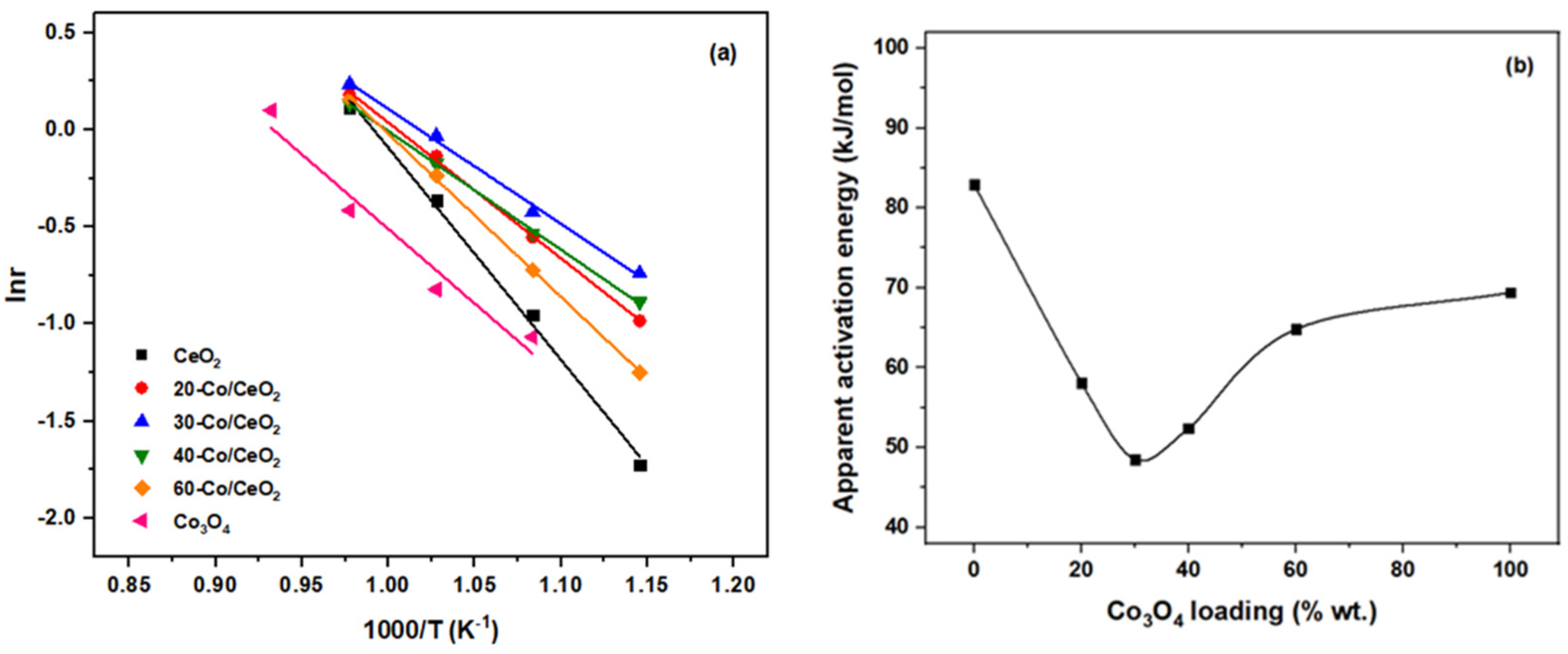
2.3. Apparent Activation Energies

For the approximate estimation of apparent activation energies, the differential method of analysis was followed. The possible contribution of internal mass transport phenomena was disregarded by means of the Weisz–Prater criterion (vide supra); thus, the measured apparent reaction rates were considered to be practically ascribed to the intrinsic reactivity of the catalysts. Therefore, the Arrhenius plots and the calculated activation energy values for all x-Co/CeO2 catalysts are shown in Figure 6a and Figure 6b, respectively. The superior performance of the 30-Co/CeO2 catalyst is again evident in terms of the apparent activation energy since it exhibits the lowest apparent activation energy value among all samples. Equally importantly, the binary cobalt oxide–ceria samples are associated with lower apparent activation energy values compared to the bare cobalt oxide and ceria, providing additional evidence of the beneficial role of the co-presence of cobalt oxide and ceria phases, which is also reflected in their catalytic activity (Figure 4).
A more meaningful assessment of the apparent activation energy values calculated in this study cannot be made since, to the best of our knowledge, this is the first time that such values have been reported in the literature for H2 production through the decomposition of H2S in extreme H2O excess conditions. In any case, and in order to better showcase the beneficial synergistic role of the as-prepared cobalt oxide–ceria catalysts, the apparent activation energies for the H2S decomposition reaction under both dry and wet conditions in the absence of catalysts were calculated (Arrhenius plots not shown for brevity). Specifically, apparent activation energy values equal to 124 and 137 kJ/mol were calculated for the non-catalytic thermal H2S decomposition in the presence and absence of water, respectively. Not unexpectedly, these values are substantially higher compared to the respective values for all the employed catalysts and especially for the 30-Co/CeO2 sample (Figure 6b). This finding showcases the significant role of catalysts, which enhance hydrogen production by offering a reaction pathway associated with a substantially decreased activation energy compared to the thermal-induced and gas-phase H2S decomposition.
Also, with regards to the activation energy for the reaction of H2S decomposition under dry and wet conditions for the optimum sample, i.e., 30-Co/CeO2 (see Figure 5), the values were calculated to equal 66 and 49 kJ/mol, respectively. Therefore, in comparison with the respective values obtained in catalyst-free experiments (i.e., 137 and 124 kJ/mol in the absence and presence of H2O, respectively), it is evident that the 30-Co/CeO2 sample remarkably modifies the H2S decomposition reaction pathway in the presence of water, as it decreases the apparent activation energy by a factor of 2.5. At the same time, the effect is less prominent under dry reaction conditions since the apparent activation energy in the presence of 30-Co/CeO2 catalyst is decreased by a factor of 2.0 compared to the blank experiments. In all, and although the present results are not derived through a dedicated kinetic analysis, the obtained values can be considered as a reference point that can be used for comparison purposes. Therefore, they need to be refined and rigorously calculated in future work employing a more detailed kinetic methodology, also taking into account the reversibility of the reaction.

2.4. Stability Tests

Motivated by the superior H2S decomposition performance of 30-Co/CeO2 under H2O excess conditions, short-term (10 h) stability experiments were also carried out to assess its lifetime characteristics (Figure 7). Specifically, the H2 production rate was continuously monitored at T = 850 °C as a function of time on stream. The fresh catalyst was first heated up to 850 °C (3 °C/min) under pure Ar atmosphere, kept at this temperature for 1 hr, and then at t = 0 min, the standard feed mixture used in the activity experiments (1 v/v% H2S–90 v/v% H2O, balanced with Ar), was introduced into the reactor. Interestingly, H2 production is continuously increased for the first ca. 4 h and then stabilized to a steady-state value of ca. 2.1 μmol∙g−1∙s−1. This value is similar to that obtained in the activity experiments and remained constant until the end of the experiment.
In an attempt to clarify whether the initial activation period for the 30-Co/CeO2 catalyst is associated with the in situ sulfidation or reduction of the sample during the reaction, two additional short-term (10 h) stability experiments were carried out employing the same catalyst at different initial states. In particular, prior to the experiment, the “untreated” 30-Co/CeO2 was subjected at 850 °C to a gas stream of either 1 v/v% H2S–90 v/v% H2O for 10 h or 10 v/v% H2/Ar for 1 h in order to obtain the “sulfided” and “reduced” samples, respectively. Both the “sulfided” and “reduced” catalysts were subsequently tested under the standard reaction conditions (1 v/v% H2S–90 v/v% H2O, balance with Ar), and their hydrogen production rate profiles vs. time on stream were compared with the “untreated” sample.
The comparison between the different pretreated catalysts revealed the remarkable behavior of the “sulfided” catalyst. It was observed that the initial activation period of approximately 4 h of the “untreated” 30-Co/CeO2 catalyst is reduced to less than 1.5 h for the “sulfided” sample. On the other hand, the “reduced” catalyst also demonstrated a decreased activation period (ca. 2 h) compared to the untreated material, but obviously higher compared to the “sulfided” sample.
In this point, it is worth pointing out the key role of chemisorption in the H2S decomposition process and in the observed transient nature of hydrogen generation in this work (Figure 7). Elsewhere, on a series of well-defined rhodium crystals [59], it was found that H2S adsorption on clean Rh(100) surfaces results in very rapid initial adsorption, followed by a very slow approach to saturation. This was followed by an increase in the surface S/Rh ratio, ascribed to the decomposition of H2S. Even more importantly, H2 desorption follows the same trend as the S/Rh ratio, showcasing the importance of progressive in situ sulfidation. Moreover, in a more recent study examining several transition metal sulfide catalysts [60], it was shown that at higher temperatures, the reaction could proceed under a quasi-steady state, where H2S conversion and H2 yield remain almost constant over elevated time on stream. Furthermore, a direct correlation between the amount of the released H2 and sulfur was disclosed.
In light of the present findings, it can be deduced that the progressive activation is mainly due to the in situ sulfidation of the catalyst under the reaction atmosphere and, to a lesser extent, to H2 reduction. This is better demonstrated by calculating the absolute hydrogen production (in mmol) during the activation period for each sample via the integration of the hydrogen production rate curve over the activation step. Indeed, the respective values for the “untreated”, “reduced”, and “sulfided” catalysts are equal to 288, 336, and 376 mmol H2/g, respectively, demonstrating the pronounced effect of sulfidation in the total hydrogen production. In all cases (“untreated”, “sulfided”, and “reduced”), the H2 production rate attained a stable value after a certain time period, reaching values similar to those obtained in the activity experiments and remaining stable until the end of the 10 h duration test. These findings clearly revealed the pronounced effect of in situ sulfidation, and to a lesser extent reduction, processes towards the progressive activation of cobalt oxide–ceria catalysts. Notably, irrespective of the catalyst’s initial state, all samples reach the same steady state, exhibiting a remarkably stable performance after a certain time. The beneficial effect of H2S during the course of the reaction between H2S and H2O is also worth noticing, in complete contrast to the poisoning effect of H2S in several catalytic processes [61,62,63]. Similar observations on the positive effect of sulfidation have been reported elsewhere [64].

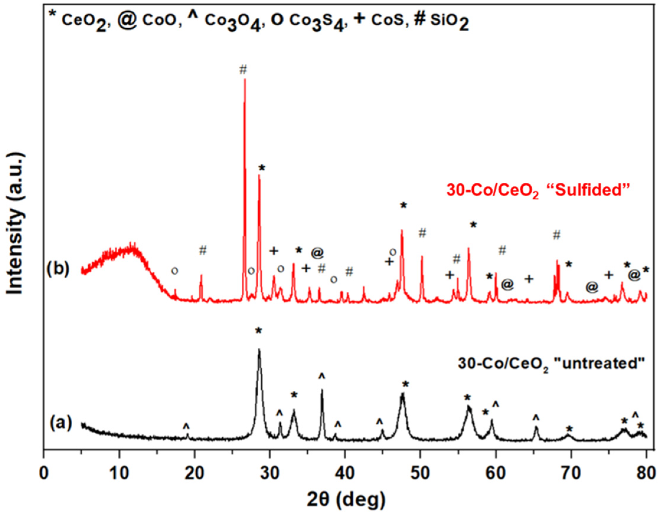
2.5. Spent Catalysts Characterization

In order to gain insight into the impact of the reaction conditions on the textural, structural, and surface features of the employed catalysts and to reveal possible structure-performance relationships, a complementary characterization study employing BET, XRD, SEM, and sulfur elemental analysis, prior (“untreated”) and after (“sulfided”) the stability experiments, was carried out. In terms of the textural characteristics, it is worth noticing that catalyst exposure to reaction conditions results in an almost complete collapse of the pore structure; the BET surface area and the pore volume of the “sulfided” catalyst decreased to about 2.4 m2/g and 0.04 cm3/g from 44.9 m2/g and 0.21 cm3/g of the “untreated” 30-Co/CeO2 catalyst, respectively. Coupled with the excellent activity and stability performance of the “sulfided” catalyst, the deterioration of its porous structure clearly implies that the catalytic activity is practically independent of the textural properties.
The structural modifications induced under reaction conditions were revealed by means of XRD studies. Figure 8 depicts the XRD patterns of the “untreated” and “sulfided” catalysts. It is evident that new crystal structures were formed during the reaction, which were absent from the “untreated” samples. In particular, the XRD pattern of the “untreated” sample presents reflections that correspond to the Co3O4 and CeO2 oxides, implying no chemical transformations or interactions between the parent oxides up to 600 °C (calcination temperature). However, the XRD pattern of the “sulfided” catalyst is completely different; the formation of new crystalline cobalt sulfide phases, i.e., Co3S4 and CoS, was clearly identified, verifying the in situ sulfidation of the catalyst under reaction conditions.
Surface modifications of the catalysts were further investigated by SEM/EDS analysis. Micrographs of the “untreated” and “sulfided” catalysts are presented at different magnifications in Figure 9. By comparing the SEM images of the “untreated” (Figure 9A,B) and “sulfided” (Figure 9C,D) samples, it is clear that the latter catalyst has undergone significant morphological modifications, leading to the formation of new phases, as a result of its exposure in H2S/H2O mixture at high temperatures. In particular, the formation of cobalt sulfide phases of polygon-like shape and cerium oxide particles of sponge-like morphology were revealed. Moreover, the average size of the cobalt-containing particles of the “sulfided” catalyst notably increased compared to the “untreated” catalyst, implying sintering under reaction conditions, in compliance with the above-discussed XRD and BET results.
In complete agreement with the identification of cobalt sulfide phases, a significant amount of sulfur (both in the form of elemental sulfur and in S-containing phases) was detected by sulfur elemental analysis of the “sulfided” sample (6.5 wt.%). However, this amount was approximately half compared to the elemental sulfur detected on the same sample when exposed to 1 v/v% H2S balanced with an Ar feed mixture for 10 h (13.1 wt.%). The considerably lower amount of elemental sulfur in the case of wet conditions is most probably ascribed to the formation of sulfur-containing gaseous products, predominantly SO2, as dictated by Equation (1). Notably, the relevant elemental mapping (not shown) demonstrated that sulfur formation and deposition was preferentially favored in the vicinity of Co-rich areas instead of CeO2-rich regions.
In view of the above findings, the already established superiority of the 30-Co/CeO2 catalyst for the H2S decomposition reaction under extremely wet conditions (90 v/v% H2O) should be mainly related to the in situ sulfidation of cobalt species (i.e., Co3O4 to Co3S4 and CoS), during its exposure to the reaction atmosphere. The previous analysis has clearly shown that during the catalytic decomposition of H2S in the presence of H2O, the 30-Co/CeO2 catalyst demonstrates the optimum activity performance and, at the same time, a remarkably stable behavior. It should be therefore deduced that the produced elemental sulfur is not simply deposited on the catalyst surface but strongly interacts with the catalyst counterparts to create new active and stable phases. These promising findings could pave the way for the development of active and stable materials to be applied as heterogeneous catalysts for the thermocatalytic decomposition of H2S in the presence of excess steam or as anode electrodes in H2S splitting proton-conducting solid electrolyte electrochemical membrane reactors for the efficient management of H2S emissions toward carbon-free hydrogen production.

3. Materials and Methods

3.1. Materials Preparation

A series of Co3O4/CeO2 supported catalysts at different cobalt loadings (0, 20, 30, 40, 60, and 100 wt.%) was synthesized via the wet impregnation technique. The as-prepared catalysts are henceforth denoted as x-Co/CeO2 for simplicity, with x referring to the weight percentage of Co in the composite materials. The synthetic protocol followed has been described in detail elsewhere [46]. In brief, the ceria-supported cobalt oxide catalysts were prepared by impregnation of an aqueous solution with appropriate concentrations of cobalt nitrate onto the calcined CeO2 support. The resulting solutions were subsequently heated under continuous stirring and then dried at 100 °C overnight. Finally, the obtained dried samples were calcined in air at 600 °C for 2 h using a heating rate of 5 °C/min.

3.2. Materials Characterization

The textural, structural, and morphological characteristics of bare oxides and as-prepared cobalt oxide/ceria catalysts were determined by means of BET, XRD, and SEM/EDX methods, as previously described in detail [43]. The elemental analysis of sulfur content was conducted according to UOP 703 method on a “CHN-800” elemental analyzer (LECO Corporation, St. Joseph, MI, USA).

3.3. Catalytic Evaluation

The experimental apparatus employed for the H2S decomposition catalytic studies under excess H2O conditions has been described in our previous work [46] and is graphically represented in Figure 10. In particular, the experimental setup is comprised of the feed, reaction, and analysis sections. The feedstock system includes the 10 v/v% H2S/Ar (Air Liquide Hellas, Athens, Greece) and pure Ar (99.998 v/v%, Linde Hellas, Sindos, Greece) high-pressure gas cylinders, the corresponding mass flow controllers (Brooks Instruments, Hatfield, Montgomery County, PA, USA) with a range of 0–20 cm3/min for the H2S/Ar mixture and 0–100 cm3/min for Ar at an accuracy of 1% and a digital bubble flow meter (Agilent Optiflow 520, Santa Clara, CA, USA) to regulate and monitor the volumetric gas flow rates, an HPLC 305 Pump (GILSON, Middleton, WI, USA) with a flow range between 0.14–25 cm3/min and an accuracy of 0.001 cm3/min to control the doubly distilled liquid H2O supply into the system, the preheater for steam generation at 130 °C and the heated stainless steel pipelines to provide the desired reactant mixture to the reactor, controlled at 130 °C by a K-type thermocouple. Appropriate flows of pure Ar and 10 v/v% H2S/Ar were mixed with steam derived by a liquid water supply of ca. 0.05 cm3/min so as to obtain the desired reactants feed mixture of 1 v/v% H2S and 90 v/v% H2O, balanced in Ar.
A typical quartz U-tube fixed bed reactor with an internal diameter of 9.6 mm was employed for the activity and stability of H2S decomposition experiments at excess H2O conditions. In each test, the catalyst bed consisted of a mixture of 250 mg catalyst and 250 mg quartz, both in powder form, resulting in a bed volume of ~0.45 cm3. Catalytic experiments were elaborated at atmospheric pressure and total feed rate equal to 100 cm3/min, corresponding to a GHSV of ~13,300 h−1.
The analysis of the produced hydrogen was carried out by means of a gas chromatograph (Shimadzu 14B, Kyoto, Japan) involving a thermal conductivity detector (TCD) and a molecular sieve 5A separation column. Prior to gas analysis, the reactor effluent gas mixture was flowing through a sulfur scrubber involving an aqueous KOH solution for the removal of any S-containing species.
During the catalytic activity tests, the temperature was increased at intervals of 50 °C, and the reaction was carried out in the temperature range of 550–850 °C. At the initial temperature of 550 °C, the system was left to stabilize for more than 4 h, and then for each temperature step, the system was allowed to reach a steady state (~1 h) before the effluent gas analysis was performed. Short-term stability tests were also carried out isothermally at 850 °C, where the hydrogen production rate was continuously monitored. For comparison purposes, blank experiments (without catalyst) were also carried out under specified reaction conditions. In the present work, the catalytic performance of the Co3O4/CeO2 mixed oxide samples is expressed in terms of hydrogen production rate (μmol H2∙g−1·s−1), calculated by the following equation (Equation (3)):
r H 2   ( μ mol   H 2   ·   g 1   ·   s 1 ) = 10 6   ·   F out   ·   [ H 2 ] out 60   ·   V M   ·   g cat
where Fout (cm3/min) is the reactor outlet flowrate, [H2]out is the molar fraction of hydrogen at the reactor outlet, VM (cm3/mol) is the molar volume of hydrogen at 1 bar and 25 °C, equal to 24,465 cm3/mol, and gcat is the catalyst mass. In addition, H2S conversion under dry reaction conditions (i.e., absence of excess H2O) was estimated on the basis of the following expression (Equation (4)):
X H 2 S   ( % ) = moles   of   produced   H 2   at   the   outlet H 2 S   moles   at   the   inlet   · 100  
Moreover, thermodynamic equilibrium values were calculated using an RGibbs block in Aspen Plus software. The components involved in the simulation were elemental sulfur, H2S, H2O, SO2, H2, SO3, O2, and Ar, and their thermophysical properties were obtained by applying the Peng-Robinson equation of state.

4. Conclusions

In the present work, the H2S decomposition activity of a series of Co3O4/CeO2 catalysts with variable cobalt loadings (0–100 wt.%) was evaluated toward carbon-free hydrogen production under extremely harsh reaction conditions employing a feed mixture comprising of 1 v/v% H2S and 90 v/v% H2O at high temperatures (550–850 °C) and atmospheric pressure. Furthermore, the analysis of the experimental results is accompanied and corroborated by thermodynamic calculations in order to gain insight into the beneficial effect of steam addition on the production rate of H2. It was revealed that the 30 wt.% Co3O4/CeO2 catalyst demonstrated the optimum activity and the lower apparent activation energy, followed by remarkable stability. Notably, Co3O4/CeO2 catalysts outperform bare ceria and cobalt oxide under wet conditions, implying a synergistic cobalt oxide–ceria interaction towards higher H2 production rates via H2S steam reforming. The enhancement in the production of hydrogen was also assessed by comparing the performance of the optimum 30-Co/CeO2 catalyst under dry and water-excess reaction conditions. Notably, significant augmentation in the H2 production rate was disclosed in the presence of steam.
Equally importantly, the key role of in situ sulfidation was revealed in stability tests over 30-Co/CeO2. Intriguingly, the pretreatment of the sample with the reacting H2S-H2O-Ar mixture (“sulfided”) led to the formation of active cobalt sulfide phases that allowed the system to faster reach steady state compared to the “untreated” and “reduced” sample. A complementary characterization study over both “untreated” and “sulfided” samples revealed the complete collapse of pore structure after catalysts exposure to reaction conditions, followed, however, by the formation of new cobalt sulfided phases, such as Co3S4 and CoS, which could be considered responsible for the excellent performance and stable behavior of the as-prepared cobalt oxide–ceria catalysts.

Author Contributions

Conceptualization, T.K. and G.E.M.; methodology, T.K.; software, G.V.; validation, G.V., G.E.M. and M.K.; formal analysis, G.V. and M.K.; investigation, T.K. and G.V.; resources, G.E.M.; data curation, G.E.M. and M.K.; writing—original draft preparation, T.K.; writing—review and editing, G.V., G.E.M. and M.K.; visualization, G.V.; supervision, G.E.M. and M.K.; project administration, G.E.M.; funding acquisition, G.E.M. All authors have read and agreed to the published version of the manuscript.

Funding

The work was performed within the frame of the joint program Black-Sea ERA.NET under the FP-7 initiative of the European Commission and funded by the Greek General Secretariat for Research and Technology GSRT (grant No. 11BS_10_28) and the project “Development of New Innovative Low Carbon Footprint Energy Technologies to Enhance Excellence in the Region of Western Macedonia” (MIS 5047197) which is implemented under the Action “Reinforcement of the Research and Innovation Infrastructure”, funded by the Operational Programme “Competitiveness, Entrepreneurship and Innovation” (NSRF 2014–2020) and co-financed by Greece and the European Union (European Regional Development Fund).

Data Availability Statement

Not applicable.

Conflicts of Interest

The authors declare no conflict of interest.

References

  1. IPCC. Climate Change 2021—The Physical Science Basis; Cambridge University Press: Cambridge, UK, 2021. [Google Scholar]
  2. Hulme, M. 1.5 °C and Climate Research after the Paris Agreement. Nat. Clim. Chang. 2016, 6, 222–224. [Google Scholar] [CrossRef] [Green Version]
  3. Depledge, J.; Saldivia, M.; Peñasco, C. Glass Half Full or Glass Half Empty?: The 2021 Glasgow Climate Conference. Clim. Policy 2022, 22, 147–157. [Google Scholar] [CrossRef]
  4. Capurso, T.; Stefanizzi, M.; Torresi, M.; Camporeale, S.M. Perspective of the Role of Hydrogen in the 21st Century Energy Transition. Energy Convers. Manag. 2022, 251, 114898. [Google Scholar] [CrossRef]
  5. Mac Dowell, N.; Sunny, N.; Brandon, N.; Herzog, H.; Ku, A.Y.; Maas, W.; Ramirez, A.; Reiner, D.M.; Sant, G.N.; Shah, N. The Hydrogen Economy: A Pragmatic Path Forward. Joule 2021, 5, 2524–2529. [Google Scholar] [CrossRef]
  6. Dincer, I.; Acar, C. Smart Energy Solutions with Hydrogen Options. Int. J. Hydrogen Energy 2018, 43, 8579–8599. [Google Scholar] [CrossRef]
  7. Yue, M.; Lambert, H.; Pahon, E.; Roche, R.; Jemei, S.; Hissel, D. Hydrogen Energy Systems: A Critical Review of Technologies, Applications, Trends and Challenges. Renew. Sustain. Energy Rev. 2021, 146, 111180. [Google Scholar] [CrossRef]
  8. International Energy Agency. Global Hydrogen Review 2021; International Energy Agency: Paris, France, 2021. [Google Scholar]
  9. Hermesmann, M.; Müller, T.E. Green, Turquoise, Blue, or Grey? Environmentally Friendly Hydrogen Production in Transforming Energy Systems. Prog. Energy Combust. Sci. 2022, 90, 100996. [Google Scholar] [CrossRef]
  10. Younas, M.; Shafique, S.; Hafeez, A.; Javed, F.; Rehman, F. An Overview of Hydrogen Production: Current Status, Potential, and Challenges. Fuel 2022, 316, 123317. [Google Scholar] [CrossRef]
  11. Nnabuife, S.G.; Ugbeh-Johnson, J.; Okeke, N.E.; Ogbonnaya, C. Present and Projected Developments in Hydrogen Production: A Technological Review. Carbon Capture Sci. Technol. 2022, 3, 100042. [Google Scholar] [CrossRef]
  12. Kayfeci, M.; Keçebaş, A.; Bayat, M. Hydrogen Production. In Solar Hydrogen Production; Elsevier: Amsterdam, The Netherland, 2019; pp. 45–83. [Google Scholar]
  13. Ishaq, H.; Dincer, I.; Crawford, C. A Review on Hydrogen Production and Utilization: Challenges and Opportunities. Int. J. Hydrogen Energy 2021, 47, 26238–26264. [Google Scholar] [CrossRef]
  14. De Crisci, A.G.; Moniri, A.; Xu, Y. Hydrogen from Hydrogen Sulfide: Towards a More Sustainable Hydrogen Economy. Int. J. Hydrogen Energy 2019, 44, 1299–1327. [Google Scholar] [CrossRef]
  15. Chan, Y.H.; Loy, A.C.M.; Cheah, K.W.; Chai, S.Y.W.; Ngu, L.H.; How, B.S.; Li, C.; Lock, S.S.M.; Wong, M.K.; Yiin, C.L.; et al. Hydrogen Sulfide (H2S) Conversion to Hydrogen (H2) and Value-Added Chemicals: Progress, Challenges and Outlook. Chem. Eng. J. 2023, 458, 141398. [Google Scholar] [CrossRef]
  16. Bahadori, A. Natural Gas Processing: Technology and Engineering Design; Elsevier: Amsterdam, The Netherlands, 2014; ISBN 9780080999715. [Google Scholar]
  17. Rodríguez, E.; Harvey, W.S.; Ásbjörnsson, E.J. Review of H2S Abatement Methods in Geothermal Plants. In Proceedings of the Thirty-Eighth Workshop on Geothermal Reservoir Engineering, Stanford, CA, USA, 11–13 February 2013. [Google Scholar]
  18. Deng, Q.; Wang, Q.; Liu, M.; Zhao, F. Geological Factors Controlling H2S in Coal Seams. In Mine Planning and Equipment Selection; Springer International Publishing: Cham, Switzerland, 2014; pp. 619–627. [Google Scholar]
  19. Corpas, F.J.; Palma, J.M. H2S Signaling in Plants and Applications in Agriculture. J. Adv. Res. 2020, 24, 131–137. [Google Scholar] [CrossRef] [PubMed]
  20. Jørgensen, B.B.; Findlay, A.J.; Pellerin, A. The Biogeochemical Sulfur Cycle of Marine Sediments. Front. Microbiol. 2019, 10, 849. [Google Scholar] [CrossRef] [PubMed]
  21. King, M.J.; Davenport, W.G.; Moats, M.S. Sulfuric Acid Manufacture: Analysis, Control and Optimization; Elsevier: Amsterdam, The Netherlands, 2013; ISBN 978-0-08-098220-5. [Google Scholar]
  22. Kaiser, M.J.; de Klerk, A.; Gary, J.H.; Hwerk, G.E. Petroleum Refining: Technology, Economics, and Markets; CRC Press: Boca Raton, FL, USA, 2019; ISBN 9780429188893. [Google Scholar]
  23. Wiheeb, A.D.; Shamsudin, I.K.; Ahmad, M.A.; Murat, M.N.; Kim, J.; Othman, M.R. Present Technologies for Hydrogen Sulfide Removal from Gaseous Mixtures. Rev. Chem. Eng. 2013, 29, 449–470. [Google Scholar] [CrossRef]
  24. Ghahraloud, H.; Farsi, M.; Rahimpour, M.R. Hydrogen Production through Thermal Decomposition of Hydrogen Sulfide: Modification of the Sulfur Recovery Unit To Produce Ultrapure Hydrogen. Ind. Eng. Chem. Res. 2018, 57, 14114–14123. [Google Scholar] [CrossRef]
  25. Palma, V.; Vaiano, V.; Barba, D.; Colozzi, M.; Palo, E.; Barbato, L.; Cortese, S. H2 Production by Thermal Decomposition of H2S in the Presence of Oxygen. Int. J. Hydrogen Energy 2015, 40, 106–113. [Google Scholar] [CrossRef]
  26. Burra, K.R.G.; Bassioni, G.; Gupta, A.K. Catalytic Transformation of H2S for H2 Production. Int. J. Hydrogen Energy 2018, 43, 22852–22860. [Google Scholar] [CrossRef]
  27. Jiang, G.; Zhang, X.; Zhang, F.; Liu, Z.; Wang, Z.; Hao, Z.; Lin, C. Efficient Recovery of Hydrogen and Sulfur Resources over Non-Sulfide Based LaFexAl12-XO19 Hexaaluminate Catalysts by H2S Catalytic Decomposition. Appl. Catal. B Environ. 2020, 263, 118354. [Google Scholar] [CrossRef]
  28. Linga Reddy, E.; Biju, V.M.; Subrahmanyam, C. Production of Hydrogen and Sulfur from Hydrogen Sulfide Assisted by Nonthermal Plasma. Appl. Energy 2012, 95, 87–92. [Google Scholar] [CrossRef]
  29. Dang, X.; Huang, J.; Kang, L.; Wu, T.; Zhang, Q. Research on Decomposition of Hydrogen Sulfide Using Nonthermal Plasma with Metal Oxide Catalysis. Energy Procedia 2012, 16, 856–862. [Google Scholar] [CrossRef] [Green Version]
  30. Zhang, B.; Bai, J.; Zhang, Y.; Zhou, C.; Wang, P.; Zha, L.; Li, J.; Simchi, A.; Zhou, B. High Yield of CO and Synchronous S Recovery from the Conversion of CO2 and H2S in Natural Gas Based on a Novel Electrochemical Reactor. Environ. Sci. Technol. 2021, 55, 14854–14862. [Google Scholar] [CrossRef] [PubMed]
  31. Yu, S.; Zhou, Y. Photochemical Decomposition of Hydrogen Sulfide. In Advanced Catalytic Materials-Photocatalysis and Other Current Trends; InTech: Rijeka, Croatia, 2016. [Google Scholar]
  32. Zaman, J.; Chakma, A. Production of Hydrogen and Sulfur from Hydrogen Sulfide. Fuel Process. Technol. 1995, 41, 159–198. [Google Scholar] [CrossRef]
  33. Chivers, T.; Lau, C. The Thermal Decomposition of Hydrogen Sulfide over Vanadium and Molybdenum Sulfides and Mixed Sulfide Catalysts in Quartz and Thermal Diffusion Column Reactors. Int. J. Hydrogen Energy 1987, 12, 235–243. [Google Scholar] [CrossRef]
  34. Kaloidas, V.; Papayannakos, N. Hydrogen Production from the Decomposition of Hydrogen Sulphide. Equilibrium Studies on the System H2S/H2/Si, (i = 1,…,8) in the Gas Phase. Int. J. Hydrogen Energy 1987, 12, 403–409. [Google Scholar] [CrossRef]
  35. Ipsakis, D.; Kraia, T.; Marnellos, G.E.; Ouzounidou, M.; Voutetakis, S.; Dittmeyer, R.; Dubbe, A.; Haas-Santo, K.; Konsolakis, M.; Figen, H.E.; et al. An Electrocatalytic Membrane-Assisted Process for Hydrogen Production from H 2 S in Black Sea: Preliminary Results. Int. J. Hydrogen Energy 2015, 40, 7530–7538. [Google Scholar] [CrossRef]
  36. Demirbas, A. Hydrogen Sulfide from the Black Sea for Hydrogen Production. Energy Sources Part A Recover. Util. Environ. Eff. 2009, 31, 1866–1872. [Google Scholar] [CrossRef]
  37. Ozturk, M.; Midilli, A.; Dincer, I. Effective Use of Hydrogen Sulfide and Natural Gas Resources Available in the Black Sea for Hydrogen Economy. Int. J. Hydrogen Energy 2021, 46, 10697–10707. [Google Scholar] [CrossRef]
  38. Ryann, A.; Perkins, N.J. The Black Sea: Dynamics, Ecology, and Conservation; Nova Science Publishers, Inc.: London, UK, 2011. [Google Scholar]
  39. Kraia, T.; Wachowski, S.; Vøllestad, E.; Strandbakke, R.; Konsolakis, M.; Norby, T.; Marnellos, G.E. Electrochemical Performance of Co3O4/CeO2 Electrodes in H2S/H2O Atmospheres in a Proton-Conducting Ceramic Symmetrical Cell with BaZr0.7Ce0.2Y0.1O3 Solid Electrolyte. Solid State Ionics 2017, 306, 31–37. [Google Scholar] [CrossRef] [Green Version]
  40. Petrov, K.; Baykara, S.Z.; Ebrasu, D.; Gulin, M.; Veziroglu, A. An Assessment of Electrolytic Hydrogen Production from H 2 S in Black Sea Waters. Int. J. Hydrogen Energy 2011, 36, 8936–8942. [Google Scholar] [CrossRef]
  41. Guldal, N.O.; Figen, H.E.; Baykara, S.Z. Perovskite Catalysts for Hydrogen Production from Hydrogen Sulfide. Int. J. Hydrogen Energy 2018, 43, 1038–1046. [Google Scholar] [CrossRef]
  42. Guldal, N.O.; Figen, H.E.; Baykara, S.Z. Production of Hydrogen from Hydrogen Sulfide with Perovskite Type Catalysts: LaMO3. Chem. Eng. J. 2017, 313, 1354–1363. [Google Scholar] [CrossRef]
  43. Lykaki, M.; Pachatouridou, E.; Iliopoulou, E.; Carabineiro, S.A.C.; Konsolakis, M. Impact of the Synthesis Parameters on the Solid State Properties and the CO Oxidation Performance of Ceria Nanoparticles. RSC Adv. 2017, 7, 6160–6169. [Google Scholar] [CrossRef] [Green Version]
  44. Konsolakis, M. The Role of Copper–Ceria Interactions in Catalysis Science: Recent Theoretical and Experimental Advances. Appl. Catal. B Environ. 2016, 198, 49–66. [Google Scholar] [CrossRef]
  45. Xu, Y.; Mofarah, S.S.; Mehmood, R.; Cazorla, C.; Koshy, P.; Sorrell, C.C. Design Strategies for Ceria Nanomaterials: Untangling Key Mechanistic Concepts. Mater. Horizons 2021, 8, 102–123. [Google Scholar] [CrossRef] [PubMed]
  46. Kraia, T.; Kaklidis, N.; Konsolakis, M.; Marnellos, G.E. Hydrogen Production by H2S Decomposition over Ceria Supported Transition Metal (Co, Ni, Fe and Cu) Catalysts. Int. J. Hydrogen Energy 2019, 44, 9753–9762. [Google Scholar] [CrossRef]
  47. Jha, A.; Jeong, D.W.; Lee, Y.L.; Nah, I.W.; Roh, H.S. Enhancing the Catalytic Performance of Cobalt Oxide by Doping on Ceria in the High Temperature Water-Gas Shift Reaction. RSC Adv. 2015, 5, 103023–103029. [Google Scholar] [CrossRef]
  48. Liu, Z.; Li, J.; Buettner, M.; Ranganathan, R.V.; Uddi, M.; Wang, R. Metal-Support Interactions in CeO2- and SiO2-Supported Cobalt Catalysts: Effect of Support Morphology, Reducibility, and Interfacial Configuration. ACS Appl. Mater. Interfaces 2019, 11, 17035–17049. [Google Scholar] [CrossRef]
  49. Varvoutis, G.; Lykaki, M.; Papista, E.; Carabineiro, S.A.C.; Psarras, A.C.; Marnellos, G.E.; Konsolakis, M. Effect of Alkali (Cs) Doping on the Surface Chemistry and CO2 Hydrogenation Performance of CuO/CeO2 Catalysts. J. CO2 Util. 2021, 44, 101408. [Google Scholar] [CrossRef]
  50. Díez-Ramírez, J.; Sánchez, P.; Kyriakou, V.; Zafeiratos, S.; Marnellos, G.E.; Konsolakis, M.; Dorado, F. Effect of Support Nature on the Cobalt-Catalyzed CO2 Hydrogenation. J. CO2 Util. 2017, 21, 562–571. [Google Scholar] [CrossRef]
  51. Parastaev, A.; Muravev, V.; Osta, E.H.; Kimpel, T.F.; Simons, J.F.M.; van Hoof, A.J.F.; Uslamin, E.; Zhang, L.; Struijs, J.J.C.; Burueva, D.B.; et al. Breaking Structure Sensitivity in CO2 Hydrogenation by Tuning Metal–Oxide Interfaces in Supported Cobalt Nanoparticles. Nat. Catal. 2022, 5, 11. [Google Scholar] [CrossRef]
  52. Liu, H.; Xu, S.; Zhou, G.; Xiong, K.; Jiao, Z.; Wang, S. CO2 Hydrogenation to Methane over Co/KIT-6 Catalysts: Effect of Co Content. Fuel 2018, 217, 570–576. [Google Scholar] [CrossRef]
  53. Al-Musa, A.; Al-Saleh, M.; Ioakeimidis, Z.C.; Ouzounidou, M.; Yentekakis, I.V.; Konsolakis, M.; Marnellos, G.E. Hydrogen Production by Iso-Octane Steam Reforming over Cu Catalysts Supported on Rare Earth Oxides (REOs). Int. J. Hydrogen Energy 2014, 39, 1350–1363. [Google Scholar] [CrossRef]
  54. Adesina, A.A.; Meeyoo, V.; Foulds, G. Thermolysis of Hydrogen Sulphide in an Open Tubular Reactor. Int. J. Hydrogen Energy 1995, 20, 777–783. [Google Scholar] [CrossRef]
  55. Shi, X.; Yu, Y.; Xue, L.; He, H. Effect of Sulfur Poisoning on Co3O4/CeO2 Composite Oxide Catalyst for Soot Combustion. Chinese J. Catal. 2014, 35, 1504–1510. [Google Scholar] [CrossRef]
  56. Lykaki, M.; Papista, E.; Kaklidis, N.; Carabineiro, S.; Konsolakis, M. Ceria Nanoparticles’ Morphological Effects on the N2O Decomposition Performance of Co3O4/CeO2 Mixed Oxides. Catalysts 2019, 9, 233. [Google Scholar] [CrossRef] [Green Version]
  57. Carabineiro, S.A.C.; Chen, X.; Konsolakis, M.; Psarras, A.C.; Tavares, P.B.; Órfão, J.J.M.; Pereira, M.F.R.; Figueiredo, J.L. Catalytic Oxidation of Toluene on Ce–Co and La–Co Mixed Oxides Synthesized by Exotemplating and Evaporation Methods. Catal. Today 2015, 244, 161–171. [Google Scholar] [CrossRef] [Green Version]
  58. Parastaev, A.; Muravev, V.; Huertas Osta, E.; van Hoof, A.J.F.; Kimpel, T.F.; Kosinov, N.; Hensen, E.J.M. Boosting CO2 Hydrogenation via Size-Dependent Metal–Support Interactions in Cobalt/Ceria-Based Catalysts. Nat. Catal. 2020, 3, 526–533. [Google Scholar] [CrossRef]
  59. Hegde, R.I.; White, J.M. Chemisorption and Decomposition of H2S on Rh(100). J. Phys. Chem. 1986, 90, 296–300. [Google Scholar] [CrossRef]
  60. Zagoruiko, A.; Mikenin, P. Decomposition of Hydrogen Sulfide into Elements in the Cyclic Chemisorption-Catalytic Regime. Catal. Today 2021, 378, 176–188. [Google Scholar] [CrossRef]
  61. Blanchard, J.; Achouri, I.; Abatzoglou, N. H 2 S Poisoning of NiAl2O4/Al2O3-YSZ Catalyst during Methane Dry Reforming. Can. J. Chem. Eng. 2016, 94, 650–654. [Google Scholar] [CrossRef]
  62. Dou, X.; Veksha, A.; Chan, W.P.; Oh, W.-D.; Liang, Y.N.; Teoh, F.; Mohamed, D.K.B.; Giannis, A.; Lisak, G.; Lim, T.-T. Poisoning Effects of H2S and HCl on the Naphthalene Steam Reforming and Water-Gas Shift Activities of Ni and Fe Catalysts. Fuel 2019, 241, 1008–1018. [Google Scholar] [CrossRef]
  63. Wachter, P.; Gaber, C.; Raic, J.; Demuth, M.; Hochenauer, C. Experimental Investigation on H2S and SO2 Sulphur Poisoning and Regeneration of a Commercially Available Ni-Catalyst during Methane Tri-Reforming. Int. J. Hydrogen Energy 2021, 46, 3437–3452. [Google Scholar] [CrossRef]
  64. Iqbal, S.; Amjad, A.; Javed, M.; Alfakeer, M.; Mushtaq, M.; Rabea, S.; Elkaeed, E.B.; Pashameah, R.A.; Alzahrani, E.; Farouk, A.-E. Boosted Spatial Charge Carrier Separation of Binary ZnFe2O4/S-g-C3N4 Heterojunction for Visible-Light-Driven Photocatalytic Activity and Antimicrobial Performance. Front. Chem. 2022, 10, 894. [Google Scholar] [CrossRef]
Figure 1. X-ray powder diffraction patterns of x-Co/CeO2 catalysts with a mass Co loading of 100% (a), 60% (b), 40% (c), 30% (d), 20% (e) and 0% (f). Data for (e,f) are taken from Ref. [46].
Catalysts 13 00504 g001
Figure 2. Left y-axis: Hydrogen production rate as a function of temperature and feedstock composition in the absence of catalyst (blank experiments). Right y-axis: Experimental and equilibrium H2S conversion values for the dry H2S decomposition reaction (green lines). Reaction conditions: P = 1 bar, Flowrate: 100 cm3/min.
Catalysts 13 00504 g002
Figure 3. Effect of H2O feed concentration on the thermodynamic H2S conversion at ambient pressure as a function of temperature in the (a) absence and (b) presence of inert Ar.
Catalysts 13 00504 g003
Figure 4. Hydrogen production rate as a function of temperature for x-Co/CeO2 catalysts. Reaction conditions: 1 v/v% H2S–90 v/v% H2O, balanced with Ar, P = 1 bar, Flowrate: 100 cm3/min, Catalyst mass = 250 mg, GHSV = 13,300 h−1.
Catalysts 13 00504 g004
Figure 5. Left y-axis: H2 production rate as a function of temperature for 30-Co/CeO2 and bare CeO2. Right y-axis: Experimental and equilibrium H2S conversion for the dry H2S decomposition reaction over 30-Co/CeO2 (green lines). Reaction conditions: P = 1 bar, Flowrate: 100 cm3/min, Catalyst mass = 250 mg, GHSV = 13,300 h−1.
Catalysts 13 00504 g005
Figure 6. Arrhenius plots (a) and apparent activation energy values (b) for the as-prepared x-Co/CeO2 catalysts. Reaction conditions: 1 v/v% H2S–90 v/v% H2O, balanced with Ar, P = 1 bar, Flowrate: 100 cm3/min, Catalyst mass = 250 mg, GHSV = 13,300 h−1.
Catalysts 13 00504 g006
Figure 7. Hydrogen production rate as a function of time on stream for the “untreated”, “sulfided” and “reduced” catalysts. Reaction conditions: 1 v/v% H2S–90 v/v% H2O, balanced with Ar, P = 1 bar, T = 850 °C, Flowrate: 100 cm3/min, Catalyst mass = 250 mg, GHSV = 13,300 h−1.
Catalysts 13 00504 g007
Figure 8. X-ray diffraction patterns of the (a) “untreated” and (b) “sulfided” catalysts. The “sulfided” catalyst was exposed for 10 h in a reaction mixture containing 1 v/v% H2S and 90 v/v% H2O, balanced in Ar, at T = 850 °C.
Catalysts 13 00504 g008
Figure 9. SEM images of the “untreated” (A,B), and “sulfided” (C,D), catalysts. The “sulfided” catalyst was exposed for 10 h in a reaction mixture containing 1 v/v% H2S–90 v/v% H2O, balanced in Ar, at T = 850 °C.
Catalysts 13 00504 g009
Figure 10. Schematic representation of the apparatus used in the catalytic experiments. Feed section: (1) (1a) 10 v/v% H2S/Ar cylinder, (1b) Pure Ar cylinder; (2) MFC: Mass Flow Controllers for H2S/Ar and Ar; (3) Doubly distilled liquid water pump; (4) Preheater for steam generation. Reaction section: (5) High-temperature furnace and U-tube quartz reactor; (6) Condenser; (7) Sulfur trap. Analysis section: (8) GC: Gas Chromatograph. PI: Pressure Indicator; FI: Flow Indicator; TE: Temperature Indicator; HE: Heat Exchanger. Adapted from Ref. [46].
Catalysts 13 00504 g010
Table 1. Textural and structural properties of bare oxides and x-Co/CeO2 catalysts.
SampleN2 PorosimetryXRD Analysis
BET Surface
Area (m2/g)
Pore Volume
(cm3/g)
Average Pore
Diameter (nm)
Crystal PhaseCrystallite
Size (nm)
CeO2 a71.50.2715.4CeO211.0
20-Co/CeO2 a33.40.13 CeO210.2
16.0Co3O437.7
30-Co/CeO244.90.21 CeO210.4
18.7Co3O437.9
40-Co/CeO228.40.10 CeO210.5
14.7Co3O441.7
60-Co/CeO215.10.07 CeO210.5
19.3Co3O442.2
Co3O42.90.01 Co3O450.7
17.8CoO52.7
a Data taken from Ref. [46].
Disclaimer/Publisher’s Note: The statements, opinions and data contained in all publications are solely those of the individual author(s) and contributor(s) and not of MDPI and/or the editor(s). MDPI and/or the editor(s) disclaim responsibility for any injury to people or property resulting from any ideas, methods, instructions or products referred to in the content.

