
Recent Strategies to Improve the Photocatalytic Efficiency of TiO2 for Enhanced Water Splitting to Produce Hydrogen

 ,
,  , and
, and
Abstract
1. Introduction
2. Hydrogen Production Methods
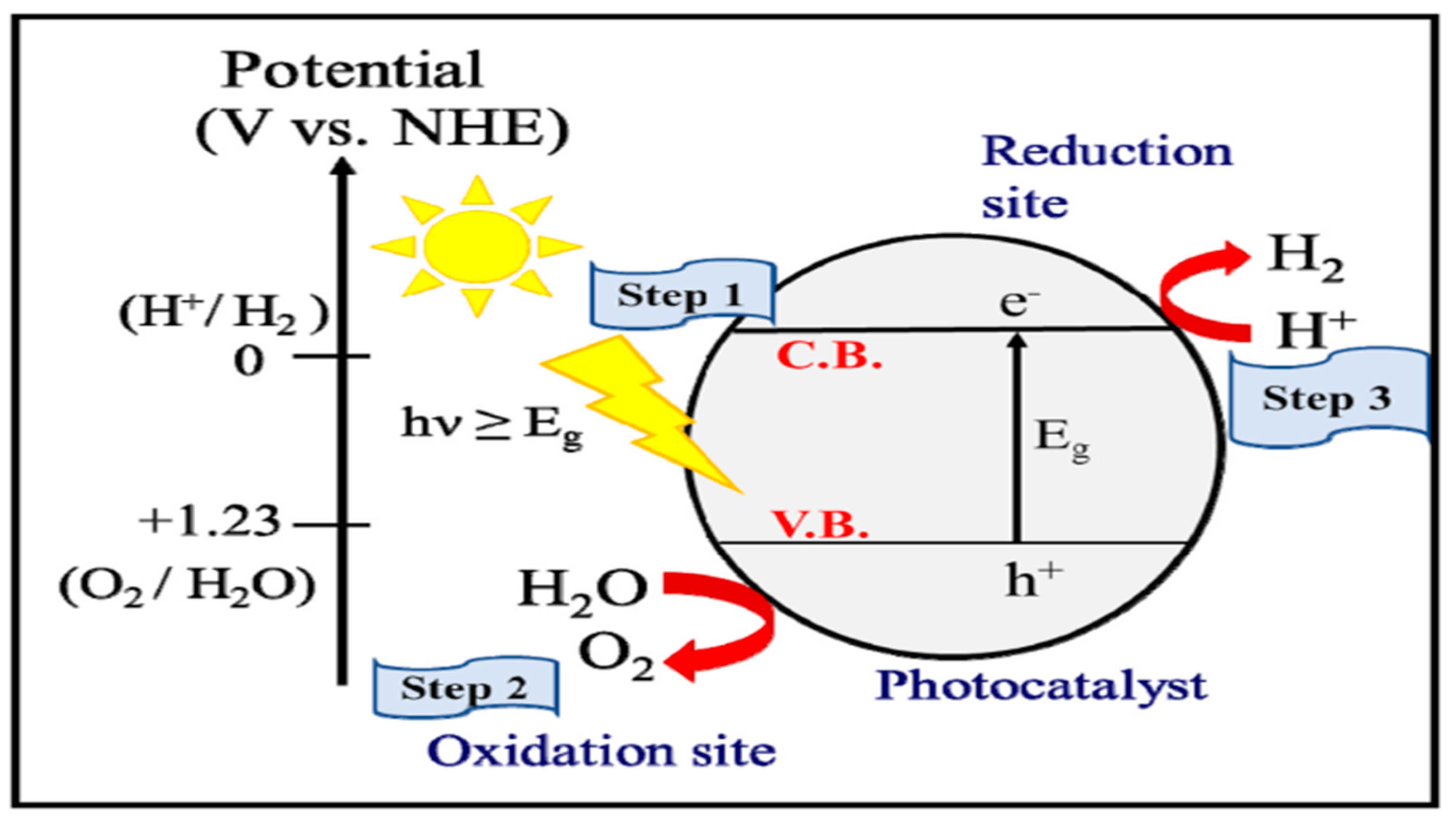
3. Mechanism of Photocatalytic Water Splitting
3.1. Types of Reactions
- Photochemical reactions;
- Photoelectrochemical reactions.
3.1.1. Photochemical Reactions
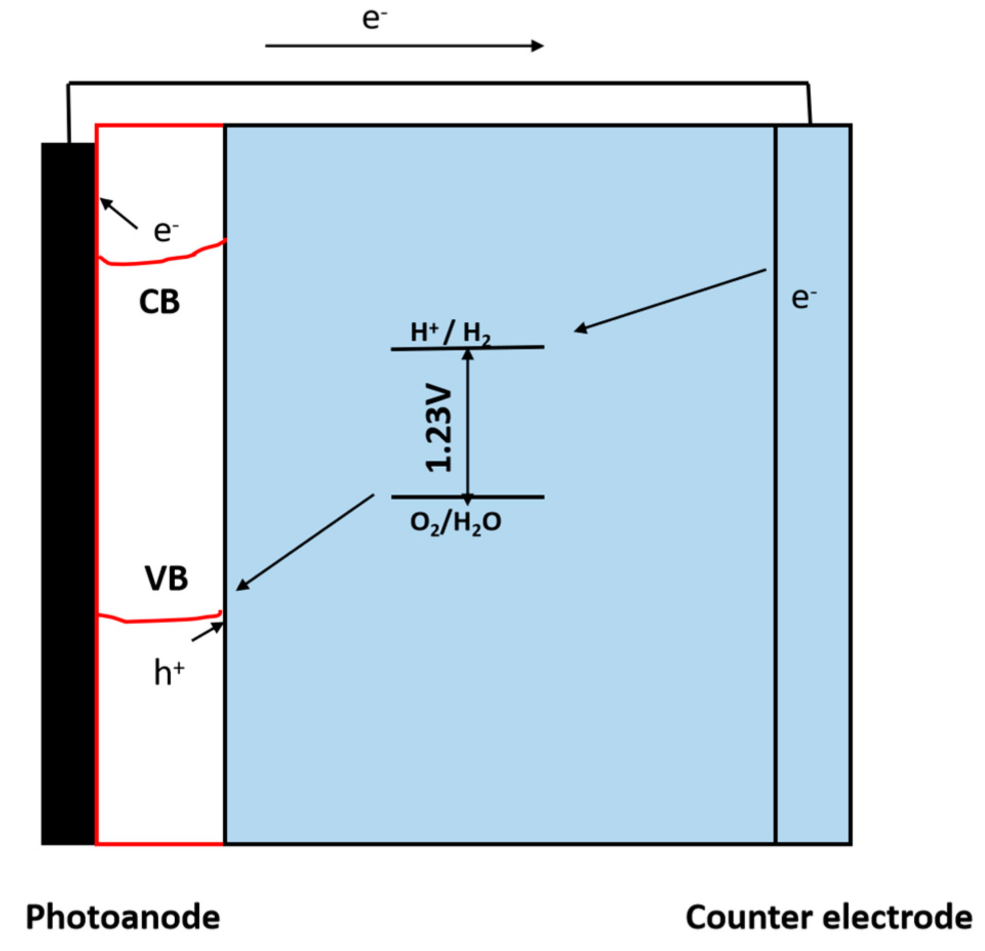
3.1.2. Photoelectrochemical (PEC) Reactions
Working Principle of Photoelectrochemical (PEC) Reaction
4. Desired Characteristic of the Material Used for PEC
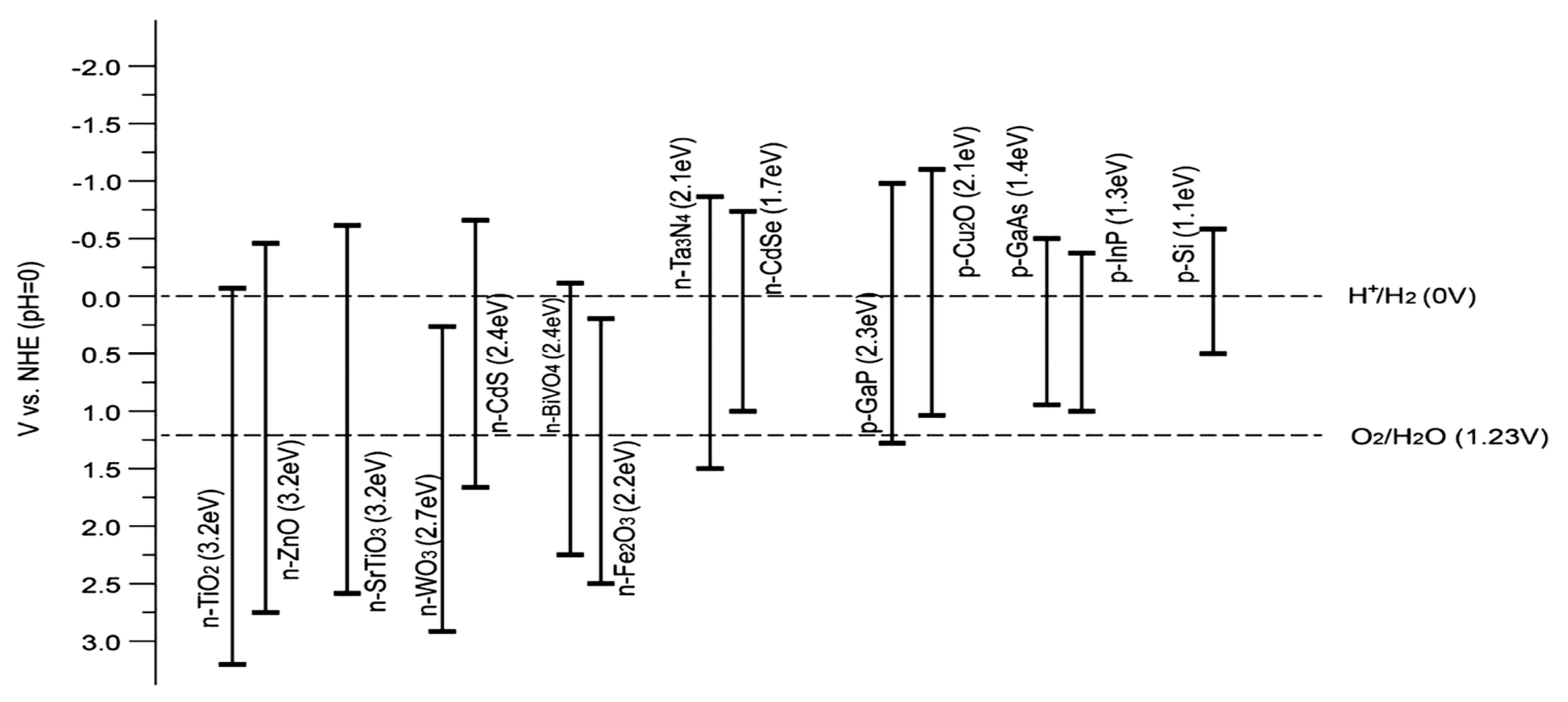
4.1. Adequate Band Locations and Bandgap Energy
4.2. Effective Separation and Movement of Charge Carriers within the Semiconductor
4.3. Stable and High Catalytic Activity
- Photocathodic materials
- Photoanodic materials
5. Electrolysis
5.1. Mechanism of Water Splitting in Alkaline Solutions
5.2. Ion-Exchange Membrane
6. Hydrogen Generation Electrolyzers
Types of Electrolyzers
7. Requirements for Efficient Working
8. Various Catalysts for Water Splitting
9. Titania for Water Splitting
9.1. Photocatalytic Water-Splitting Mechanisms for the Production of Hydrogen Using TiO2
9.2. Limitations of Solar Hydrogen Generation with TiO2
10. Strategies to Improve the Efficiency of the TiO2 Photocatalyst
10.1. Doping
10.1.1. Anionic Doping in TiO2
N-Doped TiO2
F-Doped TiO2
S-Doped TiO2
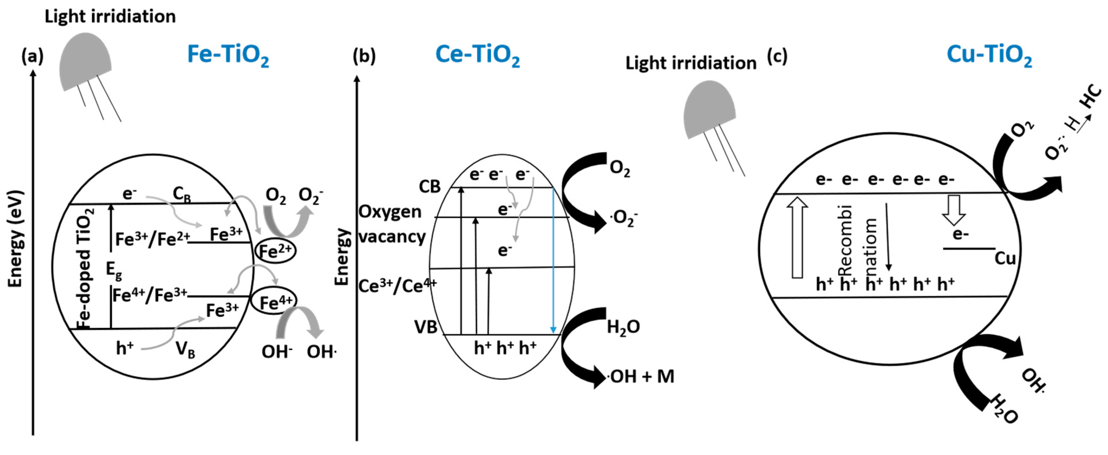
10.1.2. Cationic Doping
10.2. Sensitization of TiO2
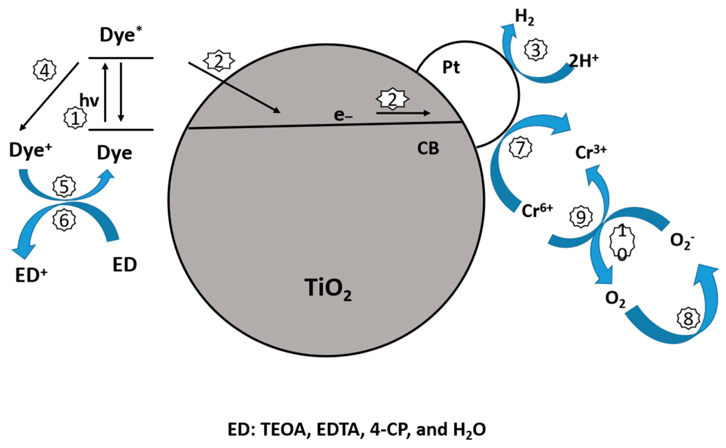
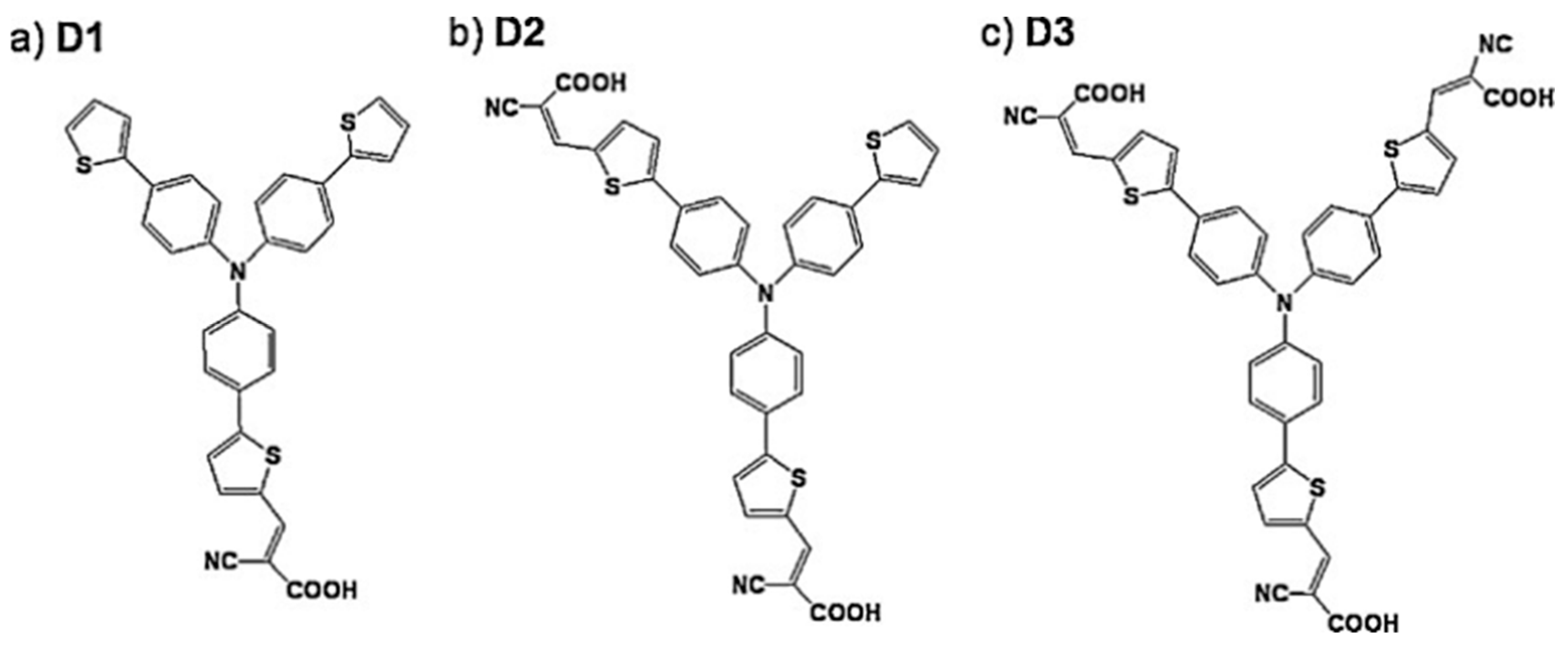
10.2.1. Dye Sensitization
10.2.2. Sensitization with Noble Metal Particles
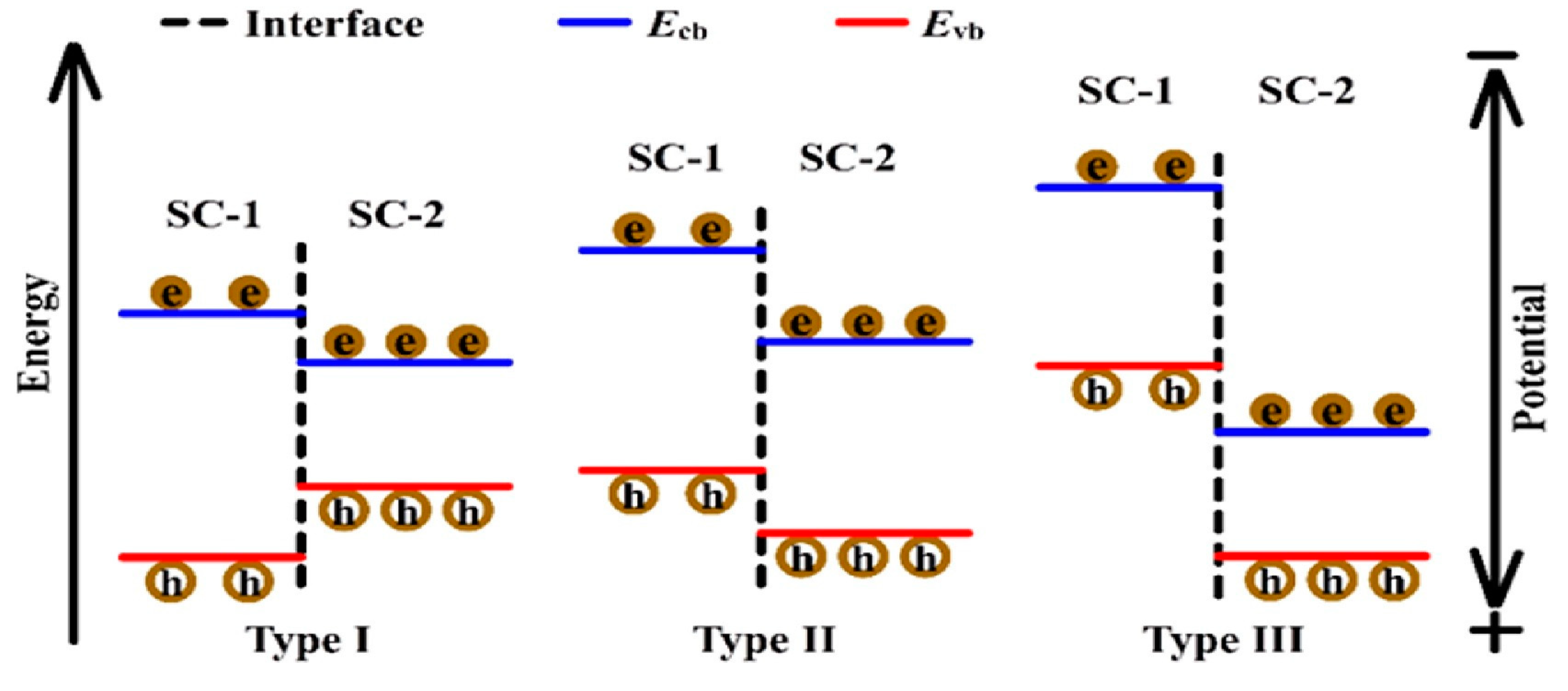
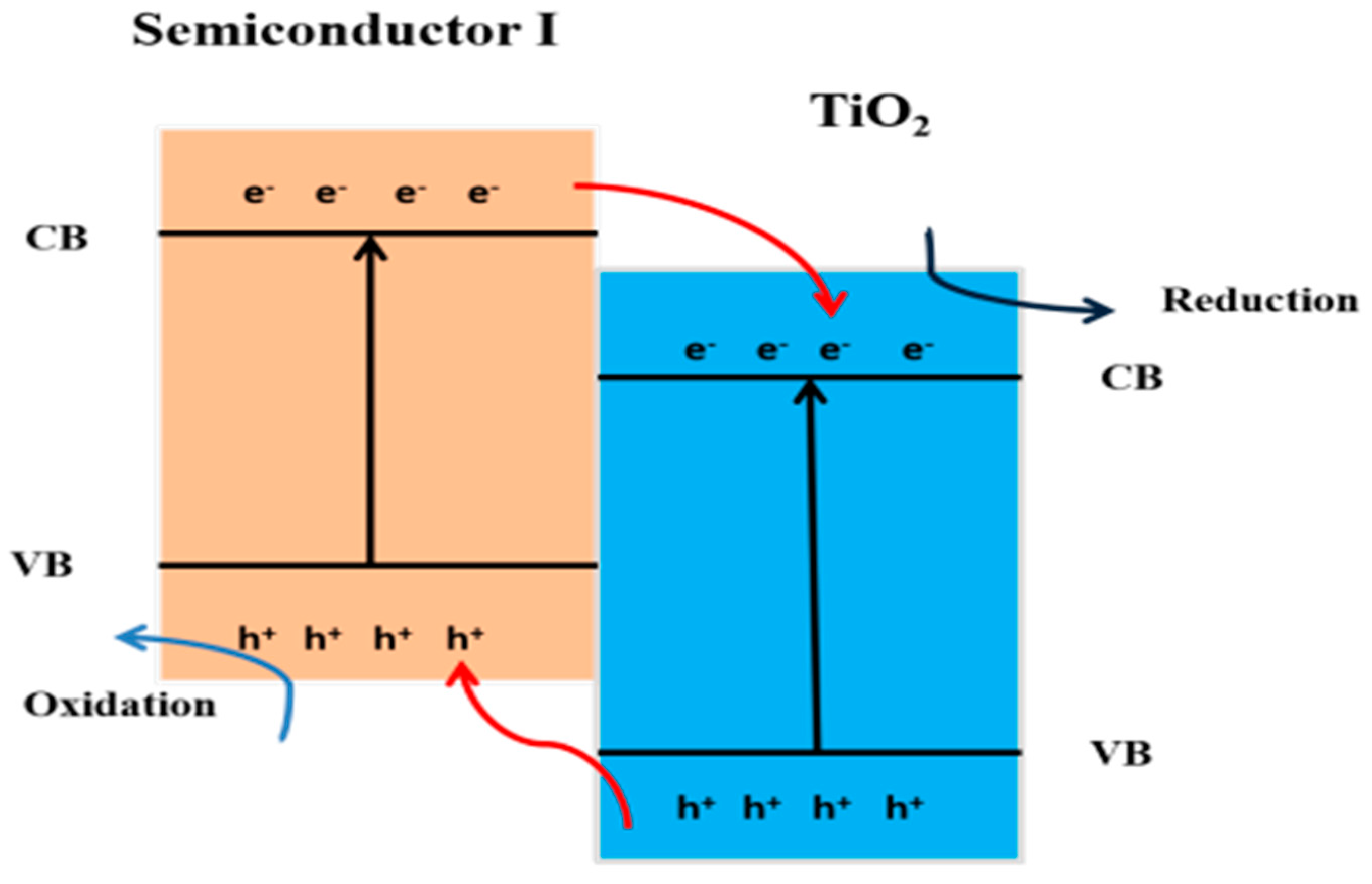
10.3. Heterojunction Construction
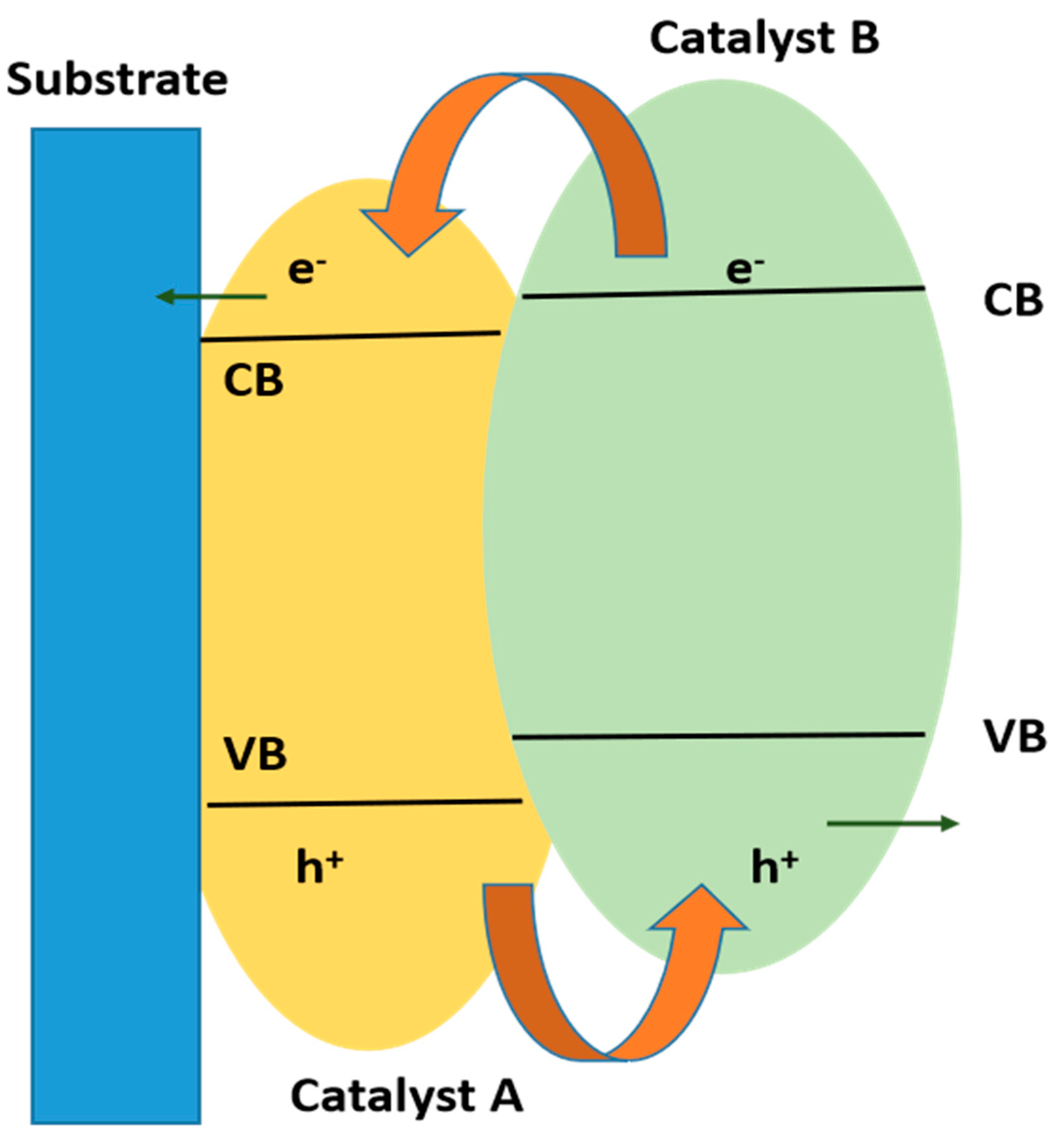
10.3.1. Type II Heterojunction
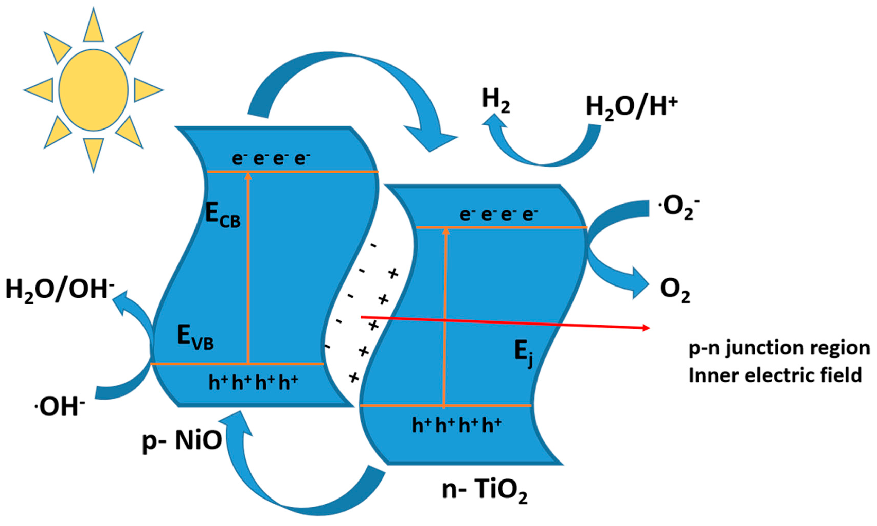
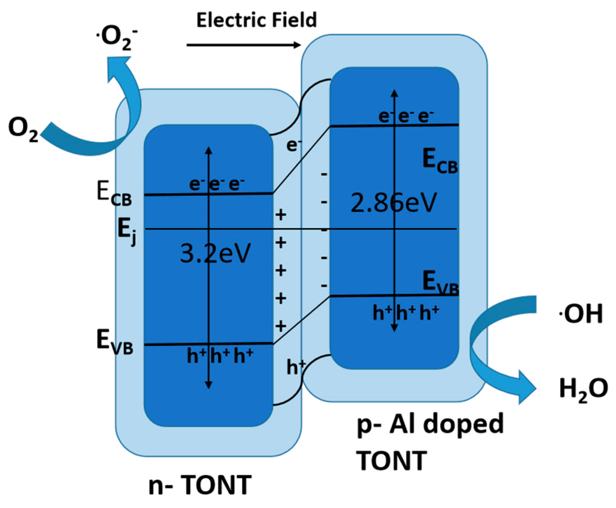
10.3.2. p-Type or n-Type
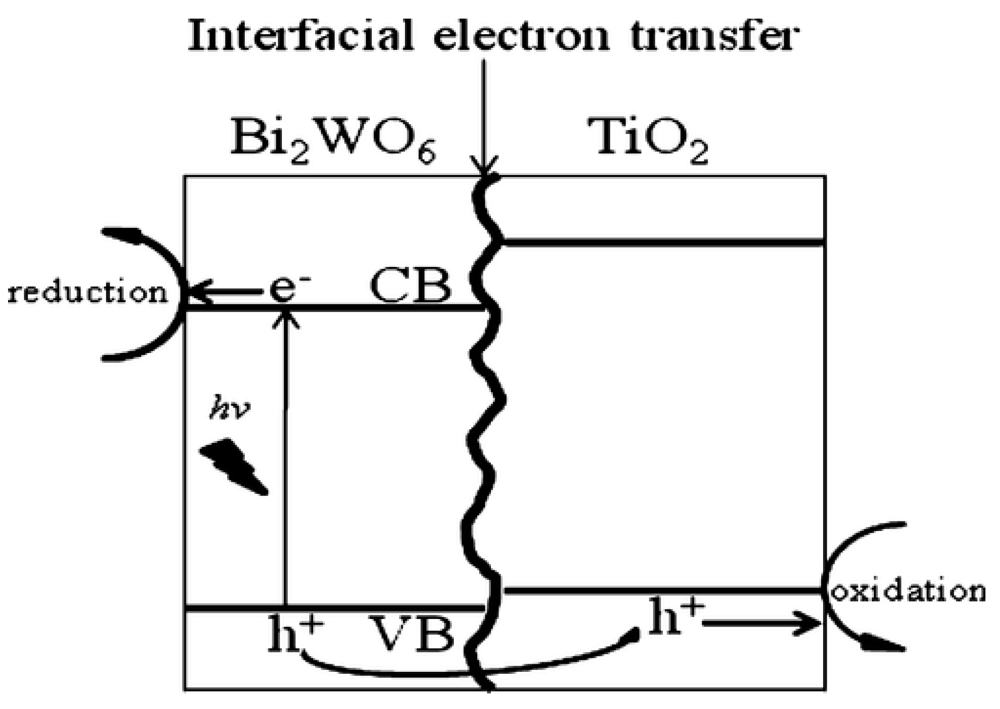
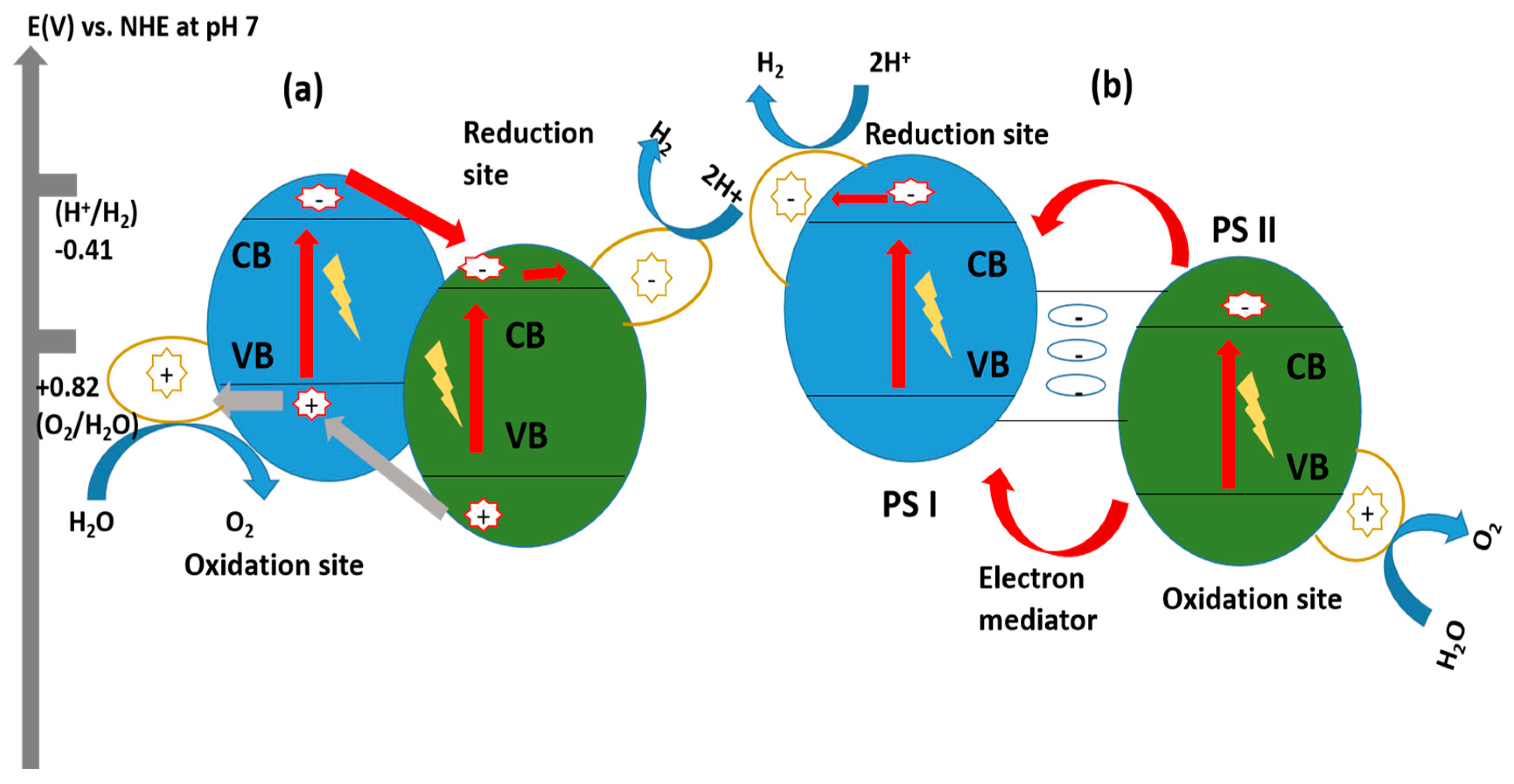
10.3.3. Z-Scheme Heterojunction
Z-Scheme System with Shuttle Redox Mediators

Direct Z-Scheme Hydrogen Production
10.4. Comparison of Type II Heterojunctions and Z-Scheme Heterojunctions
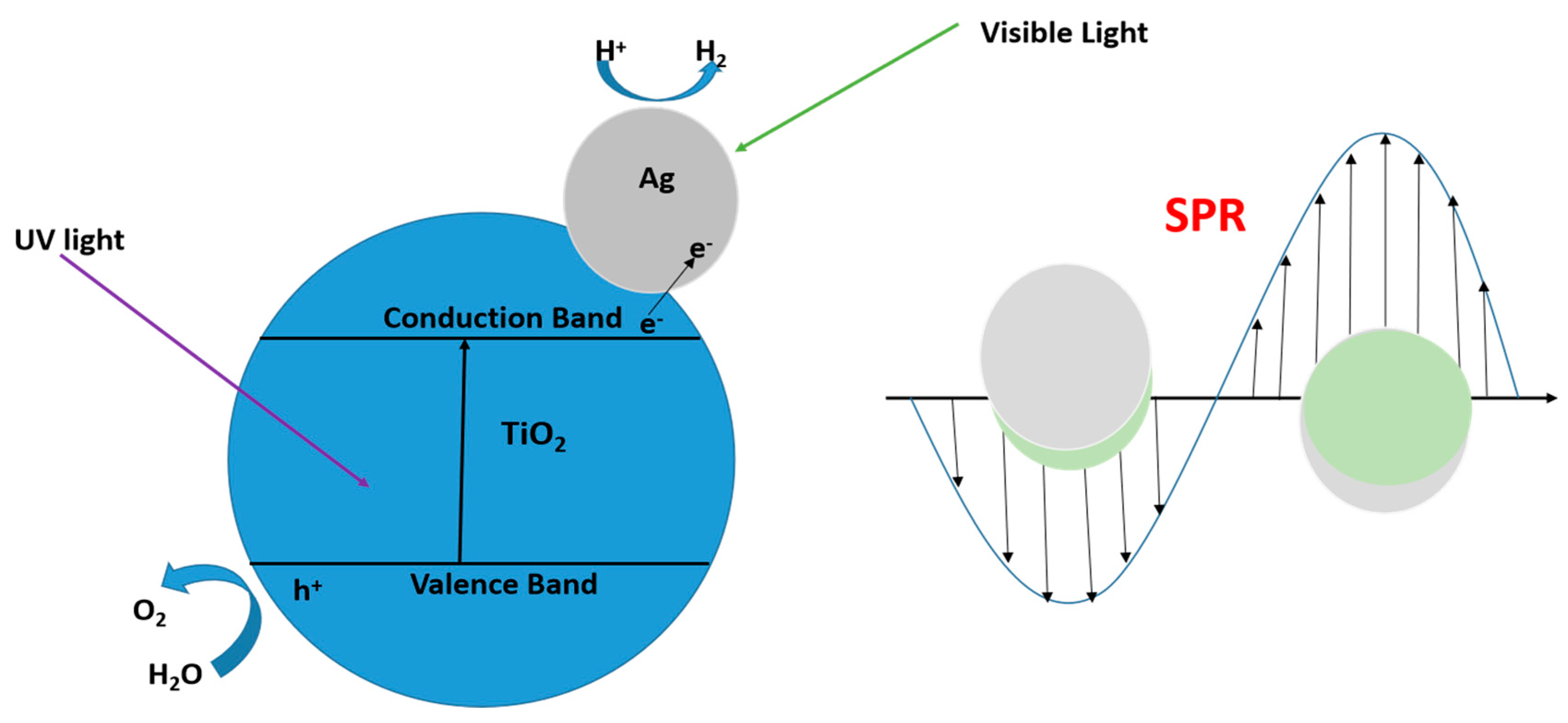
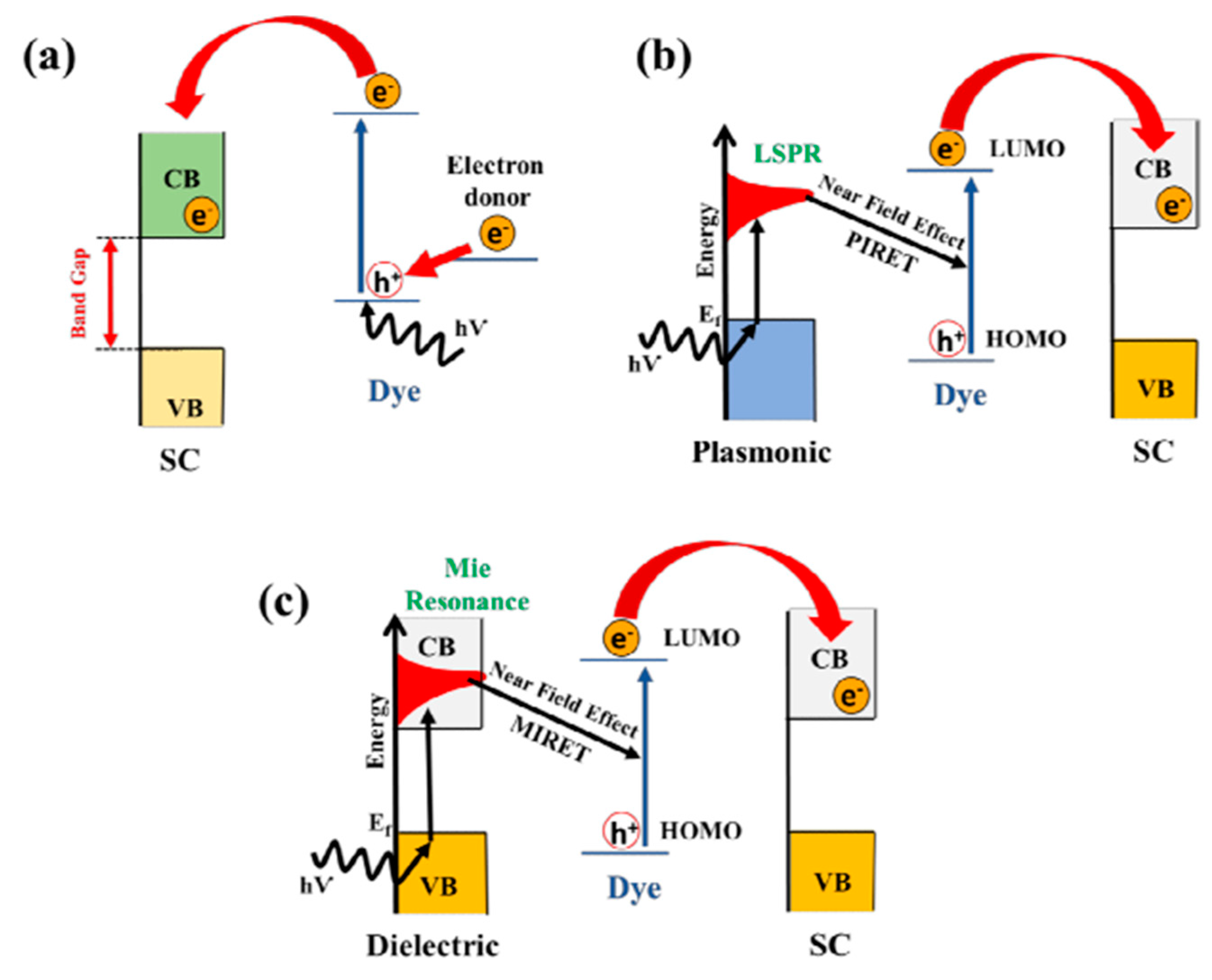
10.5. Surface Plasmon Resonance (SPR) Effect
10.6. Co-Catalyst

11. Observation of Charge Carrier Kinetics in Heterojunction Structure
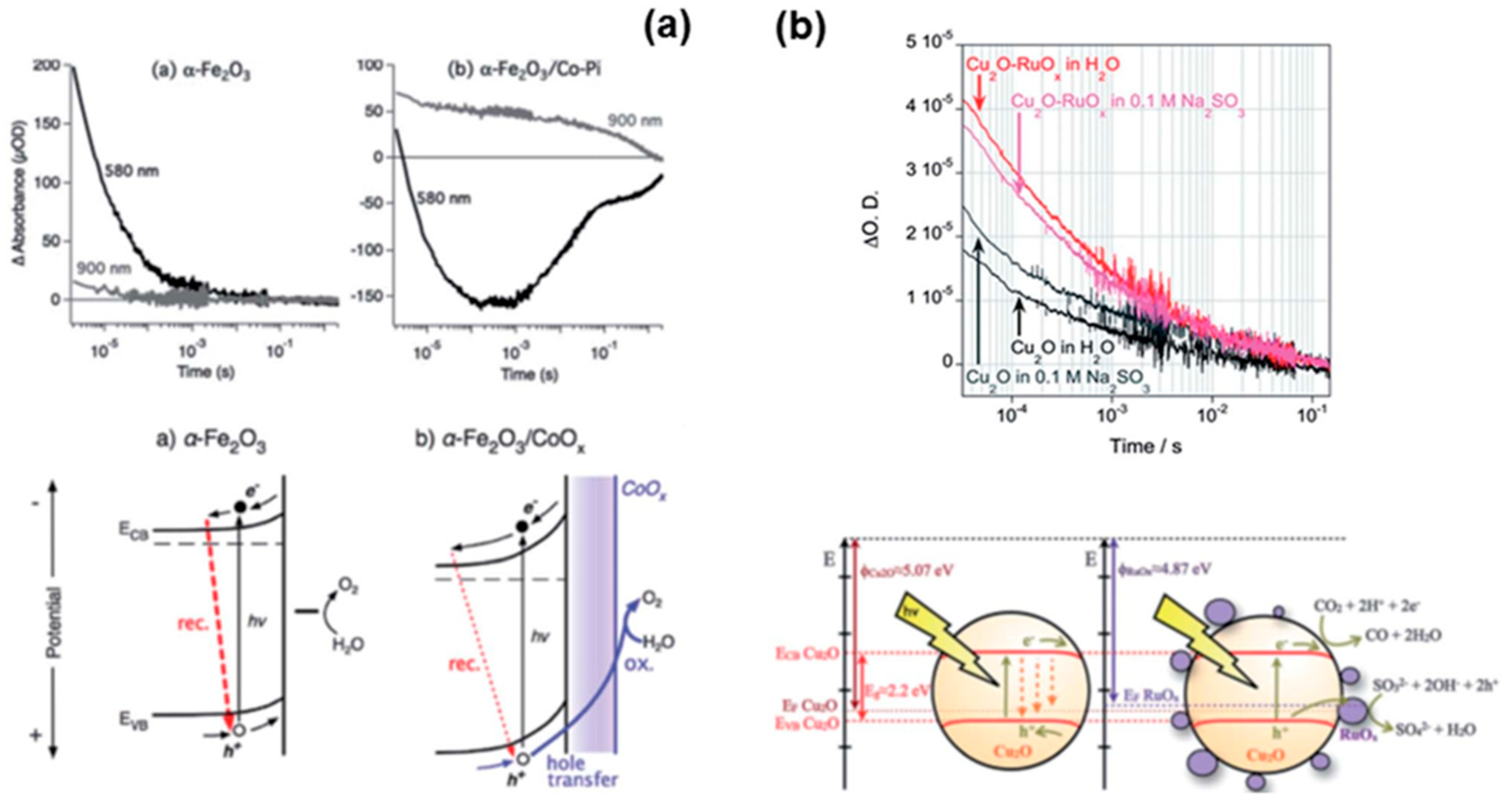
11.1. Transient Absorption Spectroscopy (TAS)
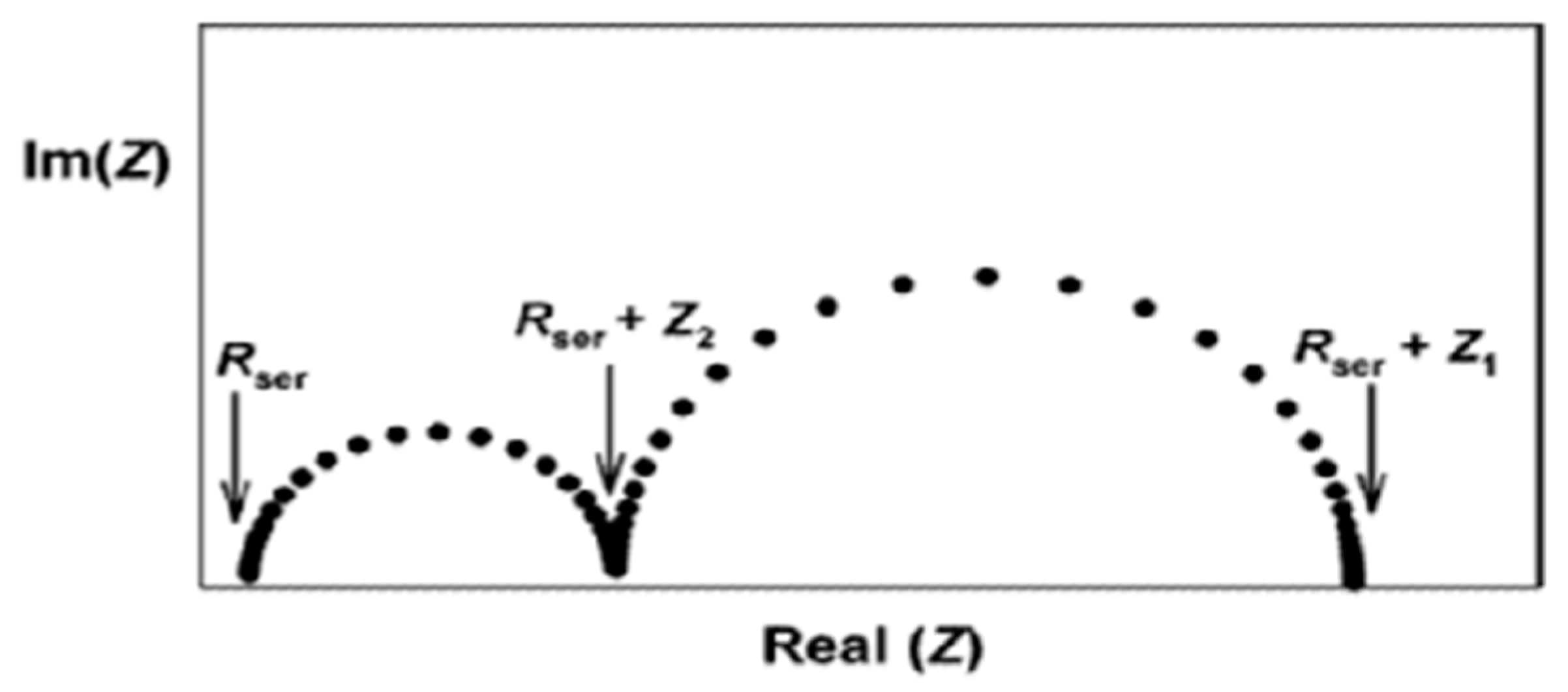
11.2. Electrochemical Impedance Spectroscopy (EIS)
11.3. Surface Photovoltage Spectroscopy
12. Theoretical Modelling of Photocatalyst Junction Structures
13. Conclusions and Future Perspectives
- Novel schemes should be developed that could maximize the light-harvesting capability of the TiO2 which in turn could offer a higher water-splitting rate to yield hydrogen.
- Designing dual-catalytic TiO2-based setups by mimicking the natural photocatalytic system is the best way to achieve sustainable energy. In this approach, another semiconductor is coupled with TiO2 that modifies its electronic states and offers a suitable path for the enhanced kinetics of water splitting to generate hydrogen.
- The addition of a dopant tunes the bandgap of TiO2, thus broadening its solar energy harvesting in the visible region, which is the first priority of the researchers for achieving a maximum energy input and minimal catalyst dose for the water-splitting reaction.
- Furthermore, a thorough understanding of the underlying reaction mechanism is a prerequisite to upsurge the catalytic proficiency of TiO2 by improving its charge segregation, charge utilization, and reduced charge recombination rate.
Author Contributions
Funding
Data Availability Statement
Acknowledgments
Conflicts of Interest
References
- Ahmad, A.; Tezcan, F.; Yerlikaya, G.; Paksoy, H.; Kardaş, G. Three dimensional rosette-rod TiO2/Bi2S3 heterojunction for enhanced photoelectrochemical water splitting. J. Alloys Compd. 2021, 868, 159133. [Google Scholar] [CrossRef]
- Osterloh, F.E.; Parkinson, B.A. Recent developments in solar water-splitting photocatalysis. MRS Bull. 2011, 36, 17–22. [Google Scholar] [CrossRef]
- Dawood, F.; Anda, M.; Shafiullah, G. Hydrogen production for energy: An overview. Int. J. Hydrogen Energy 2020, 45, 3847–3869. [Google Scholar] [CrossRef]
- Ishaq, T.; Yousaf, M.; Bhatti, I.A.; Batool, A.; Asghar, M.A.; Mohsin, M.; Ahmad, M. A perspective on possible amendments in semiconductors for enhanced photocatalytic hydrogen generation by water splitting. Int. J. Hydrogen Energy 2021, 46, 39036–39057. [Google Scholar] [CrossRef]
- Muscetta, M.; Andreozzi, R.; Clarizia, L.; Di Somma, I.; Marotta, R. Hydrogen production through photoreforming processes over Cu2O/TiO2 composite materials: A mini-review. Int. J. Hydrogen Energy 2020, 45, 28531–28552. [Google Scholar] [CrossRef]
- Hou, K.; Hughes, R. The kinetics of methane steam reforming over a Ni/α-Al2O catalyst. Chem. Eng. J. 2001, 82, 311–328. [Google Scholar] [CrossRef]
- Nowotny, J.; Sorrell, C.; Sheppard, L.; Bak, T. Solar-hydrogen: Environmentally safe fuel for the future. Int. J. Hydrogen Energy 2005, 30, 521–544. [Google Scholar] [CrossRef]
- Salam, M.A.; Ahmed, K.; Akter, N.; Hossain, T.; Abdullah, B. A review of hydrogen production via biomass gasification and its prospect in Bangladesh. Int. J. Hydrogen Energy 2018, 43, 14944–14973. [Google Scholar] [CrossRef]
- Shah, S.A.A. Feasibility study of renewable energy sources for developing the hydrogen economy in Pakistan. Int. J. Hydrogen Energy 2020, 45, 15841–15854. [Google Scholar] [CrossRef]
- Das, D.; Veziroglu, T.N. Advances in biological hydrogen production processes. Int. J. Hydrogen Energy 2008, 33, 6046–6057. [Google Scholar] [CrossRef]
- He, Y.-L.; Qiu, Y.; Wang, K.; Yuan, F.; Wang, W.-Q.; Li, M.-J.; Guo, J.-Q. Perspective of concentrating solar power. Energy 2020, 198, 117373. [Google Scholar] [CrossRef]
- Mallikarjuna, K.; Bari, G.A.R.; Vattikuti, S.P.; Kim, H. Synthesis of carbon-doped SnO2 nanostructures for visible-light-driven photocatalytic hydrogen production from water splitting. Int. J. Hydrogen Energy 2020, 45, 32789–32796. [Google Scholar] [CrossRef]
- Hassan, Q. Optimisation of solar-hydrogen power system for household applications. Int. J. Hydrogen Energy 2020, 45, 33111–33127. [Google Scholar] [CrossRef]
- Tahir, M.; Asiri, A.M.; Nawaz, T. A perspective on the fabrication of heterogeneous photocatalysts for enhanced hydrogen production. Int. J. Hydrogen Energy 2020, 45, 24544–24557. [Google Scholar] [CrossRef]
- Rusinque, B. Hydrogen Production by Photocatalytic Water Splitting under Near-UV and Visible Light Using Doped Pt and Pd TiO2. Master’s Thesis, The University of Western Ontario, London, ON, Canada, 2018. [Google Scholar]
- Rafique, M.; Mubashar, R.; Irshad, M.; Gillani, S.; Tahir, M.B.; Khalid, N.; Yasmin, A.; Shehzad, M.A. A comprehensive study on methods and materials for photocatalytic water splitting and hydrogen production as a renewable energy resource. J. Inorg. Organomet. Polym. Mater. 2020, 30, 3837–3861. [Google Scholar] [CrossRef]
- Cao, S.; Piao, L. Considerations for a more accurate evaluation method for photocatalytic water splitting. Angew. Chem. Int. Ed. 2020, 59, 18312–18320. [Google Scholar] [CrossRef]
- Saber, A.F.; Elewa, A.M.; Chou, H.-H.; EL-Mahdy, A.F. Donor-acceptor carbazole-based conjugated microporous polymers as photocatalysts for visible-light-driven H2 and O2 evolution from water splitting. Appl. Catal. B 2022, 316, 121624. [Google Scholar] [CrossRef]
- Guo, L.-J.; Luo, J.-W.; He, T.; Wei, S.-H.; Li, S.-S. Photocorrosion-limited maximum efficiency of solar photoelectrochemical water splitting. Phys. Rev. Appl. 2018, 10, 064059. [Google Scholar] [CrossRef]
- Guo, L.; Chen, Y.; Su, J.; Liu, M.; Liu, Y. Obstacles of solar-powered photocatalytic water splitting for hydrogen production: A perspective from energy flow and mass flow. Energy 2019, 172, 1079–1086. [Google Scholar] [CrossRef]
- Ning, X.; Lu, G. Photocorrosion inhibition of CdS-based catalysts for photocatalytic overall water splitting. Nanoscale 2020, 12, 1213–1223. [Google Scholar] [CrossRef]
- Singla, S.; Sharma, S.; Basu, S.; Shetti, N.P.; Aminabhavi, T.M. Photocatalytic water splitting hydrogen production via environmental benign carbon based nanomaterials. Int. J. Hydrogen Energy 2021, 46, 33696–33717. [Google Scholar] [CrossRef]
- Ni, M.; Leung, M.K.; Leung, D.Y.; Sumathy, K. A review and recent developments in photocatalytic water-splitting using TiO2 for hydrogen production. Renew. Sustain. Energy Rev. 2007, 11, 401–425. [Google Scholar] [CrossRef]
- Chowdhury, F.A.; Trudeau, M.L.; Guo, H.; Mi, Z. A photochemical diode artificial photosynthesis system for unassisted high efficiency overall pure water splitting. Nat. Commun. 2018, 9, 1707. [Google Scholar] [CrossRef] [PubMed]
- Moridon, S.N.F.; Salehmin, M.I.; Mohamed, M.A.; Arifin, K.; Minggu, L.J.; Kassim, M.B. Cobalt oxide as photocatalyst for water splitting: Temperature-dependent phase structures. Int. J. Hydrogen Energy 2019, 44, 25495–25504. [Google Scholar] [CrossRef]
- Li, S.; Xu, W.; Meng, L.; Tian, W.; Li, L. Recent progress on semiconductor heterojunction-based photoanodes for photoelectrochemical water splitting. Small Sci. 2022, 2, 2100112. [Google Scholar] [CrossRef]
- Badea, G.E.; Hora, C.; Maior, I.; Cojocaru, A.; Secui, C.; Filip, S.M.; Dan, F.C. Sustainable hydrogen production from seawater electrolysis: Through fundamental electrochemical principles to the most recent development. Energies 2022, 15, 8560. [Google Scholar] [CrossRef]
- Ishaq, T.; Yousaf, M.; Bhatti, I.A.; Ahmad, M.; Ikram, M.; Khan, M.U.; Qayyum, A. Photo-assisted splitting of water into hydrogen using visible-light activated silver doped g-C3N4 & CNTs hybrids. Int. J. Hydrogen Energy 2020, 45, 31574–31584. [Google Scholar]
- Bahramian, A.; Rezaeivala, M.; He, K.; Dionysiou, D.D. Enhanced visible-light photoelectrochemical hydrogen evolution through degradation of methyl orange in a cell based on coral-like Pt-deposited TiO2 thin film with sub-2 nm pores. Catal. Today 2019, 335, 333–344. [Google Scholar] [CrossRef]
- Iqbal, M.Z.; Siddique, S. Recent progress in efficiency of hydrogen evolution process based photoelectrochemical cell. Int. J. Hydrogen Energy 2018, 43, 21502–21523. [Google Scholar] [CrossRef]
- Qiu, Y.; Pan, Z.; Chen, H.; Ye, D.; Guo, L.; Fan, Z.; Yang, S. Current progress in developing metal oxide nanoarrays-based photoanodes for photoelectrochemical water splitting. Sci. Bull. 2019, 64, 1348–1380. [Google Scholar] [CrossRef]
- Murphy, A.B.; Barnes, P.R.; Randeniya, L.K.; Plumb, I.C.; Grey, I.E.; Horne, M.D.; Glasscock, J.A. Efficiency of solar water splitting using semiconductor electrodes. Int. J. Hydrogen Energy 2006, 31, 1999–2017. [Google Scholar] [CrossRef]
- Xu, Y.; Schoonen, M.A. The absolute energy positions of conduction and valence bands of selected semiconducting minerals. Am. Mineral. 2000, 85, 543–556. [Google Scholar] [CrossRef]
- Jiang, C.; Moniz, S.J.; Wang, A.; Zhang, T.; Tang, J. Photoelectrochemical devices for solar water splitting–materials and challenges. Chem. Soc. Rev. 2017, 46, 4645–4660. [Google Scholar] [CrossRef] [PubMed]
- Hu, C.-C.; Nian, J.-N.; Teng, H. Electrodeposited p-type Cu2O as photocatalyst for H2 evolution from water reduction in the presence of WO3. Sol. Energy Mater. Sol. Cells 2008, 92, 1071–1076. [Google Scholar] [CrossRef]
- McShane, C.M.; Choi, K.-S. Junction studies on electrochemically fabricated p–n Cu2O homojunction solar cells for efficiency enhancement. Phys. Chem. Chem. Phys. 2012, 14, 6112–6118. [Google Scholar] [CrossRef]
- Paracchino, A.; Laporte, V.; Sivula, K.; Grätzel, M.; Thimsen, E. Highly active oxide photocathode for photoelectrochemical water reduction. Nat. Mater. 2011, 10, 456–461. [Google Scholar] [CrossRef]
- Dominey, R.N.; Lewis, N.S.; Bruce, J.A.; Bookbinder, D.C.; Wrighton, M.S. Improvement of photoelectrochemical hydrogen generation by surface modification of p-type silicon semiconductor photocathodes. J. Am. Chem. Soc. 1982, 104, 467–482. [Google Scholar] [CrossRef]
- Hisatomi, T.; Kubota, J.; Domen, K. Recent advances in semiconductors for photocatalytic and photoelectrochemical water splitting. Chem. Soc. Rev. 2014, 43, 7520–7535. [Google Scholar] [CrossRef]
- Zheng, Q.; Zhou, B.; Bai, J.; Li, L.; Jin, Z.; Zhang, J.; Li, J.; Liu, Y.; Cai, W.; Zhu, X. Self-organized TiO2 nanotube array sensor for the determination of chemical oxygen demand. Adv. Mater.—Deerfield Beach Then Weinh. 2008, 20, 1044. [Google Scholar] [CrossRef]
- Qin, G.; Watanabe, A. Surface texturing of TiO2 film by mist deposition of TiO2 nanoparticles. Nano-Micro Lett. 2013, 5, 129–134. [Google Scholar] [CrossRef]
- Su, Z.; Zhou, W.; Jiang, F.; Hong, M. Anodic formation of nanoporous and nanotubular metal oxides. J. Mater. Chem. 2012, 22, 535–544. [Google Scholar] [CrossRef]
- Varghese, O.K.; Paulose, M.; Grimes, C.A. Long vertically aligned titania nanotubes on transparent conducting oxide for highly efficient solar cells. Nat. Nanotechnol. 2009, 4, 592–597. [Google Scholar] [CrossRef] [PubMed]
- Feng, X.; Shankar, K.; Varghese, O.K.; Paulose, M.; Latempa, T.J.; Grimes, C.A. Vertically aligned single crystal TiO2 nanowire arrays grown directly on transparent conducting oxide coated glass: Synthesis details and applications. Nano Lett. 2008, 8, 3781–3786. [Google Scholar] [CrossRef] [PubMed]
- Trang, T.; Tu, L.; Man, T.; Mathesh, M.; Nam, N.; Thu, V. A high-efficiency photoelectrochemistry of Cu2O/TiO2 nanotubes based composite for hydrogen evolution under sunlight. Compos. Part B 2019, 174, 106969. [Google Scholar] [CrossRef]
- Kumar, S.G.; Devi, L.G. Review on modified TiO2 photocatalysis under UV/visible light: Selected results and related mechanisms on interfacial charge carrier transfer dynamics. J. Phys. Chem. A 2011, 115, 13211–13241. [Google Scholar] [CrossRef]
- Liang, R.; Hu, A.; Persic, J.; Zhou, Y.N. Palladium nanoparticles loaded on carbon modified TiO2 nanobelts for enhanced methanol electrooxidation. Nano-Micro Lett. 2013, 5, 202–212. [Google Scholar] [CrossRef]
- Park, J.H.; Kim, S.; Bard, A.J. Novel carbon-doped TiO2 nanotube arrays with high aspect ratios for efficient solar water splitting. Nano Lett. 2006, 6, 24–28. [Google Scholar] [CrossRef]
- Siripala, W.; Ivanovskaya, A.; Jaramillo, T.F.; Baeck, S.-H.; McFarland, E.W. A Cu2O/TiO2 heterojunction thin film cathode for photoelectrocatalysis. Sol. Energy Mater. Sol. Cells 2003, 77, 229–237. [Google Scholar] [CrossRef]
- Xu, Q.C.; Wellia, D.V.; Ng, Y.H.; Amal, R.; Tan, T.T.Y. Synthesis of porous and visible-light absorbing Bi2WO6/TiO2 heterojunction films with improved photoelectrochemical and photocatalytic performances. J. Phys. Chem. C 2011, 115, 7419–7428. [Google Scholar] [CrossRef]
- Zhang, C.; Greenblatt, J.B.; Wei, M.; Eichman, J.; Saxena, S.; Muratori, M.; Guerra, O.J. Flexible grid-based electrolysis hydrogen production for fuel cell vehicles reduces costs and greenhouse gas emissions. Appl. Energy 2020, 278, 115651. [Google Scholar] [CrossRef]
- Guo, Y.; Li, G.; Zhou, J.; Liu, Y. Comparison between hydrogen production by alkaline water electrolysis and hydrogen production by PEM electrolysis. IOP Conf. Ser. Earth Environ. Sci. 2019, 371, 042022. [Google Scholar] [CrossRef]
- Dincer, I.; Acar, C. Review and evaluation of hydrogen production methods for better sustainability. Int. J. Hydrogen Energy 2015, 40, 11094–11111. [Google Scholar] [CrossRef]
- Nikolaidis, P.; Poullikkas, A. A comparative overview of hydrogen production processes. Renew. Sustain. Energy Rev. 2017, 67, 597–611. [Google Scholar] [CrossRef]
- Sun, H.; Tian, C.; Fan, G.; Qi, J.; Liu, Z.; Yan, Z.; Cheng, F.; Chen, J.; Li, C.P.; Du, M. Boosting activity on Co4N porous nanosheet by coupling CeO2 for efficient electrochemical overall water splitting at high current densities. Adv. Funct. Mater. 2020, 30, 1910596. [Google Scholar] [CrossRef]
- Wang, Y.; Pang, Y.; Xu, H.; Martinez, A.; Chen, K.S. PEM Fuel cell and electrolysis cell technologies and hydrogen infrastructure development–a review. Energy Environ. Sci. 2022, 15, 2288–2328. [Google Scholar] [CrossRef]
- Campbell-Stanway, C.; Becerra, V.; Prabhu, S.; Bull, J. Investigating the role of byproduct oxygen in uk-based future scenario models for green hydrogen electrolysis. Energies 2024, 17, 281. [Google Scholar] [CrossRef]
- Hu, C.; Zhang, L.; Gong, J. Recent progress made in the mechanism comprehension and design of electrocatalysts for alkaline water splitting. Energy Environ. Sci. 2019, 12, 2620–2645. [Google Scholar] [CrossRef]
- Ardo, S.; Rivas, D.F.; Modestino, M.A.; Greiving, V.S.; Abdi, F.F.; Llado, E.A.; Artero, V.; Ayers, K.; Battaglia, C.; Becker, J.-P. Pathways to electrochemical solar-hydrogen technologies. Energy Environ. Sci. 2018, 11, 2768–2783. [Google Scholar] [CrossRef]
- Berger, A.; Segalman, R.; Newman, J. Material requirements for membrane separators in a water-splitting photoelectrochemical cell. Energy Environ. Sci. 2014, 7, 1468–1476. [Google Scholar] [CrossRef]
- Cheng, W.-H.; De La Calle, A.; Atwater, H.A.; Stechel, E.B.; Xiang, C. Hydrogen from sunlight and water: A side-by-side comparison between photoelectrochemical and solar thermochemical water-splitting. ACS Energy Lett. 2021, 6, 3096–3113. [Google Scholar] [CrossRef]
- Oener, S.Z.; Twight, L.P.; Lindquist, G.A.; Boettcher, S.W. Thin cation-exchange layers enable high-current-density bipolar membrane electrolyzers via improved water transport. ACS Energy Lett. 2020, 6, 1–8. [Google Scholar] [CrossRef]
- Luo, T.; Abdu, S.; Wessling, M. Selectivity of ion exchange membranes: A review. J. Membr. Sci. 2018, 555, 429–454. [Google Scholar] [CrossRef]
- Giesbrecht, P.K.; Freund, M.S. Recent advances in bipolar membrane design and applications. Chem. Mater. 2020, 32, 8060–8090. [Google Scholar] [CrossRef]
- Yan, Z.; Mallouk, T.E. Bipolar membranes for ion management in (photo) electrochemical energy conversion. Acc. Mater. Res. 2021, 2, 1156–1166. [Google Scholar] [CrossRef]
- Kim, J.S.; Kim, B.; Kim, H.; Kang, K. Recent progress on multimetal oxide catalysts for the oxygen evolution reaction. Adv. Energy Mater. 2018, 8, 1702774. [Google Scholar] [CrossRef]
- Zhao, H.; Lu, D.; Wang, J.; Tu, W.; Wu, D.; Koh, S.W.; Gao, P.; Xu, Z.J.; Deng, S.; Zhou, Y. Raw biomass electroreforming coupled to green hydrogen generation. Nat. Commun. 2021, 12, 2008. [Google Scholar] [CrossRef] [PubMed]
- Li, C.; Bao, Y.; Liu, E.; Zhao, B.; Sun, T. Recent advances of modified Ni (Co, Fe)-based LDH 2D materials for water splitting. Molecules 2023, 28, 1475. [Google Scholar] [CrossRef]
- Pandev, M.; Terziev, V.; Abrashev, B. The evolution of hydrogen technologies: Paving the way to a sustainable hydrogen economy. Bulg. Chem. Commun. 2023, 55, 434–440. [Google Scholar]
- Hua, D.; Huang, J.; Fabbri, E.; Rafique, M.; Song, B. Development of anion exchange membrane water electrolysis and the associated challenges: A review. ChemElectroChem 2023, 10, e202200999. [Google Scholar] [CrossRef]
- Trattner, A.; Höglinger, M.; Macherhammer, M.G.; Sartory, M. Renewable hydrogen: Modular concepts from production over storage to the consumer. Chem. Ing. Tech. 2021, 93, 706–716. [Google Scholar] [CrossRef]
- López-Fernández, E.; Sacedón, C.G.; Gil-Rostra, J.; Yubero, F.; González-Elipe, A.R.; de Lucas-Consuegra, A. Recent advances in alkaline exchange membrane water electrolysis and electrode manufacturing. Molecules 2021, 26, 6326. [Google Scholar] [CrossRef] [PubMed]
- Colli, A.N.; Girault, H.H.; Battistel, A. Non-precious electrodes for practical alkaline water electrolysis. Materials 2019, 12, 1336. [Google Scholar] [CrossRef] [PubMed]
- Ju, W.; Heinz, M.V.; Pusterla, L.; Hofer, M.; Fumey, B.; Castiglioni, R.; Pagani, M.; Battaglia, C.; Vogt, U.F. Lab-scale alkaline water electrolyzer for bridging material fundamentals with realistic operation. ACS Sustain. Chem. Eng. 2018, 6, 4829–4837. [Google Scholar] [CrossRef]
- Vincent, I.; Lee, E.-C.; Kim, H.-M. Comprehensive impedance investigation of low-cost anion exchange membrane electrolysis for large-scale hydrogen production. Sci. Rep. 2021, 11, 293. [Google Scholar] [CrossRef] [PubMed]
- Wu, Q.; Wang, Y.; Zhang, K.; Xie, Z.; Sun, K.; An, W.; Liang, X.; Zou, X. Advances and status of anode catalysts for proton exchange membrane water electrolysis technology. Mater. Chem. Front. 2023, 7, 1025–1045. [Google Scholar] [CrossRef]
- Ferriday, T.; Middleton, P.; Kolhe, M. Determining the change in performance from replacing a separator with an anion exchange membrane for alkaline water electrolysis. J. Phys. Conf. Ser. 2023, 2454, 012003. [Google Scholar] [CrossRef]
- Henkensmeier, D.; Najibah, M.; Harms, C.; Žitka, J.; Hnát, J.; Bouzek, K. Overview: State-of-the art commercial membranes for anion exchange membrane water electrolysis. J. Electrochem. Energy Convers. Storage 2021, 18, 024001. [Google Scholar] [CrossRef]
- IRENA. Making the Breakthrough: Green Hydrogen Policies and Technology Costs; International Renewable Energy Agency: Abu Dhabi, United Arab Emirates, 2021. [Google Scholar]
- IRENA. Scaling up Electrolysers to Meet the 1.5 C Climate Goal; International Renewable Energy Agency: Abu Dhabi, United Arab Emirates, 2020. [Google Scholar]
- Iwasa, N.; Teng, Z.; Ma, G.; Hisatomi, T.; Domen, K. Synthesis of Narrow Band Gap Gallium Zinc Nitride Oxide Solid Solutions for Photocatalytic Water Splitting under Visible Light. Chem. Mater. 2024, 36, 2917–2924. [Google Scholar] [CrossRef]
- Navarro Yerga, R.M.; Álvarez Galván, M.C.; Del Valle, F.; Villoria de la Mano, J.A.; Fierro, J.L. Water splitting on semiconductor catalysts under visible-light irradiation. ChemSusChem Chem. Sustain. Energy Mater. 2009, 2, 471–485. [Google Scholar] [CrossRef]
- Fajrina, N.; Tahir, M. A critical review in strategies to improve photocatalytic water splitting towards hydrogen production. Int. J. Hydrogen Energy 2019, 44, 540–577. [Google Scholar] [CrossRef]
- Lisovski, O.; Piskunov, S.; Zhukovskii, Y.F.; Ozolins, J. Ab initio modeling of sulphur doped TiO2 nanotubular photocatalyst for water-splitting hydrogen generation. IOP Conf. Ser. Mater. Sci. Eng. 2012, 38, 012057. [Google Scholar] [CrossRef]
- Idriss, H. The elusive photocatalytic water splitting reaction using sunlight on suspended nanoparticles: Is there a way forward? Catal. Sci. Technol. 2020, 10, 304–310. [Google Scholar] [CrossRef]
- Niu, X.; Bai, X.; Zhou, Z.; Wang, J. Rational design and characterization of direct Z-scheme photocatalyst for overall water splitting from excited state dynamics simulations. ACS Catal. 2020, 10, 1976–1983. [Google Scholar] [CrossRef]
- Gholipour, M.R.; Dinh, C.-T.; Béland, F.; Do, T.-O. Nanocomposite heterojunctions as sunlight-driven photocatalysts for hydrogen production from water splitting. Nanoscale 2015, 7, 8187–8208. [Google Scholar] [CrossRef] [PubMed]
- Bernareggi, M.; Dozzi, M.V.; Bettini, L.G.; Ferretti, A.M.; Chiarello, G.L.; Selli, E. Flame-made Cu/TiO2 and Cu-Pt/TiO2 photocatalysts for hydrogen production. Catalysts 2017, 7, 301. [Google Scholar] [CrossRef]
- Vijayaraghavan, T.; Reddy, N.L.; Shankar, M.; Vadivel, S.; Ashok, A. A co-catalyst free, eco-friendly, novel visible light absorbing iron based complex oxide nanocomposites for enhanced photocatalytic hydrogen evolution. Int. J. Hydrogen Energy 2018, 43, 14417–14426. [Google Scholar] [CrossRef]
- Fujishima, A.; Honda, K. Electrochemical photolysis of water at a semiconductor electrode. Nature 1972, 238, 37–38. [Google Scholar] [CrossRef]
- Wang, B.; Shen, S.; Mao, S.S. Black TiO2 for solar hydrogen conversion. J. Mater. 2017, 3, 96–111. [Google Scholar]
- Eidsvåg, H.; Bentouba, S.; Vajeeston, P.; Yohi, S.; Velauthapillai, D. TiO2 as a photocatalyst for water splitting—An experimental and theoretical review. Molecules 2021, 26, 1687. [Google Scholar] [CrossRef]
- Haggerty, J.E.; Schelhas, L.T.; Kitchaev, D.A.; Mangum, J.S.; Garten, L.M.; Sun, W.; Stone, K.H.; Perkins, J.D.; Toney, M.F.; Ceder, G. High-fraction brookite films from amorphous precursors. Sci. Rep. 2017, 7, 15232. [Google Scholar] [CrossRef]
- Kaur, K.; Singh, C.V. Amorphous TiO2 as a photocatalyst for hydrogen production: A DFT study of structural and electronic properties. Energy Procedia 2012, 29, 291–299. [Google Scholar] [CrossRef]
- Zhang, W.; Yin, J.-R.; Tang, X.-Q.; Zhang, P.; Ding, Y.-H. Density functional theory studies on the structural and physical properties of Cu-doped anatase TiO2 (101) surface. Phys. E Low-Dimens. Syst. Nanostruct. 2017, 85, 259–263. [Google Scholar] [CrossRef]
- Morgade, C.I.; Cabeza, G.F. First-principles study of codoping TiO2 systems capable of improving the specific surface area and the dissociation of H2O to generate H2 and O2. Comput. Mater. Sci. 2017, 127, 204–210. [Google Scholar] [CrossRef]
- Rafique, M.; Hajra, S.; Irshad, M.; Usman, M.; Imran, M.; Assiri, M.A.; Ashraf, W.M. Hydrogen production using TiO2-based photocatalysts: A comprehensive review. ACS Omega 2023, 8, 25640–25648. [Google Scholar] [CrossRef] [PubMed]
- Zhu, Z.; Kao, C.-T.; Tang, B.-H.; Chang, W.-C.; Wu, R.-J. Efficient hydrogen production by photocatalytic water-splitting using Pt-doped TiO2 hollow spheres under visible light. Ceram. Int. 2016, 42, 6749–6754. [Google Scholar] [CrossRef]
- Aldosari, O.F.; Hussain, I. Unlocking the potential of TiO2-based photocatalysts for green hydrogen energy through water-splitting: Recent advances, future perspectives and techno feasibility assessment. Int. J. Hydrogen Energy 2024, 59, 958–981. [Google Scholar] [CrossRef]
- Jing, D.; Guo, L.; Zhao, L.; Zhang, X.; Liu, H.; Li, M.; Shen, S.; Liu, G.; Hu, X.; Zhang, X. Efficient solar hydrogen production by photocatalytic water splitting: From fundamental study to pilot demonstration. Int. J. Hydrogen Energy 2010, 35, 7087–7097. [Google Scholar] [CrossRef]
- Abe, R.; Sayama, K.; Arakawa, H. Significant effect of iodide addition on water splitting into H2 and O2 over Pt-loaded TiO2 photocatalyst: Suppression of backward reaction. Chem. Phys. Lett. 2003, 371, 360–364. [Google Scholar] [CrossRef]
- Liao, C.-H.; Huang, C.-W.; Wu, J.C. Hydrogen production from semiconductor-based photocatalysis via water splitting. Catalysts 2012, 2, 490–516. [Google Scholar] [CrossRef]
- Hogan, B. Ensuring a Future for Australian Coal Fired Power Station; Institute of Public Affairs: Melbourne, Australia, 2016. [Google Scholar]
- Sayama, K.; Arakawa, H. Photocatalytic decomposition of water and photocatalytic reduction of carbon dioxide over zirconia catalyst. J. Phys. Chem. 1993, 97, 531–533. [Google Scholar] [CrossRef]
- Zhang, A.; Liang, Y.; Zhang, H.; Geng, Z.; Zeng, J. Doping regulation in transition metal compounds for electrocatalysis. Chem. Soc. Rev. 2021, 50, 9817–9844. [Google Scholar] [CrossRef] [PubMed]
- Liu, Y.; Wang, W.; Xu, X.; Veder, J.-P.M.; Shao, Z. Recent advances in anion-doped metal oxides for catalytic applications. J. Mater. Chem. A 2019, 7, 7280–7300. [Google Scholar] [CrossRef]
- Samsudin, E.M.; Abd Hamid, S.B. Effect of band gap engineering in anionic-doped TiO2 photocatalyst. Appl. Surf. Sci. 2017, 391, 326–336. [Google Scholar] [CrossRef]
- Shon, H.; Phuntsho, S.; Okour, Y.; Cho, D.-L.; Kim, K.S.; Li, H.-J.; Na, S.; Kim, J.B.; Kim, J.-H. Visible light responsive titanium dioxide (TiO2). J. Korean Ind. Eng. Chem. 2008, 19, 1–16. [Google Scholar]
- Choi, S.K.; Yang, H.S.; Kim, J.H.; Park, H. Organic dye-sensitized TiO2 as a versatile photocatalyst for solar hydrogen and environmental remediation. Appl. Catal. B 2012, 121, 206–213. [Google Scholar] [CrossRef]
- Choi, W.; Termin, A.; Hoffmann, M.R. The role of metal ion dopants in quantum-sized TiO2: Correlation between photoreactivity and charge carrier recombination dynamics. J. Phys. Chem. 2002, 98, 13669–13679. [Google Scholar] [CrossRef]
- Zhao, W.; Wang, X.; Sang, H.; Wang, K. Synthesis of Bi-doped TiO2 nanotubes and enhanced photocatalytic activity for hydrogen evolution from glycerol solution. Chin. J. Chem. 2013, 31, 415–420. [Google Scholar] [CrossRef]
- Mohammadparast, F.; Tirumala, R.T.A.; Ramakrishnan, S.B.; Dadgar, A.P.; Andiappan, M. Operando UV–Vis spectroscopy as potential in-line PAT system for size determination of functioning metal nanocatalysts. Chem. Eng. Sci. 2020, 225, 115821. [Google Scholar] [CrossRef]
- Ahmad, H.; Kamarudin, S.; Minggu, L.J.; Kassim, M. Hydrogen from photo-catalytic water splitting process: A review. Renew. Sustain. Energy Rev. 2015, 43, 599–610. [Google Scholar] [CrossRef]
- Jaafarzadeh, N.; Ghanbari, F.; Ahmadi, M. Catalytic degradation of 2,4-dichlorophenoxyacetic acid (2,4-D) by nano-Fe2O3 activated peroxymonosulfate: Influential factors and mechanism determination. Chemosphere 2017, 169, 568–576. [Google Scholar] [CrossRef]
- Xu, C.; Zhang, Y.; Chen, J.; Lin, J.; Zhang, X.; Wang, Z.; Zhou, J. Enhanced mechanism of the photo-thermochemical cycle based on effective Fe-doping TiO2 films and DFT calculations. Appl. Catal. B 2017, 204, 324–334. [Google Scholar] [CrossRef]
- Sakar, M.; Mithun Prakash, R.; Do, T.-O. Insights into the TiO2-based photocatalytic systems and their mechanisms. Catalysts 2019, 9, 680. [Google Scholar] [CrossRef]
- Chibac-Scutaru, A.L.; Podasca, V.-E.; Melinte, V. Symbiotic coupling of ZnO nanoparticles and coumarin photosensitizer in soft polyurethane matrices for boosting visible-light photocatalytic performance. J. Environ. Chem. Eng. 2024, 12, 112312. [Google Scholar] [CrossRef]
- Lv, S.; Du, Y.; Wu, F.; Cai, Y.; Zhou, T. Review on LSPR assisted photocatalysis: Effects of physical fields and opportunities in multifield decoupling. Nanoscale Adv. 2022, 4, 2608–2631. [Google Scholar] [CrossRef] [PubMed]
- Zada, A.; Muhammad, P.; Ahmad, W.; Hussain, Z.; Ali, S.; Khan, M.; Khan, Q.; Maqbool, M. Surface plasmonic-assisted photocatalysis and optoelectronic devices with noble metal nanocrystals: Design, synthesis, and applications. Adv. Funct. Mater. 2020, 30, 1906744. [Google Scholar] [CrossRef]
- Sakar, M.; Annamalai, L. Plasmon-sensitized semiconductors for photocatalysis. In Handbook of Smart Photocatalytic Materials; Elsevier: Amsterdam, The Netherlands, 2020; pp. 175–205. [Google Scholar]
- Wu, F.; Hu, X.; Fan, J.; Liu, E.; Sun, T.; Kang, L.; Hou, W.; Zhu, C.; Liu, H. Photocatalytic activity of Ag/TiO2 nanotube arrays enhanced by surface plasmon resonance and application in hydrogen evolution by water splitting. Plasmonics 2013, 8, 501–508. [Google Scholar] [CrossRef]
- Guo, R.; Zeng, D.; Xie, Y.; Ling, Y.; Zhou, D.; Jiang, L.; Jiao, W.; Zhao, J.; Li, S. Carbon nitride quantum dots (CNQDs)/TiO2 nanoparticle heterojunction photocatalysts for enhanced ultraviolet-visible-light-driven bisphenol a degradation and H2 production. Int. J. Hydrogen Energy 2020, 45, 22534–22544. [Google Scholar] [CrossRef]
- Li, X.; Li, Y.; Wang, H.; Miao, H.; Zhu, H.; Liu, X.; Lin, H.; Shi, G. Fabrication of a three-dimensional bionic Si/TiO2/MoS2 photoelectrode for efficient solar water splitting. ACS Appl. Energy Mater. 2020, 4, 730–736. [Google Scholar] [CrossRef]
- Yuan, Y.; Guo, R.-t.; Hong, L.-f.; Ji, X.-y.; Lin, Z.-d.; Li, Z.-s.; Pan, W.-g. A review of metal oxide-based Z-scheme heterojunction photocatalysts: Actualities and developments. Mater. Today Energy 2021, 21, 100829. [Google Scholar] [CrossRef]
- Das, A.; Kumar, P.M.; Bhagavathiachari, M.; Nair, R.G. Hierarchical ZnO-TiO2 nanoheterojunction: A strategy driven approach to boost the photocatalytic performance through the synergy of improved surface area and interfacial charge transport. Appl. Surf. Sci. 2020, 534, 147321. [Google Scholar] [CrossRef]
- Zhang, L.; Jaroniec, M. Toward designing semiconductor-semiconductor heterojunctions for photocatalytic applications. Appl. Surf. Sci. 2018, 430, 2–17. [Google Scholar] [CrossRef]
- Zhang, Z.; Yates Jr, J.T. Band bending in semiconductors: Chemical and physical consequences at surfaces and interfaces. Chem. Rev. 2012, 112, 5520–5551. [Google Scholar] [CrossRef] [PubMed]
- Xu, M.; Ye, T.; Dai, F.; Yang, J.; Shen, J.; He, Q.; Chen, W.; Liang, N.; Zai, J.; Qian, X. Rationally designed n–n heterojunction with highly efficient solar hydrogen evolution. ChemSusChem 2015, 8, 1218–1225. [Google Scholar] [CrossRef]
- Wang, X.; Liu, G.; Chen, Z.-G.; Li, F.; Wang, L.; Lu, G.Q.; Cheng, H.-M. Enhanced photocatalytic hydrogen evolution by prolonging the lifetime of carriers in ZnO/CdS heterostructures. Chem. Commun. 2009, 3452–3454. [Google Scholar] [CrossRef] [PubMed]
- Low, J.; Jiang, C.; Cheng, B.; Wageh, S.; Al-Ghamdi, A.A.; Yu, J. A review of direct Z-scheme photocatalysts. Small Methods 2017, 1, 1700080. [Google Scholar] [CrossRef]
- Chen, L.; Zhou, X.; Jin, B.; Luo, J.; Xu, X.; Zhang, L.; Hong, Y. Heterojunctions in g-C3N4/B-TiO2 nanosheets with exposed {001} plane and enhanced visible-light photocatalytic activities. Int. J. Hydrogen Energy 2016, 41, 7292–7300. [Google Scholar] [CrossRef]
- He, H.; Lin, J.; Fu, W.; Wang, X.; Wang, H.; Zeng, Q.; Gu, Q.; Li, Y.; Yan, C.; Tay, B.K. MoS2/TiO2 edge-on heterostructure for efficient photocatalytic hydrogen evolution. Adv. Energy Mater. 2016, 6, 1600464. [Google Scholar] [CrossRef]
- Sun, B.; Zhou, W.; Li, H.; Ren, L.; Qiao, P.; Li, W.; Fu, H. Synthesis of particulate hierarchical tandem heterojunctions toward optimized photocatalytic hydrogen production. Adv. Mater. 2018, 30, 1804282. [Google Scholar] [CrossRef]
- Wang, Q.; Xiao, L.; Liu, X.; Sun, X.; Wang, J.; Du, H. Special Z-scheme Cu3P/TiO2 hetero-junction for efficient photocatalytic hydrogen evolution from water. J. Alloys Compd. 2022, 894, 162331. [Google Scholar] [CrossRef]
- Zheng, Z.; Zu, X.; Zhang, Y.; Zhou, W. Rational design of type-II nano-heterojunctions for nanoscale optoelectronics. Mater. Today Phys. 2020, 15, 100262. [Google Scholar] [CrossRef]
- Li, R.; Li, T.; Zhou, Q. Impact of titanium dioxide (TiO2) modification on its application to pollution treatment-a review. Catalysts 2020, 10, 804. [Google Scholar] [CrossRef]
- He, X.; Wang, A.; Wu, P.; Tang, S.; Zhang, Y.; Li, L.; Ding, P. Photocatalytic degradation of microcystin-LR by modified TiO2 photocatalysis: A review. Sci. Total Environ. 2020, 743, 140694. [Google Scholar] [CrossRef] [PubMed]
- Belabed, C.; Tab, A.; Bellal, B.; Belhamdi, B.; Benrakaa, N.; Trari, M. High photocatalytic performance for hydrogen production under visible light on the hetero-junction Pani-ZnO nanoparticles. Int. J. Hydrogen Energy 2021, 46, 17106–17115. [Google Scholar] [CrossRef]
- Zhang, W.; He, H.; Li, H.; Duan, L.; Zu, L.; Zhai, Y.; Li, W.; Wang, L.; Fu, H.; Zhao, D. Visible-light responsive TiO2-based materials for efficient solar energy utilization. Adv. Energy Mater. 2021, 11, 2003303. [Google Scholar] [CrossRef]
- Lu, H.; Hao, Q.; Chen, T.; Zhang, L.; Chen, D.; Ma, C.; Yao, W.; Zhu, Y. A high-performance Bi2O3/Bi2SiO5 pn heterojunction photocatalyst induced by phase transition of Bi2O3. Appl. Catal. B 2018, 237, 59–67. [Google Scholar] [CrossRef]
- Sakthivel, T.; Venugopal, G.; Durairaj, A.; Vasanthkumar, S.; Huang, X. Utilization of the internal electric field in semiconductor photocatalysis: A short review. J. Ind. Eng. Chem. 2019, 72, 18–30. [Google Scholar] [CrossRef]
- Yao, S.; Xue, S.; Shen, X. Photocatalytic activity of cuboid WO3 rods loaded with AgCl nanoparticles under visible light irradiation. J. Nanosci. Nanotechnol. 2017, 17, 5423–5431. [Google Scholar] [CrossRef]
- Li, X.; Garlisi, C.; Guan, Q.; Anwer, S.; Al-Ali, K.; Palmisano, G.; Zheng, L. A review of material aspects in developing direct Z-scheme photocatalysts. Mater. Today 2021, 47, 75–107. [Google Scholar] [CrossRef]
- Yang, H. A short review on heterojunction photocatalysts: Carrier transfer behavior and photocatalytic mechanisms. Mater. Res. Bull. 2021, 142, 111406. [Google Scholar] [CrossRef]
- Bai, S.; Jiang, J.; Zhang, Q.; Xiong, Y. Steering charge kinetics in photocatalysis: Intersection of materials syntheses, characterization techniques and theoretical simulations. Chem. Soc. Rev. 2015, 44, 2893–2939. [Google Scholar] [CrossRef]
- Wang, H.; Zhang, L.; Chen, Z.; Hu, J.; Li, S.; Wang, Z.; Liu, J.; Wang, X. Semiconductor heterojunction photocatalysts: Design, construction, and photocatalytic performances. Chem. Soc. Rev. 2014, 43, 5234–5244. [Google Scholar] [CrossRef] [PubMed]
- Cao, J.; Li, X.; Lin, H.; Chen, S.; Fu, X. In situ preparation of novel p–n junction photocatalyst BiOI/(BiO)2CO3 with enhanced visible light photocatalytic activity. J. Hazard. Mater. 2012, 239, 316–324. [Google Scholar] [CrossRef] [PubMed]
- Chen, C.; Cai, W.; Long, M.; Zhou, B.; Wu, Y.; Wu, D.; Feng, Y. Synthesis of visible-light responsive graphene oxide/TiO2 composites with p/n heterojunction. ACS Nano 2010, 4, 6425–6432. [Google Scholar] [CrossRef] [PubMed]
- Zhang, Z.; Shao, C.; Li, X.; Wang, C.; Zhang, M.; Liu, Y. Electrospun nanofibers of p-type NiO/n-type ZnO heterojunctions with enhanced photocatalytic activity. ACS Appl. Mater. Interfaces 2010, 2, 2915–2923. [Google Scholar] [CrossRef] [PubMed]
- Hasija, V.; Raizada, P.; Hosseini-Bandegharaei, A.; Singh, P.; Nguyen, V.-H. Synthesis and photocatalytic activity of Ni–Fe layered double hydroxide modified sulphur doped graphitic carbon nitride (SGCN/Ni–Fe LDH) photocatalyst for 2, 4-dinitrophenol degradation. Top. Catal. 2020, 63, 1030–1045. [Google Scholar] [CrossRef]
- Marcolongo, D.M.; Nocito, F.; Ditaranto, N.; Aresta, M.; Dibenedetto, A. Synthesis and characterization of pn junction ternary mixed oxides for photocatalytic coprocessing of CO2 and H2O. Catalysts 2020, 10, 980. [Google Scholar] [CrossRef]
- Mohammed, A.M.; Mohtar, S.S.; Aziz, F.; Aziz, M.; Ul-Hamid, A.; Salleh, W.N.W.; Yusof, N.; Jaafar, J.; Ismail, A.F. Ultrafast degradation of Congo Red dye using a facile one-pot solvothermal synthesis of cuprous oxide/titanium dioxide and cuprous oxide/zinc oxide pn heterojunction photocatalyst. Mater. Sci. Semicond. Process. 2021, 122, 105481. [Google Scholar] [CrossRef]
- Liu, W.; Chen, S.F. Visible-light activity evaluation of pn junction photocatalyst NiO/TiO2 prepared by sol-gel method. Adv. Mater. Res. 2011, 152, 441–449. [Google Scholar]
- Kumar, R.; El-Shishtawy, R.M.; Barakat, M.A. Synthesis and characterization of Ag-Ag2O/TiO2@ polypyrrole heterojunction for enhanced photocatalytic degradation of methylene blue. Catalysts 2016, 6, 76. [Google Scholar] [CrossRef]
- Prabhu, Y.T.; Rao, V.N.; Shankar, M.V.; Sreedhar, B.; Pal, U. The facile hydrothermal synthesis of CuO@ ZnO heterojunction nanostructures for enhanced photocatalytic hydrogen evolution. New J. Chem. 2019, 43, 6794–6805. [Google Scholar] [CrossRef]
- Zhang, X.; Wang, Y.; Liu, B.; Sang, Y.; Liu, H. Heterostructures construction on TiO2 nanobelts: A powerful tool for building high-performance photocatalysts. Appl. Catal. B 2017, 202, 620–641. [Google Scholar] [CrossRef]
- Chu, L.; Li, M.; Cui, P.; Jiang, Y.; Wan, Z.; Dou, S. The study of NiO/TiO2 photocatalytic activity for degradation of methylene orange. Energy Environ. Focus 2014, 3, 371–374. [Google Scholar] [CrossRef]
- Lin, J.; Shen, J.; Wang, R.; Cui, J.; Zhou, W.; Hu, P.; Liu, D.; Liu, H.; Wang, J.; Boughton, R.I. Nano-p–n junctions on surface-coarsened TiO2 nanobelts with enhanced photocatalytic activity. J. Mater. Chem. 2011, 21, 5106–5113. [Google Scholar] [CrossRef]
- Zhao, L.; Cui, T.; Li, Y.; Wang, B.; Han, J.; Han, L.; Liu, Z. Efficient visible light photocatalytic activity of p–n junction CuO/TiO2 loaded on natural zeolite. RSC Adv. 2015, 5, 64495–64502. [Google Scholar] [CrossRef]
- Wang, M.; Hu, Y.; Han, J.; Guo, R.; Xiong, H.; Yin, Y. TiO2/NiO hybrid shells: P–n junction photocatalysts with enhanced activity under visible light. J. Mater. Chem. A 2015, 3, 20727–20735. [Google Scholar] [CrossRef]
- Nair, S.B.; Joseph, J.A.; Babu, S.; Shinoj, V.; Remillard, S.K.; Shaji, S.; Philip, R.R. Influence of pn junction mechanism and alumina overlayer on the photocatalytic performance of TiO2 nanotubes. Nanotechnology 2020, 31, 275403. [Google Scholar] [CrossRef]
- Wang, S.; Huang, C.-Y.; Pan, L.; Chen, Y.; Zhang, X.; Zou, J.-J. Controllable fabrication of homogeneous ZnO pn junction with enhanced charge separation for efficient photocatalysis. Catal. Today 2019, 335, 151–159. [Google Scholar] [CrossRef]
- Yu, J.; Wang, S.; Low, J.; Xiao, W. Enhanced photocatalytic performance of direct Z-scheme gC3N4–TiO2 photocatalysts for the decomposition of formaldehyde in air. Phys. Chem. Chem. Phys. 2013, 15, 16883–16890. [Google Scholar] [CrossRef]
- Liu, D.; Chen, S.; Li, R.; Peng, T. Review of Z-scheme heterojunctions for photocatalytic energy conversion. Acta Phys.-Chim. Sin 2021, 37, 2010017. [Google Scholar] [CrossRef]
- Li, H.; Tu, W.; Zhou, Y.; Zou, Z. Z-Scheme photocatalytic systems for promoting photocatalytic performance: Recent progress and future challenges. Adv. Sci. 2016, 3, 1500389. [Google Scholar] [CrossRef]
- Iwase, A.; Kudo, A. Development of Ir and La-codoped BaTa2O6 photocatalysts using visible light up to 640 nm as an H2-evolving photocatalyst for Z-schematic water splitting. Chem. Commun. 2017, 53, 6156–6159. [Google Scholar] [CrossRef] [PubMed]
- Miseki, Y.; Fujiyoshi, S.; Gunji, T.; Sayama, K. Photocatalytic Z-scheme water splitting for independent H2/O2 production via a stepwise operation employing a vanadate redox mediator under visible light. J. Phys. Chem. C 2017, 121, 9691–9697. [Google Scholar] [CrossRef]
- Abe, R.; Sayama, K.; Domen, K.; Arakawa, H. A new type of water splitting system composed of two different TiO2 photocatalysts (anatase, rutile) and a IO3−/I− shuttle redox mediator. Chem. Phys. Lett. 2001, 344, 339–344. [Google Scholar] [CrossRef]
- Ng, B.J.; Putri, L.K.; Kong, X.Y.; Teh, Y.W.; Pasbakhsh, P.; Chai, S.P. Z-scheme photocatalytic systems for solar water splitting. Adv. Sci. 2020, 7, 1903171. [Google Scholar] [CrossRef] [PubMed]
- Abe, R.; Shinmei, K.; Koumura, N.; Hara, K.; Ohtani, B. Visible-light-induced water splitting based on two-step photoexcitation between dye-sensitized layered niobate and tungsten oxide photocatalysts in the presence of a triiodide/iodide shuttle redox mediator. J. Am. Chem. Soc. 2013, 135, 16872–16884. [Google Scholar] [CrossRef]
- Wang, Y.; Suzuki, H.; Xie, J.; Tomita, O.; Martin, D.J.; Higashi, M.; Kong, D.; Abe, R.; Tang, J. Mimicking natural photosynthesis: Solar to renewable H2 fuel synthesis by Z-scheme water splitting systems. Chem. Rev. 2018, 118, 5201–5241. [Google Scholar] [CrossRef]
- Abe, R. Development of a new system for photocatalytic water splitting into H2 and O2 under visible light irradiation. Bull. Chem. Soc. Jpn. 2011, 84, 1000–1030. [Google Scholar] [CrossRef]
- Deshpande, A.; Shah, P.; Gholap, R.; Gupta, N.M. Interfacial and physico-chemical properties of polymer-supported CdS ZnS nanocomposites and their role in the visible-light mediated photocatalytic splitting of water. J. Colloid Interface Sci. 2009, 333, 263–268. [Google Scholar] [CrossRef]
- Maeda, K. Z-scheme water splitting using two different semiconductor photocatalysts. ACS Catal. 2013, 3, 1486–1503. [Google Scholar] [CrossRef]
- Wen Teh, Y.; Wei Goh, Y.; Ying Kong, X.; Ng, B.J.; Yong, S.T.; Chai, S.P. Fabrication of Bi2WO6/Cu/WO3 all-Solid-State Z-scheme composite photocatalyst to improve CO2 photoreduction under visible light irradiation. ChemCatChem 2019, 11, 6431–6438. [Google Scholar] [CrossRef]
- Maeda, K.; Domen, K. Photocatalytic water splitting: Recent progress and future challenges. J. Phys. Chem. Lett. 2010, 1, 2655–2661. [Google Scholar] [CrossRef]
- Lincho, J.; Mazierski, P.; Klimczuk, T.; Martins, R.C.; Gomes, J.; Zaleska-Medynska, A. TiO2 nanotubes modification by photodeposition with noble metals: Characterization, optimization, photocatalytic activity, and by-products analysis. J. Environ. Chem. Eng. 2024, 12, 112990. [Google Scholar] [CrossRef]
- Yao, G.-Y.; Liu, Q.-L.; Zhao, Z.-Y. Studied localized surface plasmon resonance effects of Au nanoparticles on TiO2 by FDTD simulations. Catalysts 2018, 8, 236. [Google Scholar] [CrossRef]
- Shehzad, N.; Tahir, M.; Johari, K.; Murugesan, T.; Hussain, M. A critical review on TiO2 based photocatalytic CO2 reduction system: Strategies to improve efficiency. J. CO2 Util. 2018, 26, 98–122. [Google Scholar] [CrossRef]
- Khatun, F.; Abd Aziz, A.; Sim, L.C.; Monir, M.U. Plasmonic enhanced Au decorated TiO2 nanotube arrays as a visible light active catalyst towards photocatalytic CO2 conversion to CH4. J. Environ. Chem. Eng. 2019, 7, 103233. [Google Scholar] [CrossRef]
- Xie, S.; Zhang, H.; Liu, G.; Wu, X.; Lin, J.; Zhang, Q.; Wang, Y. Tunable localized surface plasmon resonances in MoO3− x-TiO2 nanocomposites with enhanced catalytic activity for CO2 photoreduction under visible light. Chin. J. Catal. 2020, 41, 1125–1131. [Google Scholar] [CrossRef]
- Chen, Q.; Zhang, M.; Li, J.; Zhang, G.; Xin, Y.; Chai, C. Construction of immobilized 0D/1D heterostructure photocatalyst Au/CuS/CdS/TiO2 NBs with enhanced photocatalytic activity towards moxifloxacin degradation. Chem. Eng. J. 2020, 389, 124476. [Google Scholar] [CrossRef]
- Li, G.; Huang, J.; Chen, J.; Deng, Z.; Huang, Q.; Liu, Z.; Guo, W.; Cao, R. Highly active photocatalyst of Cu2O/TiO2 octahedron for hydrogen generation. ACS Omega 2019, 4, 3392–3397. [Google Scholar] [CrossRef]
- Liu, X.; Iocozzia, J.; Wang, Y.; Cui, X.; Chen, Y.; Zhao, S.; Li, Z.; Lin, Z. Noble metal–metal oxide nanohybrids with tailored nanostructures for efficient solar energy conversion, photocatalysis and environmental remediation. Energy Environ. Sci. 2017, 10, 402–434. [Google Scholar] [CrossRef]
- Miyoshi, A.; Nishioka, S.; Maeda, K. Water splitting on rutile TiO2-based photocatalysts. Chem.–A Eur. J. 2018, 24, 18204–18219. [Google Scholar] [CrossRef]
- Maeda, K. Direct splitting of pure water into hydrogen and oxygen using rutile titania powder as a photocatalyst. Chem. Commun. 2013, 49, 8404–8406. [Google Scholar] [CrossRef] [PubMed]
- Sayama, K.; Arakawa, H. Effect of carbonate salt addition on the photocatalytic decomposition of liquid water over Pt–TiO2 catalyst. J. Chem. Soc. Faraday Trans. 1997, 93, 1647–1654. [Google Scholar] [CrossRef]
- Moniz, S.J.; Shevlin, S.A.; Martin, D.J.; Guo, Z.-X.; Tang, J. Visible-light driven heterojunction photocatalysts for water splitting–a critical review. Energy Environ. Sci. 2015, 8, 731–759. [Google Scholar] [CrossRef]
- Han, S.; Yun, Q.; Tu, S.; Zhu, L.; Cao, W.; Lu, Q. Metallic ruthenium-based nanomaterials for electrocatalytic and photocatalytic hydrogen evolution. J. Mater. Chem. A 2019, 7, 24691–24714. [Google Scholar] [CrossRef]
- Yamada, Y.; Shikano, S.; Fukuzumi, S. Robustness of Ru/SiO2 as a hydrogen-evolution catalyst in a photocatalytic system using an organic photocatalyst. J. Phys. Chem. C 2013, 117, 13143–13152. [Google Scholar] [CrossRef]
- Gu, Q.; Gao, Z.; Yu, S.; Xue, C. Constructing Ru/TiO2 heteronanostructures toward enhanced photocatalytic water splitting via a RuO2/TiO2 heterojunction and Ru/TiO2 Schottky junction. Adv. Mater. Interfaces 2016, 3, 1500631. [Google Scholar] [CrossRef]
- Rozman, N.; Nadrah, P.; Cornut, R.; Jousselme, B.; Bele, M.; Dražić, G.; Gaberšček, M.; Kunej, Š.; Škapin, A.S. TiO2 photocatalyst with single and dual noble metal co-catalysts for efficient water splitting and organic compound removal. Int. J. Hydrogen Energy 2021, 46, 32871–32881. [Google Scholar] [CrossRef]
- Loncar, A.; Moriau, L.; Stojanovski, K.; Ruiz-Zepeda, F.; Jovanovic, P.; Bele, M.; Gaberscek, M.; Hodnik, N. Ir/TiONx/C high-performance oxygen evolution reaction nanocomposite electrocatalysts in acidic media: Synthesis, characterization and electrochemical benchmarking protocol. J. Phys. Energy 2020, 2, 02LT01. [Google Scholar] [CrossRef]
- Gómez-Cerezo, N.; Sayago-Carro, R.; Cortés-Bazo, A.; Fernández-García, M.; Kubacka, A. PdCu deposited alloys on TiO2 for hydrogen photo-production. Catal. Today 2023, 423, 114280. [Google Scholar] [CrossRef]
- Zhou, X.; Dong, H. A theoretical perspective on charge separation and transfer in metal oxide photocatalysts for water splitting. ChemCatChem 2019, 11, 3688–3715. [Google Scholar] [CrossRef]
- Rahman, Z.U.; Wei, N.; Feng, M.; Wang, D. TiO2 hollow spheres with separated Au and RuO2 co-catalysts for efficient photocatalytic water splitting. Int. J. Hydrogen Energy 2019, 44, 13221–13231. [Google Scholar] [CrossRef]
- Fuentes, R.E.; Farell, J.; Weidner, J.W. Multimetallic electrocatalysts of Pt, Ru, and Ir supported on anatase and rutile TiO2 for oxygen evolution in an acid environment. Electrochem. Solid-State Lett. 2010, 14, E5. [Google Scholar] [CrossRef]
- Tanaka, A.; Sakaguchi, S.; Hashimoto, K.; Kominami, H. Preparation of Au/TiO2 with metal cocatalysts exhibiting strong surface plasmon resonance effective for photoinduced hydrogen formation under irradiation of visible light. ACS Catal. 2013, 3, 79–85. [Google Scholar] [CrossRef]
- Rutkowska, I.A.; Kulesza, P.J. Electroanalysis of ethanol oxidation and reactivity of platinum-ruthenium catalysts supported onto nanostructured titanium dioxide matrices. J. Electrochem. Soc. 2015, 163, H3052. [Google Scholar] [CrossRef]
- Lima, M.J.; Tavares, P.B.; Silva, A.M.; Silva, C.G.; Faria, J.L. Selective photocatalytic oxidation of benzyl alcohol to benzaldehyde by using metal-loaded g-C3N4 photocatalysts. Catal. Today 2017, 287, 70–77. [Google Scholar] [CrossRef]
- Caudillo-Flores, U.; Barba-Nieto, I.; Gómez-Cerezo, M.N.; Martínez-Arias, A.; Fernández-García, M.; Kubacka, A. Toward the green production of H2: Binary Pt–Ru promoted Nb-TiO2 based photocatalysts. ACS Sustain. Chem. Eng. 2019, 7, 15671–15683. [Google Scholar] [CrossRef]
- Gyawali, S.; Tirumala, R.T.; Andiappan, M.; Bristow, A.D. Carrier dynamics in cuprous oxide-based nanoparticles and heterojunctions. In Proceedings of the Ultrafast Phenomena and Nanophotonics XXVIII, San Francisco, CA, USA, 27 January–1 February 2024; pp. 73–79. [Google Scholar]
- Berera, R.; van Grondelle, R.; Kennis, J.T. Ultrafast transient absorption spectroscopy: Principles and application to photosynthetic systems. Photosynth. Res. 2009, 101, 105–118. [Google Scholar] [CrossRef]
- Tang, J.; Cowan, A.J.; Durrant, J.R.; Klug, D.R. Mechanism of O2 production from water splitting: Nature of charge carriers in nitrogen doped nanocrystalline TiO2 films and factors limiting O2 production. J. Phys. Chem. C 2011, 115, 3143–3150. [Google Scholar] [CrossRef]
- Pendlebury, S.R.; Barroso, M.; Cowan, A.J.; Sivula, K.; Tang, J.; Grätzel, M.; Klug, D.; Durrant, J.R. Dynamics of photogenerated holes in nanocrystalline α-Fe2O3 electrodes for water oxidation probed by transient absorption spectroscopy. Chem. Commun. 2011, 47, 716–718. [Google Scholar] [CrossRef]
- Pendlebury, S.R.; Cowan, A.J.; Barroso, M.; Sivula, K.; Ye, J.; Grätzel, M.; Klug, D.R.; Tang, J.; Durrant, J.R. Correlating long-lived photogenerated hole populations with photocurrent densities in hematite water oxidation photoanodes. Energy Environ. Sci. 2012, 5, 6304–6312. [Google Scholar] [CrossRef]
- Barroso, M.; Mesa, C.A.; Pendlebury, S.R.; Cowan, A.J.; Hisatomi, T.; Sivula, K.; Grätzel, M.; Klug, D.R.; Durrant, J.R. Dynamics of photogenerated holes in surface modified α-Fe2O3 photoanodes for solar water splitting. Proc. Natl. Acad. Sci. USA 2012, 109, 15640–15645. [Google Scholar] [CrossRef] [PubMed]
- Pastor, E.; Pesci, F.M.; Reynal, A.; Handoko, A.D.; Guo, M.; An, X.; Cowan, A.J.; Klug, D.R.; Durrant, J.R.; Tang, J. Interfacial charge separation in Cu2O/RuOx as a visible light driven CO2 reduction catalyst. Phys. Chem. Chem. Phys. 2014, 16, 5922–5926. [Google Scholar] [CrossRef] [PubMed]
- Ma, Y.; Pendlebury, S.R.; Reynal, A.; Le Formal, F.; Durrant, J.R. Dynamics of photogenerated holes in undoped BiVO4 photoanodes for solar water oxidation. Chem. Sci. 2014, 5, 2964–2973. [Google Scholar] [CrossRef]
- Pesci, F.M.; Cowan, A.J.; Alexander, B.D.; Durrant, J.R.; Klug, D.R. Charge carrier dynamics on mesoporous WO3 during water splitting. J. Phys. Chem. Lett. 2011, 2, 1900–1903. [Google Scholar] [CrossRef]
- Gelderman, K.; Lee, L.; Donne, S. Flat-band potential of a semiconductor: Using the Mott–Schottky equation. J. Chem. Educ. 2007, 84, 685. [Google Scholar] [CrossRef]
- Tahir, A.A.; Burch, H.A.; Wijayantha, K.U.; Pollet, B.G. A new route to control texture of materials: Nanostructured ZnFe2O4 photoelectrodes. Int. J. Hydrogen Energy 2013, 38, 4315–4323. [Google Scholar] [CrossRef]
- Steiner, K.; Chen, W.; Pasquarello, A. Band offsets of lattice-matched semiconductor heterojunctions through hybrid functionals and G0W0. Phys. Rev. B 2014, 89, 205309. [Google Scholar] [CrossRef]
- Shevlin, S.; Guo, Z. Density functional theory simulations of complex hydride and carbon-based hydrogen storage materials. Chem. Soc. Rev. 2009, 38, 211–225. [Google Scholar] [CrossRef]
- Perdew, J.P.; Levy, M. Physical content of the exact Kohn-Sham orbital energies: Band gaps and derivative discontinuities. Phys. Rev. Lett. 1983, 51, 1884. [Google Scholar] [CrossRef]
- Anisimov, V.I.; Zaanen, J.; Andersen, O.K. Band theory and Mott insulators: Hubbard U instead of Stoner I. Phys. Rev. B 1991, 44, 943. [Google Scholar] [CrossRef]
- Zhang, X.; Peng, T.; Song, S. Recent advances in dye-sensitized semiconductor systems for photocatalytic hydrogen production. J. Mater. Chem. A 2016, 4, 2365–2402. [Google Scholar] [CrossRef]
- Yun, S.; Vlachopoulos, N.; Qurashi, A.; Ahmad, S.; Hagfeldt, A. Dye sensitized photoelectrolysis cells. Chem. Soc. Rev. 2019, 48, 3705–3722. [Google Scholar] [CrossRef] [PubMed]
- Vedhanarayanan, B.; Chen, C.-C.; Lin, T.-W. Plasmon-enhanced photocatalytic hydrogen production by dual dye sensitized ternary composite of MoS3/Au core-Ag shell nanoparticles/graphene. J. Power Sources 2020, 477, 229033. [Google Scholar] [CrossRef]
- Addanki Tirumala, R.T.; Khatri, N.; Ramakrishnan, S.B.; Mohammadparast, F.; Khan, M.T.; Tan, S.; Wagle, P.; Puri, S.; McIlroy, D.N.; Kalkan, A.K. Tuning Catalytic Activity and Selectivity in Photocatalysis on Mie-Resonant Cuprous Oxide Particles: Distinguishing Electromagnetic Field Enhancement Effect from the Heating Effect. ACS Sustain. Chem. Eng. 2023, 11, 15931–15940. [Google Scholar] [CrossRef]
- Li, J.; Cushing, S.K.; Meng, F.; Senty, T.R.; Bristow, A.D.; Wu, N. Plasmon-induced resonance energy transfer for solar energy conversion. Nat. Photonics 2015, 9, 601–607. [Google Scholar] [CrossRef]
- Cambiasso, J.; König, M.; Cortes, E.; Schlücker, S.; Maier, S.A. Surface-enhanced spectroscopies of a molecular monolayer in an all-dielectric nanoantenna. Acs Photonics 2018, 5, 1546–1557. [Google Scholar] [CrossRef]


| Method | Technique Used | Feed Stock | Title |
|---|---|---|---|
| Photonic | PV electrolysis | Water | Electricity is produced using PV panels |
| Photocatalysis | Water | Using electron–hole pairs produced by the photocatalyst, water is divided into O2 and H2 | |
| Photo-electrochemical method | Water | A hybrid cell generates voltage and current to absorb light | |
| Biochemical | Dark fermentation | Biomass | A hybrid cell generates voltage and current to absorb light |
| Electrical + Thermal | High temperature electrolysis | Water | Water splitting occurs at a high temperature using thermal and electrical energy |
| Hybrid thermochemical cycle | Water | Cycles of chemical reactions are driven by electrical and thermal energy | |
| Coal gasification | Coal | Coal is transformed into syn-gas | |
| Reforming of fossil fuel | Fossil fuel | Fossil fuels produce H2 and CO2 | |
| Electrical | Electrolysis | Water | Water is split by direct current into O2 and H2 |
| Plasma | Fossil fuels | Carbon soot and H2 are produced when natural gas is pushed through a plasma arc | |
| Thermal | Thermolysis | H2S | H2S thermally decomposes at high temperatures |
| Thermochemical processes | Water splitting | Water | Water is oxidized by converting sunlight into electron–hole pairs |
| Biomass conversion | Biomass | Conversion of fermentable hydrogen via thermo-catalysis using biomass-based materials | |
| Gasification | Biomass | Biomass is transformed into syn-gas | |
| Reforming | Biomass | liquid bio fuels to transform into H2 |
| Characteristic | PEM | AEM | Alkaline | SOEC |
|---|---|---|---|---|
| Electrolyte | Proton-exchange membrane | Anion-exchange membrane | Liquid KOH solution | Solid oxide ceramics (e.g., YSZ) |
| Electrolyte Material | Acidic/solid (polymer) | Alkaline/solid (polymer) | Alkaline/liquid | O2 or H+ conducting/solid (ceramic) |
| Working Principle | 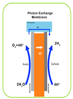 | 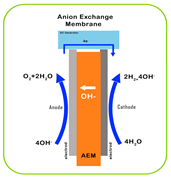 | 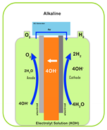 | 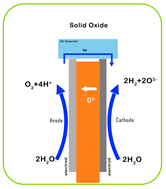 |
| Operating Temperature | 50–80 °C | 40–90 °C | 60–80 °C | 700–1000 °C |
| Electrode Material | Platinum group metals (PGMs) | Non-precious metals | Nickel-based | Perovskites, ceramics |
| Efficiency | 60–70% | 50–60% | 65–70% | 80–90% |
| Durability | High | Moderate | High | Low to moderate |
| Water Quality | High-purity water required | High-purity water required | Low-purity water required | High-purity water required |
| Gas Purity | High | Moderate to high | Moderate | High |
| System Complexity | High | Moderate | Low | High |
| Start-up Time | Short | Short | Moderate | Long |
| Cost | High | Moderate | Low | High |
| Scalability | High | High | Moderate to high | Low to moderate |
| Commercial Maturity | High | Emerging | Mature | Research and development |
| Applications | Mobility, small-scale hydrogen | Industrial, potential for mobility | Large-scale industrial | High-temperature industrial process |
| Alkaline | PEM | AEM | Solid Oxide | |
|---|---|---|---|---|
| Operating temperature | 70–90 °C | 50–80 °C | 40–60 °C | 700–850 °C |
| Operating pressure | 1–30 bar | <70 bar | <35 bar | 1 bar |
| Electrolyte | Potassium hydroxide (KOH) 5–7 mol/L | PFSA membranes | DVB polymer support with KOH or NaHCO3 1 mol/L | Yttria-stabilized zirconia (YSZ) |
| Separator | ZrO2 stabilized with PPS mesh | Solid electrolyte (above) | Solid electrolyte (above) | Solid electrolyte (above) |
| Electrode/catalyst (oxygen side) | Nickel coated perforated stainless steel | Iridium oxide | High-surface-area nickel or NiFeCo alloys | Perovskite-type (e.g., LSCF, LSM) |
| Electrode/catalyst (hydrogen side) | Nickel coated perforated stainless steel | Platinum nanoparticles on carbon black | High surface area nickel | Ni/YSZ |
| Porous transport layer anode | Nickel mesh (not always present) | Platinum coated sintered porous titanium | Nickel foam | Coarse nickel mesh or foam |
| Porous transport layer cathode | Nickel mesh | Sintered porous titanium or carbon cloth | Nickel foam or carbon cloth | None |
| Bipolar plate anode | Nickel-coated stainless steel | Platinum coated titanium | Nickel-coated stainless steel | None |
| Bipolar plate cathode | Nickel-coated stainless steel | Gold-coated titanium | Nickel-coated stainless steel | Cobalt-coated stainless steel |
| Frames and sealing | PSU, PTFE, EPDM | PTFE, PSU, ETFE | PTEF, silicon | Ceramic glass |
| Spectral Region | Wavelength [nm] | Energy [eV] | Contribution to Total Spectrum [%] |
|---|---|---|---|
| Near-UV | 315–400 | 3.93–3.09 | 2.9 |
| Blue | 400–510 | 3.09–2.42 | 14.6 |
| Green/yellow | 510–610 | 2.42–2.03 | 16.0 |
| Red | 610–700 | 2.03–1.77 | 13.8 |
| Near-IR | 700–920 | 1.77–1.34 | 23.5 |
| Infrared | 920–1400 | 1.34- 0.88 | 29.4 |
| Co-Catalysts | Examples |
|---|---|
| Noble metals | Au, Pt, Pd, Ru, and Ag |
| Transition metals | Ni, Cu, and Co |
| Metal oxides | CuO, NiO, and Cu2O |
| Metal sulfides | NiS, CuS, MoS2, and WS2 |
| Class | Dye |
|---|---|
| Thiazines | Thionine, methylene blue, new methylene blue, azure A, azure B, azure C |
| Hiazines | Toluidine blue |
| Phenazines | Phenosafranin, safranin-O, safranin-T, neutral red |
| Xanthenes | Fluorescein, erythrosin, erythrosin B, rhodamin B, rose Bengal, pyronine Y, eosin, rhodamine 6G |
| Acridines | Acridine orange, proflavine, acridine yellow |
| Triphenyl methane derivatives | Fusion, crystal violet, malachite green, methyl violet |
Disclaimer/Publisher’s Note: The statements, opinions and data contained in all publications are solely those of the individual author(s) and contributor(s) and not of MDPI and/or the editor(s). MDPI and/or the editor(s) disclaim responsibility for any injury to people or property resulting from any ideas, methods, instructions or products referred to in the content. |
© 2024 by the authors. Licensee MDPI, Basel, Switzerland. This article is an open access article distributed under the terms and conditions of the Creative Commons Attribution (CC BY) license (https://creativecommons.org/licenses/by/4.0/).
Share and Cite
Ishaq, T.; Ehsan, Z.; Qayyum, A.; Abbas, Y.; Irfan, A.; Al-Hussain, S.A.; Irshad, M.A.; Zaki, M.E.A. Recent Strategies to Improve the Photocatalytic Efficiency of TiO2 for Enhanced Water Splitting to Produce Hydrogen. Catalysts 2024, 14, 674. https://doi.org/10.3390/catal14100674
Ishaq T, Ehsan Z, Qayyum A, Abbas Y, Irfan A, Al-Hussain SA, Irshad MA, Zaki MEA. Recent Strategies to Improve the Photocatalytic Efficiency of TiO2 for Enhanced Water Splitting to Produce Hydrogen. Catalysts. 2024; 14(10):674. https://doi.org/10.3390/catal14100674
Chicago/Turabian StyleIshaq, Tehmeena, Zainab Ehsan, Ayesha Qayyum, Yasir Abbas, Ali Irfan, Sami A. Al-Hussain, Muhammad Atif Irshad, and Magdi E. A. Zaki. 2024. "Recent Strategies to Improve the Photocatalytic Efficiency of TiO2 for Enhanced Water Splitting to Produce Hydrogen" Catalysts 14, no. 10: 674. https://doi.org/10.3390/catal14100674
APA StyleIshaq, T., Ehsan, Z., Qayyum, A., Abbas, Y., Irfan, A., Al-Hussain, S. A., Irshad, M. A., & Zaki, M. E. A. (2024). Recent Strategies to Improve the Photocatalytic Efficiency of TiO2 for Enhanced Water Splitting to Produce Hydrogen. Catalysts, 14(10), 674. https://doi.org/10.3390/catal14100674