


Dry Reforming of Methane (DRM) over Hydrotalcite-Based Ni-Ga/(Mg, Al)Ox Catalysts: Tailoring Ga Content for Improved Stability

 , ,
, ,  , ,
, , 
Abstract

1. Introduction
2. Results
2.1. Characterization of the Catalysts
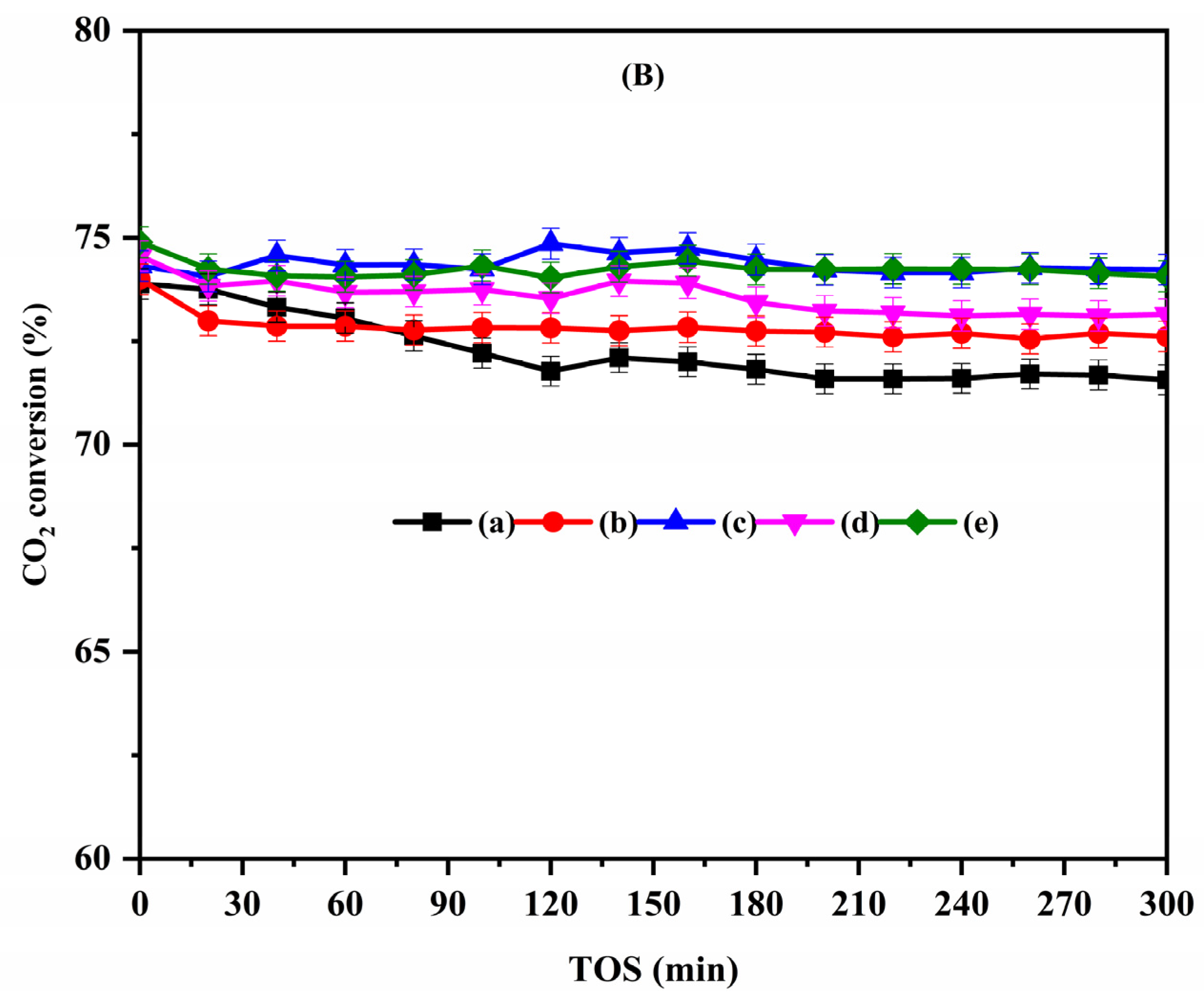
2.2. Catalytic Activity Tests
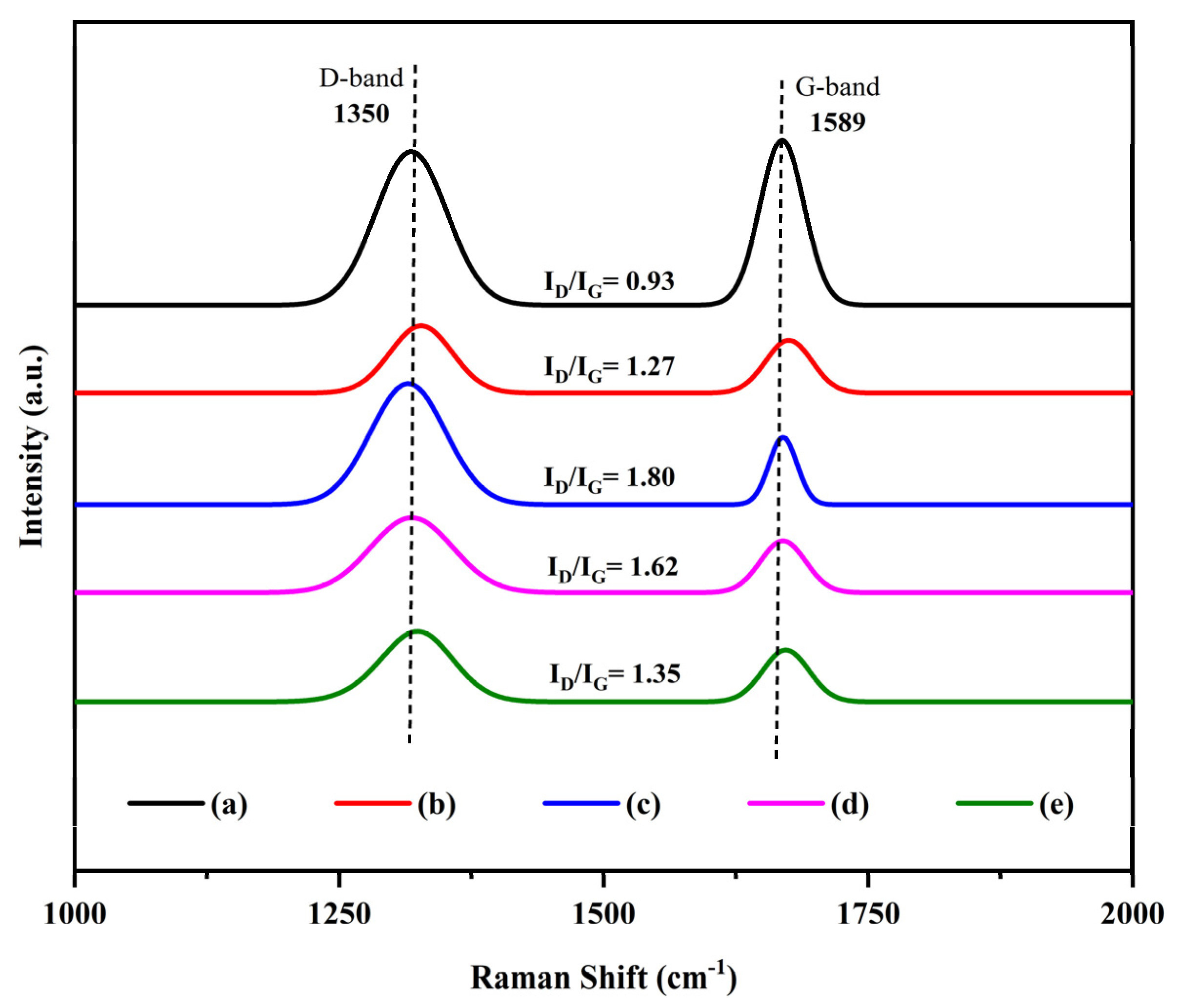
2.3. Characterization of Spent Catalysts
2.4. DFT Mechanistic Insights on the Effect of Ga Modification
3. Materials and Methods
3.1. Catalyst Preparation
3.2. Catalyst Characterization
3.3. Catalytic Activity Performance
3.4. DFT Calculations
4. Conclusions
Supplementary Materials
Author Contributions
Funding
Data Availability Statement
Acknowledgments
Conflicts of Interest
References
- Yentekakis, I.V.; Panagiotopoulou, P.; Artemakis, G. A review of recent efforts to promote dry reforming of methane (DRM) to syngas production via bimetallic catalyst formulations. Appl. Catal. B Environ. 2021, 296, 120210. [Google Scholar] [CrossRef]
- Hussien, A.G.S.; Polychronopoulou, K. A Review on the Different Aspects and Challenges of the Dry Reforming of Methane (DRM) Reaction. Nanomaterials 2022, 12, 3400. [Google Scholar] [CrossRef] [PubMed]
- Xu, Z.; Park, E.D. Recent Advances in Coke Management for Dry Reforming of Methane over Ni-Based Catalysts. Catalysts 2024, 14, 176. [Google Scholar] [CrossRef]
- Huang, L.; Li, D.; Tian, D.; Jiang, L.; Li, Z.; Wang, H.; Li, K. Optimization of Ni-Based Catalysts for Dry Reforming of Methane via Alloy Design: A Review. Energy Fuels 2022, 36, 5102–5151. [Google Scholar] [CrossRef]
- Torrez-Herrera, J.J.; Korili, S.A.; Gil, A. Recent progress in the application of Ni-based catalysts for the dry reforming of methane. Catal. Rev. 2023, 65, 1300–1357. [Google Scholar] [CrossRef]
- Nguyen, T.; Luu, C.L.; Phan, H.P.; Nguyen, P.A.; Van Nguyen, T.T. Methane dry reforming over nickel-based catalysts: Insight into the support effect and reaction kinetics. React. Kinet. Mech. Catal. 2020, 131, 707–735. [Google Scholar] [CrossRef]
- Yu, Y.-X.; Yang, J.; Zhu, K.-K.; Sui, Z.-J.; Chen, D.; Zhu, Y.-A.; Zhou, X.-G. High-Throughput Screening of Alloy Catalysts for Dry Methane Reforming. ACS Catal. 2021, 11, 8881–8894. [Google Scholar] [CrossRef]
- Wang, W.-Y.; Wang, G.-C. Ni3X-type alloy catalysts for dry reforming of methane with high catalytic activity and stability: A density functional theory study. Appl. Surf. Sci. 2024, 648, 158958. [Google Scholar] [CrossRef]
- Liu, X.; Jiang, F.; Liu, K.; Zhao, G.; Liu, J.; Xu, H. NiGa nano-alloy for the dry reforming of methane: Influences of Ga alloying with Ni on the catalytic activity and stability. Chem. Eng. J. 2024, 487, 150351. [Google Scholar] [CrossRef]
- Bai, Y.; Sun, K.; Wu, J.; Zhang, M.; Zhao, S.; Kim, Y.D.; Liu, Y.; Gao, J.; Liu, Z.; Peng, Z. The Ga-promoted Ni/CeO2 catalysts for dry reforming of methane with high stability induced by the enhanced CO2 activation. Mol. Catal. 2022, 530, 112577. [Google Scholar] [CrossRef]
- Kim, K.Y.; Lee, J.H.; Lee, H.; Noh, W.Y.; Kim, E.H.; Ra, E.C.; Kim, S.K.; An, K.; Lee, J.S. Layered Double Hydroxide-Derived Intermetallic Ni3GaC0.25 Catalysts for Dry Reforming of Methane. ACS Catal. 2021, 11, 11091–11102. [Google Scholar] [CrossRef]
- Zeng, F.; Wei, B.; Lan, D.; Ge, J. Highly Dispersed NixGay Catalyst and La2O3 Promoter Supported by LDO Nanosheets for Dry Reforming of Methane: Synergetic Catalysis by Ni, Ga, and La2O3. Langmuir 2021, 37, 9744–9754. [Google Scholar] [CrossRef] [PubMed]
- Al-Fatesh, A.S.; Rajput, Y.B.; Bayazed, M.O.; Alrashed, M.M.; Abu-Dahrieh, J.K.; Elnour, A.Y.; Ibrahim, A.A.; Fakeeha, A.H.; Abasaeed, A.E.; Kumar, R. Impact of gallium loading and process conditions on H2 production from dry reforming of methane over Ni/ZrO2-Al2O3 catalysts. Appl. Catal. A Gen. 2024, 681, 119794. [Google Scholar] [CrossRef]
- Al-Fatesh, A.S.; Chava, R.; Alwan, S.M.; Ibrahim, A.A.; Fakeeha, A.H.; Abu-Dahrieh, J.K.; Yagoub Elnour, A.; Abasaeed, A.E.; Al-Othman, O.; Appari, S. Effect of Ga-Promoted on Ni/Zr + Al2O3 Catalysts for Enhanced CO2 Reforming and Process Optimization. Catal. Lett. 2024, 1–19. [Google Scholar] [CrossRef]
- Shabani, S.; Mirkazemi, S.M.; Rezaie, H.; Vahidshad, Y.; Trasatti, S. A comparative study on the thermal stability, textural, and structural properties of mesostructured γ-Al2O3 granules in the presence of La, Sn, and B additives. Ceram. Int. 2022, 48, 6638–6648. [Google Scholar] [CrossRef]
- Alreshaidan, S.B.; Ibrahim, A.A.; Fakeeha, A.H.; Almutlaq, A.M.; Ali, F.A.A.; Al-Fatesh, A.S. Effect of Modified Alumina Support on the Performance of Ni-Based Catalysts for CO2 Reforming of Methane. Catalysts 2022, 12, 1066. [Google Scholar] [CrossRef]
- Gao, X.; Ge, Z.; Zhu, G.; Wang, Z.; Ashok, J.; Kawi, S. Anti-Coking and Anti-Sintering Ni/Al2O3 Catalysts in the Dry Reforming of Methane: Recent Progress and Prospects. Catalysts 2021, 11, 1003. [Google Scholar] [CrossRef]
- Ahmed, W.; Noor El-Din, M.R.; Aboul-Enein, A.A.; Awadallah, A.E. Effect of textural properties of alumina support on the catalytic performance of Ni/Al2O3 catalysts for hydrogen production via methane decomposition. J. Nat. Gas Sci. Eng. 2015, 25, 359–366. [Google Scholar] [CrossRef]
- Bang, S.; Hong, E.; Baek, S.W.; Shin, C.-H. Effect of acidity on Ni catalysts supported on P-modified Al2O3 for dry reforming of methane. Catal. Today 2018, 303, 100–105. [Google Scholar] [CrossRef]
- Pereira, S.C.; Ribeiro, M.F.; Batalha, N.; Pereira, M.M. Catalyst regeneration using CO2 as reactant through reverse-Boudouard reaction with coke. Greenh. Gases Sci. Technol. 2017, 7, 843–851. [Google Scholar] [CrossRef]
- Osaki, T.; Mori, T. Kinetics of the reverse-Boudouard reaction over supported nickel catalysts. React. Kinet. Catal. Lett. 2006, 89, 333–339. [Google Scholar] [CrossRef]
- Park, H.-R.; Kim, B.-J.; Lee, Y.-L.; Ahn, S.-Y.; Kim, K.-J.; Hong, G.-R.; Yun, S.-J.; Jeon, B.-H.; Bae, J.W.; Roh, H.-S. CO2 Reforming of CH4 Using Coke Oven Gas over Ni/MgO-Al2O3 Catalysts: Effect of the MgO:Al2O3 Ratio. Catalysts 2021, 11, 1468. [Google Scholar] [CrossRef]
- Kim, B.-J.; Park, H.-R.; Lee, Y.-L.; Ahn, S.-Y.; Kim, K.-J.; Hong, G.-R.; Roh, H.-S. Effect of surface properties of Ni-MgO-Al2O3 catalyst for simultaneous H2 production and CO2 utilization using dry reforming of coke oven gas. Catal. Today 2023, 411–412, 113855. [Google Scholar] [CrossRef]
- Jin, B.; Li, S.; Liang, X. Enhanced activity and stability of MgO-promoted Ni/Al2O3 catalyst for dry reforming of methane: Role of MgO. Fuel 2021, 284, 119082. [Google Scholar] [CrossRef]
- Charisiou, N.D.; Papageridis, K.N.; Tzounis, L.; Sebastian, V.; Hinder, S.J.; Baker, M.A.; AlKetbi, M.; Polychronopoulou, K.; Goula, M.A. Ni supported on CaO-MgO-Al2O3 as a highly selective and stable catalyst for H2 production via the glycerol steam reforming reaction. Int. J. Hydrogen Energy 2019, 44, 256–273. [Google Scholar] [CrossRef]
- Basile, F.; Benito, P.; Fornasari, G.; Vaccari, A. Hydrotalcite-type precursors of active catalysts for hydrogen production. Appl. Clay Sci. 2010, 48, 250–259. [Google Scholar] [CrossRef]
- Long, H.; Xu, Y.; Zhang, X.; Hu, S.; Shang, S.; Yin, Y.; Dai, X. Ni-Co/Mg-Al catalyst derived from hydrotalcite-like compound prepared by plasma for dry reforming of methane. J. Energy Chem. 2013, 22, 733–739. [Google Scholar] [CrossRef]
- Abbas, M.; Sikander, U.; Mehran, M.T.; Kim, S.H. Exceptional stability of hydrotalcite derived spinel Mg(Ni)Al2O4 catalyst for dry reforming of methane. Catal. Today 2022, 403, 74–85. [Google Scholar] [CrossRef]
- Dębek, R.; Motak, M.; Duraczyska, D.; Launay, F.; Galvez, M.E.; Grzybek, T.; Da Costa, P. Methane dry reforming over hydrotalcite-derived Ni–Mg–Al mixed oxides: The influence of Ni content on catalytic activity, selectivity and stability. Catal. Sci. Technol. 2016, 6, 6705–6715. [Google Scholar] [CrossRef]
- Pérez-Ramírez, J.; Mul, G.; Moulijn, J.A. In situ Fourier transform infrared and laser Raman spectroscopic study of the thermal decomposition of Co–Al and Ni–Al hydrotalcites. Vib. Spectrosc. 2001, 27, 75–88. [Google Scholar] [CrossRef]
- Wiyantoko, B.; Kurniawati, P.; Purbaningtias, T.E.; Fatimah, I. Synthesis and Characterization of Hydrotalcite at Different Mg/Al Molar Ratios. Procedia Chem. 2015, 17, 21–26. [Google Scholar] [CrossRef]
- Cavani, F.; Trifirò, F.; Vaccari, A. Hydrotalcite-type anionic clays: Preparation, properties and applications. Catal. Today 1991, 11, 173–301. [Google Scholar] [CrossRef]
- Dębek, R.; Zubek, K.; Motak, M.; Da Costa, P.; Grzybek, T. Effect of nickel incorporation into hydrotalcite-based catalyst systems for dry reforming of methane. Res. Chem. Intermed. 2015, 41, 9485–9495. [Google Scholar] [CrossRef]
- Thommes, M.; Kaneko, K.; Neimark, A.V.; Olivier, J.P.; Rodriguez-Reinoso, F.; Rouquerol, J.; Sing, K.S.W. Physisorption of gases, with special reference to the evaluation of surface area and pore size distribution (IUPAC Technical Report). Pure Appl. Chem. 2015, 87, 1051–1069. [Google Scholar] [CrossRef]
- Jayaprakash, S.; Dewangan, N.; Jangam, A.; Das, S.; Kawi, S. LDH-derived Ni–MgO–Al2O3 catalysts for hydrogen-rich syngas production via steam reforming of biomass tar model: Effect of catalyst synthesis methods. Int. J. Hydrogen Energy 2021, 46, 18338–18352. [Google Scholar] [CrossRef]
- Abdelsadek, Z.; Holgado, J.P.; Halliche, D.; Caballero, A.; Cherifi, O.; Gonzalez-Cortes, S.; Masset, P.J. Examination of the Deactivation Cycle of NiAl- and NiMgAl-Hydrotalcite Derived Catalysts in the Dry Reforming of Methane. Catal. Lett. 2021, 151, 2696–2715. [Google Scholar] [CrossRef]
- Zotin, F.M.Z.; Tournayan, L.; Varloud, J.; Perrichon, V.; Fréty, R. Temperature-programmed reduction: Limitation of the technique for determining the extent of reduction of either pure ceria or ceria modified by additives. Appl. Catal. A Gen. 1993, 98, 99–114. [Google Scholar] [CrossRef]
- Kim, S.M.; Abdala, P.M.; Margossian, T.; Hosseini, D.; Foppa, L.; Armutlulu, A.; van Beek, W.; Comas-Vives, A.; Copéret, C.; Müller, C. Cooperativity and Dynamics Increase the Performance of NiFe Dry Reforming Catalysts. J. Am. Chem. Soc. 2017, 139, 1937–1949. [Google Scholar] [CrossRef]
- Guo, J.; Lou, H.; Zhao, H.; Chai, D.; Zheng, X. Dry reforming of methane over nickel catalysts supported on magnesium aluminate spinels. Appl. Catal. A Gen. 2004, 273, 75–82. [Google Scholar] [CrossRef]
- Kang, K.; Kakihara, S.; Higo, T.; Sampei, H.; Saegusa, K.; Sekine, Y. Equilibrium unconstrained low-temperature CO2 conversion on doped gallium oxides by chemical looping. Chem. Commun. 2023, 59, 11061–11064. [Google Scholar] [CrossRef]
- Kwon, D.; Kang, J.Y.; An, S.; Yang, I.; Jung, J.C. Tuning the base properties of Mg–Al hydrotalcite catalysts using their memory effect. J. Energy Chem. 2020, 46, 229–236. [Google Scholar] [CrossRef]
- Tsyganok, A.I.; Tsunoda, T.; Hamakawa, S.; Suzuki, K.; Takehira, K.; Hayakawa, T. Dry reforming of methane over catalysts derived from nickel-containing Mg–Al layered double hydroxides. J. Catal. 2003, 213, 191–203. [Google Scholar] [CrossRef]
- Wang, L.; Li, F.; Chen, Y.; Chen, J. Selective hydrogenation of acetylene on SiO2-supported Ni-Ga alloy and intermetallic compound. J. Energy Chem. 2019, 29, 40–49. [Google Scholar] [CrossRef]
- Sharafutdinov, I.; Elkjær, C.F.; Pereira de Carvalho, H.W.; Gardini, D.; Chiarello, G.L.; Damsgaard, C.D.; Wagner, J.B.; Grunwaldt, J.-D.; Dahl, S.; Chorkendorff, I. Intermetallic compounds of Ni and Ga as catalysts for the synthesis of methanol. J. Catal. 2014, 320, 77–88. [Google Scholar] [CrossRef]
- López-Asensio, R.; Cecilia-Buenestado, J.A.; Herrera-Delgado, C.; Larrubia-Vargas, M.Á.; García-Sancho, C.; Maireles-Torres, P.J.; Moreno-Tost, R. Mixed Oxides Derived from Hydrotalcites Mg/Al Active in the Catalytic Transfer Hydrogenation of Furfural to Furfuryl Alcohol. Catalysts 2023, 13, 45. [Google Scholar] [CrossRef]
- Stepanova, L.N.; Kobzar, E.O.; Trenikhin, M.V.; Leont’eva, N.N.; Serkova, A.N.; Salanov, A.N.; Lavrenov, A.V. Catalysts Based on Ni(Mg)Al-Layered Hydroxides Prepared by Mechanical Activation for Furfural Hydrogenation. Catalysts 2023, 13, 497. [Google Scholar] [CrossRef]
- Miguel, C.V.; Trujillano, R.; Rives, V.; Vicente, M.A.; Ferreira, A.F.P.; Rodrigues, A.E.; Mendes, A.; Madeira, L.M. High temperature CO2 sorption with gallium-substituted and promoted hydrotalcites. Sep. Purif. Technol. 2014, 127, 202–211. [Google Scholar] [CrossRef]
- Yavuz, C.T.; Shinall, B.D.; Iretskii, A.V.; White, M.G.; Golden, T.; Atilhan, M.; Ford, P.C.; Stucky, G.D. Markedly Improved CO2 Capture Efficiency and Stability of Gallium Substituted Hydrotalcites at Elevated Temperatures. Chem. Mater. 2009, 21, 3473–3475. [Google Scholar] [CrossRef]
- Guo, J.; Lou, H.; Zheng, X. The deposition of coke from methane on a Ni/MgAl2O4 catalyst. Carbon 2007, 45, 1314–1321. [Google Scholar] [CrossRef]
- Wang, P.; Tanabe, E.; Ito, K.; Jia, J.; Morioka, H.; Shishido, T.; Takehira, K. Filamentous carbon prepared by the catalytic pyrolysis of CH4 on Ni/SiO2. Appl. Catal. A Gen. 2002, 231, 35–44. [Google Scholar] [CrossRef]
- Akri, M.; El Kasmi, A.; Batiot-Dupeyrat, C.; Qiao, B. Highly Active and Carbon-Resistant Nickel Single-Atom Catalysts for Methane Dry Reforming. Catalysts 2020, 10, 630. [Google Scholar] [CrossRef]
- Zimmerli, N.K.; Rochlitz, L.; Checchia, S.; Müller, C.R.; Copéret, C.; Abdala, P.M. Structure and Role of a Ga-Promoter in Ni-Based Catalysts for the Selective Hydrogenation of CO2 to Methanol. JACS Au 2024, 4, 237–252. [Google Scholar] [CrossRef] [PubMed]
- Li, C.; Chen, Y.; Zhang, S.; Zhou, J.; Wang, F.; He, S.; Wei, M.; Evans, D.G.; Duan, X. Nickel–Gallium Intermetallic Nanocrystal Catalysts in the Semihydrogenation of Phenylacetylene. ChemCatChem 2014, 6, 824–831. [Google Scholar] [CrossRef]
- Rao, D.-M.; Zhang, S.-T.; Li, C.-M.; Chen, Y.-D.; Pu, M.; Yan, H.; Wei, M. The reaction mechanism and selectivity of acetylene hydrogenation over Ni-Ga intermetallic compound catalysts: A density functional theory study. Dalton Trans. 2018, 47, 4198–4208. [Google Scholar] [CrossRef]
- Chang, Y.K.; Lin, K.P.; Pong, W.F.; Tsai, M.-H.; Hseih, H.H.; Pieh, J.Y.; Tseng, P.K.; Lee, J.F.; Hsu, L.S. Charge transfer and hybridization effects in Ni3Al and Ni3Ga studies by x-ray-absorption spectroscopy and theoretical calculations. J. Appl. Phys. 2000, 87, 1312–1317. [Google Scholar] [CrossRef]
- Kresse, G.; Hafner, J. Ab initio molecular dynamics for open-shell transition metals. Phys. Rev. B 1993, 48, 13115–13118. [Google Scholar] [CrossRef]
- Kresse, G.; Furthmüller, J. Efficiency of ab-initio total energy calculations for metals and semiconductors using a plane-wave basis set. Comput. Mater. Sci. 1996, 6, 15–50. [Google Scholar] [CrossRef]
- Kohn, W.; Sham, L.J. Self-Consistent Equations Including Exchange and Correlation Effects. Phys. Rev. 1965, 140, A1133–A1138. [Google Scholar] [CrossRef]
- Perdew, J.P.; Burke, K.; Ernzerhof, M. Generalized Gradient Approximation Made Simple. Phys. Rev. Lett. 1996, 77, 3865–3868. [Google Scholar] [CrossRef]
- Kresse, G.; Joubert, D. From ultrasoft pseudopotentials to the projector augmented-wave method. Phys. Rev. B 1999, 59, 1758–1775. [Google Scholar] [CrossRef]
- Blöchl, P.E. Projector augmented-wave method. Phys. Rev. B 1994, 50, 17953–17979. [Google Scholar] [CrossRef] [PubMed]
- Monkhorst, H.J.; Pack, J.D. Special points for Brillouin-zone integrations. Phys. Rev. B 1976, 13, 5188–5192. [Google Scholar] [CrossRef]
- Al-Fatesh, A.S.; Ibrahim, A.A.; Abu-Dahrieh, J.K.; Al-Awadi, A.S.; El-Toni, A.M.; Fakeeha, A.H.; Abasaeed, A.E. Gallium-Promoted Ni Catalyst Supported on MCM-41 for Dry Reforming of Methane. Catalysts 2018, 8, 229. [Google Scholar] [CrossRef]
- Fakeeha, A.H.; Kurdi, A.; Al-Baqmaa, Y.A.; Ibrahim, A.A.; Abasaeed, A.E.; Al-Fatesh, A.S. Performance Study of Methane Dry Reforming on Ni/ZrO2 Catalyst. Energies 2022, 15, 3841. [Google Scholar] [CrossRef]
- Al-Fatesh, A.S.; Fakeeha, A.H.; Ibrahim, A.A.; Abasaeed, A.E. Ni supported on La2O3+ZrO2 for dry reforming of methane: The impact of surface adsorbed oxygen species. Int. J. Hydrogen Energy 2021, 46, 3780–3788. [Google Scholar] [CrossRef]
- Pan, Y.-x.; Kuai, P.; Liu, Y.; Ge, Q.; Liu, C.-j. Promotion effects of Ga2O3 on CO2 adsorption and conversion over a SiO2-supported Ni catalyst. Energy Environ. Sci. 2010, 3, 1322–1325. [Google Scholar] [CrossRef]


| Sample | Surface Area (m2/g) | Pore Volume (cm3) | Pore Size (nm) | |||
|---|---|---|---|---|---|---|
| As-Prepared | Calcined | As-Prepared | Calcined | As-Prepared | Calcined | |
| Ni/(Mg, Al)Ox | 131.2 | 215.4 | 0.51 | 0.68 | 14.2 | 12.4 |
| Ni-Ga/(Mg, Al)Ox (Ga/Ni = 0.1) | 124.2 | 205.7 | 0.55 | 0.73 | 16.8 | 15.4 |
| Ni-Ga/(Mg, Al)Ox (Ga/Ni = 0.3) | 150.4 | 189.9 | 0.66 | 0.70 | 16.6 | 15.4 |
| Ni-Ga/(Mg, Al)Ox (Ga/Ni = 0.5) | 122.2 | 197.7 | 0.59 | 0.80 | 17.8 | 17.0 |
| Ni-Ga/(Mg, Al)Ox (Ga/Ni = 1.0) | 150.4 | 253.1 | 0.64 | 0.96 | 15.9 | 15.6 |
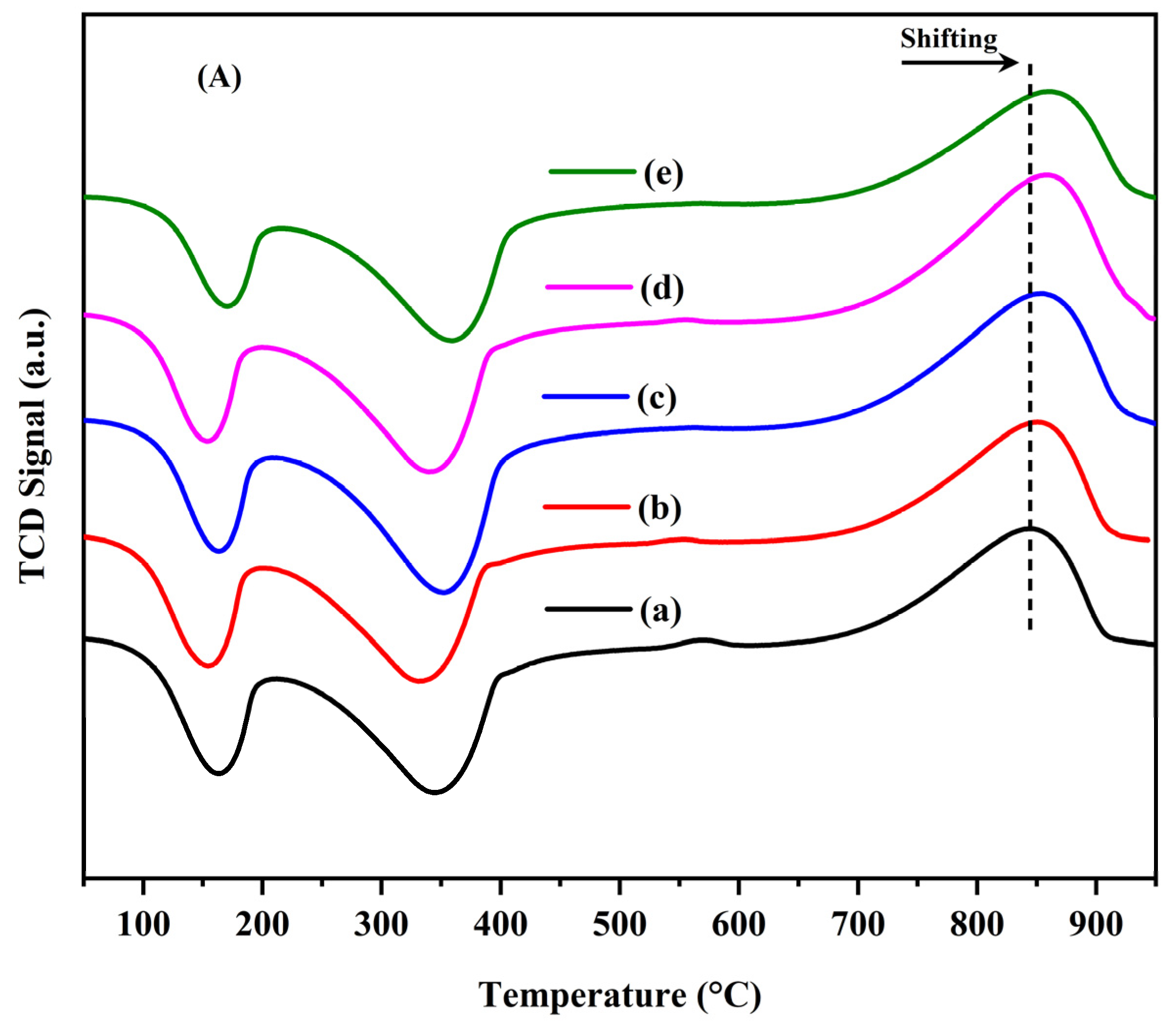
| HT Sample | Peak Temperature (°C) | Total H2 Consumed (mmol/gcat) a |
|---|---|---|
| Ni/(Mg, Al) | 845 | 0.92 |
| Ni-Ga/(Mg, Al) (Ga/Ni = 0.1) | 851 | 0.95 |
| Ni-Ga/(Mg, Al) (Ga/Ni = 0.3) | 855 | 1.35 |
| Ni-Ga/(Mg, Al) (Ga/Ni = 0.5) | 858 | 1.10 |
| Ni-Ga/(Mg, Al) (Ga/Ni = 1.0) | 860 | 1.21 |
Disclaimer/Publisher’s Note: The statements, opinions and data contained in all publications are solely those of the individual author(s) and contributor(s) and not of MDPI and/or the editor(s). MDPI and/or the editor(s) disclaim responsibility for any injury to people or property resulting from any ideas, methods, instructions or products referred to in the content. |
© 2024 by the authors. Licensee MDPI, Basel, Switzerland. This article is an open access article distributed under the terms and conditions of the Creative Commons Attribution (CC BY) license (https://creativecommons.org/licenses/by/4.0/).
Share and Cite
Elnour, A.Y.; Abasaeed, A.E.; Fakeeha, A.H.; Ibrahim, A.A.; Alreshaidan, S.B.; Al-Fatesh, A.S. Dry Reforming of Methane (DRM) over Hydrotalcite-Based Ni-Ga/(Mg, Al)Ox Catalysts: Tailoring Ga Content for Improved Stability. Catalysts 2024, 14, 721. https://doi.org/10.3390/catal14100721
Elnour AY, Abasaeed AE, Fakeeha AH, Ibrahim AA, Alreshaidan SB, Al-Fatesh AS. Dry Reforming of Methane (DRM) over Hydrotalcite-Based Ni-Ga/(Mg, Al)Ox Catalysts: Tailoring Ga Content for Improved Stability. Catalysts. 2024; 14(10):721. https://doi.org/10.3390/catal14100721
Chicago/Turabian StyleElnour, Ahmed Y., Ahmed E. Abasaeed, Anis H. Fakeeha, Ahmed A. Ibrahim, Salwa B. Alreshaidan, and Ahmed S. Al-Fatesh. 2024. "Dry Reforming of Methane (DRM) over Hydrotalcite-Based Ni-Ga/(Mg, Al)Ox Catalysts: Tailoring Ga Content for Improved Stability" Catalysts 14, no. 10: 721. https://doi.org/10.3390/catal14100721
APA StyleElnour, A. Y., Abasaeed, A. E., Fakeeha, A. H., Ibrahim, A. A., Alreshaidan, S. B., & Al-Fatesh, A. S. (2024). Dry Reforming of Methane (DRM) over Hydrotalcite-Based Ni-Ga/(Mg, Al)Ox Catalysts: Tailoring Ga Content for Improved Stability. Catalysts, 14(10), 721. https://doi.org/10.3390/catal14100721