Abstract
Nitrogen-doped graphene has been increasingly utilized in a variety of energy-related applications, serving as a catalyst or support material for fuel cells, and as an anode material for lithium-ion batteries, among others. The thermal reduction of graphene oxide (GO) in nitrogenous sources to incorporate nitrogen, producing nitrogen-doped reduced graphene oxide (NRGO), is the most favored method. Controlling atomic configurations of nitrogen-doped sites is the key factor for tailoring the physico-chemical properties of NRGO, but major challenges remain in identifying detailed atomic arrangements at nitrogen binding sites on highly defective and chemically functionalized GO surfaces. In this paper, we present atomistic-scale modeling of the nitrogen doping process of GO with different types of vacancy defects. Molecular dynamics simulations using a reactive force field indicate that the edge carbon atoms on defect sites are the dominant initiation location for nitrogen doping. Further, first-principles calculations using density functional theory present energetically favorable chemical transition pathways for nitrogen doping. The significance of this work lies in providing important chemical insights for the effective control of the desired properties of NRGO by suggesting a detailed mechanism of the nitrogen doping process of GO.
1. Introduction
Graphene has been extensively studied for decades as a promising material for a number of physico-chemical applications due to its superior thermal and electrical conductivity [1,2,3,4,5] and its potential possibilities of inexpensive and eco-friendly production [6,7,8,9]. Such applications can be even further broadened by chemical modifications through the doping of heterogeneous atoms such as nitrogen, boron, and sulfur into the sp2 hybridization network. Numerous studies report strategies for synthesizing chemically doped graphene, enabling the design and improvement of chemical applications of graphene-based materials and devices [10,11,12,13,14,15,16,17]. Among various approaches, the atomistic introduction of nitrogen into graphene is a powerful and widespread technique for tailoring the physico-chemical properties of graphene by increasing the charge populations of the hybridization network [18,19,20,21]. In particular, the thermal treatment of graphene oxide (GO) with a nitrogen-containing reducing agent such as ammonia, hydrazine, or melamine effectively produces nitrogen-doped reduced graphene oxide (NRGO). This method has proven to be efficient on a batch scale and has gained popularity in catalytic and electronic applications due to its effectiveness and simplicity [22,23,24].
Nitrogen contents (1 to 10 atomic %) and types (amine, pyrrolic, pyridinic, and graphitic) in NRGO are known to be dependent on the reduction conditions, including the reducing reagent, temperature, and time [19,20,23,25,26]. Qualitatively, incorporating more energy is required to form more C-N bonds in the graphene network while breaking C-C bonds within the graphene and N-H bonds of ammonia. Consequently, the graphitic site requires the highest energy for its formation. Therefore, sufficient thermal energy and reaction time are crucial for nitrogen atoms to be impregnated into the graphene network by overcoming several reaction barriers, resulting in the desired composition of nitrogen-doped sites, from amine to graphitic. These doping states of nitrogen atoms control the electronic structure of NRGO, which significantly affects its catalytic activity and selectivity [27,28]. Thus, a well-controlled nitrogen doping technique is essential for practical applications of NRGO as a tailored material for specific purposes.
Several efforts to control nitrogen doping sites in highly ordered graphene materials have been reported [16,17,29]. However, controlling and analyzing the nitrogen doping process in GO, which involves the reduction of oxygen-bound and vacancy defect sites, poses more challenges due to its defective and poorly ordered structures [30,31]. Additionally, numerous experimental and theoretical studies have explored the bonding natures and evolution of nitrogen-doped sites on pure graphene [32,33,34,35]. Recent research has highlighted that defects in the conjugated graphene network significantly influence the N-doping mechanism and, consequently, the doping efficiency of the material [36,37,38,39]. Nonetheless, a few studies have delved into a comprehensive understanding of the doping mechanisms of NRGO at the atomistic scale [40]. To achieve precisely controlled nitrogen doping sites and enhance the physico-chemical properties of NRGO as desired, a detailed chemical overview of the nitrogen doping process is essential.
In this study, we conducted large-scale atomistic molecular dynamics (MD) simulations based on the reactive force field (ReaxFF) to directly investigate the doping mechanism of nitrogen into GO structures with various carbon vacancy defects. ReaxFF, an empirical bond-order-based potential, is well-known for modeling the chemical reaction dynamics of large systems. Successful thermodynamic descriptions of bond formation and breakage with ReaxFF reveal the overall atomistic behaviors of the doping process in terms of vacancy defect sizes and exposed carbon sites. Additional density functional theory (DFT) calculations provide detailed thermodynamic descriptions of different nitrogen doping sites observed from MD results.
2. Results and Discussions
2.1. Nitrogen Doping Behaviors from ReaxFF Simulations
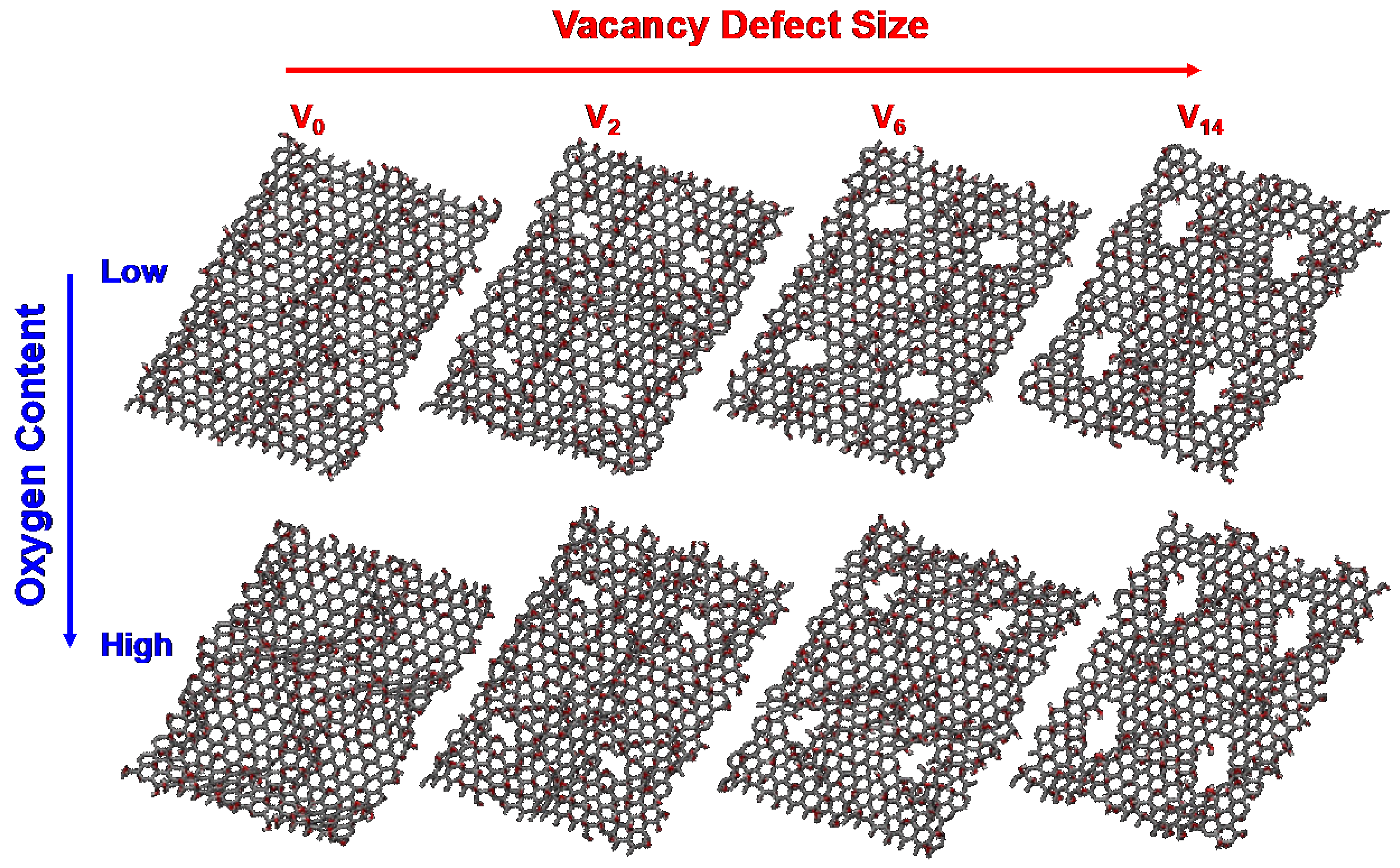
Atomistic GO models with different sizes of carbon vacancy and the contents of oxygen functional groups are prepared as shown in Figure 1. A unit rectangular graphene sheet with 192 carbon atoms is prepared, followed by a random distribution of epoxy and hydroxyl groups on both the top and bottom sides of the graphene sheet at a ratio of 1:1. Two different GO templates with varying oxygen contents are tested in this work, namely, low-GO and high-GO (30 and 40 atomic % of O/C ratio, respectively). Carbon vacancy defects of four different sizes are introduced for each GO template (V0: no-, V2: di-, V6: hexa-, and V14: tetradeca-carbon vacancies). These GO models are duplicated into a 2 × 2 array in the x-y plane to increase the number of available defective sites for nitrogen doping. The final atomistic GO models with no defects, di-vacancy, hexa-vacancy, and tetradeca-vacancy contain 768, 760, 744, and 712 carbon atoms, respectively. The GO models with different defect sites and oxygen contents are first thermally annealed at 1000 K under a H2 environment to remove and stabilize unstable functional groups. This procedure produces chemically realistic surface structures for subsequent simulations. The resulting GO models contain 22–25 atomic % and 32–35 atomic % of oxygen for the low-GO and high-GO models, respectively. These structures are then reduced with NH3 molecules at 1000 K to simulate oxygen reduction and nitrogen doping reactions. This stepwise approach ensures a comprehensive understanding of how different defect sizes and oxygen content levels influence the efficiency and distribution of nitrogen doping, providing key insights into optimizing the preparation of NRGO for specific applications.
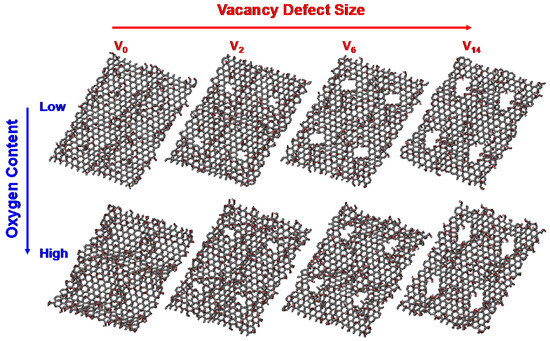
Figure 1.
Atomistic GO models with two different oxygen contents and four different carbon vacancy defects used in ReaxFF simulations.
ReaxFF MD trajectories are analyzed to monitor the bond connectivity between atoms with simulation time (Figure 2). The oxygen content consistently decreases to around 15 atomic % for all GO substrates, regardless of the inherent structural characteristics of the GO models (Figure 2a,c). This trend suggests that the reduction process of GO is successfully simulated, reflecting a continuous thermally driven removal of oxygen functional groups as water molecules by ammonia gas. On the other hand, the nitrogen doping levels are mainly influenced by the size of vacancy defects; larger defects lead to a higher nitrogen content due to the increased availability of reactive edge carbon sites (Figure 2b,d). These results indicate that defect size plays a more critical role in the nitrogen doping process than the initial oxygen content. However, it is noteworthy that the measured nitrogen doping ratio (<1 atomic %) is relatively lower than experimentally measured values [15]. This difference could be primarily attributed to the differing reaction environments between the experimental procedure and the theoretical model. For example, the simulation does not account for the continuous removal of generated H2O molecules nor the replenishment with new NH3 molecules, which would significantly influence the equilibrium towards nitrogen doping. Additionally, more active doping sites, such as vacancy defects, edge carbons, and dangling carbons, are expected to be available in realistic GO materials.
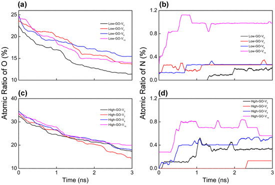
Figure 2.
Temporal evolutions of atomic percent ratio of (a,c) oxygen and (b,d) nitrogen bound on each GO model during the ReaxFF simulations under NH3 at 1000 K.
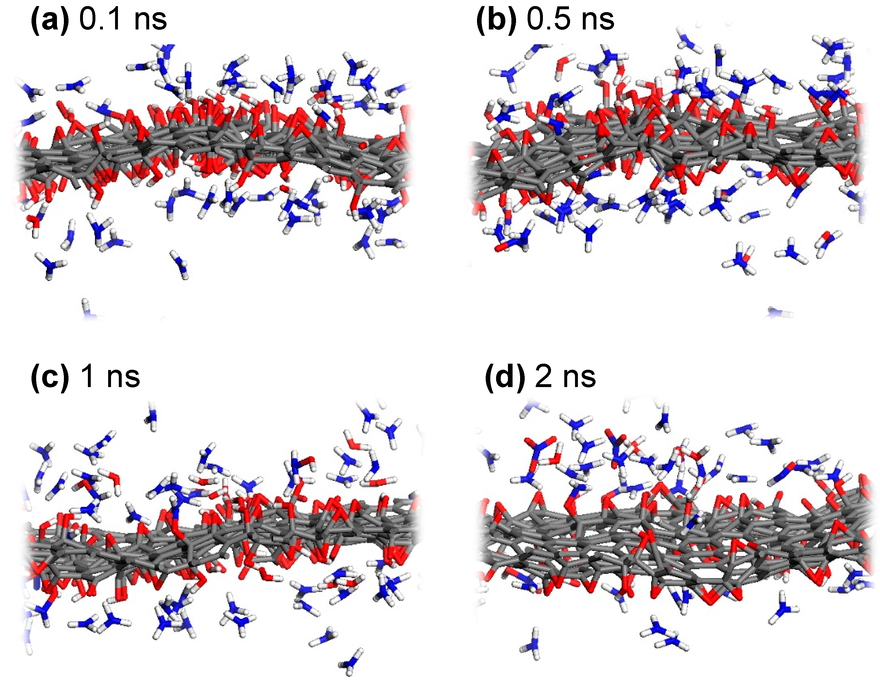
To observe the reaction dynamics of the nitrogen doping process from NH3 into GO, snapshots from NVT dynamics trajectories for the low-GO-V14 structure are shown in Figure 3. Since ReaxFF is adept at describing hydrogen bonding [41], the non-covalent interactions between ammonia molecules and oxygen-containing functional groups in GO are well captured. These interactions are predominantly observed early in the reduction process, prior to the gradual reduction and desorption of oxygen atoms (Figure 3a,b). The favorable hydrogen bonding between NH3 molecules and GO leads to increased collision events, which, in turn, facilitates the hydrogenation of carbon-bound oxygen, thus enabling the activation of nitrogen to form carbon-bound nitrogen. More specifically, the sufficient thermal energy and the reductive environment provided by thermally activated ammonia contribute to the detachment of oxygen, primarily as H2O, by converting epoxy to hydroxyl and, subsequently, to H2O (Figure 3c,d). Additionally, O2, N2, NO3−, HNO, N2H4, and several radical species are produced during the reduction of oxygen-containing functional groups. As mentioned earlier, a significant portion of the H2O molecules remains on the GO surface and is likely to reverse the chemical equilibrium, potentially leading to a lower nitrogen doping yield compared to experimental observations.
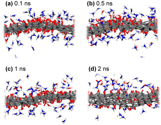
Figure 3.
Representative snapshots during the ReaxFF MD simulation of low-GO-V14 with NH3, captured at (a) 0.1 ns, (b) 0.5 ns, (c) 1 ns, and (d) 2 ns of NVT dynamics at 1000 K.
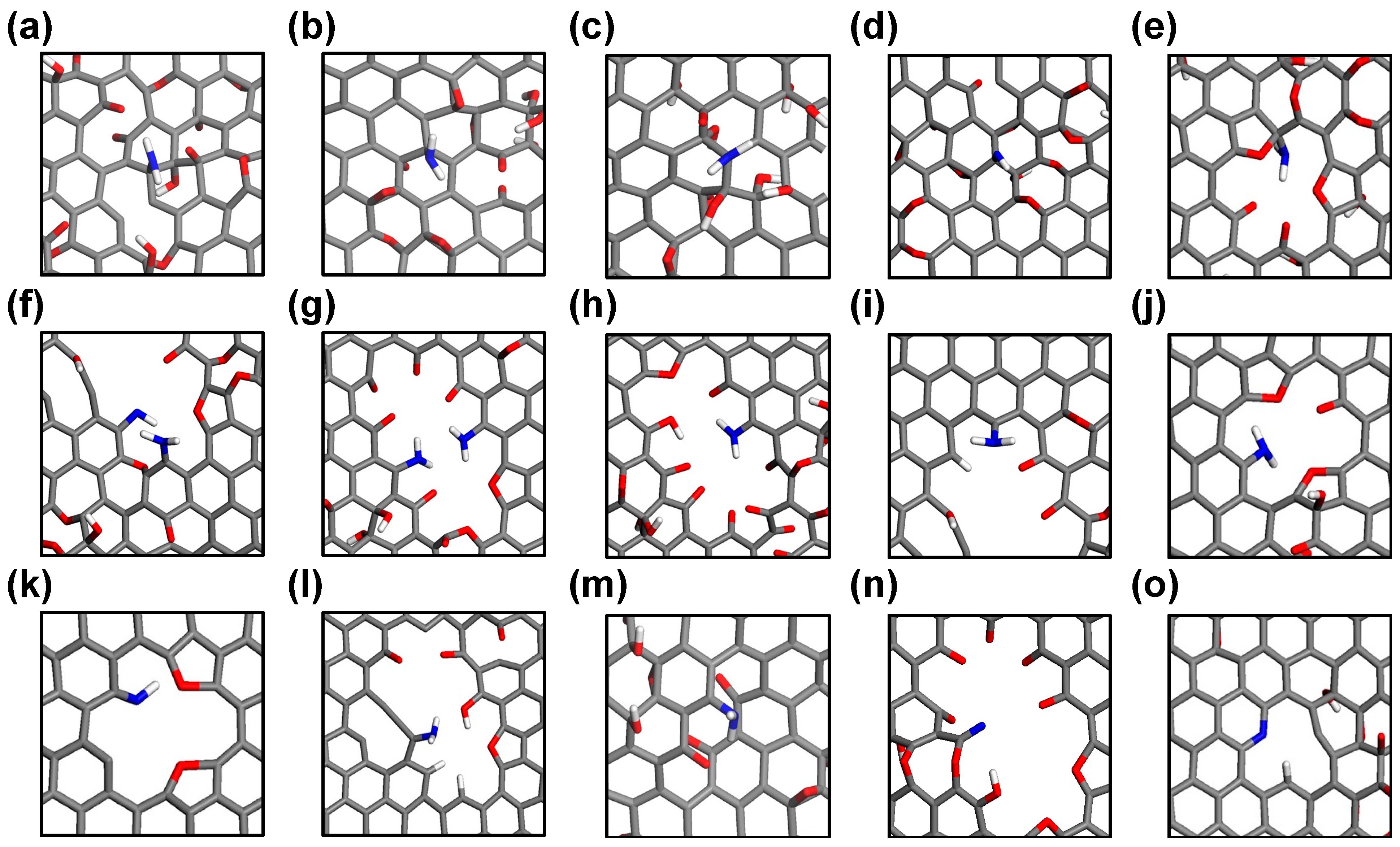
Various nitrogen-doped sites are observed during the ReaxFF MD trajectories and are visualized in Figure 4. Essentially, the carbon sites from which oxygen-containing functional groups have been detached, whether from basal planes or defect sites, can serve as potential initial doping sites for amidogen radicals (·NH2). Interestingly, nitrogen atoms bound on the basal graphene plane are observed only in defect-free structures (low- and high-GO-V0, Figure 4a–d), whereas most nitrogen doping events occur at defective edge carbon sites when vacancy defects are present (Figure 4e–o). This indicates that amidogen radicals, or ions such as amine anion (NH2−), preferentially bind with defective edge carbons rather than sp2-conjugated basal carbons. A detailed examination of all nitrogen-doped sites reveals that most are –NH2 or –NH configurations, representing the initial states of nitrogen doping (Figure 4a–m). Furthermore, fully reduced nitrogen sites are also identified, including an unbound –CN and a tertiary pyridinic nitrogen at a di-vacancy defect site (Figure 4n and Figure 4o, respectively). We postulate that the reason most initially doped amine groups do not structurally evolve to form typical pyridinic and graphitic sites, even in defect models, is due to deviations from real experimental conditions, such as the limited atomic configurations, reduction time, and partial pressure of the reducing agent. Our simulation results suggest that amine groups doped onto the perfect basal graphene are unlikely to disrupt the sp2 conjugation or to be incorporated into the stable in-plane carbon network. However, it is important to note that most nitrogen doping events, as a final state, occur at defective edge sites, which offer ample space for nitrogen atoms to interact with the reactive carbon sites.
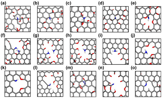
Figure 4.
Snapshots of nitrogen-doped sites on various GO templates from ReaxFF MD trajectories. (a–d) Amine on basal planes, (e–m) amine at defect sites, (n) unbound –CN, and (o) pyridinic nitrogen at defect site.
2.2. Detailed Thermodynamics of Nitrogen Doping
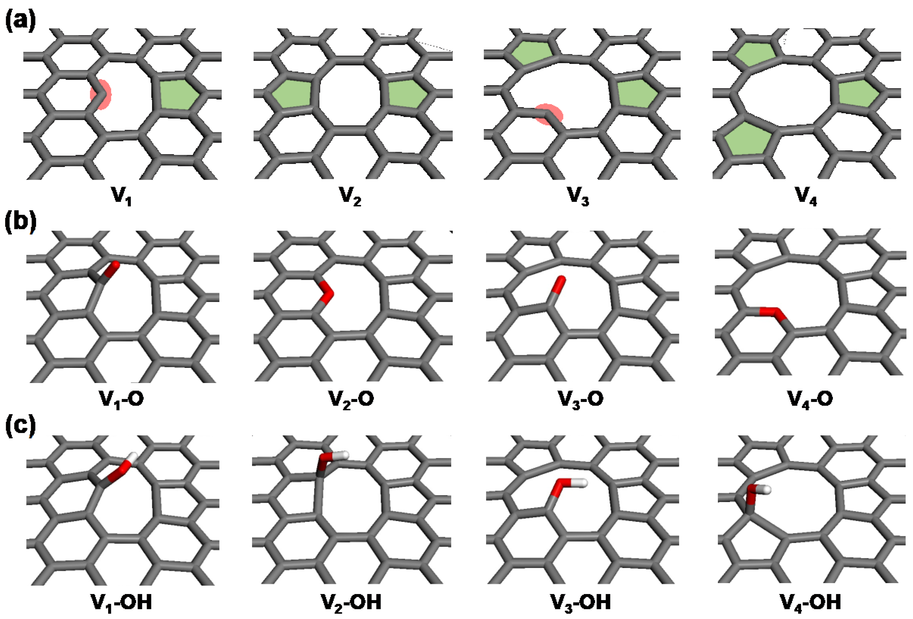
Analyses of the ReaxFF MD results indicate that reactive and spacious defective edge carbon atoms serve as the primary sites for nitrogen doping. To delve into the detailed thermodynamics associated with the incorporation and evolution of nitrogen during the synthesis process of NRGO, DFT calculations were conducted on four simplified basal graphene structures with vacancy defects ranging from one to four carbon atoms (V1 to V4). The presence of carbon vacancies results in the emergence of various configurations of dangling carbon and topological defects in the bare models (Vn, where n = 1 to 4, as shown in Figure 5a). In both oxygen- and hydroxyl-functionalized structures, an oxygen functional group (–O or –OH) is added to either the dangling carbons or the pentagonal topological defect sites for each model (Vn–O and Vn–OH, as depicted in Figure 5b,c). These are the most stable binding sites identified for each configuration, chosen to reasonably model the primary pathways for nitrogen doping. Single oxygen functionalization at V2 and V4 sites leads to the formation of in-plane embedded ether groups, whereas the V1 and V3 models result in the formation of carbonyl groups at the dangling carbon sites.
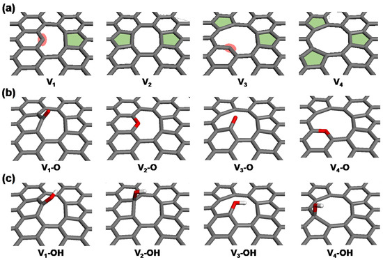
Figure 5.
Simplified GO models with carbon vacancies (Vn), showing (a) bare, (b) oxygen-functionalized (Vn–O), and (c) hydroxyl-functionalized (Vn–OH) configurations.
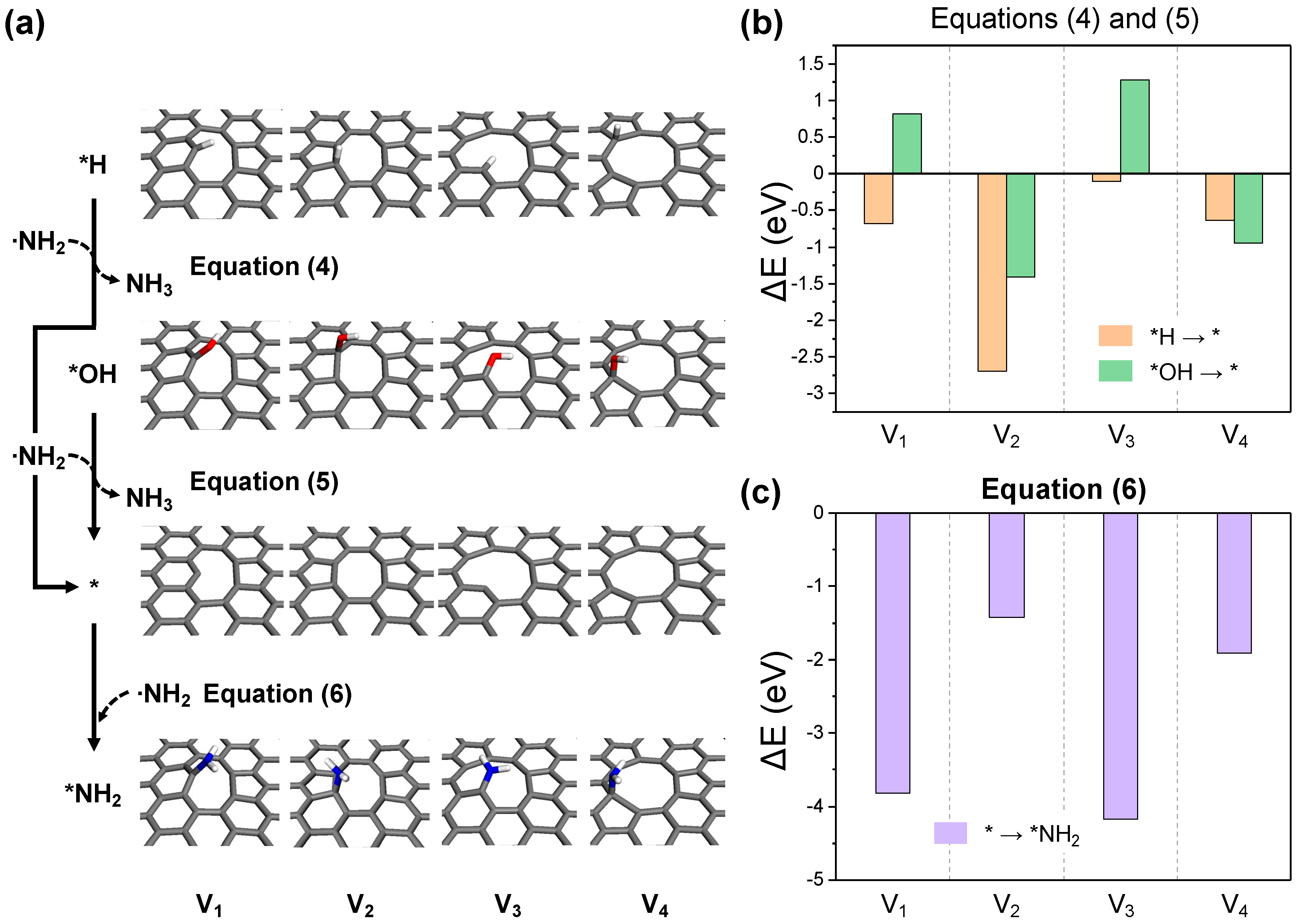
To systematically analyze the nitrogen doping process facilitated by ammonia molecules, the overall reaction is segmented into four distinct stages: (i) NH3 activation, (ii) carbon activation, (iii) ∙NH2 adsorption, and (iv) –NH2 dehydrogenation. The potential reaction pathways are described as follows:
- (i)
- NH3 activation:
Gr-Vn-O + NH3 → Gr-Vn-OH + ·NH2
Gr-Vn-OH + NH3 → Gr-Vn + ·NH2 + H2O
Gr-Vn + NH3 → Gr-Vn-H + ·NH2
- (ii)
- Carbon activation:
Gr-Vn-H + ·NH2 → Gr-Vn + NH3
Gr-Vn-OH + ·NH2 → Gr-Vn + NH2OH
- (iii)
- ·NH2 adsorption:
Gr-Vn + ·NH2 → Gr-Vn-NH2
- (iv)
- -NH2 dehydrogenation:
Gr-Vn-NH2 + ·NH2 → Gr-Vn-NH + NH3
Gr-Vn-NH + ·NH2 → Gr-Vn-N + NH3
Gr-Vn-NH → Gr-Vn-N(-H)
The NH3 activation involves the interaction between a NH3 molecule and the oxygen functional groups or carbon sites on the graphene surface. This interaction results in the loss of a H atom, effectively activating the NH3 molecule as a NH2 radical. During this step, surface oxygen is reduced to hydroxyl groups and is followed by the subsequent reduction to water. This leads to the formation of a reduced GO surface by the elimination of oxygen functional groups and the exposure of dangling carbon or topological defect sites (Equations (1) and (2)). Moreover, the bare surface, devoid of oxygen functional groups, further acts as a catalytic site for NH3 activation (Equation (3)) through the hydrogenation of unstable carbon sites. Figure 6 illustrates the final structures and reaction energies for each NH3 activation process. All cases exhibit endothermic reaction energies, indicating that sufficient thermal energy is required for the generation of NH2 radicals through NH3 activation. The presence or absence of dangling carbon leads to two distinct reaction patterns. In the cases of structures V1 and V3, the reduction of hydroxyl groups to water (Equation (2)) generates dangling carbon, thus requiring more energy than the reduction of oxygen to hydroxyl (Equation (1)), as depicted in Figure 6b. Conversely, for structures V2 and V4, where the oxygen functional groups are in-plane embedded, the process of Equation (1) demands more energy than that of Equation (2). Considering that the process of oxygen reduction to hydroxyl for V2 and V4 is an endothermic reaction exceeding 5 eV, NH3 activation and reduction at these sites are likely to be impossible under a normal experimental environment. This explains the presence of residual oxygen in NRGO from experiments, suggesting these types of embedded oxygen as the residual. Direct NH3 activation at carbon sites is considerably facile for structures V1 and V3, with dangling carbon occurring with a endothermic reaction energy of under 1 eV, as shown in Figure 6c. Furthermore, for structures V2 and V4, which possess a pentagonal topological defect, the hydrogenation of the pentagonal ring is more readily achieved than the reduction of V1–OH and V3–OH. Given that the reaction energy for the same process on perfect basal graphene is +4.13 eV, it is anticipated that the topological defect itself can significantly contribute to NH3 activation.
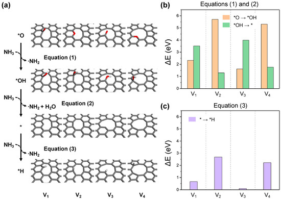
Figure 6.
(a) The optimized structures for each reaction step in the NH3 activation process. The reaction energy diagrams for equations (b) (1) and (2), and (c) (3).
The highly reactive NH2 radical, generated through the first NH3 activation process, can revert to a stable molecule as an amine or hydroxylamine by bonding with *H or *OH at the defective edges of the GO surface. This process potentially exposes dangling carbon or topological defect sites on the surface, and is referred to as the carbon activation process (Equations (4) and (5), Figure 7a). As depicted in Figure 7b, the dehydrogenation reaction (Equation (4)) is exothermic in all cases, while the removal of hydroxyl groups (Equation (5)) is exclusively exothermic in structures V2 and V4, which possess pentagonal topological defects. This specificity is due to the strong binding between dangling carbon and hydroxyl in structures V1 and V3. Nevertheless, with the endothermic reaction energies of V1 and V3 being around 1 eV, NH2 radical-induced carbon activation is anticipated to be feasible at actual thermal treatment conditions. The active carbon sites formed can either facilitate further NH3 activation or bind to other NH2 radicals, promoting the nitrogen doping of graphene in the primary amine form (Equation (6)). As shown in Figure 7c, bond formation with NH2 radicals is exothermic in all scenarios, with structures V1 and V3 exhibiting significantly higher bonding energies at dangling carbon sites compared to the topological defect sites in V2 and V4.
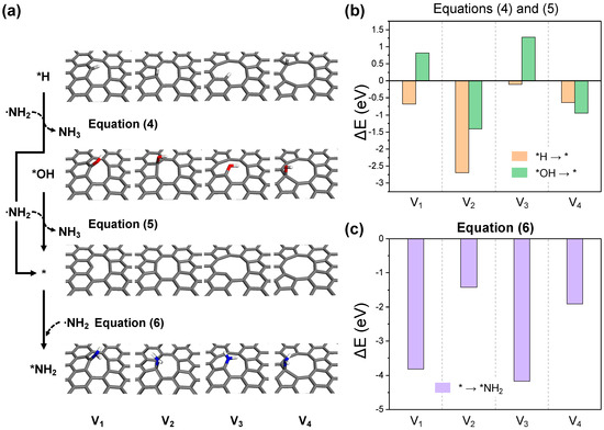
Figure 7.
(a) The optimized structures for each reaction step in the carbon activation and ·NH2 adsorption processes. The reaction energy diagrams for equations (b) (4) and (5), and (c) (6).
The subsequent step involves the embedded NH2 functional group undergoing dehydrogenation to become part of the in-plane carbon network. Among several possible dehydrogenation pathways, a representative process involves the sequential loss of hydrogen from the NH2 radical, similar to the preceding carbon activation process (Equations (7) and (8), Figure 8a). The reaction energy for this process turns out to be exothermic for all structures, as shown in Figure 8b. The largest reaction energies are observed in the formation of in-plane structures, which vary depending on the defect topology (Equation (7) for V2 and V4, Equation (8) for V1 and V3). Given a continuous supply of the dehydrogenation agent, a NH2 radical, the final structures could predominantly be graphitic and pyridinic by completing the reaction in Equation (8). However, in the absence of sufficient NH2 radicals, nearby reactive carbon sites could remove hydrogen from the adsorbed amine (Equation (9), Figure 8a). As depicted in Figure 8c, this scenario shows favorable thermodynamics only for V1 and V3, where bonding with H is easier for the surrounding carbon, but even for V2 and V4, the endothermic energy change is not significant, suggesting that the reaction could proceed with surplus thermal energy.
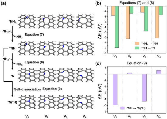
Figure 8.
(a) The optimized structures for each reaction step in the -NH2 dehydrogenation process. The reaction energy diagrams for equations (b) (7) and (8), and (c) (9).
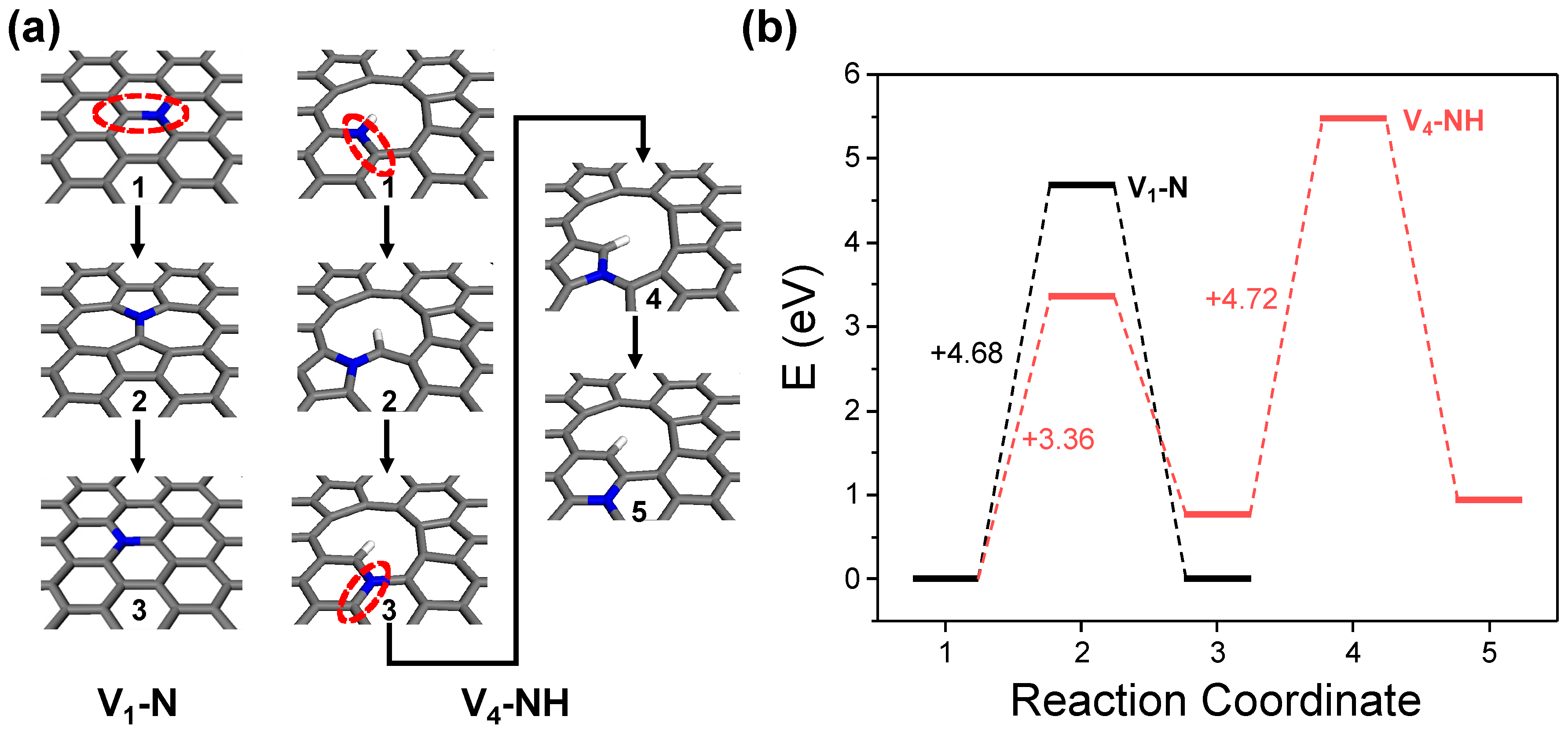
It is noteworthy that the ideal graphitic nitrogen doping site can only be formed in the V1 structure. Considering that the actual GO surface contains a variety of complex defective structures, the proportion of the ideal V1 structure is expected to be low. Consequently, the generation of graphitic nitrogen doping sites must commence with initial doping as either pyridinic or pyrrolic nitrogen at large carbon vacancies or edges, followed by the subsequent thermal energy-driven rotation and rearrangement of C–N bonds (Figure 9a). This aligns with experimental observations, wherein the proportion of graphitic nitrogen sites is generally found to be lower compared to pyridinic sites and the quantity of graphitic sites increases under more intense thermal treatment conditions [19]. As shown in Figure 9b, DFT calculations using the V4-NH model for the evolution of nitrogen doping sites reveal that initiating the first in-plane C–N bond rotation to form graphitic nitrogen from the vacancy defect requires 3.36 eV. Given the rotation energy barrier for an ideal graphitic nitrogen doping site calculated from the V1–N model is 4.68 eV, this suggests that under similar thermal treatment conditions, the configuration of nitrogen at large defects or edges can evolve more readily. However, the energy required for the second C–N bond rotation, which facilitates further migration of graphitic nitrogen into the basal plane, rises to 4.72 eV. This gradual increase in the energy barrier indicates that the location of graphitic nitrogen doping sites during NRGO synthesis is more likely to exist near vacancy defects or edges, rather than at the center of the basal plane.
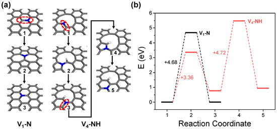
Figure 9.
Thermodynamic energy barrier analysis for nitrogen site transition of ideal graphitic nitrogen at basal plane (V1–N) and pyrrolic nitrogen at vacancy defect (V4–NH). (a) Geometries of reaction coordinates and (b) energy diagram.
3. Conclusions
To conclude, this work successfully presents atomic-scale simulations of the nitrogen doping mechanism in GO materials, focusing on the role of carbon vacancy defects using ReaxFF MD and DFT simulations. The MD results indicate that nitrogen doping in GO is predominantly initiated at vacancy defect sites, manifesting initially as primary amine functional groups. Furthermore, DFT calculations reveal the detailed reaction thermodynamics of the nitrogen doping process on systematic carbon vacancy models. This study details the activation of NH3 molecules, the formation of reactive NH2 radicals, and their adsorption and transformation on the GO surface into stable nitrogen-doped configurations. This highlights a strong correlation with the structure of vacancy defects. These findings are crucial for developing strategies to control and optimize nitrogen doping in GO, with the aim of enhancing the performance of NRGO for various applications. This comprehensive analysis uncovers the complexity of the doping mechanism and the factors influencing it, guiding future efforts to maximize doping efficiency and achieve desired nitrogen configurations in NRGO.
4. Computational Methods
4.1. ReaxFF MD Simulations
MD simulations were performed using a reactive force field [42], a bond-order dependent potential that accurately captures bond breaking and formation processes. All simulations were carried out within a canonical ensemble (NVT) utilizing a Nosé-Hoover thermostat (damping constant: 100 fs) and time steps of 0.25 fs, employing the Large-scale Atomic/Molecular Massively Parallel Simulator (LAMMPS) program [43]. Periodic boundary conditions were applied in all three directions, with a 30 Å vacuum slab along the surface normal direction. The initial GO structure, having randomly located oxygen functional groups, was heated from 10 K to 1000 K over 50 ps and subsequently annealed at 1000 K for 300 ps with 60 H2 molecules to achieve the stable formation of functional groups on GO. By-product molecules were removed after the annealing procedure. For nitrogen doping simulations, 150 NH3 molecules were introduced into a double-sized vacuum slab to ensure a sufficient number of NH3 molecules for simulating conditions rich in reactant. Each simulation model was then heated again from 10 K to 1000 K for 50 ps, followed by thermal reduction at 1000 K for 3 ns to model simultaneous oxygen reduction and nitrogen doping reactions. Trajectory analysis for the bonding states was conducted every 5 ps, with the bond criterion based on the sum of covalent radii of the two connected atoms and a tolerance factor ranging from 0.6 to 1.15.
4.2. DFT Simulations
DFT simulations were conducted using the Perdew–Burke–Ernzerhof (PBE) exchange–correlation functional [44], employing the Vienna Ab initio Simulation Package (VASP) program [45]. The interaction between electrons and ions was modeled by the projector augmented wave (PAW) method, with a plane-wave energy cutoff set at 400 eV. A rectangular graphene base cell containing 72 carbon atoms, with lattice parameters of 12.81 Å by 14.80 Å, was derived from the optimized bulk graphite structure. The Monkhorst-Pack k-point grids were set to 3 × 3 × 1. To mitigate unwanted interactions between periodic images, a 15 Å vacuum region was introduced along the surface normal direction, complemented by a dipole correction scheme. The Gaussian smearing method was utilized to determine electron occupation, featuring a smearing energy of 0.1 eV. Geometry optimizations proceeded until the forces on atoms were below 0.01 eV/Å and the total energy convergence reached a threshold of less than 10−5 eV.
Author Contributions
G.K. carried out all MD and DFT calculations and wrote this manuscript. H.K. provided computational resources and research ideas. H.-K.L. provided research ideas and wrote this manuscript. All authors have read and agreed to the published version of the manuscript.
Funding
This work is supported by the National Research Foundation of Korea, funded by the Ministry of Science and ICT (grant no. 2022R1C1C1011484 and 2022M3J1A1085384).
Data Availability Statement
The data presented in this study are available upon reasonable request.
Conflicts of Interest
The authors declare no conflicts of interest.
References
- Wang, X.; Li, X.; Zhang, L.; Yoon, Y.; Weber, P.K.; Wang, H.; Guo, J.; Dai, H. N-doping of graphene through electrothermal reactions with ammonia. Science 2009, 324, 768–771. [Google Scholar] [CrossRef] [PubMed]
- Neto, A.H.C.; Guinea, F.; Peres, N.M.R.; Novoselov, K.S.; Geim, A.K. The electronic properties of graphene. Rev. Mod. Phys. 2009, 81, 109. [Google Scholar] [CrossRef]
- Morozov, S.V.; Novoselov, K.S.; Katsnelson, M.I.; Schedin, F.; Elias, D.C.; Jaszczak, J.A.; Geim, A.K. Giant intrinsic carrier mobilities in graphene and its bilayer. Phys. Rev. Lett. 2008, 100, 016602. [Google Scholar] [CrossRef] [PubMed]
- Balandin, A.A.; Ghosh, S.; Bao, W.; Calizo, I.; Teweldebrhan, D.; Miao, F.; Lau, C.N. Superior thermal conductivity of single-layer graphene. Nano Lett. 2008, 8, 902–907. [Google Scholar] [CrossRef] [PubMed]
- Ohta, T.; Bostwick, A.; Seyller, T.; Horn, K.; Rotenberg, E. Controlling the electronic structure of bilayer graphene. Science 2006, 313, 951–954. [Google Scholar] [CrossRef]
- Zhong, Y.L.; Tian, Z.; Simon, G.P.; Li, D. Scalable production of graphene via wet chemistry: Progress and challenges. Mater. Today 2015, 18, 73–78. [Google Scholar] [CrossRef]
- Feng, Z.; Zhang, C.; Chen, J.; Wang, Y.; Jin, X.; Zhang, R.; Hu, J. An easy and eco-friendly method to prepare reduced graphene oxide with Fe(OH)2 for use as a conductive additive for LiFePO4 cathode materials. RSC Adv. 2013, 3, 4408–4415. [Google Scholar] [CrossRef]
- Sun, Z.; Hu, Y.H. Ultrafast, low-cost, and mass production of high-quality graphene. Angew. Chem. Int. Ed. 2020, 59, 9232–9234. [Google Scholar] [CrossRef] [PubMed]
- Coroş, M.; Pogăcean, F.; Roşu, M.-C.; Socaci, C.; Borodi, G.; Mageruşan, L.; Biriş, A.R.; Pruneanu, S. Simple and cost-effective synthesis of graphene by electrochemical exfoliation of graphite rods. RSC Adv. 2016, 6, 2651–2661. [Google Scholar] [CrossRef]
- Si, C.; Duan, W.; Liu, Z.; Liu, F. Electronic strengthening of graphene by charge doping. Phys. Rev. Lett. 2012, 109, 226802. [Google Scholar] [CrossRef]
- Giovannetti, G.; Khomyakov, P.A.; Brocks, G.; Karpan, V.M.; van den Brink, J.; Kelly, P.J. Doping graphene with metal contacts. Phys. Rev. Lett. 2008, 101, 026803. [Google Scholar] [CrossRef]
- Nistor, R.A.; Newns, D.M.; Martyna, G.J. The role of chemistry in graphene doping for carbon-based electronics. ACS Nano 2011, 5, 3096–3103. [Google Scholar] [CrossRef] [PubMed]
- Miao, X.; Tongay, S.; Petterson, M.K.; Berke, K.; Rinzler, A.G.; Appleton, B.R.; Hebard, A.F. High efficiency graphene solar cells by chemical doping. Nano Lett. 2012, 12, 2745–2750. [Google Scholar] [CrossRef]
- Liu, H.; Liu, Y.; Zhu, D. Chemical doping of graphene. J. Mater. Chem. 2011, 21, 3335–3345. [Google Scholar] [CrossRef]
- Wang, H.; Maiyalagan, T.; Wang, X. Review on recent progress in nitrogen-doped graphene: Synthesis, characterization, and its potential applications. ACS Catal. 2012, 2, 781–794. [Google Scholar] [CrossRef]
- Guo, B.; Liu, Q.; Chen, E.; Zhu, H.; Fang, L.; Gong, J.R. Controllable N-doping of graphene. Nano Lett. 2010, 10, 4975–4980. [Google Scholar] [CrossRef] [PubMed]
- Lin, Y.-C.; Lin, C.-Y.; Chiu, P.-W. Controllable graphene N-doping with ammonia plasma. Appl. Phys. Lett. 2010, 96, 133110. [Google Scholar] [CrossRef]
- Geng, D.; Chen, Y.; Chen, Y.; Li, Y.; Li, R.; Sun, X.; Ye, S.; Knights, S. High oxygen-reduction activity and durability of nitrogen-doped graphene. Energy Environ. Sci. 2011, 4, 760–764. [Google Scholar] [CrossRef]
- Zhang, L.-S.; Liang, X.-Q.; Song, W.-G.; Wu, Z.-Y. Identification of the nitrogen species on N-doped graphene layers and Pt/NG composite catalyst for direct methanol fuel cell. Phys. Chem. Chem. Phys. 2010, 12, 12055–12059. [Google Scholar] [CrossRef]
- Lai, L.; Potts, J.R.; Zhan, D.; Wang, L.; Poh, C.K.; Tang, C.; Gong, H.; Shen, Z.; Lin, J.; Ruoff, R.S. Exploration of the active center structure of nitrogen-doped graphene-based catalysts for oxygen reduction reaction. Energy Environ. Sci. 2012, 5, 7936–7942. [Google Scholar] [CrossRef]
- Wang, X.; Sun, G.; Routh, P.; Kim, D.-H.; Huang, W.; Chen, P. Heteroatom-doped graphene materials: Syntheses, properties and applications. Chem. Soc. Rev. 2014, 43, 7067–7098. [Google Scholar] [CrossRef] [PubMed]
- Sun, L.; Wang, L.; Tian, C.; Tan, T.; Xie, Y.; Shi, K.; Li, M.; Fu, H. Nitrogen-doped graphene with high nitrogen level via a one-step hydrothermal reaction of graphene oxide with urea for superior capacitive energy storage. RSC Adv. 2012, 2, 4498–4506. [Google Scholar] [CrossRef]
- Li, X.; Wang, H.; Robinson, J.T.; Sanchez, H.; Diankov, G.; Dai, H. Simultaneous nitrogen doping and reduction of graphene oxide. J. Am. Chem. Soc. 2009, 131, 15939–15944. [Google Scholar] [CrossRef] [PubMed]
- Sheng, Z.-H.; Shao, L.; Chen, J.-J.; Bao, W.-J.; Wang, F.-B.; Xia, X.-H. Catalyst-free synthesis of nitrogen-doped graphene via thermal annealing graphite oxide with melamine and its excellent electrocatalysis. ACS Nano 2011, 5, 4350–4358. [Google Scholar] [CrossRef] [PubMed]
- Zhang, Y.; Ge, J.; Wang, L.; Wang, D.; Ding, F.; Tao, X.; Chen, W. Manageable N-doped graphene for high performance oxygen reduction reaction. Sci. Rep. 2013, 3, 2771. [Google Scholar] [CrossRef] [PubMed]
- Mou, Z.; Chen, X.; Du, Y.; Wang, X.; Yang, P.; Wang, S. Forming mechanism of nitrogen doped graphene prepared by thermal solid-state reaction of graphite oxide and urea. Appl. Surf. Sci. 2011, 258, 1704–1710. [Google Scholar] [CrossRef]
- Luo, Z.; Lim, S.; Tian, Z.; Shang, J.; Lai, L.; MacDonald, B.; Fu, C.; Shen, Z.; Yu, T.; Lin, J. Pyridinic N doped graphene: Synthesis, electronic structure, and electrocatalytic property. J. Mater. Chem. 2011, 21, 8038–8044. [Google Scholar] [CrossRef]
- Kong, X.-K.; Chen, Q.-W. Improved performance of graphene doped with pyridinic N for Li-ion battery: A density functional theory model. Phys. Chem. Chem. Phys. 2013, 15, 12982–12987. [Google Scholar] [CrossRef]
- Mondal, T.; Bhowmick, A.K.; Krishnamoorti, R. Controlled synthesis of nitrogen-doped graphene from a heteroatom polymer and its mechanism of formation. Chem. Mater. 2015, 27, 716–725. [Google Scholar] [CrossRef]
- Bagri, A.; Mattevi, C.; Acik, M.; Chabal, Y.J.; Chhowalla, M.; Shenoy, V.B. Structural evolution during the reduction of chemically derived graphene oxide. Nat. Chem. 2010, 2, 581–587. [Google Scholar] [CrossRef]
- Wilson, N.R.; Pandey, P.A.; Beanland, R.; Young, R.J.; Kinloch, I.A.; Gong, L.; Liu, Z.; Suenaga, K.; Rourke, J.P.; York, S.J.; et al. Graphene Oxide: Structural Analysis and Application as a Highly Transparent Support for Electron Microscopy. ACS Nano 2009, 3, 2547–2556. [Google Scholar] [CrossRef] [PubMed]
- Kwak, D.; Khetan, A.; Noh, S.; Pitsch, H.; Han, B. First Principles Study of Morphology, Doping Level, and Water Solvation Effects on the Catalytic Mechanism of Nitrogen-Doped Graphene in the Oxygen Reduction Reaction. ChemCatChem 2014, 6, 2662–2670. [Google Scholar] [CrossRef]
- Telychko, M.; Mutombo, P.; Ondráček, M.; Hapala, P.; Bocquet, F.C.; Kolorenč, J.; Vondráček, M.; Jelínek, P.; Švec, M. Achieving high-quality single-atom nitrogen doping of graphene/SiC(0001) by ion implantation and subsequent thermal stabilization. ACS Nano 2014, 8, 7318–7324. [Google Scholar] [CrossRef] [PubMed]
- Chen, Y.; Xie, B.; Ren, Y.; Yu, M.; Qu, Y.; Xie, T.; Zhang, Y.; Wu, Y. Designed nitrogen doping of few-layer graphene functionalized by selective oxygenic groups. Nanoscale Res. Lett. 2014, 9, 646. [Google Scholar] [CrossRef]
- Huang, S.-F.; Terakura, K.; Ozaki, T.; Ikeda, T.; Boero, M.; Oshima, M.; Ozaki, J.-I.; Miyata, S. First-principles calculation of the electronic properties of graphene clusters doped with nitrogen and boron: Analysis of catalytic activity for the oxygen reduction reaction. Phys. Rev. B 2009, 80, 235410. [Google Scholar] [CrossRef]
- Park, S.; Hu, Y.; Hwang, J.O.; Lee, E.-S.; Casabianca, L.B.; Cai, W.; Potts, J.R.; Ha, H.-W.; Chen, S.; Oh, J.; et al. Chemical structures of hydrazine-treated graphene oxide and generation of aromatic nitrogen doping. Nat. Commun. 2012, 3, 638. [Google Scholar] [CrossRef] [PubMed]
- Das, P.; Ibrahim, S.; Chakraborty, K.; Ghosh, S.; Pal, T. Stepwise reduction of graphene oxide and studies on defect-controlled physical properties. Sci. Rep. 2024, 14, 294. [Google Scholar] [CrossRef]
- Wang, W.-W.; Dang, J.-S.; Zhao, X.; Nagase, S. Formation mechanisms of graphitic-N: Oxygen reduction and nitrogen doping of graphene oxides. J. Phys. Chem. C 2016, 120, 5673–5681. [Google Scholar] [CrossRef]
- Li, X.-F.; Lian, K.-Y.; Liu, L.; Wu, Y.; Qiu, Q.; Jiang, J.; Deng, M.; Luo, Y. Unraveling the formation mechanism of graphitic nitrogen-doping in thermally treated graphene with ammonia. Sci. Rep. 2016, 6, 23495. [Google Scholar] [CrossRef]
- Hou, D.; Yang, T.; Tang, J.; Li, S. Reactive force-field molecular dynamics study on graphene oxide reinforced cement composite: Functional group de-protonation, interfacial bonding and strengthening mechanism. Phys. Chem. Chem. Phys. 2018, 20, 8773–8789. [Google Scholar] [CrossRef]
- Bawari, S.; Nair, M.N.; Mondal, J.; Narayanan, T.N. Elucidating the Mechanism of Nitrogen Doping in Graphene Oxide: Structural Evolution of Dopants and the Role of Oxygen. J. Phys. Chem. C 2021, 125, 22547–22553. [Google Scholar] [CrossRef]
- Duin, A.C.T.; Dasgupta, S.; Lorant, F.; Goddard, W.A. ReaxFF: A Reactive Force Field for Hydrocarbons. J. Phys. Chem. A 2001, 105, 9396–9409. [Google Scholar] [CrossRef]
- Thompson, A.P.; Aktulga, H.M.; Berger, R.; Bolintineanu, D.S.; Brown, W.M.; Crozier, P.S.; Veld, P.J.; Kohlmeyer, A.; Moore, S.G.; Nguyen, T.D.; et al. LAMMPS—A flexible simulation tool for particle-based materials modeling at the atomic, meso, and continuum scales. Comp. Phys. Comm. 2022, 271, 108171. [Google Scholar] [CrossRef]
- Perdew, J.P.; Burke, K.; Ernzerhof, M. Generalized Gradient Approximation Made Simple. Phys. Rev. Lett. 1997, 78, 1396. [Google Scholar] [CrossRef]
- Kresse, G.; Furthmüller, J. Efficiency of ab-initio total energy calculations for metals and semiconductors using a plane-wave basis set. Comput. Mat. Sci. 1996, 6, 15–50. [Google Scholar] [CrossRef]


Disclaimer/Publisher’s Note: The statements, opinions and data contained in all publications are solely those of the individual author(s) and contributor(s) and not of MDPI and/or the editor(s). MDPI and/or the editor(s) disclaim responsibility for any injury to people or property resulting from any ideas, methods, instructions or products referred to in the content. |
© 2024 by the authors. Licensee MDPI, Basel, Switzerland. This article is an open access article distributed under the terms and conditions of the Creative Commons Attribution (CC BY) license (https://creativecommons.org/licenses/by/4.0/).