Article

Rational Design of Z-Scheme Heterostructures Composed of Bi/Fe-Based MOFs for the Efficient Photocatalytic Degradation of Organic Pollutants

School of Physics and Electronic Engineering, Jiangsu University, Zhenjiang 212013, China
*
Author to whom correspondence should be addressed.
Catalysts 2024, 14(6), 356; https://doi.org/10.3390/catal14060356
Submission received: 29 April 2024 / Revised: 24 May 2024 / Accepted: 29 May 2024 / Published: 30 May 2024
(This article belongs to the Section Photocatalysis)

Abstract

:
Metal–organic frameworks (MOFs) have recently gained attention as a highly promising category of photocatalytic materials, showing great potential in the degradation of organic dyes such as Rhodamine B (RhB). Nonetheless, the mono-metal MOF materials in this application are often constrained by their limited light absorption capabilities and their propensity for recombination with carriers. The combination of different metal-based MOFs to form heterogeneous reactors could present a promising approach for the removal of dyes from water. In this work, a new CAU-17/MIL-100(Fe) Z-scheme heterojunction photocatalyst composed of two MOFs with the same ligands is reported to realize the efficient degradation of dyes in water. The combination of the two MOFs results in a significant enhancement of the surface open sites, optical responsivity range, and charge-separating efficiency through synergistic effects. In addition, the capture experiments conducted on the photocatalytic process have verified that ∙O2 and h+ are the primary active species. Consequently, CAU-17/MIL-100(Fe) exhibited excellent photocatalytic activity and stability. The degradation rate of the optimal CAU-17/MIL-100(Fe) photocatalyst was 34.55 times that of CAU-17 and 3.60 times that of MIL-100(Fe). Our work provides a new strategy for exploring the visible-light degradation of RhB in bimetallic MOF composites.

1. Introduction

The proliferation of organic pollutants emanating from diverse industrial sectors, including the textile, plastic, leather, and paper-making industries, poses a significant and globally pervasive challenge to the ecology and to human health [1,2]. Conventional methods for contaminant treatment, including membrane adsorption or ion exchange have the disadvantages of expensive cost and secondary pollution, which limits their applications in modern manufacturing. Therefore, developing green and effective technology is urgently required [3,4]. In recent years, there has been a considerable increase in interest in photocatalytic technology due to its cost-effectiveness and simple operation for pollutant degradation [5,6,7]. Within the domain of photocatalytic technology, the pivotal challenge lies in the design and synthesis of photocatalysts that exhibit enhanced redox potential, a broad spectral response, and superior efficiency in the separation of electron–hole pairs. These attributes are paramount in augmenting the rate of pollutant degradation, thereby offering a promising avenue for the advancement of sustainable and effective pollutant remediation strategies. To enhance the degradation rate of pollutants in photocatalytic technology, it is crucial to focus on optimizing the redox capacity, response range, and electron–hole pair separation efficiency of photocatalysts [8,9,10].
Metal–organic frameworks (MOFs) have garnered significant interest among researchers in the energy and environmental sectors due to their distinctive characteristics, like their versatile coordination structure and exceptional surface area [11]. Bismuth (Bi), as a classical kind of main-group metal, features outstanding advantages, including high abundance, strong stability, environmental friendliness, and flexible coordination relations, which is conductive to the production of diversified MOF materials [12,13]. CAU-17, a type of MOF containing bismuth, possesses hexagonal, rectangular, and triangular channels that facilitate the passage and adsorption of pollutants [14]. The remarkable ability to adsorb pollutants, combined with its semiconductor properties, renders CAU-17 a highly promising photocatalyst [15]. However, the current photocatalytic performance of CAU-17 remains unsatisfactory due to its limited efficiency in charge separation and use of visible light.
There has been significant interest in creating heterostructure materials through the integration of MOF with other functionalized substances to enhance the photocatalytic efficiency of MOF [16,17]. Even though the MOF semiconductor successfully combines adsorption and enhances the carrier-separation efficiency, important issues still remain, including (i) the weak interaction between the semiconductor and MOF [18] and (ii) the secondary pollution caused by semiconductors [19]. Therefore, further optimization is needed. The catalytic potential of MIL-100(Fe) in pollutant degradation has been the subject of much research due to its narrow band gap [20,21]. Due to the similarity of ligands between CAU-17 and MIL-100(Fe), it is possible for different MOF materials to combine with each other to construct heterojunctions. However, constructing CAU-17 with MIL-100(Fe) for efficient photocatalytic pollutant degradation has not yet been reported.
In this work, the CAU-17/MIL-100(Fe) Z-scheme heterojunction photocatalysts were successfully prepared through the in situ growth of MIL-100(Fe) on rod-like CAU-17. This unique architecture maximizes the availability of active sites for both adsorption and photocatalytic reactions within the MOF. In comparison with the individual CAU-17 and MIL-100(Fe), the combined CAU-17/MIL-100(Fe) demonstrated a remarkable improvement in the degradation efficiency of RhB under visible-light irradiation. Mechanistic studies revealed that the enhanced photocatalytic ability of CAU-17/MIL-100(Fe) is derived from the efficient carrier separation and migration and enhanced light absorption. This work demonstrates the acceleration of the reaction kinetics of RhB degradation, opening a new approach for the design of novel photocatalysts.

2. Results and Discussion

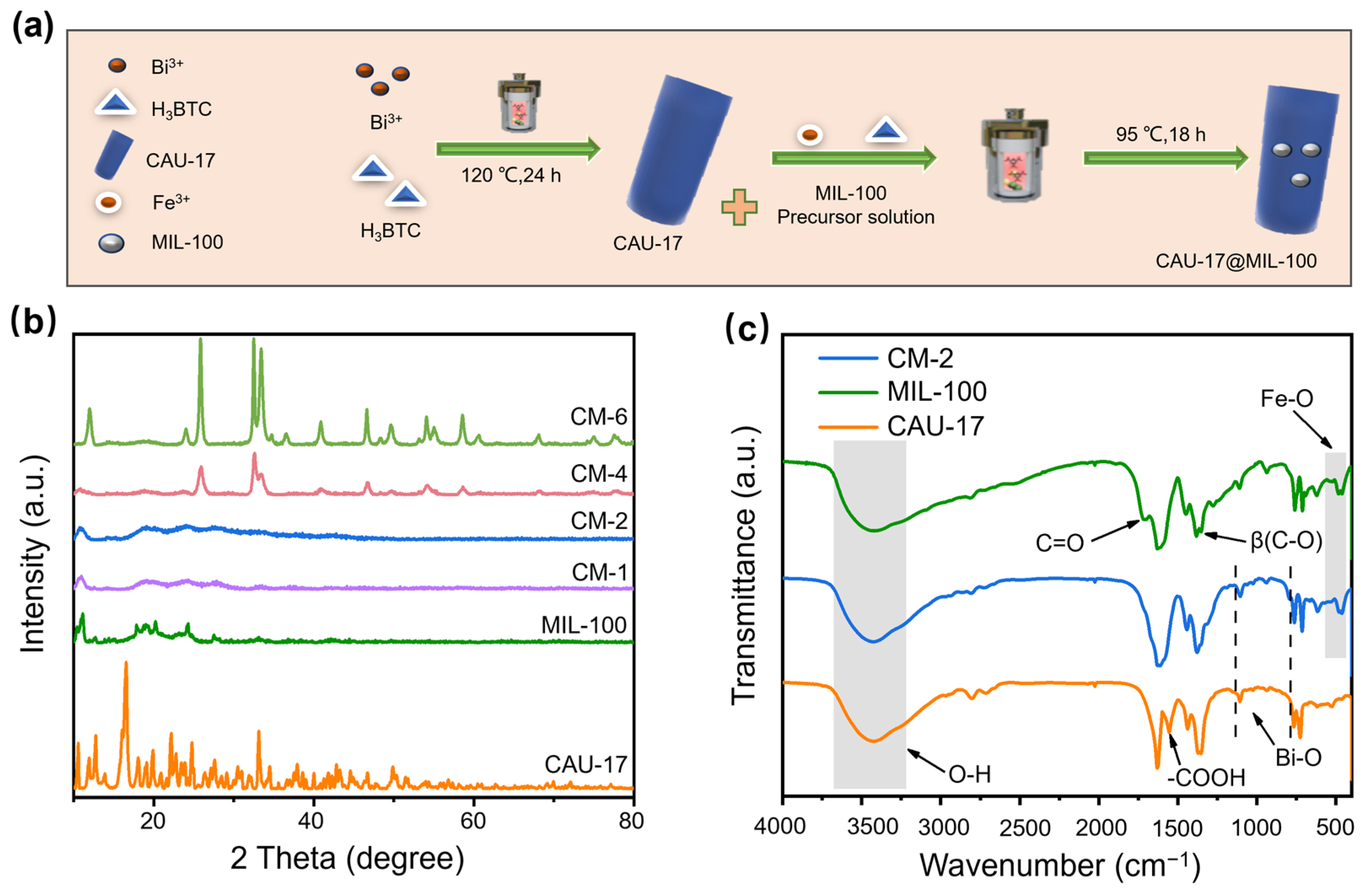
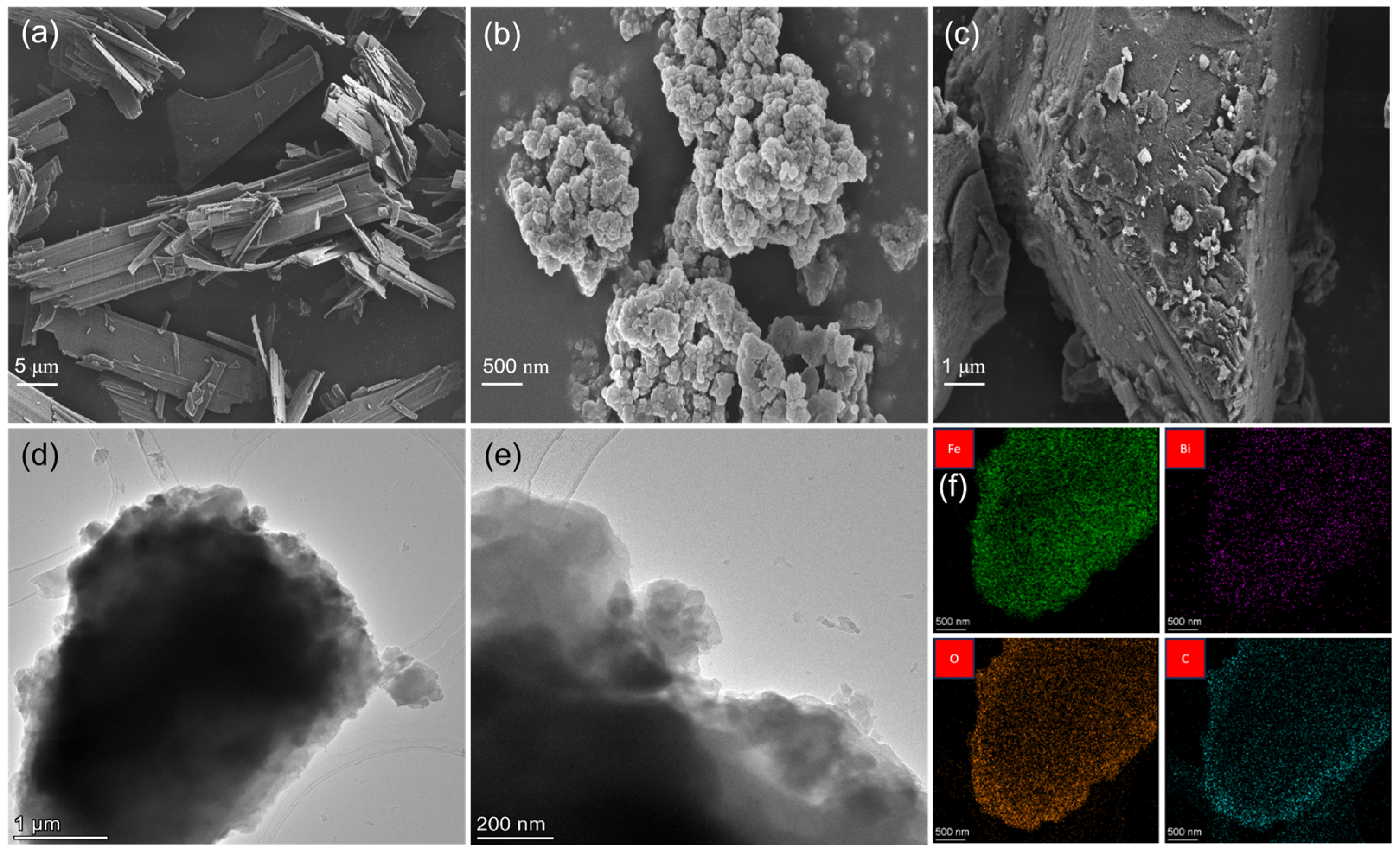
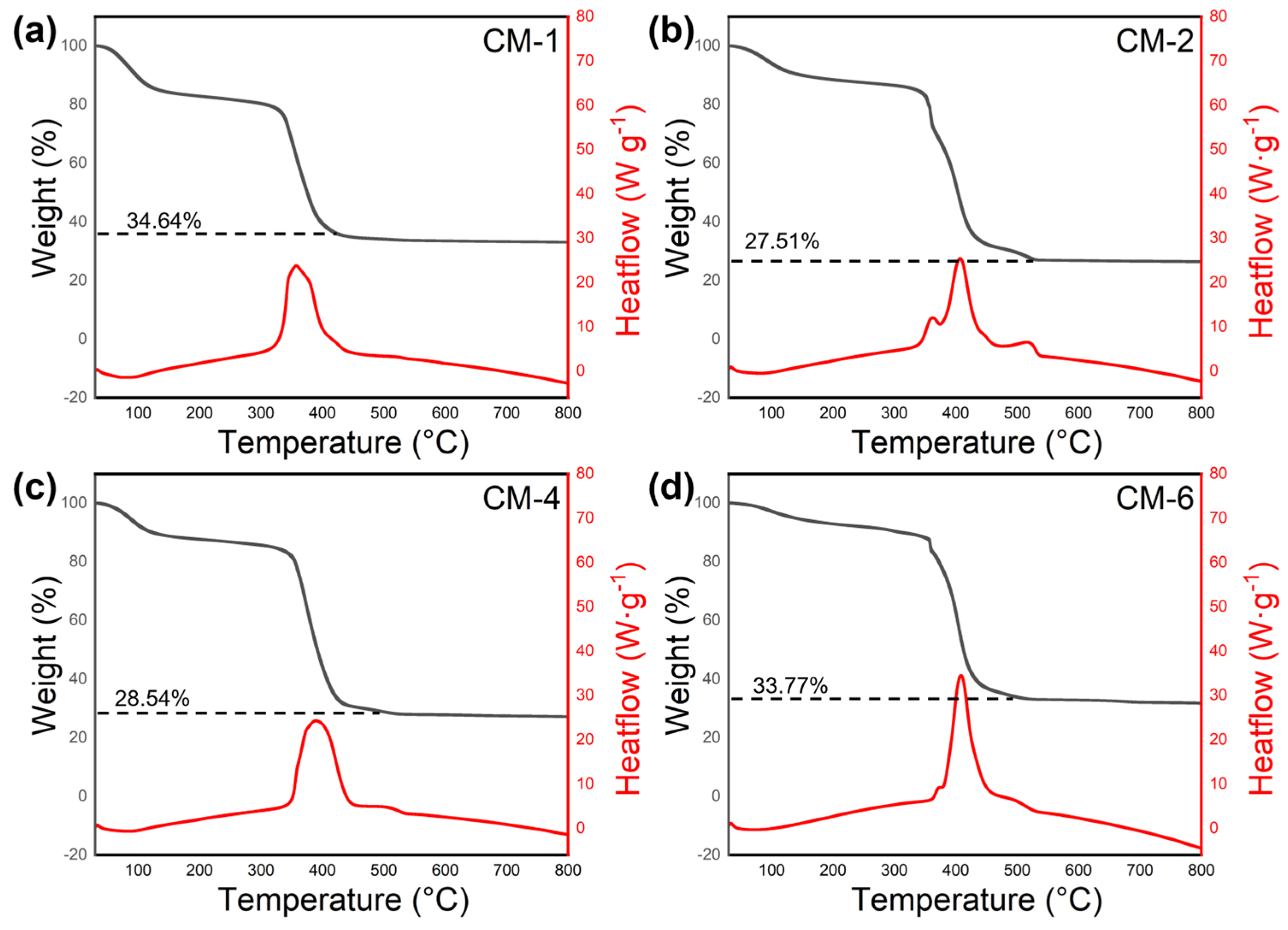
2.1. Characterization of Structure and Morphology

According to the depicted procedure in Figure 1a, various specimens comprising CAU-17, MIL-100(Fe), and composites of CAU-17/MIL-100(Fe) were provided. The XRD analysis was conducted on the prepared photocatalysts, and the findings are presented in Figure 1b. It is evident that the intense diffraction peaks observed at 19.1° and 24.0° for the synthesized CAU-17 match those reported in previous studies, revealing the achievement of CAU-17 synthesis [22,23]. The dominant peak observed at an angle of 10.77° corresponds to MIL-100(Fe), which exhibits a consistent peak position in CM-n (n = 1, 2, 4, 6) similar to that in CAU-17 and MIL-100(Fe) [24]. This indicates that MIL-100(Fe) was synthesized on CAU-17.
The formation of CAU-17, MIL-100(Fe) and CM-2 was further confirmed by FT-IR spectra (Figure 1c). It can be observed that asymmetric vibration of C-O bonds, carboxyl groups, and carbonyl groups appeared at 1363, 1552, and 1721 cm−1 in each material, respectively [25,26]. The peaks of the three samples at 3250–3550 cm−1 correspond to the vibration of O-H bonds in chemisorbed H2O [27]. The presence of O-Bi-O bands at 400–800 cm−1 is indicative of characteristic peaks in CAU-17 [28]. MIL-100(Fe) possesses characteristic peaks of Fe-O bands at approximately 472 cm−1 [29]. CM-2 possesses the above two characteristic peaks, which indicates its successful synthesis.
The morphologies of the CAU-17, MIL-100(Fe), and CM-2 catalysts were examined using SEM. As observed, the length of CAU-17 is 10 μm, and it exhibits a characteristic columnar structure (Figure 2a). Figure 2b shows the topography of MIL-100(Fe), and it can be seen that nano-sized particles are aggregated. As illustrated in Figure 2c, MIL-100(Fe) nanoparticles were dispersed on the surface of CAU-17, while the cylindrical CAU-17 was clearly coated by a substantial quantity of MIL-100(Fe). The detailed morphology of CM-2 was further analyzed by TEM. As shown in Figure 2d,e, MIL-100(Fe) nanoparticles were closely attached to the surface of CAU-17. This interaction between the cylindrical structure of CAU-17 and the nanoparticles of MIL-100(Fe) is a result of an electrostatic self-assembling process triggered by positively charged entities on the surface of CAU-17 and negatively charged entities on the surface of MIL-100(Fe) when they are present in a solution. The electrostatic interaction between CAU-17 and MIL-100(Fe) leads to an increase in the contact area between the final photocatalyst components and promotes the electron–hole conversion between CAU-17 and MIL-100(Fe). Figure 2f presented the elemental mappings of the CM-2 composite material, revealing the uniform presence of Fe, Bi, C, and O elements. This observation suggests that the material exhibits excellent homogeneity.
The N2 adsorption isotherms and plots illustrating the distribution of pore sizes can be observed in Figure 3. The N2 adsorption–desorption isotherm of MIL-100(Fe) shows a curve that falls between type IV and I, indicating the presence of both mesoporous and microporous materials. Meanwhile, the MIL-100(Fe) surface area SBET = 80.7499 m2 g−1 (Figure 3a). The N2 isothermal adsorption–desorption curve for CAU-17 shows a curve of type I, indicating the presence of microporous materials. The SBET of CAU-17 is 13.6113 m2 g−1 (Figure 3b). Based on the data presented in Figure 3c, it can be observed that CM-2 exhibits type IV isotherms accompanied by an H3 hysteresis loop, suggesting the presence of mesoporous structures. The SBET of CM-2 composite is 77.3923 m2 g−1 (Figure 3c). The above results show that the introduction of CAU-17 to MIL-100(Fe) can maintain the large specific surface area and pore size of MIL-100(Fe). It is well known that the large surface area in the structure of photocatalysts can provide many more photoactive sites and reaction spaces, thus improving the photocatalytic performance of catalysts [30]. Therefore, it is reasonable to believe that CM-2 has a high performance of photocatalytic degradation of dyes.
To obtain the actual Bi/Fe ratios in CM-1, CM-2, CM-4, and CM-6, ICP and TGA experiments were carried out. In the ICP test result (Table 1), the Bi content of CM-1, CM2, CM-4, and CM-6 was 6.92%, 7.14%, 8.96%, and 15.96% respectively, and their Fe content was 19.25%, 14.66%, 13.66%, and 11.09% respectively. The Bi/Fe ratios of these samples were 0.36, 0.49, 0.66, and 1.44 respectively. With the increase in the proportion of Bi in the reaction substrate, the proportion of Bi in the product gradually increased. To further validate the results of the ICP test, we performed the TGA test (Figure 4). Below 100 °C, the weight loss mainly comes from water. The weight loss between 350–450 °C is caused by the oxidation of ligands, where an upward peak appears in the DSC curve that indicates the exothermic process of oxidation. Above 450 °C, Bi and Fe begin to oxidize, and the final product remaining is a mixture of oxides of Bi and Fe at 800 °C. The mass ratio of the mixture was 34.58%, 28.49%, 29.22%, and 33.76%, respectively, which is consistent with the result of ICP test.
To investigate the surface chemical characteristics of CAU-17/MIL-100(Fe) composites and to examine the interfacial interactions between CAU-17 and MIL-100(Fe), XPS analysis was conducted [31]. As depicted in Figure 5a, the analysis of CM-2 revealed the presence of only Bi, Fe, C, and O elements, providing evidence of the effective synthesis of CAU-17/MIL-100(Fe) composites. In the Bi 4f spectra (Figure 5b), the observed peaks at 159.70 and 164.99 eV correspond to Bi 4f7/2 and Bi 4f5/2, indicating that the oxidation state of bismuth is +3. In contrast, a slight shift to 159.35 and 164.61 eV is observed for the signal peaks of Bi 4f7/2 and Bi 4f5/2 in CM-2 [32]. In the spectrum of Fe 2p (Figure 5c), MIL-100(Fe) exhibited two distinct peaks at energy levels of 724.59 and 711.72 eV, corresponding to Fe 2p1/2 and Fe 2p3/2, respectively [33]. By comparison, the binding energies of Fe 2p1/2 and Fe 2p3/2 in CM-2 showed a slightly negative shift to 725.05 and 711.85 eV. For the C 1s spectrum (Figure 5d), two peaks were observed in CM-2 at energy levels of 284.8 and 288.66 eV, corresponding to the presence of C=C and C=O functional groups in H3BTC [34]. For the O 1s spectrum (Figure 5e), the peak at 531.38 eV in CAU-17 corresponds to the Bi-O bond, and the peak at 533.08eV corresponds to the Bi=O bond. The peak at 531.88 eV in MIL-100(Fe) corresponds to O-H in the adsorbed water on the sample surface, and the peak at 533.58 eV corresponds to the C=O bond [35]. In sample CM-2, the above peaks still exist, indicating that CM-2 is synthesized from CAU-17 and MIL-100(Fe). The XPS results were in agreement with the FT-IR results, providing additional evidence of the successful synthesis of the composite catalyst comprising the Bi/Fe-based MOF.

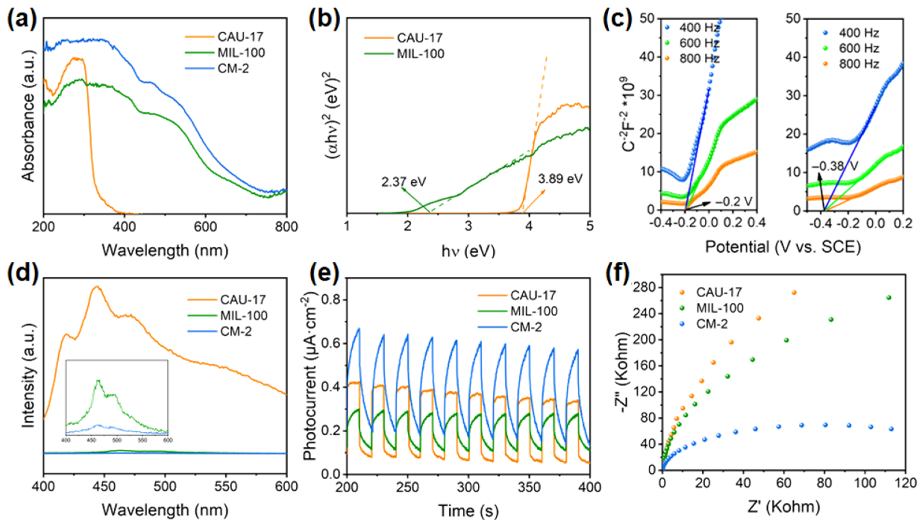
2.2. Optical and Electrochemical Properties of Photocatalysts

The UV-vis DRS technique was employed to assess the optical performance of the photocatalyst that was prepared (Figure 6a). The light-absorption capability of CAU-17 is limited to ultraviolet light, whereas MIL-100(Fe) can absorb both visible and ultraviolet light. It should be noted that the CM-2 composite material exhibits a higher level of light absorption compared with CAU-17 and MIL-100(Fe). These findings suggest that incorporating CAU-17 into MIL-100(Fe) enhances its ability to absorb light, primarily due to the stronger absorption of ultraviolet light by CAU-17. The enhanced light-absorption capability of the composite material CAU-17/MIL-100(Fe) implies a greater likelihood of being stimulated by incoming light, leading to an increased production of electrons (e) and holes (h+). This advantageous characteristic contributes to the enhancement of photocatalytic efficiency. The Kubelka–Munk Equation (1) was utilized to estimate the band-gap energy of CAU-17 and MIL-100(Fe).
α h ν = A h ν E g n / 2
The constants A, α, , and Eg represent the proportionality constant, the absorption coefficient, the photon energy, and the band gap [36]. The constant n represents the specific type of semiconductor transition. In the case of MIL-100(Fe), a direct-transition semiconductor, n has a value of 1. Conversely, for CAU-17, an indirect transition semiconductor, n is equal to 4. As shown in Figure 6b, the energy gaps (Eg) of CAU-17 and MIL-100(Fe) were determined to be 3.89 eV and 2.37 eV. The effective carrier conduction between CAU-17 and MIL-100(Fe) was further verified by Mott–Schottky measurements of CAU-17 and MIL-100(Fe). In Figure 6c, the slopes of the Mott-Schottky curves for the CAU-17 and MIL-100(Fe) samples are positive, indicating that they are n-type semiconductors. Based on the Mott–Schottky plot, the flat-band (Efb) potentials of CAU-17 and MIL-100(Fe) were calculated to be −0.2 and −0.38 eV versus SCE, which can be converted to −0.34 and −0.52 eV versus NHE [37]. Combining these values with the Eg evaluated by the Tauc plots, the valence band potentials (EVB) of CAU-17 and MIL-100(Fe) were estimated to be +3.55 and +1.85 eV vs. NHE by using Equation (2).
E V B = E C B + E g
To explore the ability of photoinduced carriers to separate, we conducted an analysis on the electrochemical impedance spectroscopy (EIS), photocurrent performance, and photoluminescence (PL) spectra of CAU-17, MIL-100(Fe), and CM-2 in their pure forms. As shown in Figure 6d, the photoluminescence (PL) spectra of all samples are observed. In comparison to pure MIL-100(Fe) and CAU-17, the prepared CM-2 exhibits a reduced PL emission intensity. This suggests that the heterojunction between CAU-17 and MIL-100(Fe) facilitates the suppression of recombination between photogenerated holes and electrons.
According to the outcomes mentioned above, CM-2 exhibits the least intensity of PL emission, indicating its remarkable capability to effectively segregate photogenerated carriers [38]. As depicted in Figure 6e, a comparison was made between the transient photocurrent response of CAU-17 without impurities, MIL-100(Fe), and CM-2. It can be observed that CM-2 exhibits a significantly higher photocurrent intensity than pure CAU-17 and MIL-100(Fe) when exposed to visible light. This indicates an improved capacity for separating photogenerated holes and electrons as well as enhanced transfer efficiency [39]. In addition, a decrease in the EIS spectra radius generally corresponds to an increase in the ability to separate e and h+. Figure 6f illustrates that different materials exhibit varying EIS radii, suggesting differences in charge-transfer resistance within the materials. The introduction of MIL-100(Fe) into CAU-17 significantly influences its charge-transfer resistance. By optimizing the amount of MIL-100(Fe) used, it is possible to reduce the charge-transfer resistance of the materials, enhance the e and h+ separation capabilities, and ultimately improve the photocatalytic efficiency [40].

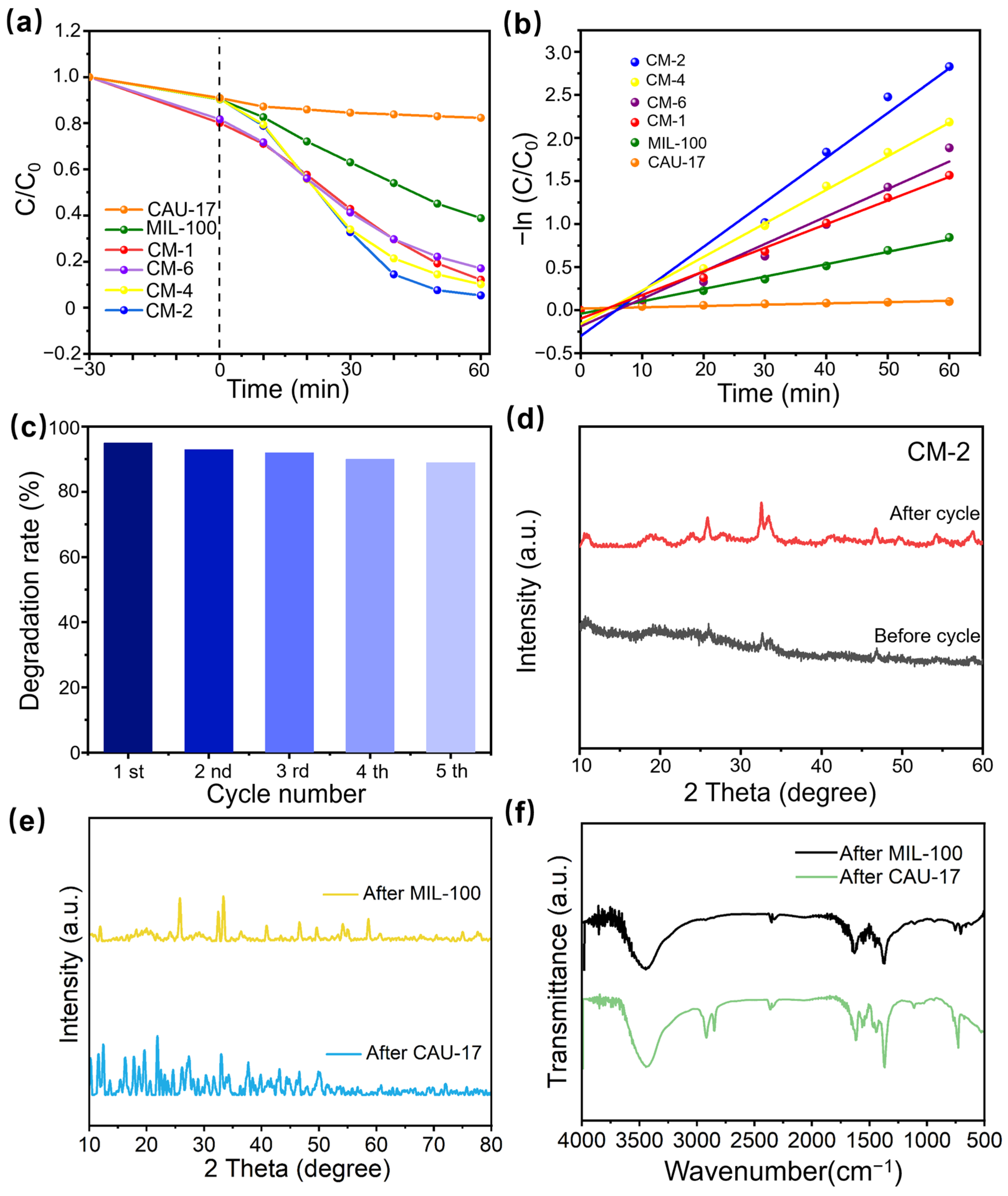
2.3. Degradation Performance

The photocatalytic performance of different samples in the decomposition of RhB under visible-light irradiation was investigated, as depicted in Figure 7. All the Fe/Bi-MOF composites exhibited superior photocatalytic performances compared with pure CAU-17 or pure MIL-100(Fe). As shown in Figure 7a, after a 60 min irradiation period, CM-1, CM-2, CM-4, and CM-6 achieved respective rates of RhB photocatalytic degradation of approximately 85%, 95%, 90%, and 90%. It is evident that among all the samples, the degradation rate of the CM-2 sample is the highest. Hence, a Bi/Fe ratio of 2:1 is considered optimal. In general, the typical photocatalytic degradation process mainly includes light absorption, the separation of photogenerated carriers, and the formation of free radicals to disrupt the molecular structure of pollutants. These factors collectively determine the ultimate elimination of pollutants. The aforementioned characterization and testing demonstrate that CM-2 exhibits a broader range of light absorption, higher light-absorption efficiency, and superior carrier separation efficiency, indicating satisfactory efficacy in pollutant degradation. Within the composite sample, an optimal proportion of Fe ions and Bi ions manifests excellent degradation performance. This is attributed to the fact that when Fe ions are too small, it is difficult to effectively attach them to the surface of CAU-17 in the hydrothermal synthesis experiment and form heterojunctions. When there are too many Fe ions, the surface of CAU-17 is inlaid with excessive MIL-100(Fe) nanoparticles, which covers the active site of photogenerated carriers and increases the recombination rate of photogenerated carriers. Figure 7b presents a quantitative assessment of the degradation kinetics of different samples using photocatalysis. The obtained results demonstrate conformity with the pseudo-first-order kinetic diagram, as indicated by Equation (3).
ln ( C / C 0 ) = k t
In the given context, k denotes the constant determining the rate of reaction, C represents the concentration of RhB under visible-light exposure, and C0 signifies the initial concentration. Based on the provided diagram, it can be observed that the CM-2 composite exhibits a superior kinetic reaction constant, indicating its remarkable photocatalytic activity performance. The degradation rate of CM-2 was 34.55 times that of CAU-17 and 3.60 times that of MIL-100(Fe). While CM-2 may not possess the highest specific surface area among all the samples, its exceptional photocatalytic performance suggests that factors such as the structure, particularly the heterojunction structure, could play a more significant role in influencing photocatalytic activity rather than solely relying on the surface area of the photocatalyst.

2.4. Stability and Reusability of Photocatalysts

Whether the catalyst can maintain stability for a long time is an important sign in measuring the quality of the catalyst. The optimal CM-2 catalyst (10 mg) and RhB solution were selected for continuous cyclic reaction tests. After each reaction, the catalyst was washed in distilled water and dried for the reaction. The activity of the catalyst remained basically unchanged after five repetitions (Figure 7c). The reduced performance may be caused by the loss of catalyst content during each washing. The XRD spectra revealed that the phase structure of CM-2 composite was preserved after photocatalytic cycles, which further proved the excellent stability of the CM-2 catalyst (Figure 7d).
Furthermore, the used CAU-17 and MIL-100(Fe) were tested by XRD (Figure 7e) and FT-IR (Figure 7f) analysis to explore their stability. Compared with fresh samples, no new peaks were generated in the XRD pattern of used MIL-100(Fe) and CAU-17, indicating that the structure of samples did not change, which indicates that the fresh samples have good stability. The FT-IR test of the samples also showed the same results.

2.5. Degradation Mechanism

In order to further explore the degradation mechanism of CM composites, the following tests were conducted. Electron spin resonance (ESR) spectroscopy was used to test ∙O2 and ∙OH free radicals, as shown in Figure 8b,c [41,42]. The results confirmed that CM can produce ∙O2 and ∙OH free radicals under light exposure. Then, the trapping agents EDTA-Na, BQ, and IPA were added to the test sample to capture h+, ∙O2, and ∙OH, respectively. The addition of BQ and EDTA to the CM-2 catalyst can significantly reduce the catalytic activity. These results indicated that the ∙O2 and h+, rather than ∙OH, played a key role in the degradation reaction (Figure 8a) [43]. We also performed an ESR test on MIL-100(Fe) and CAU-17 (Figure S1), which showed that ∙O2 and ∙OH can be generated by both CAU-17 and MIL-100(Fe) under light conditions. The intensities of peaks increased with visible-light exposure time from 5 to 10 min, verifying the generation of ∙O2 and ∙OH active substances during the photocatalytic degradation process.
Based on the characterization studies, the photocatalytic mechanism of the CAU-17/MIL-100(Fe) composite is discussed in Figure 8d. The EVB of CAU-17 and MIL-100(Fe) were determined to be +3.55 eV and +1.85 eV, while the ECB of CAU-17 and MIL-100(Fe) were −0.34 eV and −0.52 eV, respectively. The calculated results show that the conduction band of MIL-100(Fe) is lower than that of CAU-17, and the VB potential of CAU-17 is higher than that of MIL-100(Fe). In general, a semiconductor immediately produces photogenerated electrons and hole pairs after absorbing photons. According to the calculation of the band structure, type II and type Z heterojunctions can be formed between CAU-17 and MIL-100(Fe). Due to the lack of redox capacity of the type II heterojunction, the electron flow is contrary to the XPS test results, hence a Z-type heterojunction is formed between the CM composites prepared by us. When MIL-100(Fe) is in contact with CAU-17, electrons from MIL-100(Fe) will spontaneously transfer to CAU-17, resulting in the formation of an internal electric field between MIL-100(Fe) and CAU-17, with the direction of the electric field directed from MIL-100(Fe) to CAU-17. When the light is irradiated, the electrons in the MIL-100(Fe) and CAU-17 valence bands will transition to the conduction band, and the electrons in the CAU-17 conduction band will recombine with the holes in the MIL-100(Fe) band under the action of the internal electric field. Finally, O2 accepts electrons on the MIL-100(Fe) band to form a hole in the ∙O2 valence band. The CAU-17 band transforms H2O into ∙OH. The resulting ∙O2 and ∙OH degrade RhB. The reaction process can be described by the following formulas:
C A U 17 / M I L 100 + h ν e + h +
M I L 100 ( e ) + O 2 O 2
C A U 17 ( h + ) + H 2 O O H
h + / O 2 / O H + R h B p r o d u c t s + C O 2 + H 2 O

3. Materials and Methods

3.1. Chemicals

1,3,5-benzenetricarboxylic acid (H3BTC), bismuth nitrate pentahydrate (Bi(NO3)3∙5H2O), N-dimethylformamide (DMF), methanol anhydrous (MeOH), ferric trichloride hexahydrate (FeCl3∙6H2O), and Rhodamine B (RhB) were all samples that have not been treated. All the Chemicals above were obtained from Aladdin (Shanghai, China). These reagents were used without any treatment.

3.2. Synthesis of CAU-17

CAU-17 was obtained by the hydrothermal method as mentioned in the literature [44]. At ambient temperature, Bi(NO3)3∙5H2O (1 mmol) and H3BTC (3 mmol) are dissolved in 5 mL of DMF and 55 mL of anhydrous methanol. After stirring at ambient temperature for half an hour, the mixture is moved to a 100 mL autoclave lined with PTFE and subjected to heating at 120 °C for a duration of 24 h. The product is subjected to repeated washing with DMF and methanol, followed by drying at 70 °C.

3.3. Synthesis of CAU-17/MIL-100(Fe)

CAU-17/MIL-100(Fe) catalysts were obtained by the hydrothermal method. The H3BTC compound was dissolved in 30 mL of DMF and subjected to magnetic stirring at room temperature for a duration of 15 min, resulting in the formation of a mixed solution referred to as solution A. To prepare solution B, 200 mg of CAU-17 was dissolved in 30 mL of DMF and subjected to ultrasonic treatment for a period of 5 min, followed by magnetic stirring for another 15 min. Subsequently, FeCl3∙6H2O was added to the mixture and further stirred magnetically at room temperature for an additional 15 min. Solution A was gradually introduced into solution B by dripping and gently stirred at room temperature for a duration of 3 h to obtain the combined solution. The resulting mixture was then transferred into a 100 mL autoclave lined with polytetrafluoroethylene for a hydrothermal reaction, which took place at a temperature of 95 °C over a period of 18 h. Following the completion of the reaction, the product underwent multiple washes using DMF and anhydrous ethanol before being dried at 70 °C for 12 h. Finally, CAU-17/MIL-100(Fe) was obtained by vacuum activation at 150 °C for 12 h. Materials with different Bi/Fe ratios (Bi:Fe = 6:1; 4:1; 2:1; 1:1) were obtained by changing the amount of FeCl3∙6H2O and H3BTC. The catalysts obtained were labeled as CM-6, CM-4, CM-2, and CM-1 for the above solutions with different ion ratios.
For comparison, MIL-100(Fe) is synthesized by the following method as mentioned in the literature [45]. An amount of 5.4 g of FeCl3∙6H2O was dissolved in 12 mL water and magnetically stirred at room temperature for 15 min and ultrasonicated for 5 min. Then, 3.78 g H3BTC was added, and the mixed solution was obtained by stirring vigorously with magnetic force at room temperature for 30 min. The mixed solution was sealed in a 50 mL polytetrafluoroethylene-lined autoclave, and the hydrothermal reaction was carried out at 95 °C for 18 h. After the reaction, the mixed solution was washed 3 times. The mixed solution was composed of anhydrous ethanol and deionized water in a volume ratio of 1:1. After washing, the samples were dried at 70 °C for 8 h and then vacuum activated at 150 °C for 8 h. MIL-100(Fe) was obtained from the activated samples after grinding.

3.4. The Method for Preparing a Working Electrode

The working electrode based on the CAU-17/MIL-100(Fe) heterostructure was prepared by the following method:
Clean the FTO conductive glass successively with acetone, alcohol and water. Then, take 5 mg of the sample, add 250 μL ethanol, 250 μL glycol, and 40 μL nafion reagent, and disperse the mixture with ultrasonic waves. Then take 80 μL of this solution, apply it onto conductive glass, and allow it to air dry. A solution of 0.05 mol Na2SO4 and 100 mL water was prepared as the electrolyte. Then, an electrochemical test was performed.

3.5. Characterization

To study the crystal structure, infrared spectra, surface morphology, contained elements, photocurrent, and EIS spectra of the samples, testing of the samples was performed using X-ray diffraction (XRD)(D2 Phaser, Bruker, Billerica, MA, USA), infrared spectra(PerkinElmer 2000 FTIR spectrometer, PerkinElmer, Waltham, MA, USA), field-emission scanning electron microscopy (FESEM)(JSM-7001F, JEOL, Akishima, Japan), X-ray photoelectron spectrometry(Thermo Scientific K-Alpha instrument, Thermofisher, Waltham, MA, USA), and the UV-vis DRS spectra(UV2550, Shimadzu, Kyoto, Japan).
In addition, the CHI-760E electrochemical workstation (Travis County, TX, USA) was utilized to measure the photocurrent and EIS spectra of the material. The auxiliary electrode utilized was a platinum electrode, while the reference electrode employed was a saturated calomel electrode, and 0.1 M sodium sulfate solution acted as the electrolyte. Bruker EMX Plus (Middlesex County, MA, USA) was used to detect electron spin resonance by electron spin resonance spectroscopy (ESR), using DMPO as a spin trap.

3.6. Photocatalytic Activity Measurement

The photocatalytic efficiency of the synthesized samples as photocatalysts was evaluated by measuring the degradation of RhB through photodegradation. In this experimental setup, a 300 W xenon lamp served as the light source, and a 420 nm cutoff filter was utilized. A quantity of 10 mg of photocatalyst was dispersed in a solution containing 50 mL of RhB (at a concentration of 10 mg/L) and stirred for 30 min in darkness to establish an adsorption–desorption equilibrium. Subsequently, visible-light irradiation was applied to the beaker. During the photodegradation process, we obtained 3 mL samples at 10 min intervals using a needle tube and disposable filter. The concentration of the RhB solution was determined through UV-vis spectroscopy by measuring its absorption peak at 554 nm.

4. Conclusions

In summary, a new bimetallic Bi/Fe-MOF heterojunction has been synthesized by the hydrothermal method. The obtained CAU-17/MIL-100(Fe) Z-scheme heterojunction has good photocatalytic performance in RhB degradation. The highest RhB removal efficiency can reach up to 95% within 60 min over CM-2. Due to the good absorption ability of CAU-17 to ultraviolet light and the absorption ability of MIL-100(Fe) to ultraviolet and visible light, the visible-light absorption ability of the composite sample is greatly enhanced, resulting in an increase in electron–hole generation. Meanwhile, the lower charge-transfer resistance of MIL-100(Fe) improves the electron charge-separation ability of the composite sample. The XPS results proved the existence of electron transfer between MIL-100(Fe) and CAU-17. The photoluminescence spectra, photocurrent, and EIS proved that the heterojunction structure formed by CAU-17 and MIL-100(Fe) inhibits the recombination of electrons and holes. The degradation process of RhB mainly involves the participation of ∙O2 and ·OH as the main active substances, so the catalytic efficiency of the composite sample has been effectively improved. In samples at different proportions, CM-2 is the best sample with the highest photocatalytic efficiency. This study proposes a new method to remove organic pollutants, namely by utilizing novel bimetallic-based MOFs to explore this.

Supplementary Materials

The following supporting information can be downloaded at: https://www.mdpi.com/article/10.3390/catal14060356/s1, Figure S1. (a) DMPO-∙O2- signals of MIL-100(Fe); (b) DMPO-∙OH signals of MIL-100(Fe); (c) DMPO-∙O2- signals of CAU-17; (d) DMPO-∙OH signals of CAU-17.

Author Contributions

Conceptualization, J.X.; formal analysis, H.Z., K.W. and X.Z.; investigation, M.H. and S.Z.; writing—original draft preparation, M.H.; writing—review and editing, S.Z., W.Y. and Y.W.; supervision, Y.C. All authors have read and agreed to the published version of the manuscript.

Funding

This research was funded by the National Natural Science Foundation of China (22302079) and the Jiangsu provincial fund (BK20230521).

Data Availability Statement

The original contributions presented in the study are included in the article; further inquiries can be directed to the corresponding authors.

Conflicts of Interest

The authors declare no conflicts of interest.

References

  1. Ambaye, T.G.; Vaccari, M.; van Hullebusch, E.D.; Amrane, A.; Rtimi, S. Mechanisms and adsorption capacities of biochar for the removal of organic and inorganic pollutants from industrial wastewater. Int. J. Environ. Sci. Technol. 2021, 18, 3273–3294. [Google Scholar] [CrossRef]
  2. Wang, H.; Li, X.; Zhao, X.; Li, C.; Song, X.; Zhang, P.; Huo, P. A review on heterogeneous photocatalysis for environmental remediation: From semiconductors to modification strategies. Chin. J. Catal. 2022, 43, 178–214. [Google Scholar] [CrossRef]
  3. Ijaz, M.; Zafar, M. Titanium dioxide nanostructures as efficient photocatalyst: Progress, challenges and perspective. Int. J. Energy Res. 2021, 45, 3569–3589. [Google Scholar] [CrossRef]
  4. Zhou, H.; Qu, Y.; Zeid, T.; Duan, X. Towards highly efficient photocatalysts using semiconductor nanoarchitectures. Energy Environ. Sci. 2012, 5, 6732–6743. [Google Scholar] [CrossRef]
  5. Weng, B.; Qi, M.Y.; Han, C.; Tang, Z.R.; Xu, Y.J. Photocorrosion Inhibition of Semiconductor-Based Photocatalysts: Basic Principle, Current Development, and Future Perspective. ACS Catal. 2019, 9, 4642–4687. [Google Scholar] [CrossRef]
  6. Wang, L.; Hu, Y.; Xu, J.; Huang, Z.; Lao, H.; Xu, X.; Xu, J.; Tang, H.; Yuan, R.; Wang, Z.; et al. Dual non-metal atom doping enabled 2D 1T-MoS2 cocatalyst with abundant edge-S active sites for efficient photocatalytic H2 evolution. Int. J. Hydrogen Energy 2023, 48, 16987–16999. [Google Scholar] [CrossRef]
  7. Zhang, F.; Wang, X.; Liu, H.; Liu, C.; Wan, Y.; Long, Y.; Cai, Z. Recent advances and applications of semiconductor photocatalytic technology. Appl. Sci. 2019, 9, 2489. [Google Scholar] [CrossRef]
  8. Tang, C.; Du, S.; Huang, H.; Tan, S.; Zhao, J.; Zhang, H.; Ni, W.; Yue, X.; Ding, Z.; Zhang, Z.; et al. Au–Pd Tandem Photocatalysis for Nonoxidative Coupling of Methane toward Ethylene. ACS Catal. 2023, 13, 6683–6689. [Google Scholar] [CrossRef]
  9. Zhu, D.; Zhou, Q. Action and mechanism of semiconductor photocatalysis on degradation of organic pollutants in water treatment: A review. Environ. Nanotechnol. Monit. Manag. 2019, 12, 100255. [Google Scholar] [CrossRef]
  10. Wang, C.C.; Li, J.R.; Lv, X.L.; Zhang, Y.Q.; Guo, G. Photocatalytic organic pollutants degradation in metal–organic frameworks. Energy Environ. Sci. 2014, 7, 2831–2867. [Google Scholar] [CrossRef]
  11. Wang, C.C.; Li, J.R.; Lv, X.L.; Zhang, Y.Q.; Guo, G. Metal–organic frameworks based on flexible ligands (FL-MOFs): Structures and applications. Chem. Soc. Rev. 2014, 43, 5867–5895. [Google Scholar]
  12. Garcia-Sanchez, A.; Gomez-Mendoza, M.; Barawi, M.; Villar-Garcia, I.J.; Liras, M.; Gandara, F.; de la Peña O’Shea, V.A. Fundamental Insights into photoelectrocatalytic hydrogen production with a hole-transport bismuth metal–organic framework. J. Am. Chem. Soc. 2019, 142, 318–326. [Google Scholar] [CrossRef] [PubMed]
  13. Liu, M.; Ye, P.; Wang, M.; Wang, L.; Wu, C.; Xu, J.; Chen, Y. 2D/2D Bi-MOF-derived BiOCl/MoS2 nanosheets S-scheme heterojunction for effective photocatalytic degradation. J. Environ. Chem. Eng. 2022, 10, 108436. [Google Scholar] [CrossRef]
  14. Wang, Z.; Wang, H.; Zeng, Z.; Zeng, G.; Xu, P. Metal-organic frameworks derived Bi2O2CO3/porous carbon nitride: A nanosized Z-scheme systems with enhanced photocatalytic activity. Appl. Catal. B Environ. 2020, 267, 118700. [Google Scholar] [CrossRef]
  15. Ouyang, H.; Chen, N.; Chang, G.; Zhao, X.; Sun, Y.; Chen, S.; Yang, D. Selective capture of toxic selenite anions by bismuth-based metal–organic frameworks. Angew. Chem. Int. Ed. 2018, 57, 13197–13201. [Google Scholar] [CrossRef] [PubMed]
  16. Huang, H.; Verhaeghe, D.; Weng, B.; Ghosh, B.; Zhang, H.; Hofkens, J.; Steele, J.A.; Roeffaers, M.B.J. Metal Halide Perovskite Based Heterojunction Photocatalysts. Angew. Chem. Int. Ed. 2022, 61, e202203261. [Google Scholar] [CrossRef] [PubMed]
  17. Yuan, L.; Zhang, C.; Zou, Y.; Bao, T.; Wang, J.; Tang, C.; Liu, C. AS-Scheme MOF-on-MOF Heterostructure. Adv. Funct. Mater. 2023, 33, 2214627. [Google Scholar] [CrossRef]
  18. Silva, C.G.; Corma, A.; García, H. Metal–organic frameworks as semiconductors. J. Mater. Chem. 2010, 20, 3141–3156. [Google Scholar] [CrossRef]
  19. Rafiq, A.; Ikram, M.; Ali, S.; Niaz, F.; Khan, M.; Khan, Q.; Maqbool, M. Photocatalytic degradation of dyes using semiconductor photocatalysts to clean industrial water pollution. J. Ind. Eng. Chem. 2021, 97, 111–128. [Google Scholar] [CrossRef]
  20. Li, S.; Shan, S.; Chen, S.; Li, H.; Li, Z.; Liang, Y.; Fei, J.; Xie, L.; Li, J. Photocatalytic degradation of hazardous organic pollutants in water by Fe-MOFs and their composites: A review. J. Environ. Chem. Eng. 2021, 9, 105967. [Google Scholar] [CrossRef]
  21. Yue, X.; Guo, W.; Li, X.; Zhou, H.; Wang, R. Core-shell Fe3O4@ MIL-101 (Fe) composites as heterogeneous catalysts of persulfate activation for the removal of Acid Orange 7. Environ. Sci. Pollut. 2016, 23, 15218–15226. [Google Scholar] [CrossRef] [PubMed]
  22. Yang, H.; Zhao, Y.; Guo, Y.; Wu, B.; Ying, Y.; Sofer, Z.; Wang, S. Surfactant-Mediated Crystalline Structure Evolution Enabling the Ultrafast Green Synthesis of Bismuth-MOF in Aqueous Condition. Small 2023, 20, 2307484. [Google Scholar] [CrossRef]
  23. Köppen, M.; Dhakshinamoorthy, A.; Inge, A.K.; Cheung, O.; Ångström, J.; Mayer, P.; Stock, N. Synthesis, Transformation, Catalysis, and Gas Sorption Investigations on the Bismuth Metal–Organic Framework CAU-17. Eur. J. Inorg. Chem. 2018, 30, 3496–3503. [Google Scholar] [CrossRef]
  24. Wang, R.; Xu, H.; Liu, X.; Fang, D.; Wei, S.; Yu, A.N. In-situ growth of iron oxides with MIL-100(Fe) enhances its adsorption for selenite. Surf. Interfaces 2022, 34, 102325. [Google Scholar] [CrossRef]
  25. Huang, H.; Zhao, J.; Guo, H.; Weng, B.; Zhang, H.; Saha, R.A.; Zhang, M.; Lai, F.; Zhou, Y.; Juan, R.Z.; et al. Noble-Metal-Free High-Entropy Alloy Nanoparticles for Efficient Solar-Driven Photocatalytic CO2 Reduction. Adv. Mater. 2024. [Google Scholar] [CrossRef] [PubMed]
  26. Wang, Z.; Xu, P.; Wang, H.; Almatrafi, E.; Zhou, C.; He, Y.; Zeng, G. Environmentally persistent free radicals in bismuth-based metal–organic layers derivatives: Photodegradation of pollutants and mechanism unravelling. Chem. Eng. J. 2022, 430, 133026. [Google Scholar] [CrossRef]
  27. Bale, S.; Rahman, S. Glass structure and transport properties of Li2O containing zinc bismuthate glasses. Opt. Mater. 2008, 31, 333–337. [Google Scholar] [CrossRef]
  28. Yang, L.; Xin, Y.; Yao, C.; Miao, Y. In situ preparation of Bi2WO6/CAU-17 photocatalyst with excellent photocatalytic activity for dye degradation. J. Mater. Sci.-Mater. Electron. 2021, 32, 13382–13395. [Google Scholar] [CrossRef]
  29. He, H.; Wen, H.M.; Li, H.K.; Zhang, H.W. Recent advances in metal–organic frameworks and their derivatives for electrocatalytic nitrogen reduction to ammonia. Coord. Chem. Rev. 2022, 471, 214761. [Google Scholar] [CrossRef]
  30. Wang, L.; Tang, G.; Liu, S.; Dong, H.; Liu, Q.; Sun, J.; Tang, H. Interfacial active-site-rich 0D Co3O4/1D TiO2 pn heterojunction for enhanced photocatalytic hydrogen evolution. Chem. Eng. J. 2022, 428, 131338. [Google Scholar] [CrossRef]
  31. Zhang, H.; Gao, Y.; Meng, S.; Wang, Z.; Wang, P.; Wang, Z.; Qiu, C.; Chen, S.; Weng, B.; Zheng, Y.M. Metal Sulfide S-Scheme Homojunction for Photocatalytic Selective Phenylcarbinol Oxidation. Adv. Sci. 2024, 11, 2400099. [Google Scholar] [CrossRef] [PubMed]
  32. Bai, Y.; Ye, L.; Chen, T.; Wang, L.; Shi, X.; Zhang, X.; Chen, D. Facet-dependent photocatalytic N2 fixation of bismuth-rich Bi5O7I nanosheets. ACS Appl. Mater. Interfaces 2016, 8, 27661–27668. [Google Scholar] [CrossRef] [PubMed]
  33. Mills, P.; Sullivan, J.L. A study of the core level electrons in iron and its three oxides by means of X-ray photoelectron spectroscopy. J. Phys. D Appl. Phys. 1983, 16, 723. [Google Scholar] [CrossRef]
  34. Anyama, C.A.; Ita, B.I.; Ayi, A.A.; Louis, H.; Okon, E.E.; Ogar, J.O.; Oseghale, C.O. Experimental and density functional theory studies on a zinc (II) coordination polymer constructed with 1, 3, 5-benzenetricarboxylic acid and the derived nanocomposites from activated carbon. ACS Omega 2021, 6, 28967–28982. [Google Scholar] [CrossRef] [PubMed]
  35. Li, M.; Van Der Veer, M.; Yang, X.; Weng, B.; Shen, L.; Huang, H.; Dong, X.; Wang, G.; Roeffaers, M.B.; Yang, M.Q. Twin boundary defect engineering in Au cocatalyst to promote alcohol splitting for coproduction of H2 and fine chemicals. J. Colloid Interface Sci. 2024, 657, 819–829. [Google Scholar] [CrossRef] [PubMed]
  36. Makuła, P.; Pacia, M.; Macyk, W. How to correctly determine the band gap energy of modified semiconductor photocatalysts based on UV–Vis spectra. J. Phys. Chem. Lett. 2018, 9, 6814–6817. [Google Scholar] [CrossRef] [PubMed]
  37. Wang, C.; Ding, Y.; Liu, B.; Weng, B.; Hofkens, J.; Roeffaers, M.B.J. Crystal structure engineering of metal halide perovskites for photocatalytic organic synthesis. Chem. Commun. 2023, 59, 3122–3125. [Google Scholar] [CrossRef]
  38. Xu, J.; Zhang, X.; Yan, W.; Xie, T.; Chen, Y.; Wei, Y. Optimizing Electronic Density at Active W Sites for Boosting Photocatalytic H2 Evolution. Inorg. Chem. 2024, 63, 4279–4287. [Google Scholar] [CrossRef] [PubMed]
  39. Bi, L.; Gao, X.; Zhang, L.; Wang, D.; Zou, X.; Xie, T. Enhanced photocatalytic hydrogen evolution of NiCoP/g-C3N4 with improved separation efficiency and charge transfer efficiency. ChemSusChem 2018, 11, 276–284. [Google Scholar] [CrossRef]
  40. Sheng, Y.; Wei, Z.; Miao, H.; Yao, W.; Li, H.; Zhu, Y. Enhanced organic pollutant photodegradation via adsorption/photocatalysis synergy using a 3D g-C3N4/TiO2 free-separation photocatalyst. Chem. Eng. J. 2019, 370, 287–294. [Google Scholar] [CrossRef]
  41. Chen, L.; Arshad, M.; Chuang, Y.; Hong, Y.L.; Nguyen, T.B.; Wu, C.H.; Dong, C.D. Facile fabrication of efficient tungsten disulfide nanoparticles for enhanced photocatalytic removal of tetracycline (TC) and Pb (II) photoreduction. Colloid Surfaces A 2023, 662, 131004. [Google Scholar] [CrossRef]
  42. Huang, S.; Wu, Y.; Zhang, Q.; Jin, X.; Li, D.; Liu, H.; Chen, P.; Lv, W.; Liu, G. Bi2O2CO3/Bi2O3 Z-scheme photocatalyst with oxygen vacancies and Bi for enhanced visible-light photocatalytic degradation of tetracycline. Environ. Sci.-Nano 2022, 9, 2104–2120. [Google Scholar] [CrossRef]
  43. Li, J.; Lv, X.; Weng, B.; Roeffaers, M.B.; Jia, H. Engineering light propagation for synergetic photo-and thermocatalysis toward volatile organic compounds elimination. Chem. Eng. J. 2023, 461, 142022. [Google Scholar] [CrossRef]
  44. Lu, B.; Wang, S.; Zhao, L.; Zhou, D.; Dong, S.; Wang, G. Selective and superior capture of phosphate by using bimetallic bismuth-based metal-organic frameworks. Chem. Eng. J. 2021, 425, 131514. [Google Scholar] [CrossRef]
  45. Nehra, M.; Dilbaghi, N.; Singhal, N.K.; Hassan, A.A.; Kim, K.H.; Kumar, S. Metal organic frameworks MIL-100 (Fe) as an efficient adsorptive material for phosphate management. Environ. Res. 2019, 169, 229–236. [Google Scholar] [CrossRef]
Figure 1. (a) Schematic illustration for the synthesis of CAU-17/MIL-100(Fe) composites; XRD patterns (b) and FT-IR spectra (c) of CAU-17, MIL-100(Fe), and CM-n (n = 1, 2, 4, and 6).
Catalysts 14 00356 g001
Figure 2. SEM images of CAU-17 (a), MIL-100(Fe) (b), and CM-2 (c); TEM images of CM-2 (d,e); mapping images of CM-2 (f).
Catalysts 14 00356 g002
Figure 3. N2 isothermal adsorption–desorption curves and BJH plot of MIL-100 (a), CAU-17 (b), and CM-2 (c).
Catalysts 14 00356 g003
Figure 4. TGA profiles of (a) CM-1, (b) CM-2, (c) CM-3, and (d) CM-4. Black line: TG; red line: DSC.
Catalysts 14 00356 g004
Figure 5. XPS spectra of CAU-17, MIL-100(Fe), and CM-2: (a) survey spectra; (b) Bi 4f; (c) Fe 2p; (d) C 1s; and (e) O 1s.
Catalysts 14 00356 g005
Figure 6. (a) UV-vis DRS spectrum; (b) Tauc plots of CAU-17 and MIL-100; (c) Mott–Schottky plots of CAU-17 and MIL-100; (df) Photoluminescence spectra, and photocurrent and EIS analysis of CAU-17, MIL-100(Fe), and CM-2.
Catalysts 14 00356 g006
Figure 7. (a,b) Visible-light-driven photocatalytic degradation and pseudo-first-order kinetic fitting of RhB; (c) The five cycling runs of the photocatalytic degradation of RhB over CM-2; (d) XRD spectra of the fresh and used CM-2; (e) XRD spectra of the used MIL-100(Fe) and CAU-17; (f) FT-IR of the used MIL-100(Fe) and CAU-17.
Catalysts 14 00356 g007
Figure 8. (a) Reactive species trapping experiment over CM-2; (b) DMPO-∙O2 signals of the CM-2 sample; (c) DMPO-∙OH signals of the CM-2 sample; (d) Mechanism of photocatalytic RhB degradation under illumination over the CM-2 sample.
Catalysts 14 00356 g008
Table 1. ICP test results of CM-1, CM-2, CM-4, and CM-6.
Wt/%CM-1CM-2CM-3CM-4
Bi6.927.148.9615.96
Fe19.2514.6613.6611.09
Bi:Fe0.360.490.661.44
Disclaimer/Publisher’s Note: The statements, opinions and data contained in all publications are solely those of the individual author(s) and contributor(s) and not of MDPI and/or the editor(s). MDPI and/or the editor(s) disclaim responsibility for any injury to people or property resulting from any ideas, methods, instructions or products referred to in the content.

