Abstract
TiO2-based catalysts with various surface heterostructures (0D, 1D, 2D, and 3D) have been widely researched owing to their cost-effectiveness, high stability, and environmentally friendly nature, and can be used for many applications in various fields, including hydrogen production and pollutant degradation. However, there are also many existing problems limiting their practical application, such as their large band gap and rapid electron–hole recombination rate. Owing to the abundance of recent achievements in materials science, we will summarize the recent structural engineering strategies which provide favorable photocatalytic activity enhancements, such as enhanced visible light absorption, stability, an increased charge–carrier separation rate and improved specific surface area. Among the various structural engineering methods in this review, we will introduce TiO2-based materials with different dimensional structures. Meanwhile, we also discuss recent achievements in synthesis methods and application of TiO2-based catalysts in various fields. We aim to display a comprehensive overview which can be a guide for the development of a new generation of TiO2-based catalysts according to their structural design for enhanced solar energy conversion.
1. Introduction
Titanium dioxide (TiO2), a common commercial catalyst, has been regarded as a promising material in various applications, e.g., self-cleaning glass, the paper industry, cosmetics, refractory medicine, the food industry, electronic devices, and catalysts. Over the last forty years, TiO2-structured materials have attracted much attention, owing to their advanced properties in the degradation of pollutants, water splitting, and hydrogen generation [1,2,3,4,5,6,7]. Up to now, various nanostructured TiO2 materials, such as nanoparticles (0D), nanowires (1D), nanosheets (2D), and foam-like materials (3D), have been synthesized [8,9,10,11,12]. Compared with TiO2 nanoparticles (0D), 1D, 2D, and 3D TiO2-based catalysts provide a large specific surface area and a narrowed band gap, resulting in more active sites and displaying enhanced photocatalytic activity. Although there have been various applications of TiO2 in many fields, there are still some disadvantages: the long distance between interfaces, causing slow charge carrier movement; the wide band gap, leading to a slower visible light response; and the fast recombination of photo-reduced electron–hole pairs [13,14,15]. Meanwhile, used TiO2 nanoparticles are difficult to recycle and reuse in water, causing secondary pollution. For example, for the commercial catalyst P25, a two-phase type of TiO2 (80 wt% anatase and 20 wt% rutile), the cost of collecting it from suspension water after a reaction is much higher than the price of the P25. Many efforts have been devoted to overcoming these disadvantages of TiO2 nanoparticles, including doping them with other atoms, involving oxygen vacancies, surface modification, and band gap modification. Nevertheless, the above strategies cannot totally overcome the problems.
Most of the above-mentioned methods involve the sacrifice of UV adsorption performance when the response of visible light is enhanced. In addition, the modified TiO2 nanoparticles are usually not stable. Meanwhile, some novel methods have also been developed, such as those involving the Schottky junction and the introduction of the surface plasmon resonance (SPR) effect [16,17,18], which will extend the light absorption range by decorating the surface with metal particles. It is sure that these methods have many advantages, such as improved light adsorption, a high charge carrier separation rate, and the ability to inhibit charge carrier recombination, which will significantly enhance the photocatalytic activity of TiO2. However, due to the complex synthetic process, their practical application is limited. As such, it is difficult to control the distribution status of metal particles on the surface of TiO2, resulting in an unexpected structure that reduces light absorption and the diffusion of charge carriers on the TiO2 surface [19,20,21,22,23,24,25].
As for the various polymorphs of TiO2, anatase is often considered the most effective polymorph for photocatalytic applications due to its higher conduction band edge, which provides greater reduction potential for electron transfer reactions, and its lower rate of electron–hole recombination compared to rutile, enhancing the lifetime of charge carriers and improving photocatalytic efficiency. Additionally, anatase typically forms smaller particles with a larger surface area, increasing the number of active sites available for photocatalytic reactions. The highly reactive {001} facets of anatase, which can be synthesized to expose a high percentage of these facets, further boost its photocatalytic performance. Rutile, another important polymorph of TiO2, is generally considered less effective due to its lower conduction band edge and higher rates of electron–hole recombination, though it is more thermodynamically stable at larger particle sizes. Brookite, which is less commonly used due to its complex synthesis and less-studied properties, has a similar band gap to anatase and unique surface properties that may offer specific advantages in certain reactions. Overall, anatase is typically preferred for photocatalytic applications due to its superior electronic structure, lower recombination rates, and higher surface area, but combining anatase with rutile can sometimes yield synergistic effects by facilitating charge separation and improving efficiency. The choice of polymorph should be guided by the specific requirements of the intended photocatalytic application, with potential benefits from the inclusion of rutile or brookite in certain contexts.
Several parameters of TiO2 structures significantly influence their photocatalytic performance, including the particle size, crystallinity, the surface-to-volume ratio, and surface chemistry. Optimizing the size of TiO2 nanoparticles is crucial for maximizing photocatalytic activity due to their specific size-related properties. When TiO2 is scaled down to the nanometer range, its energy band structure becomes discrete, leading to distinct photophysical, photochemical, and surface characteristics compared to those of its bulk counterpart, primarily due to the quantum size effect. Additionally, smaller nanoparticles help reduce electron–hole recombination because of their shorter charge transfer distances, which is essential, as the diffusion length of charge carriers must exceed the particle size to ensure efficient charge–carrier dynamics. Other studies have shown that different phases of TiO2 exhibit size-dependent stability; the rutile phase is stable in nanoparticles larger than 35 nm, while the anatase phase is stable in nanoparticles larger than 11 nm [26,27,28]. However, when nanoparticles are smaller than several nanometers, photocatalytic activity diminishes due to dominant electron–hole recombination on the surfaces. Improving the crystallinity of TiO2 can further enhance the photocatalytic performance by facilitating the transfer of photogenerated charges, which is often achieved through calcination at suitable temperatures to reduce the defect density. A higher surface-to-volume ratio in nanostructured materials increases the number of active sites available for catalysis, thereby enhancing reactant adsorption and product desorption. Compared to the standard nanostructured TiO2, such as commercial P25 nanoparticles, modified morphologies, like nanotubes, nanofibers, nanorods, foams, and mesoporous structures, offer larger surface areas. Notably, TiO2 nanotubes have demonstrated nearly double the photoconversion efficiency of spherical nanoparticles. However, an increased surface area with many dangling bonds may introduce recombination centers for excited carriers, potentially reducing photocatalytic activity [29,30,31]. Two-dimensional nanoplates and nanosheet structures have been investigated for improved photocatalytic activity by maximizing the active facets of TiO2. Both theoretical and experimental studies have shown that the {001} facet of anatase TiO2 is significantly more reactive than the thermodynamically stable {101} facet. Researchers have developed methods to synthesize high-purity anatase TiO2 single crystals with a high percentage of {001} facets using hydrofluoric acid as a morphology-controlling agent, achieving up to 90% exposure of these reactive facets. Surface area optimization is also crucial in maximizing the reaction sites available for photocatalysis. For example, ultrathin TiO2 nanosheets with highly active {001} facets and a high specific surface area have shown a twofold increase in photodegradation efficiency compared to that of P25 [32,33,34,35]. Additionally, three-dimensional TiO2 structures, such as hollow structures, interconnected structures, and hierarchical superstructures, have shown promise as efficient photocatalysts. These structures benefit from a high surface-area-to-volume ratio due to void formation among the nano building blocks, along with unique optical and carrier transfer properties. The core–shell and hierarchical structuring of TiO2-based nanostructures represents a significant strategy for overcoming the limitations of pure TiO2 in photocatalysis. The focus on structural design and functionality aims to develop next-generation, highly efficient, TiO2-based photocatalysts.
2. Photocatalytic Mechanism of the Catalysts
The practical efficiency of a photocatalyst is mainly determined by the effective separation of charge carriers, followed by efficient charge transfer. When a semiconductor absorbs photon energy, excitons—pairs of electrons and holes—are generated. Specifically, electrons in the valence band (VB) become excited and move to the conduction band (CB), leaving holes in the VB. These photogenerated electrons and holes then migrate to the surface of the semiconductor (Figure 1a). The photocatalytic reaction begins when a CO2 molecule accepts an electron from the semiconductor’s CB. However, the efficiency of the photocatalyst can be compromised by charge recombination, a process in which an electron and a hole recombine on the surface, reducing the number of charge carriers available for the reaction [36,37,38]. The reduction of CO2 is an energetically uphill reaction, meaning it requires significant energy input. For this process to occur efficiently, the positions of the CB and VB of the photocatalyst must overlap with the reduction potential of CO2 and the oxidation potential of H2O. CO2 has a symmetrical structure and strong bond energy, making its photoreduction thermodynamically unfavorable and requiring a high negative reduction potential (−1.90 V vs. NHE at pH 7.00). However, when CO2 reduction occurs in the presence of water, it becomes proton-driven, which can create more favorable conditions for the reduction reaction. In such cases, the reduction potential required for protons is less negative than that required for CO2, facilitating the reaction under less extreme conditions [39,40,41]. Nevertheless, the hydrogen evolution reaction (HER) and CO2 reduction reaction can compete with each other, as they both involve similar reaction mechanisms. The electrochemical potentials for the reactions involved in the photoreduction of CO2 and the associated H2O redox reactions are summarized in Figure 1b. These potentials indicate the formal electrochemical requirements for efficient CO2 reduction and help in understanding the competitive nature of HER and CO2 reduction in photocatalytic systems [42,43,44].
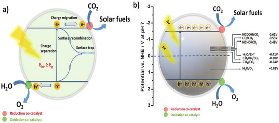
Figure 1.
(a) Diagram depicting the fundamental processes of photogenerated charge carriers on the photocatalytic surface. (b) Diagram illustrating the conversion of CO2 and H2O into solar fuels using a semiconducting photocatalyst, facilitated by appropriate redox co-catalysts. Reproduced with permission from ref. [45]. Copyright, Elsevier, Amsterdam, The Netherlands.
As for the various polymorphs, anatase is often considered the most effective polymorph for photocatalytic applications due to its higher conduction band edge, which provides greater reduction potential for electron transfer reactions, and its lower rates of electron–hole recombination compared to rutile, enhancing the lifetime of charge carriers and improving photocatalytic efficiency. Additionally, anatase typically forms smaller particles with a larger surface area, increasing the number of active sites available for photocatalytic reactions. The highly reactive {001} facets of anatase, which can be synthesized to expose a high percentage of these facets, further boost its photocatalytic performance. Rutile, another important polymorph of TiO2, is generally considered less effective due to its lower conduction band edge and higher rates of electron–hole recombination, though it is more thermodynamically stable at larger particle sizes. Brookite, less commonly used due to its complex synthesis and less-studied properties, has a similar band gap to anatase and unique surface properties that may offer specific advantages in certain reactions. Overall, anatase is typically preferred for photocatalytic applications due to its superior electronic structure, lower recombination rates, and higher surface area, but combining anatase with rutile can sometimes yield synergistic effects by facilitating charge separation and improving efficiency. The choice of polymorph should be guided by the specific requirements of the intended photocatalytic application, with potential benefits from the inclusion of rutile or brookite in certain contexts.
Traditional heterojunctions, including type–I, type–II, and type–III, are categorized according to energy band position relationships, as shown in Figure 2, in which the energy band structures of photocatalyst I (PC I) and photocatalyst II (PC II) are embedded. Under visible light irradiation, photogenerated electrons and holes in the CB and VB of PC I are transferred to the CB and VB of PC II, respectively. Type–I heterojunctions cannot effectively improve photocatalytic performance owing to the rapid recombination of carriers accumulated in the semiconductor. The energy band structure of a type–III heterojunction is completely staggered, and this heterojunction has rarely been reported. Therefore, only type–II heterojunctions are described in this review. Type–II comprises two semiconductors with relatively interleaved band positions. The CB of PC I is more negative than that of PC II, whereas the VB of PC II is more positive than that of PC I [46]. Two different carrier transfer pathways may occur depending on the difference in EF values. The first pathway occurs in the traditional type-II heterojunction when PC I has a high CB but low EF. When the two semiconductors are in contact, their electrons diffuse, thereby forming an IEF with a direction from PC II to PC I. Next, the energy band of PC I bends downward, whereas that of PC II bends in the opposite direction, and EF is in equilibrium. Upon illumination, the photo-generated electrons are transferred from the CB of PC I to that of PC II, and the holes are transferred from the VB of PC II to that of PC I. Thus, the photo-generated electron–hole pairs are effectively separated, thereby improving the photocatalytic activity. The second pathway is a direct Z–scheme when PC I has a high CB and EF. In this case, we obtain the opposite IEF to that of the previous case. The photogenerated electrons are transferred from the CB of PC II to the VB of PC I after illumination. The holes in the VB of PC I after illumination transfer to the CB of PC II [47]. Meanwhile, the electrons in the CB of PC I and the holes in the VB of PC II do not participate in the carrier complex; however, they participate in the redox reaction, thereby forming spatial separate oxidation and reduction active sites, respectively. The traditional type-II heterojunction has good charge separation efficiency; however, its redox capability is lower than that of the direct Z–scheme. For traditional type-II heterojunction, the photo-generated electrons accumulate in the CB of PC II with a weak reduction potential, whereas the photo-generated holes accumulate in the VB of PC I with a weak oxidation potential [48]. The direct Z–scheme benefits from the superior CB and VB for redox reactions and possesses high carrier separation efficiency and strong redox ability. Type–II heterojunctions are the most widely used because of their simplicity of construction.
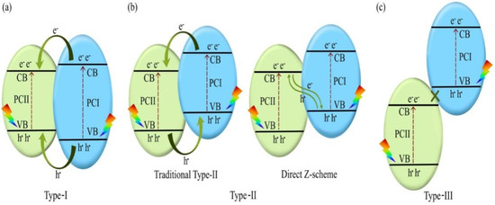
Figure 2.
Photocatalytic mechanism of (a) type-I, (b) type-II, and (c) type–III heterojunctions. Reprinted with permission from [49]. Copyright 2022, Elsevier, Amsterdam, The Netherlands.
The traditional Z–scheme is also known as the liquid phase heterojunction. As shown in Figure 3a, the electrons of the CB of PC II, with a low energy band position, are captured by A, which is subsequently reduced to D. Similarly, the holes of the VB of PC I are captured by D, which is oxidized back to A, thereby completing the cycle. However, because the electron potential difference of PC I is larger than that of PC II, the electrons in PC I are more likely to participate in the reduction of A. Simultaneously, the holes in PC II are more likely to be involved in the oxidation of D. The traditional Z–scheme has limited prospects and was phased out because of its complicated structure, high uncertainty, and narrow range of application. As depicted in Figure 3b, the all-solid-state Z–scheme achieves the complexation of electrons in the CB of PC II and holes in the VB of PC I using electron mediators. The strongly reducing electrons and strongly oxidizing holes remaining in the CB and VB of PC II participate in the reduction and oxidation reactions, respectively. As shown in Figure 3c, a semiconductor with a high energy band position also has a high EF, which is necessary for constructing a direct Z–scheme. This results in the retention of useful redox-competent photogenerated electrons and holes in the CB of PC I and VB of PC II, whereas other photogenerated carriers are involved in carrier complexation. Therefore, the direct Z–scheme solves the problem of carrier complexation while retaining a strong redox ability. However, the solid–solid interfacial resistance of the direct Z–scheme is usually higher than that of the second–generation all-solid Z–scheme, owing to the direct contact between the two semiconductors, which is unsatisfactory. This can be improved by optimizing the solid–solid interface contact to a tight contact for increasing the conductivity [50]. The S–scheme is a good alternative to the direct Z–scheme to avoid the failures caused by the ancestors of the Z–scheme family [51]. The carrier motion mechanism of the S-scheme, shown in Figure 3d, is the same as that of the direct Z–scheme. Therefore, the novelty of the S–scheme heterojunction is uncertain when considering the carrier motion mechanism. The RPs possess higher band positions than those of the OPs. The S–scheme heterojunctions consist of one RP and one OP, where the RP possesses a higher EF than that of the OP.

Figure 3.
Photocatalytic mechanism of the (a) traditional Z–scheme, (b) all–solid-state Z–scheme, (c) direct Z–scheme, and (d) S–scheme. (a) Reprinted with permission from [52]. Copyright 2022 Elsevier (b) Reprinted with permission from [53]. Copyright 2022, Elsevier, Amsterdam, The Netherlands.
3. Structures of TiO2
Many studies have been devoted to modifying the structure of TiO2 in terms of dimensions for the enhancement of photocatalytic activity. Figure 4 displays structured TiO2 possessing various dimensions and morphologies. These TiO2–based materials with various structures will not only enhance their photocatalytic performance, but also form a platform to decorate with other materials, such as metal particles, metal oxides, and semiconductors, to improve the photocatalytic performance [54,55,56,57]. Some parameters of TiO2 structures will affect the photocatalytic performance, including size, surface area, and surface chemical state [58,59,60]. TiO2 particles with optimized size will improve the photocatalytic activities owing to their size-related properties. Meanwhile, the band structure of nanoscale TiO2 is quite different from that of bulk TiO2, owing to the quantum effect [61]. Furthermore, nanosized catalysts will also reduce the electron–hole recombination rate owing to the shorter carrier transfer distance. Up to now, the stability of variously structured TiO2 has been researched. Rutile TiO2 is quite stable with a size larger than 35 nm, while anatase TiO2 is more stable around 11 nm. Moreover, high crystallinity is another crucial factor in facilitating the photoinduced charge carrier transfer. Thus, calcination at a suitable temperature is always necessary to improve crystallinity. Furthermore, a high specific surface area of TiO2 materials will help to improve photocatalytic efficiency by providing more surface sites that facilitate reactions, thus improving reactant adsorption and desorption during the reaction [62,63,64]. Based on previous reports, it has been proved that the photocatalytic performance of TiO2 nanotube is about twice that of pristine TiO2. In addition, 2D nanosheet structures have been explored to enhance photocatalytic activity. Theoretical and experimental research has proven that the {001} facet is much more active than the {101} facet. Yang et al. synthesized an anatase TiO2 single crystal material with 47% {001} facet using hydrofluoric acid as a controlling agent. Subsequently, sheet-like TiO2 materials with 90% exposed {001} facet have been developed. Meanwhile, the specific surface area is another crucial factor in improving active sites for the photocatalysis reaction. Hu et al. reported a kind of {001} facet-rich TiO2 nanosheet with a specific surface area of 162.4 m2·g−1, exhibiting twice higher photocatalytic performance than P25 [65]. Other 3D TiO2 structures, such as hollow fibers, connected structures, and hierarchical structures, have also been researched to achieve efficient catalysts.
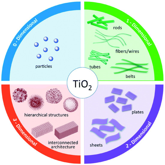
Figure 4.
Schematic structures of TiO2 nanostructures according to structural dimensionality. Reproduced with permission from ref. [66]. Copyright, Royal Society of Chemistry Group, London, UK.
4. Structural Design of Various Dimensions of TiO2 Catalysts with Different Heterostructures
Until now, many strategies have been developed to prepare the 0D, 1D, 2D, and 3D nanostructures with various morphologies, including nanoparticles, nanofibers, nanotubes, and flower–like structures, all of which had been reported in previous articles. This part will summarize the main preparation methods, such as hydrothermal, sol–gel, vapor deposition, and electrospinning [67,68,69,70].
4.1. Hydrothermal Method
The hydrothermal method is typically operated in the autoclave system, known as a sealed Teflon–lined autoclave housed within the stainless steel vessel. When heated in an oven, the inner temperature of the Teflon–lined autoclave will increase beyond the boiling point of the solution, producing high pressure [71]. Various dimensional TiO2 materials can be achieved under these conditions. Figure 5 displays the wire-like TiO2 catalysts synthesized by the hydrothermal method. The synthesis of structured TiO2 materials has recently been regarded as an effective technique for producing large quantities of TiO2 materials with various dimensions in aqueous solutions [72]. Regarding the reagents applied during the hydrothermal synthesis, the method is divided into the acid hydrothermal and alkali hydrothermal methods. For the former method, the reagents often include titanium salts with acid, leading to the formation of 1D TiO2 wire–like structures. The latter method is often used to synthesize TiO2 nanoparticles. Various mechanisms have been researched for these two methods, yielding different morphologies.

Figure 5.
SEM images of TiO2 nanowires prepared by the hydrothermal method (a,b), and HCl aqueous solution layer (c,d) Reproduced with permission from ref. [73]. Copyright, Royal Society of Chemistry Group, London, UK.
4.2. Sol–Gel Method
Meanwhile, the sol–gel method is another effective technique for synthesizing TiO2 particles, involving the hydrolyzation of materials using a titanium precursor. For example, in the synthesis of 1D TiO2 nanowires, confinement is always needed to realize the growth of the 1D structure. Typically, TiO2 nanowires are synthesized using the sol–gel method, with titanium(IV) isopropoxide serving as the precursor. The as–synthesized TiO2 nanowires have a diameter of approximately 10 nm [74,75,76]. Through the sol–gel method, TiO2 particles coalesce to form TiO2 nanowires. Jin et al. synthesized TiO2 nanowires with titanium tetraisopropoxide, isopropanol, and acetic acid as the precursors [77]. To obtain the xerogel, the as-prepared sol was then dried in an oven for one day. Finally, the samples were calcined in a tube furnace at 600 °C with a suitable gas to obtain the well-crystallized TiO2 nanowires.
4.3. Vapor Deposition Method
The vapor deposition method, also known as chemical vapor deposition (CVD) and physical vapor deposition (PVD) method, has been used to prepare high-purity 2D TiO2 materials. Compared with other methods, TiO2 materials prepared by CVD and PVD show higher purity and crystallinity. Kamat et al. have synthesized a kind of well–crystallized TiO2 by CVD (Figure 6). The as-prepared TiO2 nanorods were deposited on an FTO glass with a suitable height [78]. Nevertheless, this method is also limited by the high costs associated with large-scale production.
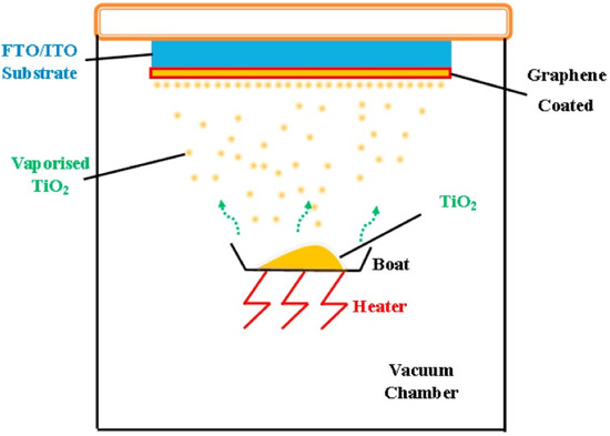
Figure 6.
Display of the vapor deposition method. Reproduced with permission from ref. [79]. Copyright, Elsevier, Amsterdam, The Netherlands.
4.4. Electrospinning Method
Compared to the methods mentioned earlier, the electrospinning method is regarded as a simpler approach for the large-scale synthesis of TiO2 catalysts, especially suited for the preparation of TiO2 nanofibers [80,81,82,83]. This method uses an electric field to transform the precursors into fine fibers. Compared to the previous heating method, the electrospinning process involves four main steps: (1) forming an aqueous solution with titanium precursors; (2) adding a polymer to form a sol suitable for electrospinning; (3) electrospinning the precursors to produce the nanofibers; (4) calcining the as-synthesized nanofibers to obtain highly crystalline TiO2 fibers [84,85,86]. Kim et al. synthesized electrospun TiO2 fibers with various TiO2 percentages (Figure 7) [87]. The average diameter of the TiO2 fibers can vary from 100 to 500 nm by adjusting the parameters.

Figure 7.
Display of preparing TiO2 nanofibers by electrospinning method. Reproduced with permission from ref. [88]. Copyright, Elsevier, Amsterdam, The Netherlands.
5. Photocatalytic Application of Various Dimensions of TiO2-Based Catalysts
The goal in developing catalysts is to synthesize various morphologies that increase the surface area and provide more active sites. To date, TiO2-based catalysts of various dimensions (0D, 1D, 2D, and 3D) have been successfully synthesized. Meanwhile, the combination of metals, semiconductors, and elements doped with TiO2 is considered a useful approach to designing novel TiO2–based catalysts, which enhance light conversion efficiency for photocatalytic applications. Furthermore, the utilization of the structure of TiO2-based catalysts is limited, as will be discussed below (Table 1).

Table 1.
Advantages and disadvantages of various TiO2 preparation methods.
5.1. Zero-Dimensional TiO2-Based Catalysts
As shown in Figure 8a, four different 0D TiO2 catalysts were synthesized with Au particles to investigate the influence of these particles on photocatalytic performance. The synthesis process typically involves using hydrofluoric acid to control the morphology of TiO2. Hydrofluoric acid promotes the exposure of the {001} facet, thereby enhancing photocatalytic activity due to the high percentage of reactive Ti centers. Figure 8b displays SEM images of TiO2 spheres, each with a diameter of 200 nm, illustrating their uniform size and shape. The deposition of Au particles on TiO2 spheres, visible in Figure 8c, further enhances photocatalytic efficiency by facilitating electron transfer. Figure 8d,e show the formation of a core–shell structure in the Au/TiO2 catalysts prepared by the hydrothermal method, which is highlighted as a simple yet effective technique for tuning core–shell structures. This method not only improves the structural integrity of the catalyst but also optimizes its photocatalytic properties. Our analysis suggests that the combination of morphological control through hydrofluoric acid and the structural benefits of the hydrothermal method significantly enhances the performance of TiO2-based photocatalysts.
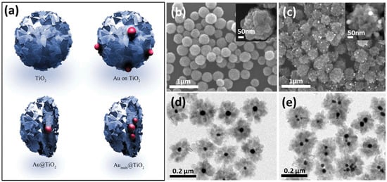
Figure 8.
(a) Display of the four kinds of TiO2 spheres. SEM images of (b) TiO2 particles and (c) TiO2/Au sphere. (d,e) TEM images of Au/TiO2 nanoparticles [89]. Copyright, Royal Society of Chemistry Group, London, UK.
In Figure 9a, core–shell-structured TiO2 catalysts were synthesized with the addition of a sacrificial agent, a configuration often utilized in photocatalytic applications. Previous studies have demonstrated that this unique structure enhances photocatalytic performance [90,91,92,93]. Furthermore, the incorporation of gold (Au) onto TiO2 catalysts, as depicted in Figure 9b, has shown a remarkable 40% increase in hydrogen (H2) production, attributed to leaching effects. The controllable surface structure of these catalysts is crucial for maintaining optimal photocatalytic performance. Various studies have explored the use of TiO2/metal catalysts, such as Au, Pd, and Ag, to improve photocatalytic activity by mitigating electron–hole recombination rates [94,95,96]. In these configurations, photo-induced electrons migrate to the metal due to their lower Fermi levels, while holes remain stable on TiO2 surfaces, thereby enhancing carrier lifetimes and overall photocatalytic efficiency.
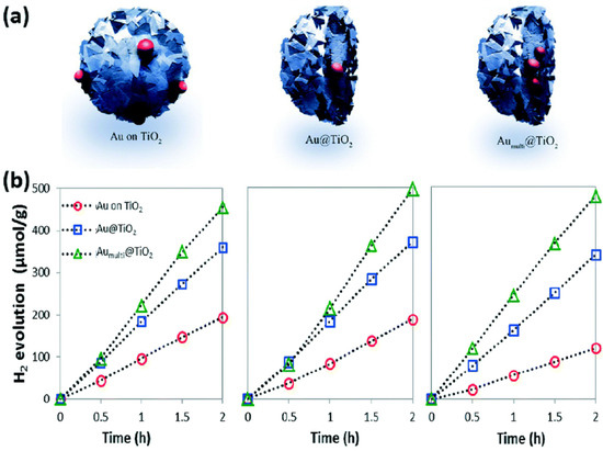
Figure 9.
(a) Display of the three designs of TiO2 particles prepared with Au particles. (b) Photocatalytic performance of H2 evolution cycles of Au on TiO2 and Au/TiO2 [89]. Copyright, Royal Society of Chemistry Group, London, UK.
In recent advancements, the construction of quantum-scale catalytic regions on anatase TiO2 nanoparticles has been achieved by loading TiO2 quantum dots (QDs) onto their surfaces. Figure 10 from the study by Zhou et al. provides a detailed visual representation of this nanostructure. The transmission electron microscopy (TEM) images reveal that the TiO2 nanoparticles are uniformly sized, with an average diameter of approximately 20 nm, and maintain their shape consistently across different samples (Figure 10A,B). The TiO2-QD1 sample, in particular, stands out, as it displays a significant number of 1–3 nm TiO2 QDs on its surface, as indicated by the red arrows in the images (Figure 10C).
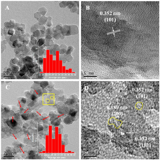
Figure 10.
TEM of TiO2 (A) and TiO2-QD1 (C); HR-TEM of 2 (B) and 2-QD1 (D) ((D) corresponds to the yellow square region in (C)) [97]. Copyright, Elsevier, Amsterdam, The Netherlands.
These QDs are formed through the hydrolysis and condensation of titanium isopropoxide absorbed on the surfaces of the TiO2 nanoparticles, a process that does not alter the primary size and morphology of the TiO2 nanoparticles. High-resolution TEM (HR-TEM) images further confirm the successful integration of these quantum dots, showing lattice fringes corresponding to the {101} and {200} crystal facets of anatase TiO2 (Figure 10D). The presence of these QDs significantly enhances the photocatalytic properties of the TiO2 nanoparticles by providing additional active sites for reactions and facilitating more efficient charge separation. The incorporation of TiO2 QDs onto the nanoparticle surface creates a synergistic effect, improving the photocatalytic degradation of volatile organic compounds (VOCs) such as toluene. This is attributed to the formation of quantum-scale catalytic regions, which increase the reaction probability of electron–hole pairs and their corresponding intermediates. Such advancements in nanostructure engineering highlight the potential of 0D TiO2-based materials in environmental applications, particularly in the photocatalytic degradation of pollutants.
Figure 11 from the research provides an in-depth schematic representation of the band structure and the reaction mechanism within the TiO2–QD composite. This scheme elucidates the intricate processes occurring at the interface between the TiO2 quantum dots (QDs) and the TiO2 nanoparticles. The electron redistribution at this interface is crucial, leading to the formation of an upward band bending from the inner TiO2 particles to the surface TiO2 QDs. This band bending plays a pivotal role in promoting the accumulation of photogenerated holes at the QD side while the electrons accumulate at the TiO2 particle side.
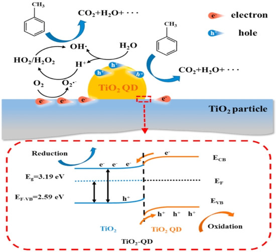
Figure 11.
Schematic of the band structure of TiO2–QD and reaction mechanism [97]. Copyright, Elsevier, Amsterdam, The Netherlands.
The enhanced charge separation due to this band bending significantly improves the photocatalytic activity of the composite. The photogenerated holes, now concentrated on the QD side, are highly effective in oxidizing adsorbed pollutants such as water and toluene, leading to the generation of reactive oxygen species (ROS) like hydroxyl radicals. Concurrently, the electrons that migrate to the TiO2 particle side react with oxygen molecules to form superoxide radicals, further contributing to the photocatalytic degradation of pollutants.
Moreover, the quantum-scale active regions created by the TiO2 QDs optimize the photocatalytic performance in several ways. First, the close proximity of oxidation and reduction sites within the quantum scale ensures efficient transfer and reaction of intermediates, reducing the recombination rate of electron–hole pairs. Second, the presence of TiO2 QDs increases the number of active sites available for photocatalytic reactions, thereby enhancing the overall reactivity of the composite. Third, the engineered band structure ensures that the photogenerated carriers are effectively separated and utilized, maximizing the quantum efficiency of the photocatalytic process.
5.2. One-Dimensional TiO2–Based Catalysts
The hydrothermal method is widely utilized in the production of one-dimensional (1D) TiO2–based catalysts, as exemplified in Figure 12, which exhibits a spectrum of structures comprising TiO2 nanotubes, nanorods, nanobelts, and nanowires. This technique shows immense potential for generating a multitude of TiO2 configurations with varied dimensions. Over recent years, hydrothermal synthesis of TiO2 structured materials has emerged as a highly efficient technique for generating substantial quantities of TiO2 with customized dimensions in aqueous solutions. Notably, the hydrothermal synthesis process can be classified into acid and alkali hydrothermal methods, each characterized by distinct reagents and resulting outcomes [98,99,100,101]. In acid hydrothermal synthesis, titanium salts are typically combined with acidic reagents, yielding the formation of 1D TiO2 wire-like structures. Conversely, alkali hydrothermal methods are preferred for the synthesis of TiO2 nanoparticles. Detailed mechanistic investigations into these methods have unveiled a plethora of pathways governing the formation of diverse morphologies. This comprehensive understanding contributes to optimizing TiO2 catalyst design and performance, enhancing their efficacy in various applications.
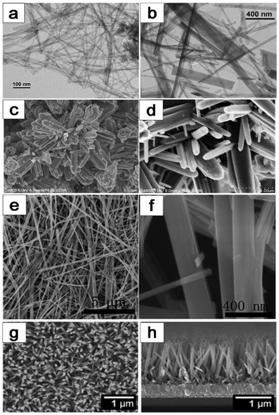
Figure 12.
Various morphologies of 1D TiO2 catalysts prepared by hydrothermal method: (a,b) TiO2–based nanotubes, (c,d) TiO2–based nanorods, (e,f) TiO2-based nanobelts, (g,h) TiO2-based nanowires [1]. Copyright, Royal Society of Chemistry Group, London, UK.
As illustrated in Figure 13a–d, core–shell TiO2 nanowires exhibit significantly enhanced photocatalytic activity compared to both TiO2 nanowires and P25, primarily attributed to their high surface area and improved separation efficiency of charge carriers. Comprehensive measurements have confirmed the transfer of electron–hole pairs on the surface of TiO2 nanowires. Specifically, Figure 13e,f demonstrate that the core–shell TiO2 nanowire heterostructure displays superior photoactivity due to the enhanced rate of electron–hole separation, leading to a prolonged lifetime of charge carriers. This observation underscores the critical role of heterostructuring in optimizing the performance of TiO2-based photocatalysts by facilitating efficient charge separation and minimizing recombination losses. The findings highlight the potential of core–shell nanostructures as a promising avenue for enhancing the photocatalytic efficiency of TiO2 nanowires, offering insights for the design and development of advanced photocatalytic materials for various environmental and energy-related applications.

Figure 13.
(a,c) SEM and HRTEM images of TiO2 nanowires. (b,d) SEM and TEM images of core–shell TiO2 nanowires. (e,f) Photocatalytic performance of various TiO2 catalysts [102]. Copyright, American Chemical Society, Washington, DC, USA.
As displayed in Figure 14, silver (Ag) nanocrystals with an approximate diameter of 3.8 nm were uniformly dispersed across the surface of TiO2 nanotubes (Figure 14a,b). The Ag/TiO2 nanotube composite demonstrated significantly higher visible light photocatalytic activity for the degradation of rhodamine B (RhB) compared to P25 and pure TiO2 nanotubes. Remarkably, this composite could almost completely degrade 100% of RhB within 2 h. This superior performance is attributed to the surface plasmon resonance (SPR) effect of Ag nanocrystals, which enhances visible light absorption, coupled with the high adsorption capacity of TiO2 nanotubes due to their large specific surface area (Figure 14c,d). Additionally, TiO2@carbon core/shell nanofibers (TiO2@C NFs) with varying carbon layer thicknesses were synthesized through a combination of electrospinning and hydrothermal methods. By adjusting the parameters of the hydrothermal fabrication process, the thickness of the carbon layers was precisely controlled, ranging from 2 to 8 nm. These TiO2@C NFs exhibited improved photocatalytic efficiency for RhB degradation under visible light irradiation compared to pure TiO2 nanofibers. This enhancement is likely due to the synergistic effect between the carbon acting as a sensitizer and the 1D structure of TiO2, which facilitates high separation efficiency of photogenerated electrons and holes. Notably, TiO2@C NFs with a 2 nm thick carbon layer exhibited higher photocatalytic activity than those with an 8 nm thick carbon layer (Figure 14e–h). The enhanced photocatalytic activity of Ag/TiO2 nanotube composites can be primarily attributed to the SPR effect of Ag nanocrystals. This effect leads to increased absorption of visible light, which is crucial for photocatalytic processes. Furthermore, the large specific surface area of TiO2 nanotubes allows for greater adsorption of RhB molecules, making the degradation process more efficient. The uniform distribution of Ag nanocrystals ensures that the SPR effect is maximized across the entire surface of the nanotubes, leading to consistent and efficient photocatalysis. In the case of TiO2@C NFs, the carbon layer plays a critical role in enhancing photocatalytic performance. As an excellent conductor, carbon helps in the rapid transfer of photogenerated electrons, reducing the recombination rate of electron–hole pairs. This improved charge separation is essential for higher photocatalytic efficiency. The ability to control the thickness of the carbon layer is particularly advantageous, as it allows for optimization of the photocatalytic properties. A thinner carbon layer (2 nm) provides a better balance between light absorption and electron transfer, leading to superior photocatalytic activity compared to a thicker layer (8 nm). Overall, these findings highlight the significant potential of Ag/TiO2 nanotube composites and TiO2@C NFs in environmental applications, particularly in the degradation of organic pollutants under visible light. The combination of SPR effects, high specific surface area, and efficient charge separation mechanisms provides a robust framework for developing advanced photocatalytic materials. Future research could focus on further optimizing these composites, exploring their applications in other types of pollutants, and scaling up the synthesis processes for industrial applications.
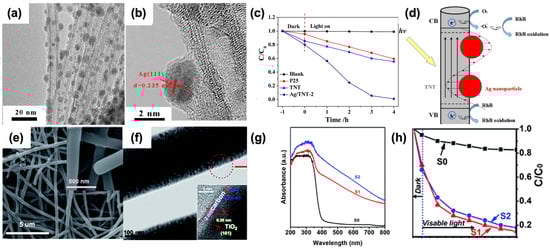
Figure 14.
TEM images of Ag/TiO2 nanotubes (a,b). Visible light photocatalytic degradation curves of rhodamine B over P25, TiO2 nanotubes, and Ag/TiO2 nanotubes (c). Schematic illustration of the photocatalytic degradation mechanism of rhodamine B over the Ag/TiO2 nanotubes under visible light (d). SEM images (e) and TEM images (f) of S2. UV-Vis diffuse reflectance spectra of the S0, S1, and S2 (g). Degradation profiles of rhodamine B over different samples (h). (S0: Pure TiO2 nanofibers. S1, S2: TiO2@C nanofibers with the thickness of carbon layers about 2 and 8 nm, respectively). Reproduced from ref. [103]. Copyright American Chemical Society (a–d). Reproduced from ref. [104]. Copyright, Royal Society of Chemistry, London, UK (e–h).
5.3. Two-Dimensional TiO2–Based Catalysts
Figure 15 illustrates the synthesis procedure of graphene/TiO2/Fe composite catalysts, a process that draws inspiration from numerous reports detailing the synthesis of composite catalysts via the hydrothermal method. Motivated by the success of this approach, we synthesized graphene/TiO2/Fe composite catalysts by incorporating Fe3+ as an additive. Subsequently, we employed the hydrothermal method to synthesize these composite catalysts, during which graphene oxide underwent reduction to form graphene. This strategy capitalizes on the unique properties of graphene and the catalytic capabilities of TiO2 and Fe, with the hydrothermal method serving as a versatile and effective technique for the integration of these components into a synergistic composite structure. By elucidating the synthesis procedure in detail, we aim to provide insights into the rational design and fabrication of graphene–based composite catalysts, offering potential avenues for enhancing their performance in various catalytic applications.
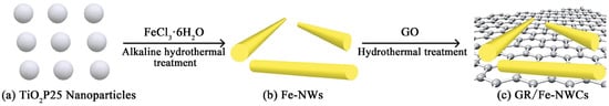
Figure 15.
Illustration of the synthesis process of the graphene/TiO2/Fe composite catalysts [105]. Copyright, Royal Society of Chemistry Group, London, UK.
The SEM images presented in Figure 16 provide valuable insights into the morphology of the synthesized samples. A comparative analysis reveals distinct differences between the pristine Fe nanowires and P25 (Figure 16a,c) and the samples wherein TiO2 is loaded onto graphene nanosheets via the hydrothermal method, showcasing a notably uniform dispersion (Figure 16b,d). This uniform dispersion suggests that TiO2 readily forms Ti–O–C bonds to connect with graphene, facilitating a strong interaction between the two materials. In contrast, other nanoparticles exhibit less pronounced agglomeration on the graphene nanosheets, indicative of the potential for enhanced dispersion and interfacial interactions. These observations underscore the importance of morphology and interfacial characteristics in determining the performance of composite materials, highlighting the potential of graphene-based TiO2 composites for various applications requiring enhanced catalytic activity and stability.

Figure 16.
(a) SEM image of the Fe nanowires; (b) SEM image of the graphene/TiO2/Fe composites; (c) TEM images of the Fe nanowires; (d) TEM images of the graphene/TiO2/Fe composites [105]. Copyright, Royal Society of Chemistry Group, London, UK.
Figure 17 presents the detailed microstructure and elemental distribution of the synthesized photothermal catalysts, specifically the Au–loaded TiO2 nanoflakes (AT–NFs). The high-resolution transmission electron microscopy (HRTEM) images in Figure 17a,b illustrate the two–dimensional size of the nanoflakes, approximately 80 × 50 nm, with a thickness of around 9 nm. These nanoflakes exhibit a well-defined anatase crystal structure, as evidenced by the lattice fringes observed in Figure 17c, which correspond to the {101} crystal plane of anatase TiO2 with a lattice spacing of 3.52 Å. Additionally, the presence of Au nanoparticles on the TiO2 surface is confirmed by the distinct lattice fringes of Au, identified as the {111} crystal planes with a lattice spacing of 2.36 Å. The scanning transmission electron microscopy (STEM) and energy-dispersive X-ray spectroscopy (EDS) mapping in Figure 17e,f further reveal the distribution of Au nanoparticles on the TiO2 nanoflakes. The brighter areas in the STEM images, which align with the traces of Au in the EDS mapping, confirm the uniform distribution of Au on the TiO2 surface. This uniform distribution is crucial for enhanced photocatalytic activity, as it ensures efficient interaction between the TiO2 and Au nanoparticles.
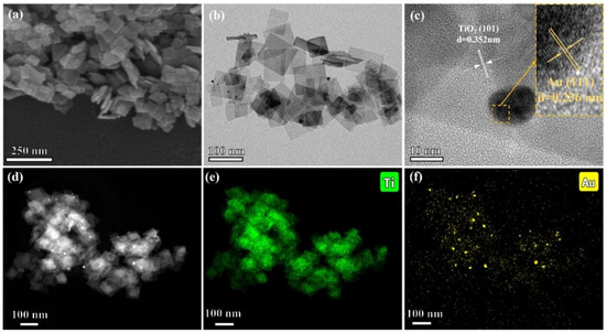
Figure 17.
Images of (a) SEM, (b) HRTEM, (c) lattice fringes, (d) STEM, and (e,f) Ti and Au mapping of AT–NFs [106]. Copyright, Elsevier, Amsterdam, The Netherlands.
Figure 18 explores the impact of the photothermal effect on the hydrogen production efficiency of the synthesized catalysts. The experiments compared the hydrogen evolution rates under photoreforming (PR) and photothermal reforming (PTR) conditions. The results in Figure 18a show that PTR significantly enhances hydrogen production compared to PR. Specifically, after 3 h of irradiation, the hydrogen yield for PTR reached 8.2 mmol/g, which is 58% higher than the 5.2 mmol/g yield observed for PR. Temperature monitoring of the catalyst suspension under UV–visible light illumination, shown in Figure 18b, revealed a significant rise in temperature due to the local surface plasmon resonance (LSPR) effect of the Au nanoparticles. The temperature of the suspension increased from an initial 25 °C to 48.1 °C under full–spectrum light, demonstrating the efficient photothermal conversion. This temperature increase was directly correlated with an enhanced hydrogen evolution rate, which rose with increasing temperature, peaking at 4.2 mmol/g/h at 65 °C, as shown in Figure 18c. The cyclic performance tests in Figure 18d confirmed the stability and reproducibility of the catalysts. Both PR and PTR exhibited excellent cyclic performance, with PTR consistently yielding higher hydrogen production across multiple cycles. The cyclic tests involved alternating periods of light irradiation and cooling to room temperature, demonstrating the catalysts’ robustness and sustained activity over repeated use.

Figure 18.
Graphs of (a) PR and PTR performance of 10 vol% glycerol and pure water during 3 h irradiation, (b) temperature curves of circumstance and AT–NFs suspension during UV–visible light illumination, (c) hydrogen evolution rate at various temperatures, and (d) cyclic performance of PR and PTR [106]. Copyright, Elsevier, Amsterdam, The Netherlands.
5.4. Three-Dimensional TiO2-Based Catalysts
Figure 19a delineates the synthesis process of the 3D TiO2 film, which involves several sequential steps aimed at achieving a structured and functionalized nanoarchitecture. Initially, a 5 μm thick epoxy template is prepared, possessing a structural unit cell of elongated body-centered tetragonal (BCT) geometry with planar and perpendicular structural periodicities of 1 μm. Subsequently, a high-temperature atomic layer deposition (ALD) procedure is employed to deposit TiO2 onto the template surface. Following this, the epoxy template is removed via thermal decomposition at 500 °C, resulting in the formation of a hollow 3D TiO2 structure through a templating process. Next, a layer of TiN is deposited onto the 3D TiO2 structure using ALD at a temperature of 350 °C. This deposition process yields a film with a distinctive sandwich structure comprising TiN/TiO2/TiN layers. Finally, thermal annealing at 550 °C transforms the TiN layer into N-doped TiO2, resulting in a material with a large specific surface area, as depicted in Figure 19b–d. This synthesis approach demonstrates a systematic strategy for fabricating 3D TiO2 films with tailored nanostructures and functional properties. By incorporating ALD and thermal treatment steps, precise control over the composition, structure, and surface characteristics of the resulting films is achieved. The sequential deposition and annealing processes enable the generation of a hierarchical nanoarchitecture with enhanced surface area and photocatalytic activity, offering potential applications in various fields.

Figure 19.
(a) Illustration of the fabrication of the 3D N–doped TiO2 process; (b) images of a 3D N-doped TiO2 film (625 mm2); (c) cross–sectional image of the 3D N-doped TiO2 film; (d) high resolution of 3D N-doped TiO2 film [107]. Copyright, Royal Society of Chemistry Group, London, UK.
Figure 20 presents an evaluation of the photocatalytic activity and stability of various 3D TiO2 films, assessed through the degradation rate of methylene blue (MB) as a model organic pollutant. Upon irradiation with solar light for 3 h, the degradation percentage of MB using the 3D N–doped TiO2 film is approximately 50%, significantly outperforming other samples. This substantial enhancement in degradation rate underscores the superior photocatalytic performance, facilitated by the enhanced charge separation rate and specific surface area (Figure 20a–c). Furthermore, the degradation ability of the 3D N-doped TiO2 film is 1.5 times higher than that of the pristine TiO2 film and 30% higher than that of the undoped TiO2 film (Figure 20d). Notably, the difference in degradation percentage between undoped and N-doped TiO2 films, regardless of their nanostructured nature, is negligible under irradiation with a solar light simulator. This observation suggests a low N–TiO2 film quantum efficiency due to the decreased photo-induced charge carriers and enhanced recombination rate of electron–hole pairs. Moreover, the enhancement of photocatalytic activity attributed to N doping primarily arises from improved visible light absorption, with the 3D structure further accelerating this enhancement. Additionally, the 3D N-doped TiO2 film exhibits remarkable stability, allowing for repeated use as a highly efficient visible photocatalyst without significant performance degradation (Figure 20e). Even after five cycles of reuse, the 3D structure of the TiO2 film remains intact (Figure 20f), highlighting its robustness and potential for practical applications in water treatment and environmental remediation.
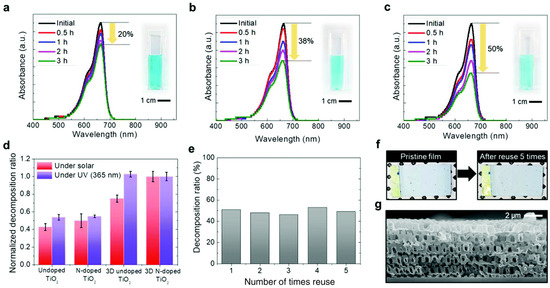
Figure 20.
Photocatalytic performance of a time-dependent absorbance by methylene blue (a) pristine TiO2 film; (b) 3D TiO2 film; (c) 3D N–doped TiO2 film; (d) decomposition performance of MB with the various as prepared TiO2 films; (e) stability of the 3D N-doped TiO2 film; (f) images of the 3D N-doped TiO2 film before and after using 5 times; (g) cross-sectional image of the 3D N-doped TiO2 film after using 5 times [107]. Copyright, Royal Society of Chemistry Group, London, UK.
6. Summary and Perspectives
In this review, we have comprehensively summarized recent advancements in synthesizing various TiO2–based catalysts featuring novel nanostructures. TiO2, owing to its versatile properties, serves as an ideal base material for creating TiO2-based materials with diverse dimensions. The development of various synthesis methods, such as hydrothermal, sol–gel, vapor deposition, and electrospinning, has significantly contributed to this progress. Each of these methods offers unique advantages and challenges in controlling the morphology and size of the TiO2 nanostructures, with the annealing temperature playing a crucial role in determining the final properties of the synthesized materials. Significant research efforts have been directed at combining TiO2 with various metal oxides to enhance its photocatalytic performance. These composite materials exhibit improved visible light absorption and reduced electron–hole pair recombination rates, leading to higher photocatalytic efficiency. Integrating innovative synthesis techniques has enabled the design and fabrication of TiO2–based catalysts with optimized structures that enhance their performance in photocatalytic applications. Among the various nanostructured TiO2 materials, 3D TiO2–based materials have garnered particular attention due to their high specific surface area and extended light response wavelength. These characteristics result in superior photocatalytic activity compared to their lower-dimensional counterparts. The 3D structures provide more active sites for photocatalytic reactions and facilitate better charge separation and transport, which are critical for improving the overall efficiency of the catalysts.
Future research in this field should focus on several key areas to further enhance the performance and applicability of TiO2–based photocatalysts. Firstly, developing more efficient and scalable synthesis methods that allow precise control over the morphology and size of TiO2 nanostructures is essential. Exploring new synthesis techniques and optimizing existing ones could produce materials with even higher photocatalytic activity. Secondly, combining TiO2 with other materials, such as novel metal oxides, carbon-based materials, and other semiconductor nanostructures, should be investigated in greater detail. Understanding the interaction mechanisms between TiO2 and these materials at the molecular level could provide insights into designing more effective composite catalysts. Thirdly, the stability and durability of TiO2–based photocatalysts under real–world conditions must be thoroughly examined. Long-term studies and practical applications should be conducted to ensure that these materials can withstand various environmental conditions without significant degradation in performance. Additionally, expanding the range of applications for TiO2–based photocatalysts beyond environmental remediation to include areas such as energy conversion, water splitting, and CO2 reduction could open up new avenues for research. Tailoring the properties of TiO2 nanostructures to meet the specific requirements of these applications will be crucial for their successful implementation. In conclusion, while substantial progress has been made in synthesizing and applying TiO2–based catalysts with novel nanostructures, there remain numerous opportunities for further research and development. By addressing the challenges and focusing on the future directions outlined above, the potential of TiO2–based photocatalysts can be fully realized, leading to significant advancements in various technological and environmental fields.
Author Contributions
Conceptualization, Y.W. and Y.Z.; methodology, L.X.; software, C.S.; validation, C.S., Y.C. and F.Y.; formal analysis, C.S.; investigation, C.S. and L.X.; resources, H.M.; data curation, W.Z.; writing—original draft preparation, C.S. and L.X.; writing—review and editing, C.S., L.X., Y.W. and Y.Z.; visualization, Y.Z.; supervision, Y.W. and Y.Z.; project administration, Y.W.; funding acquisition, Y.W. and Y.Z. All authors have read and agreed to the published version of the manuscript.
Funding
The authors thank the financial supports from the National Natural Science Foundation of China (No. 22302119), Shanghai Pujiang Program (23PJD037), and Shanghai Youth Science and Technology Qiming Star (23YF1412300).
Data Availability Statement
Not applicable.
Conflicts of Interest
The authors declare no conflicts of interest.
References
- Tian, J.; Zhao, Z.; Kumar, A.; Boughton, R.I.; Liu, H. Recent progress in design, synthesis, and applications of one-dimensional TiO2 nanostructured surface heterostructures: Review. Chem. Soc. Rev. 2014, 43, 6920–6937. [Google Scholar] [CrossRef]
- Zarattini, M.; Dun, C.; Isherwood, L.H.; Felten, A.; Filippi, J.; Gordon, M.P.; Zhang, L.; Kassem, O.; Song, X.; Zhang, W.; et al. Synthesis of 2D anatase TiO2 with highly reactive facets by fluorine-free topochemical conversion of 1T-TiS2 nanosheets. J. Mater. Chem. A 2022, 10, 13884–13894. [Google Scholar] [CrossRef]
- Liu, C.W.; Hao, D.R.; Ye, J.; Ye, S.; Zhou, F.L.; Xie, H.B.; Qin, G.W.; Xu, J.T.; Liu, J.; Li, S.; et al. Knowledge-Driven Design and Lab-Based Evaluation of B-doped TiO2 Photocatalysts for Ammonia Synthesis. Adv. Energy Mater. 2023, 13, 2204126. [Google Scholar] [CrossRef]
- Li, X.Y.; Li, C.; Xu, Y.X.; Liu, Q.; Bahri, M.; Zhang, L.Q.; Browning, N.D.; Cowan, A.J.; Tang, J.W. Efficient hole abstraction for highly selective oxidative coupling of methane by Au-sputtered TiO2 photocatalysts. Nat. Energy 2023, 8, 1013–1022. [Google Scholar] [CrossRef]
- Chen, W.-T.; Chan, A.; Sun-Waterhouse, D.; Llorca, J.; Idriss, H.; Waterhouse, G.I. Performance comparison of Ni/TiO2 and Au/TiO2 photocatalysts for H2 production in different alcohol-water mixtures. J. Catal. 2018, 367, 27–42. [Google Scholar] [CrossRef]
- Wang, H.; Qi, H.F.; Sun, X.; Jia, S.Y.; Li, X.Y.; Miao, T.J.; Xiong, L.Q.; Wang, S.H.; Zhang, X.L.; Liu, X.Y.; et al. High quantum efficiency of hydrogen production from methanol aqueous solution with PtCu-TiO2 photocatalysts. Nat. Mater. 2023, 22, 619–626. [Google Scholar] [CrossRef]
- Gao, D.D.; Long, H.Y.; Wang, X.F.; Yu, J.G.; Yu, H.G. Tailoring Antibonding-Orbital Occupancy State of Selenium in Se-Enriched ReSe Cocatalyst for Exceptional H2 Evolution of TiO2 Photocatalyst. Adv. Funct. Mater. 2023, 33, 2209994. [Google Scholar] [CrossRef]
- Chen, C.; Cai, W.M.; Long, M.C.; Zhou, B.X.; Wu, Y.H.; Wu, D.Y.; Feng, Y.J. Synthesis of Visible Light Responsive Graphene Oxide/TiO2 Composites with p/n Heterojunction. ACS Nano 2010, 4, 6425–6432. [Google Scholar] [CrossRef]
- Montalvo, D.; Corro, G.; Bañuelos, F.; Olivares-Xometl, O.; Arellanes, P.; Pal, U. Selective alcohols production through CO photoreduction using CoO/TiO2 photocatalyst exploiting synergetic interactions between Ti, Co and Co. Appl. Catal. B Environ. 2023, 330, 122652. [Google Scholar] [CrossRef]
- Yang, Y.; Gao, P.; Ren, X.; Sha, L.; Yang, P.; Zhang, J.; Chen, Y.; Yang, L. Massive Ti3+ self-doped by the injected electrons from external Pt and the efficient photocatalytic hydrogen production under visible-Light. Appl. Catal. B Environ. 2017, 218, 751–757. [Google Scholar] [CrossRef]
- Lang, Q.; Chen, Y.; Huang, T.; Yang, L.; Zhong, S.; Wu, L.; Chen, J.; Bai, S. Graphene “bridge” in transferring hot electrons from plasmonic Ag nanocubes to TiO2 nanosheets for enhanced visible light photocatalytic hydrogen evolution. Appl. Catal. B Environ. 2018, 220, 182–190. [Google Scholar] [CrossRef]
- Hu, Z.; Wang, X.; Dong, H.; Li, S.; Li, X.; Li, L. Efficient photocatalytic degradation of tetrabromodiphenyl ethers and simultaneous hydrogen production by TiO2-Cu2O composite films in N2 atmosphere: Influencing factors, kinetics and mechanism. J. Hazard. Mater. 2017, 340, 1–15. [Google Scholar] [CrossRef]
- Wang, Y.; Gao, T.; Li, R.; Chen, Y.; Luo, W.; Wu, Y.; Xie, Y.; Wang, Y.; Zhang, Y. Layered deposited MoS2 nanosheets on acorn leaf like CdS as an efficient anti-photocorrosion photocatalyst for hydrogen production. Fuel 2024, 368, 131621. [Google Scholar] [CrossRef]
- Li, R.; Gao, T.; Wang, Y.; Chen, Y.; Luo, W.; Wu, Y.; Xie, Y.; Wang, Y.; Zhang, Y. Engineering of bimetallic Au–Pd alloyed particles on nitrogen defects riched g-C3N4 for efficient photocatalytic hydrogen production. Int. J. Hydrogen Energy 2024, 63, 1116–1127. [Google Scholar] [CrossRef]
- Zhou, F.; Zhang, J.; Zhang, Y.; Wu, Y.; Wang, Y.; Luo, W. Palladium-Copper bimetallic catalysts for electroreduction of CO2 and nitrogenous species. Coord. Chem. Rev. 2024, 509, 215802. [Google Scholar] [CrossRef]
- Tang, W.; Ye, H.; Xie, Y.; Chen, P.H.; Luo, L.X.; Zhang, Y.F. Transition metal bismuth spheres dispersed and anchored in benzene-ring-grafted porous g-C3N4 nanosheets for photocatalytic reduction of CO. Chem. Eng. J. 2023, 478, 147350. [Google Scholar] [CrossRef]
- Zhang, Y.; Park, S.-J. Stabilization of dispersed CuPd bimetallic alloy nanoparticles on ZIF-8 for photoreduction of Cr(VI) in aqueous solution. Chem. Eng. J. 2019, 369, 353–362. [Google Scholar] [CrossRef]
- Zhang, P.; Song, T.; Wang, T.; Zeng, H. Fabrication of a non-semiconductor photocatalytic system using dendrite-like plasmonic CuNi bimetal combined with a reduced graphene oxide nanosheet for near-infrared photocatalytic H2 evolution. J. Mater. Chem. A 2017, 5, 22772–22781. [Google Scholar] [CrossRef]
- Zhang, P.; Wang, T.; Zeng, H. Design of Cu-Cu2O/g-C3N4 nanocomponent photocatalysts for hydrogen evolution under visible light irradiation using water-soluble Erythrosin B dye sensitization. Appl. Surf. Sci. 2017, 391, 404–414. [Google Scholar] [CrossRef]
- Zhang, P.; Song, T.; Wang, T.; Zeng, H. Effectively extending visible light absorption with a broad spectrum sensitizer for improving the H2 evolution of in-situ Cu/g-C3N4 nanocomponents. Int. J. Hydrogen Energy 2017, 42, 14511–14521. [Google Scholar] [CrossRef]
- Park, S.-J.; Lee, S.-Y. A study on hydrogen-storage behaviors of nickel-loaded mesoporous MCM-41. J. Colloid Interface Sci. 2010, 346, 194–198. [Google Scholar] [CrossRef]
- Im, J.S.; Park, S.-J.; Kim, T.; Lee, Y.-S. Hydrogen storage evaluation based on investigations of the catalytic properties of metal/metal oxides in electrospun carbon fibers. Int. J. Hydrogen Energy 2009, 34, 3382–3388. [Google Scholar] [CrossRef]
- Park, S.-J.; Lee, S.-Y. Hydrogen storage behaviors of platinum-supported multi-walled carbon nanotubes. Int. J. Hydrogen Energy 2010, 35, 13048–13054. [Google Scholar] [CrossRef]
- Zhu, K.; Kang, S.-Z.; Qin, L.; Han, S.; Li, G.; Li, X. Novel and Highly Active Potassium Niobate-Based Photocatalyst for Dramatically Enhanced Hydrogen Production. J. Am. Chem. Soc. 2005, 127, 11447–11453. [Google Scholar] [CrossRef]
- Zhang, P.; Song, T.; Wang, T.; Zeng, H. In-situ synthesis of Cu nanoparticles hybridized with carbon quantum dots as a broad spectrum photocatalyst for improvement of photocatalytic H2 evolution. Appl. Catal. B Environ. 2017, 206, 328–335. [Google Scholar] [CrossRef]
- Yu, H.; Xue, Y.; Hui, L.; Zhang, C.; Li, Y.; Zuo, Z.; Zhao, Y.; Li, Z.; Li, Y. Efficient Hydrogen Production on a 3D Flexible Heterojunction Material. Adv. Mater. 2018, 30, e1707082. [Google Scholar] [CrossRef]
- Lin, L.; Ren, W.; Wang, C.; Asiri, A.M.; Zhang, J.; Wang, X. Crystalline carbon nitride semiconductors prepared at different temperatures for photocatalytic hydrogen production. Appl. Catal. B Environ. 2018, 231, 234–241. [Google Scholar] [CrossRef]
- Im, J.S.; Kwon, O.; Kim, Y.H.; Park, S.-J.; Lee, Y.-S. The effect of embedded vanadium catalyst on activated electrospun CFs for hydrogen storage. Microporous Mesoporous Mater. 2008, 115, 514–521. [Google Scholar] [CrossRef]
- Yi, H.; Huang, D.; Qin, L.; Zeng, G.; Lai, C.; Cheng, M.; Ye, S.; Song, B.; Ren, X.; Guo, X. Selective prepared carbon nanomaterials for advanced photocatalytic application in environmental pollutant treatment and hydrogen production. Appl. Catal. B Environ. 2018, 239, 408–424. [Google Scholar] [CrossRef]
- Ji, L.; Lv, C.; Chen, Z.; Huang, Z.; Zhang, C. Nickel-Based (Photo)Electrocatalysts for Hydrogen Production. Adv. Mater. 2018, 30, e1705653. [Google Scholar] [CrossRef]
- Ma, Y.; Dong, X.; Wang, Y.; Xia, Y. Decoupling Hydrogen and Oxygen Production in Acidic Water Electrolysis Using a Polytriphenylamine-Based Battery Electrode. Angew. Chem. 2018, 57, 2904–2908. [Google Scholar] [CrossRef]
- Wang, B.; Zeng, C.; Chu, K.H.; Wu, D.; Yip, H.Y.; Ye, L.; Wong, P.K. Enhanced Biological Hydrogen Production from Escherichia coli with Surface Precipitated Cadmium Sulfide Nanoparticles. Adv. Energy Mater. 2017, 7, 1700611. [Google Scholar] [CrossRef]
- Zhang, Y.; Park, M.; Kim, H.-Y.; Park, S.-J. In-situ synthesis of graphene oxide/BiOCl heterostructured nanofibers for visible-light photocatalytic investigation. J. Alloys Compd. 2016, 686, 106–114. [Google Scholar] [CrossRef]
- Zhang, Y.; Park, M.; Kim, H.Y.; Ding, B.; Park, S.-J. In-situ synthesis of nanofibers with various ratios of BiOClx/BiOBry/BiOIz for effective trichloroethylene photocatalytic degradation. Appl. Surf. Sci. 2016, 384, 192–199. [Google Scholar] [CrossRef]
- Pipitone, G.; Tosches, D.; Bensaid, S.; Galia, A.; Pirone, R. Valorization of alginate for the production of hydrogen via catalytic aqueous phase reforming. Catal. Today 2018, 304, 153–164. [Google Scholar] [CrossRef]
- Lee, S.-Y.; Park, S.-J. Effect of platinum doping of activated carbon on hydrogen storage behaviors of metal-organic frameworks-5. Int. J. Hydrogen Energy 2011, 36, 8381–8387. [Google Scholar] [CrossRef]
- Hibino, T.; Kobayashi, K.; Ito, M.; Ma, Q.; Nagao, M.; Fukui, M.; Teranishi, S. Kinetics of the Interconversion of Parahydrogen and Orthohydrogen Catalyzed by Paramagnetic Complex Ions. J. Am. Chem. Soc. 2005, 127, 11447–11453. [Google Scholar]
- Zhang, P.; Song, T.; Wang, T.; Zeng, H. Plasmonic Cu nanoparticle on reduced graphene oxide nanosheet support: An efficient photocatalyst for improvement of near-infrared photocatalytic H2 evolution. Appl. Catal. B Environ. 2018, 225, 172–179. [Google Scholar] [CrossRef]
- Kim, W.; Monllor-Satoca, D.; Chae, W.-S.; Mahadik, M.A.; Jang, J.S. Enhanced photoelectrochemical and hydrogen production activity of aligned CdS nanowire with anisotropic transport properties. Appl. Surf. Sci. 2019, 463, 339–347. [Google Scholar] [CrossRef]
- Hibino, T.; Kobayashi, K.; Ito, M.; Nagao, M.; Fukui, M.; Teranishi, S. Direct electrolysis of waste newspaper for sustainable hydrogen production: An oxygen-functionalized porous carbon anode. Appl. Catal. B Environ. 2018, 231, 191–199. [Google Scholar] [CrossRef]
- Park, S.; Kim, B.; Lee, Y.; Cho, M. Influence of copper electroplating on high pressure hydrogen-storage behaviors of activated carbon fibers. Int. J. Hydrogen Energy 2008, 33, 1706–1710. [Google Scholar] [CrossRef]
- Im, J.S.; Park, S.-J.; Lee, Y.-S. Superior prospect of chemically activated electrospun carbon fibers for hydrogen storage. Mater. Res. Bull. 2009, 44, 1871–1878. [Google Scholar] [CrossRef]
- Wu, Z.; Zhou, Z.; Zhang, Y.; Wang, J.; Shi, H.; Shen, Q.; Wei, G.; Zhao, G. Simultaneous photoelectrocatalytic aromatic organic pollutants oxidation for hydrogen production promotion with a self-biasing photoelectrochemical cell. Electrochim. Acta 2017, 254, 140–147. [Google Scholar] [CrossRef]
- Kim, B.-J.; Lee, Y.-S.; Park, S.-J. Preparation of platinum-decorated porous graphite nanofibers, and their hydrogen storage behaviors. J. Colloid Interface Sci. 2008, 318, 530–533. [Google Scholar] [CrossRef]
- Chauhan, D.K.; Sharma, N.; Kailasam, K. A critical review on emerging photocatalysts for syngas generation CO reduction under aqueous media: A sustainable paradigm. Mater. Adv. 2022, 3, 5274–5298. [Google Scholar] [CrossRef]
- Yang, K.Y.; Hsu, H.W.; Hsieh, H.Y.; Chang, W.C.; Li, M.C.; Lin, P.C.; Lee, C.C.; Liu, C.L.; Lee, T.C. Facile Spray Deposition of Photocatalytic ZnO/Cu-In-Zn-S Heterostructured Composite Thin Film. Chemistryselect 2016, 1, 4979–4986. [Google Scholar] [CrossRef]
- Krishnan, C.V.; Brunschwig, B.S.; Creutz, C.; Sutin, N. Homogeneous catalysis of the photoreduction of water. 6. Mediation by polypyridine complexes of ruthenium(II) and cobalt(II) in alkaline media. J. Am. Chem. Soc. 1985, 107, 2005–2015. [Google Scholar] [CrossRef]
- Tada, H.; Mitsui, T.; Kiyonaga, T.; Akita, T.; Tanaka, K. All-solid-state Z-scheme in CdS-Au-TiO2 three-component nanojunction system. Nat. Mater. 2006, 5, 782–786. [Google Scholar] [CrossRef]
- Zhao, Y.; Linghu, X.Y.; Shu, Y.; Zhang, J.W.; Chen, Z.; Wu, Y.; Shan, D.; Wang, B.Q. Classification and catalytic mechanisms of heterojunction photocatalysts and the application of titanium dioxide (TiO2)-based heterojunctions in environmental remediation. J. Environ. Chem. Eng. 2022, 10, 108077. [Google Scholar] [CrossRef]
- Li, J.M.; Tsao, C.W.; Fang, M.J.; Chen, C.C.; Liu, C.W.; Hsu, Y.J. TiO2-Au-CuO Photocathodes: Au-Mediated Z-Scheme Charge Transfer for Efficient Solar-Driven Photoelectrochemical Reduction. ACS Appl. Nano Mater. 2018, 1, 6843–6853. [Google Scholar] [CrossRef]
- Liu, J.Z.; Liu, Z.Y.; Piao, C.C.; Li, S.G.; Tang, J.H.; Fang, D.W.; Zhang, Z.H.; Wang, J. Construction of fixed Z-scheme Ag|AgBr/Ag/TiO2 photocatalyst composite film for malachite green degradation with simultaneous hydrogen production. J. Power Sources 2020, 469, 228430. [Google Scholar] [CrossRef]
- Xu, Q.; Zhang, L.; Cheng, B.; Fan, J.; Yu, J. S-Scheme Heterojunction Photocatalyst. Chem 2020, 6, 1543–1559. [Google Scholar] [CrossRef]
- Xu, Q.L.; Zhang, L.Y.; Yu, J.G.; Wageh, S.; Al-Ghamdi, A.A.; Jaroniec, M. Direct Z-scheme photocatalysts: Principles, synthesis, and applications. Mater. Today 2018, 21, 1042–1063. [Google Scholar] [CrossRef]
- Zhang, Y.; Park, S.-J. Incorporation of RuO2 into charcoal-derived carbon with controllable microporosity by CO2 activation for high-performance supercapacitor. Carbon 2017, 122, 287–297. [Google Scholar] [CrossRef]
- Panthi, G.; Park, M.; Kim, H.-Y.; Park, S.-J. Electrospun polymeric nanofibers encapsulated with nanostructured materials and their applications: A review. J. Ind. Eng. Chem. 2015, 24, 1–13. [Google Scholar] [CrossRef]
- Panthi, G.; Park, M.; Kim, H.-Y.; Lee, S.-Y.; Park, S.-J. Electrospun ZnO hybrid nanofibers for photodegradation of wastewater containing organic dyes: A review. J. Ind. Eng. Chem. 2015, 21, 26–35. [Google Scholar] [CrossRef]
- Kim, S.; Park, S. Electroactivity of Pt–Ru/polyaniline composite catalyst-electrodes prepared by electrochemical deposition methods. Solid State Ion. 2008, 178, 1915–1921. [Google Scholar] [CrossRef]
- Park, S.-J.; Kim, B.-J. Influence of oxygen plasma treatment on hydrogen chloride removal of activated carbon fibers. J. Colloid Interface Sci. 2004, 275, 590–595. [Google Scholar] [CrossRef]
- Park, S.-J.; Kim, J.S. Modifications produced by electrochemical treatments oncarbon blacks Microstructures and mechanical interfacial properties. Carbon 2001, 39, 2011–2016. [Google Scholar] [CrossRef]
- Hou, H.; Liu, H.; Gao, F.; Shang, M.; Wang, L.; Xu, L.; Wong, W.-Y.; Yang, W. Packaging BiVO4 nanoparticles in ZnO microbelts for efficient photoelectrochemical hydrogen production. Electrochim. Acta 2018, 283, 497–508. [Google Scholar] [CrossRef]
- Cao, S.; Yu, J. g-C3N4-Based Photocatalysts for Hydrogen Generation. J. Phys. Chem. Lett. 2014, 5, 2101–2107. [Google Scholar] [CrossRef]
- Xu, X.; Si, Z.; Liu, L.; Wang, Z.; Chen, Z.; Ran, R.; He, Y.; Weng, D. CoMoS2/rGO/C3N4 ternary heterojunctions catalysts with high photocatalytic activity and stability for hydrogen evolution under visible light irradiation. Appl. Surf. Sci. 2018, 435, 1296–1306. [Google Scholar] [CrossRef]
- Zhou, J.; Zhao, Y.; Bao, J.; Huo, D.; Fa, H.; Shen, X.; Hou, C. One-step electrodeposition of Au-Pt bimetallic nanoparticles on MoS2 nanoflowers for hydrogen peroxide enzyme-free electrochemical sensor. Electrochim. Acta 2017, 250, 152–158. [Google Scholar] [CrossRef]
- Fang, J.; Gu, J.; Liu, Q.; Zhang, W.; Su, H.; Zhang, D. Three-Dimensional CdS/Au Butterfly Wing Scales with Hierarchical Rib Structures for Plasmon-Enhanced Photocatalytic Hydrogen Production. ACS Appl. Mater. Interfaces 2018, 10, 19649–19655. [Google Scholar] [CrossRef]
- Hu, C.; Zhang, X.; Li, W.; Yan, Y.; Xi, G.; Yang, H.; Li, J.; Bai, H. Large-scale, ultrathin and (001) facet exposed TiO2 nanosheet superstructures and their applications in photocatalysis. J. Mater. Chem. A 2014, 2, 2040–2043. [Google Scholar] [CrossRef]
- Gao, M.; Zhu, L.; Ong, W.L.; Wang, J.; Ho, G.W. Structural design of TiO2-based photocatalyst for H2 production and degradation applications. Catal. Sci. Technol. 2015, 5, 4703–4726. [Google Scholar] [CrossRef]
- Zhang, Y.; Park, S.-J. Facile construction of MoO3@ZIF-8 core-shell nanorods for efficient photoreduction of aqueous Cr (VI). Appl. Catal. B Environ. 2019, 240, 92–101. [Google Scholar] [CrossRef]
- Zhang, Y.; Park, S.-J. Formation of hollow MoO3/SnS2 heterostructured nanotubes for efficient light-driven hydrogen peroxide production. J. Mater. Chem. A 2018, 6, 20304–20312. [Google Scholar] [CrossRef]
- Chang, Y.; Yu, K.; Zhang, C.; Yang, Z.; Feng, Y.; Hao, H.; Jiang, Y.; Lou, L.-L.; Zhou, W.; Liu, S. Ternary CdS/Au/3DOM-SrTiO3 composites with synergistic enhancement for hydrogen production from visible-light photocatalytic water splitting. Appl. Catal. B Environ. 2017, 215, 74–84. [Google Scholar] [CrossRef]
- Masudy-Panah, S.; Siavash Moakhar, R.; Chua, C.S.; Kushwaha, A.; Dalapati, G.K. Stable and Efficient CuO Based Photocathode through Oxygen-Rich Composition and Au-Pd Nanostructure Incorporation for Solar-Hydrogen Production. ACS Appl. Mater. Interfaces 2017, 9, 27596–27606. [Google Scholar] [CrossRef]
- Ortiz, N.; Zoellner, B.; Hong, S.J.; Ji, Y.; Wang, T.; Liu, Y.; Maggard, P.A.; Wang, G. Harnessing Hot Electrons from Near IR Light for Hydrogen Production Using Pt-End-Capped-AuNRs. ACS Appl. Mater. Interfaces 2017, 9, 25962–25969. [Google Scholar] [CrossRef]
- Wang, Y.; Zhao, J.; Li, Y.; Wang, C. Selective photocatalytic CO2 reduction to CH4 over Pt/In2O3: Significant role of hydrogen adatom. Appl. Catal. B Environ. 2018, 226, 544–553. [Google Scholar] [CrossRef]
- Su, J.; Guo, L. High aspect ratio TiO2 nanowires tailored in concentrated HCl hydrothermal condition for photoelectrochemical water splitting. RSC Adv. 2015, 5, 53012–53018. [Google Scholar] [CrossRef]
- Jiang, J.-Z.; Ren, L.-Q.; Huang, Y.-P.; Li, X.-D.; Wu, S.-H.; Sun, J.-J. 3D Nanoporous Gold-Supported Pt Nanoparticles as Highly Accelerating Catalytic Au-Pt Micromotors. Adv. Mater. Interfaces 2018, 5, 1701689. [Google Scholar] [CrossRef]
- Kamijyo, K.; Takashima, T.; Yoda, M.; Osaki, J.; Irie, H. Facile synthesis of a red light-inducible overall water-splitting photocatalyst using gold as a solid-state electron mediator. Chem. Commun. 2018, 54, 7999–8002. [Google Scholar] [CrossRef]
- Yu, X.; Liu, G.; Li, W.; An, L.; Li, Z.; Liu, J.; Hu, P. Mesocrystalline Ta2O5 nanosheets supported Pd Pt nanoparticles for efficient photocatalytic hydrogen production. Int. J. Hydrogen Energy 2018, 43, 8232–8242. [Google Scholar] [CrossRef]
- Yao, Y.C.; Dai, X.R.; Hu, X.Y.; Huang, S.Z.; Jin, Z. Synthesis of Ag-decorated porous TiO nanowires through a sunlight induced reduction method and its enhanced photocatalytic activity. Appl. Surf. Sci. 2016, 387, 469–476. [Google Scholar] [CrossRef]
- Vinodgopal, K.; Kamat, P.V. Enhanced rates of photocatalytic degradation of an azo dye using SnO2/TiO2 coupled semiconductor thin films. Environ. Sci. Technol. 1995, 29, 841. [Google Scholar] [CrossRef]
- Low, F.W.; Lai, C.W. Recent developments of graphene-TiO2 composite nanomaterials as efficient photoelectrodes in dye-sensitized solar cells: A review. Renew. Sustain. Energy Rev. 2017, 82, 103–125. [Google Scholar] [CrossRef]
- Ranjit, K.; Viswanathan, B. Synthesis, characterization and photocatalytic properties of iron-doped TiO2 catalysts. J. Photochem. Photobiol. A 1997, 108, 79–84. [Google Scholar] [CrossRef]
- Monai, M.; Montini, T.; Fonda, E.; Crosera, M.; Delgado, J.J.; Adami, G.; Fornasiero, P. Nanostructured Pd Pt nanoparticles: Evidences of structure/performance relations in catalytic H2 production reactions. Appl. Catal. B Environ. 2018, 236, 88–98. [Google Scholar] [CrossRef]
- Wang, Q.; He, J.; Shi, Y.; Zhang, S.; Niu, T.; She, H.; Bi, Y.; Lei, Z. Synthesis of MFe2O4 (M = Ni, Co)/BiVO4 film for photolectrochemical hydrogen production activity. Appl. Catal. B Environ. 2017, 214, 158–167. [Google Scholar] [CrossRef]
- Fu, J.; Zhu, B.; You, W.; Jaroniec, M.; Yu, J. A flexible bio-inspired H2-production photocatalyst. Appl. Catal. B Environ. 2018, 220, 148–160. [Google Scholar] [CrossRef]
- Li, K.; Gao, S.; Wang, Q.; Xu, H.; Wang, Z.; Huang, B.; Dai, Y.; Lu, J. In-Situ-Reduced Synthesis of Ti(3)(+) Self-Doped TiO(2)/g-C(3)N(4) Heterojunctions with High Photocatalytic Performance under LED Light Irradiation. ACS Appl. Mater. Interfaces 2015, 7, 9023–9030. [Google Scholar] [CrossRef]
- Heo, Y.-J.; Zhang, Y.; Rhee, K.Y.; Park, S.-J. Synthesis of PAN/PVDF nanofiber composites-based carbon adsorbents for CO2 capture. Compos. Part B Eng. 2019, 156, 95–99. [Google Scholar] [CrossRef]
- Zhang, Y.; Park, M.; Kim, H.Y.; Park, S.-J. Moderated surface defects of Ni particles encapsulated with NiO nanofibers as supercapacitor with high capacitance and energy density. J. Colloid Interface Sci. 2017, 500, 155–163. [Google Scholar] [CrossRef]
- Zhang, Y.; Park, M.; Kim, H.-Y.; El-Newehy, M.; Rhee, K.Y.; Park, S.-J. Effect of TiO2 on photocatalytic activity of polyvinylpyrrolidone fabricated via electrospinning. Compos. Part B Eng. 2015, 80, 355–360. [Google Scholar] [CrossRef]
- Lee, E.J.; An, A.K.; Hadi, P.; Lee, S.; Woo, Y.C.; Shon, H.K. Advanced multi-nozzle electrospun functionalized titanium dioxide/polyvinylidene fluoride-co-hexafluoropropylene (TiO2/PVDF-HFP) composite membranes for direct contact membrane distillation. J. Memb. Sci. 2017, 524, 712–720. [Google Scholar] [CrossRef]
- Gao, M.; Peh, C.K.N.; Pan, Y.; Xu, Q.-H.; Ho, G.W. Fine structural tuning of whereabout and clustering of metal–metal oxide heterostructure for optimal photocatalytic enhancement and stability. Nanoscale 2014, 6, 12655–12664. [Google Scholar] [CrossRef]
- Wang, J.; Tafen, D.N.; Lewis, J.P.; Hong, Z.; Manivannan, A.; Zhi, M.; Li, M.; Wu, N. Origin of photocatalytic activity of nitrogen-doped TiO2 nanobelts. J. Am. Chem. Soc. 2009, 131, 12290–12297. [Google Scholar] [CrossRef]
- Braun, A.; Akurati, K.K.; Fortunato, G.; Reifler, F.A.; Ritter, A.; Harvey, A.S.; Vital, A.; Graule, T. Nitrogen doping of TiO2 photocatalyst forms a second e g state in the oxygen 1s NEXAFS pre-edge. J. Phys. Chem. C 2010, 114, 516–519. [Google Scholar] [CrossRef]
- Khan, S.U.M.; Al-Shahry, M.; Ingler, W.B., Jr. Efficient photochemical water-splitting by a chemically modified n-TiO2. Science 2002, 297, 2243–2245. [Google Scholar] [CrossRef]
- Liu, Z.; Guo, K.; Han, J.; Li, Y.; Cui, T.; Wang, B.; Ya, J.; Zhou, C. Dendritic TiO2/ln2S3/AgInS2 trilaminar core-shell branched nanoarrays and the enhanced activity for photo-electrochemical water-splitting. Small 2014, 10, 3153–3161. [Google Scholar] [CrossRef]
- Nakajima, H.; Mori, T.; Watanabe, M. Influence of platinum loading on photoluminescence of TiO2 powder. J. Appl. Phys. 2004, 96, 925–927. [Google Scholar] [CrossRef]
- Wu, G.P.; Chen, T.; Su, W.G.; Zhou, G.H.; Zong, X.; Lei, Z.B.; Li, C. H2 production with ultra-low CO selectivity via photocatalytic reforming of methanol on Au/TiO2 catalyst. Int. J. Hydrogen Energy 2008, 33, 1243–1251. [Google Scholar] [CrossRef]
- Cai, H.; Yang, Q.; Hu, Z.; Zhihua, D.; You, Q.; Sun, J.; Xu, N.; Wu, J. Enhanced photoelectrochemical activity of vertically aligned ZnO-coated TiO2 nanotubes. Appl. Phys. Lett. 2014, 104, 053114. [Google Scholar] [CrossRef]
- Zhou, L.L.; Shen, Z.Z.; Wang, S.B.; Gao, J.X.; Tang, L.L.; Li, J.; Dong, Y.M.; Wang, Z.Y.; Lyu, J. Construction of quantum-scale catalytic regions on anatase TiO2 nanoparticles by loading TiO2 quantum dots for the photocatalytic degradation of VOCs. Ceram. Int. 2021, 47, 21090–21098. [Google Scholar] [CrossRef]
- Gui, Q.; Xu, Z.; Zhang, H.; Cheng, C.; Zhu, X.; Yin, M.; Song, Y.; Lu, L.; Chen, X.; Li, D. Enhanced photoelectrochemical water-splitting performance of anodic TiO2 nanotube arrays by surface passivation. ACS Appl. Mater. Interfaces 2014, 6, 17053–17058. [Google Scholar] [CrossRef]
- Sopha, H.; Krbal, M.; Ng, S.; Prikryl, J.; Zazpe, R.; Yam, F.K.; Macak, J.M. One-dimensional anodic TiO2 nanotubes coated by atomic layer deposition: Towards advanced applications. Appl. Mater. Today 2017, 9, 104–110. [Google Scholar] [CrossRef]
- Naldoni, A.; Montini, T.; Malara, F.; Mroz, M.M.; Beltram, A.; Virgili, T.; Boldrini, C.L.; Marelli, M.; Romero-Ocaña, I.; Delgado, J.J.; et al. Hot electron collection on brookite nanorods lateral facets for plasmon-enhanced water oxidation. ACS Catal. 2017, 7, 1270–1278. [Google Scholar] [CrossRef]
- Cho, I.S.; Chen, Z.; Forman, A.J.; Kim, D.R.; Rao, P.M.; Jaramillo, T.F.; Zheng, X. Branched TiO2 nanorods for photoelectrochemical hydrogen production. Nano Lett. 2011, 11, 4978–4984. [Google Scholar] [CrossRef]
- Yang, D.; Sun, Y.Y.; Tong, Z.W.; Tian, Y.; Li, Y.B.; Jiang, Z.Y. Synthesis of Ag/TiO Nanotube Heterojunction with Improved Visible-Light Photocatalytic Performance Inspired by Bioadhesion. J. Phys. Chem. C 2015, 119, 5827–5835. [Google Scholar] [CrossRef]
- Zhang, P.; Shao, C.L.; Zhang, Z.Y.; Zhang, M.Y.; Mu, J.B.; Guo, Z.C.; Liu, Y.C. TiO@carbon core/shell nanofibers: Controllable preparation and enhanced visible photocatalytic properties. Nanoscale 2011, 3, 2943–2949. [Google Scholar] [CrossRef]
- Liu, B.; Khare, A.; Aydil, E.S. TiO2-B/anatase core-shell heterojunction nanowires for photocatalysis. ACS Appl. Mater. Interfaces 2011, 3, 4444–4450. [Google Scholar] [CrossRef]
- Li, W.; Liu, X.; Li, H. Hydrothermal synthesis of graphene/Fe3+-doped TiO2 nanowire composites with highly enhanced photocatalytic activity under visible light irradiation. J. Mater. Chem. A 2015, 3, 15214–15224. [Google Scholar] [CrossRef]
- Zhong, W.L.; Wang, C.; Zhao, H.L.; Peng, S.Q.; Tian, Z.P.; Shu, R.Y.; Chen, Y. Synergistic effect of photo-thermal catalytic glycerol reforming hydrogen production over 2D Au/TiO2 nanoflakes. Chem. Eng. J. 2022, 446, 137063. [Google Scholar] [CrossRef]
- Cho, S.; Ahn, C.; Park, J.; Jeon, S. 3D nanostructured N-doped TiO2 photocatalysts with enhanced visible absorption. Nanoscale 2018, 10, 9747–9751. [Google Scholar] [CrossRef]
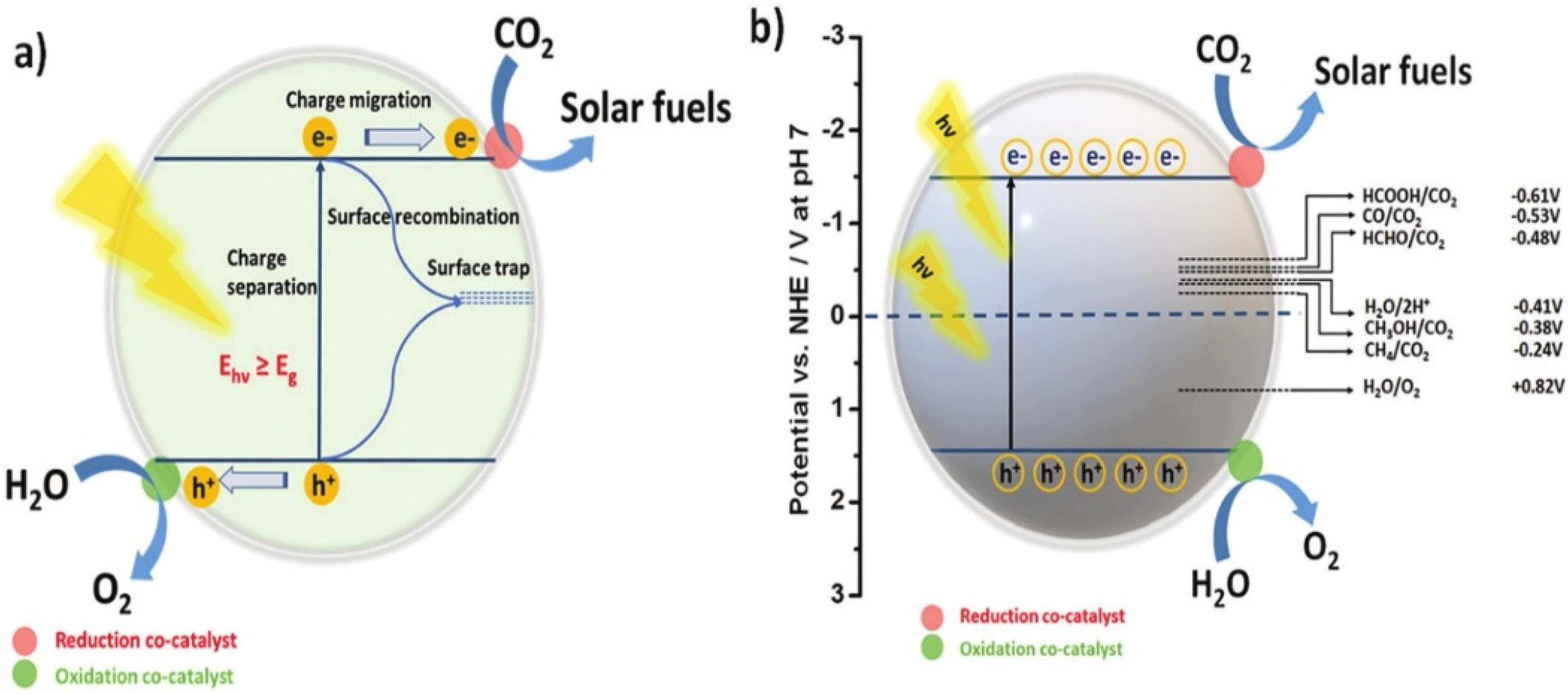
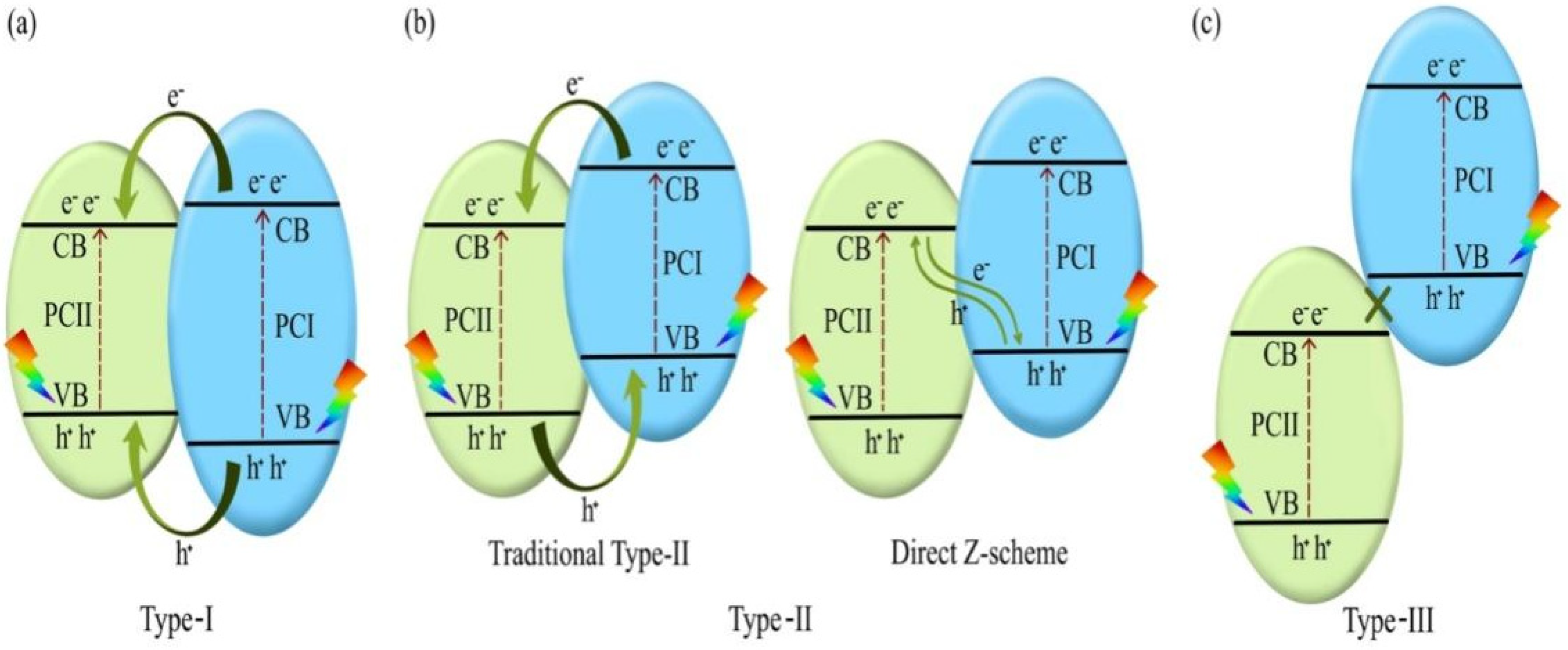
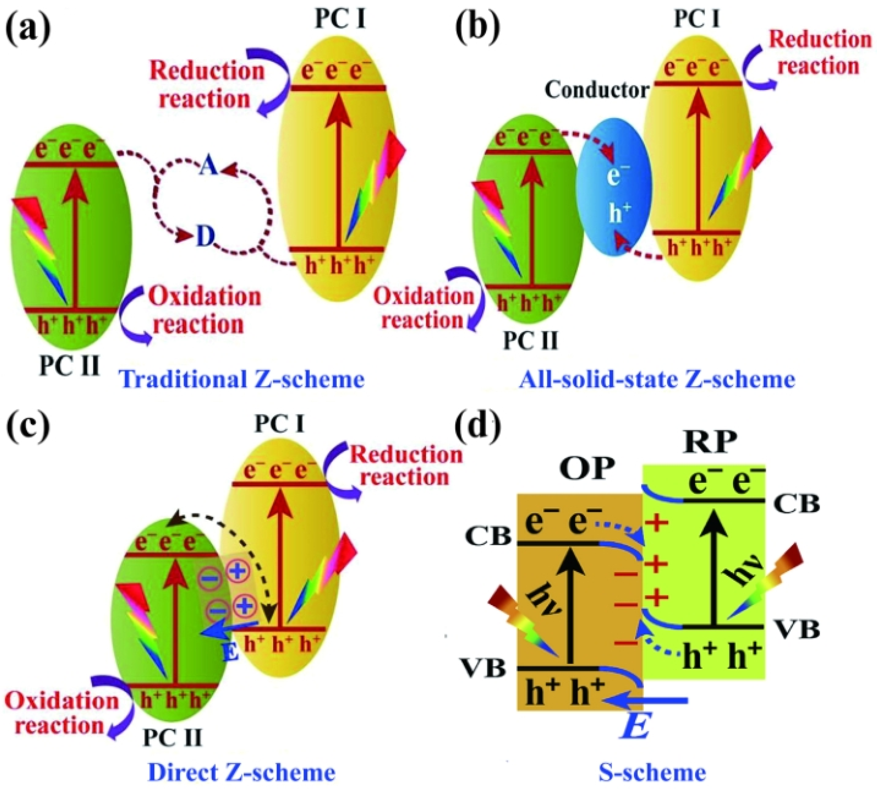
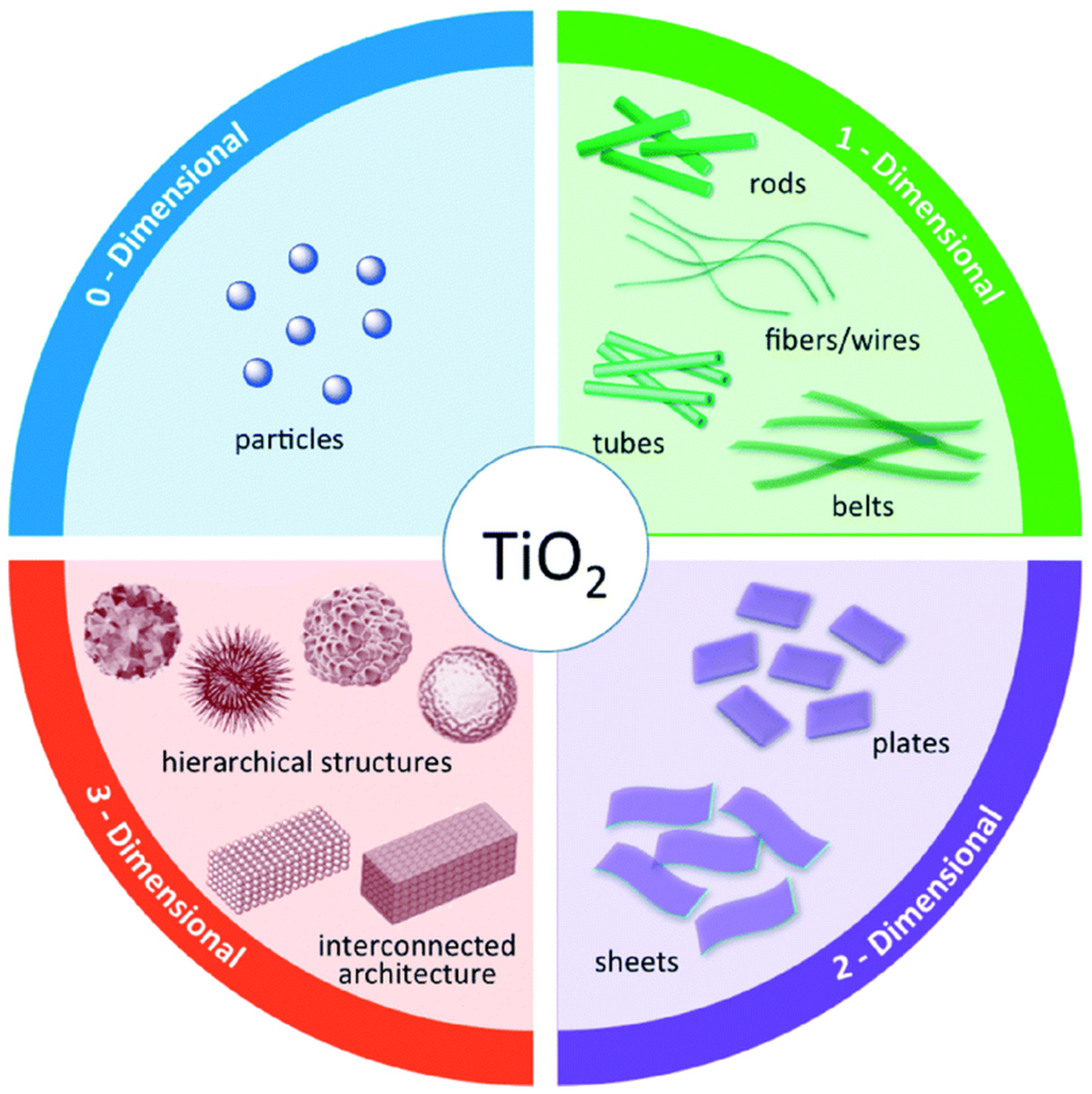
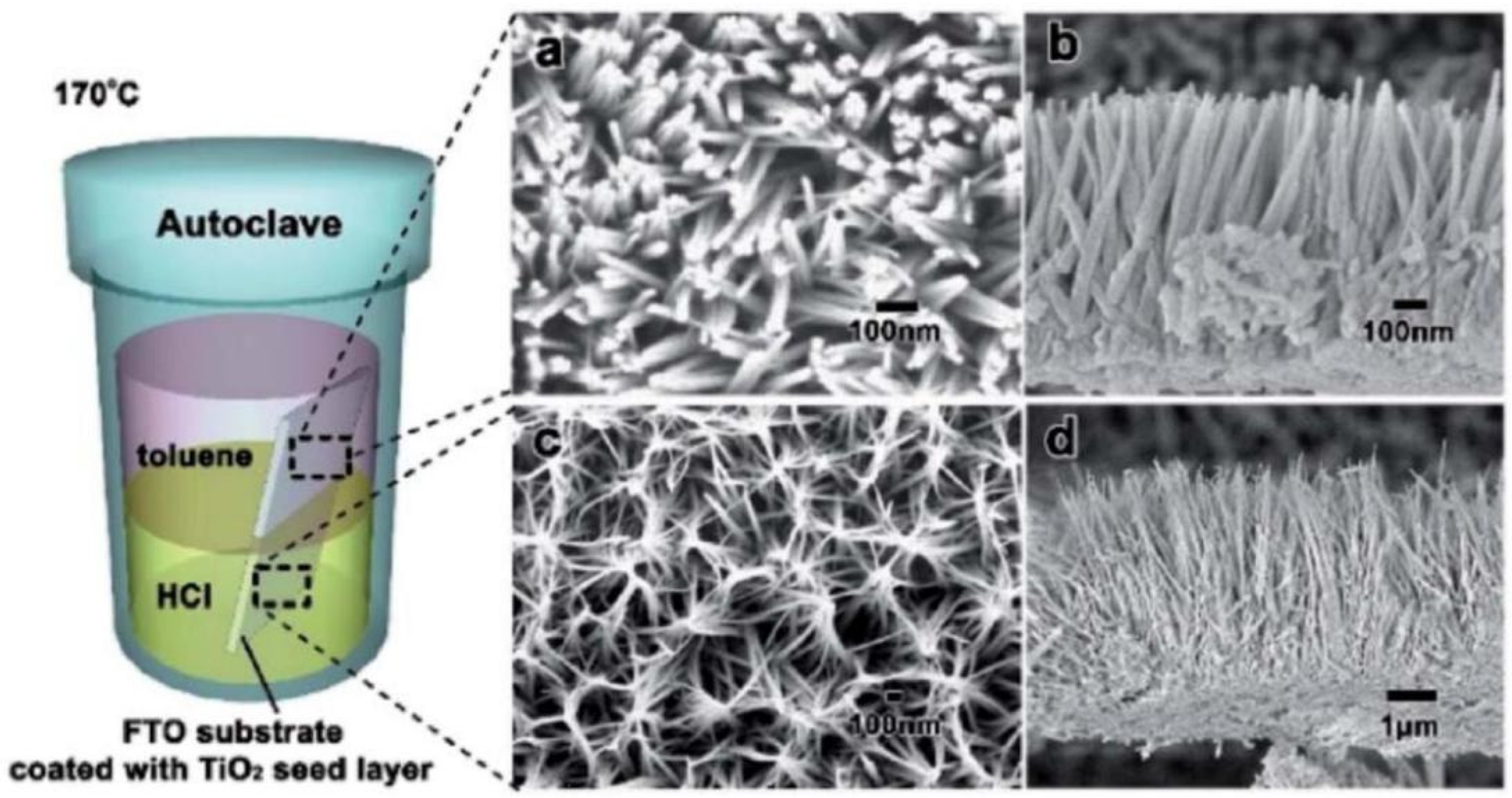

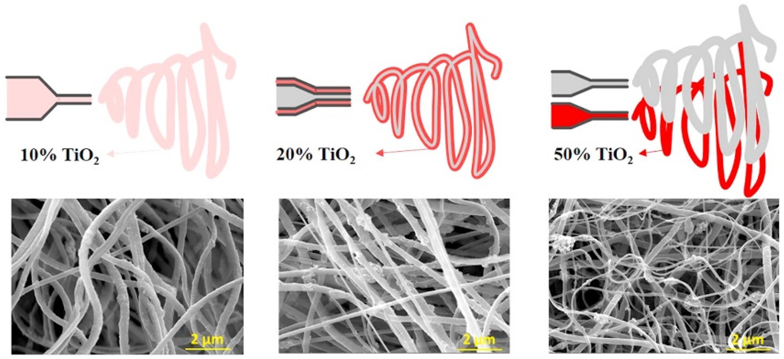
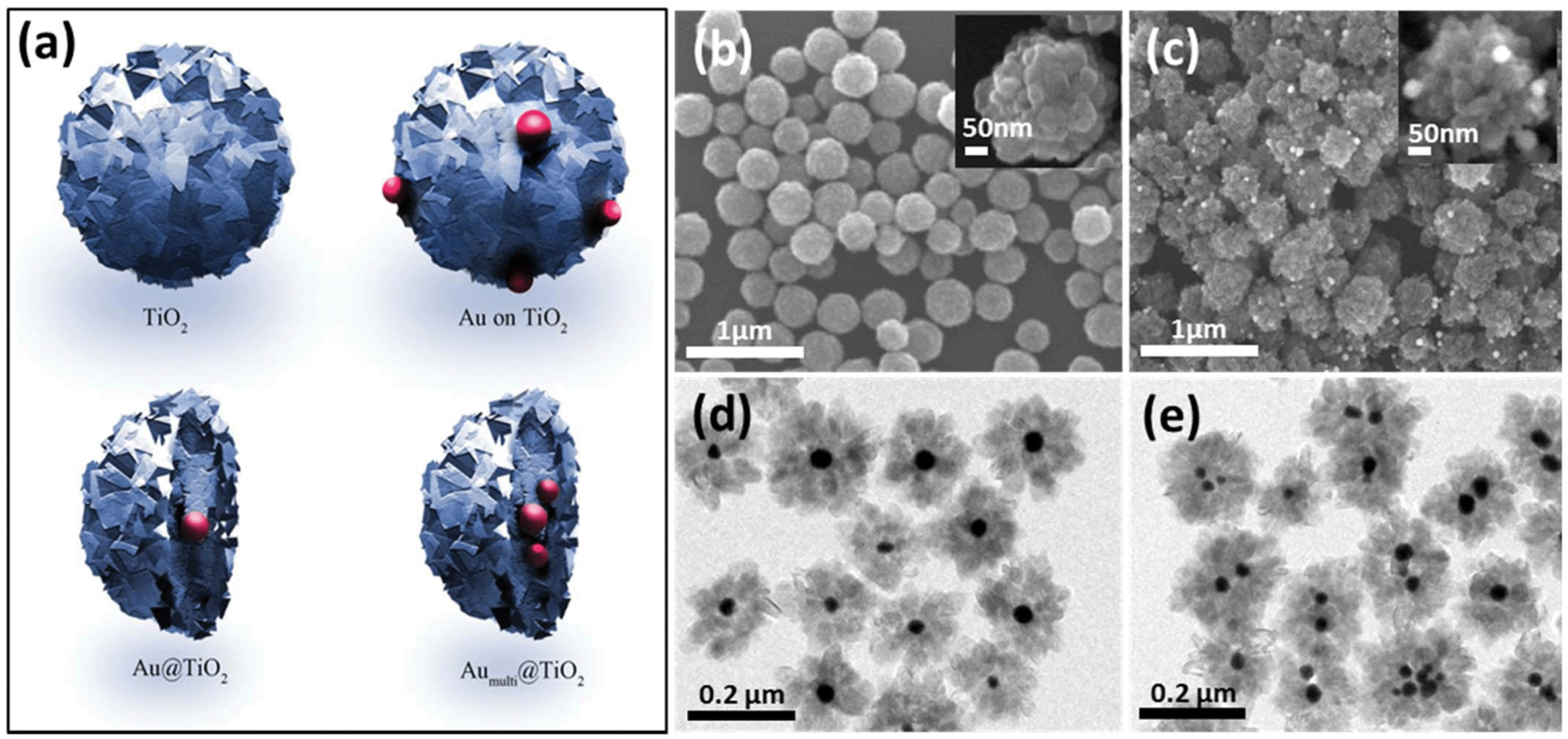


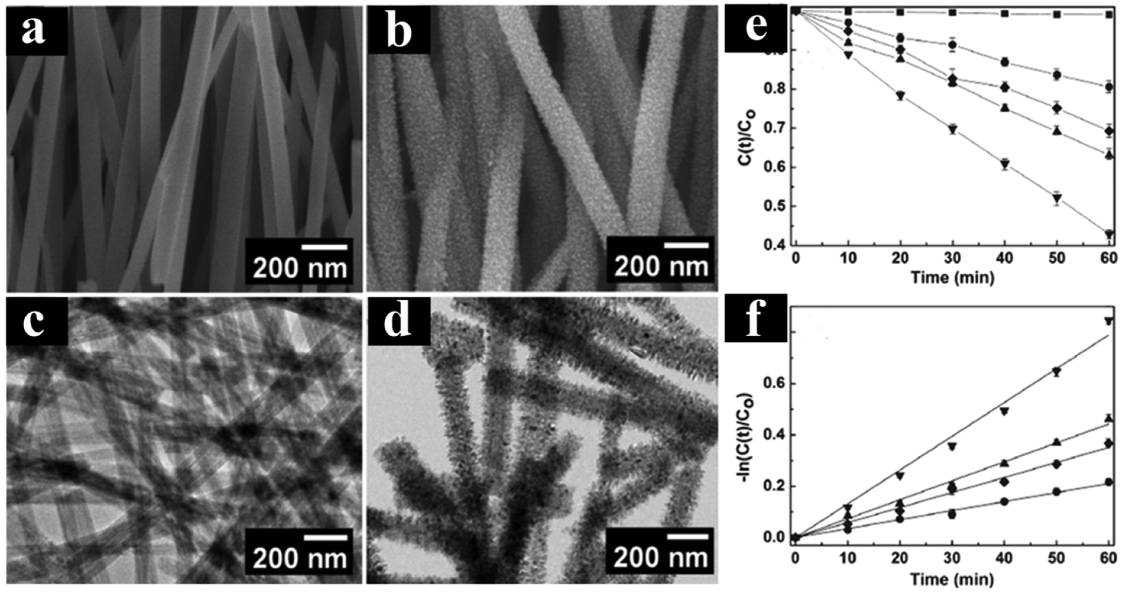
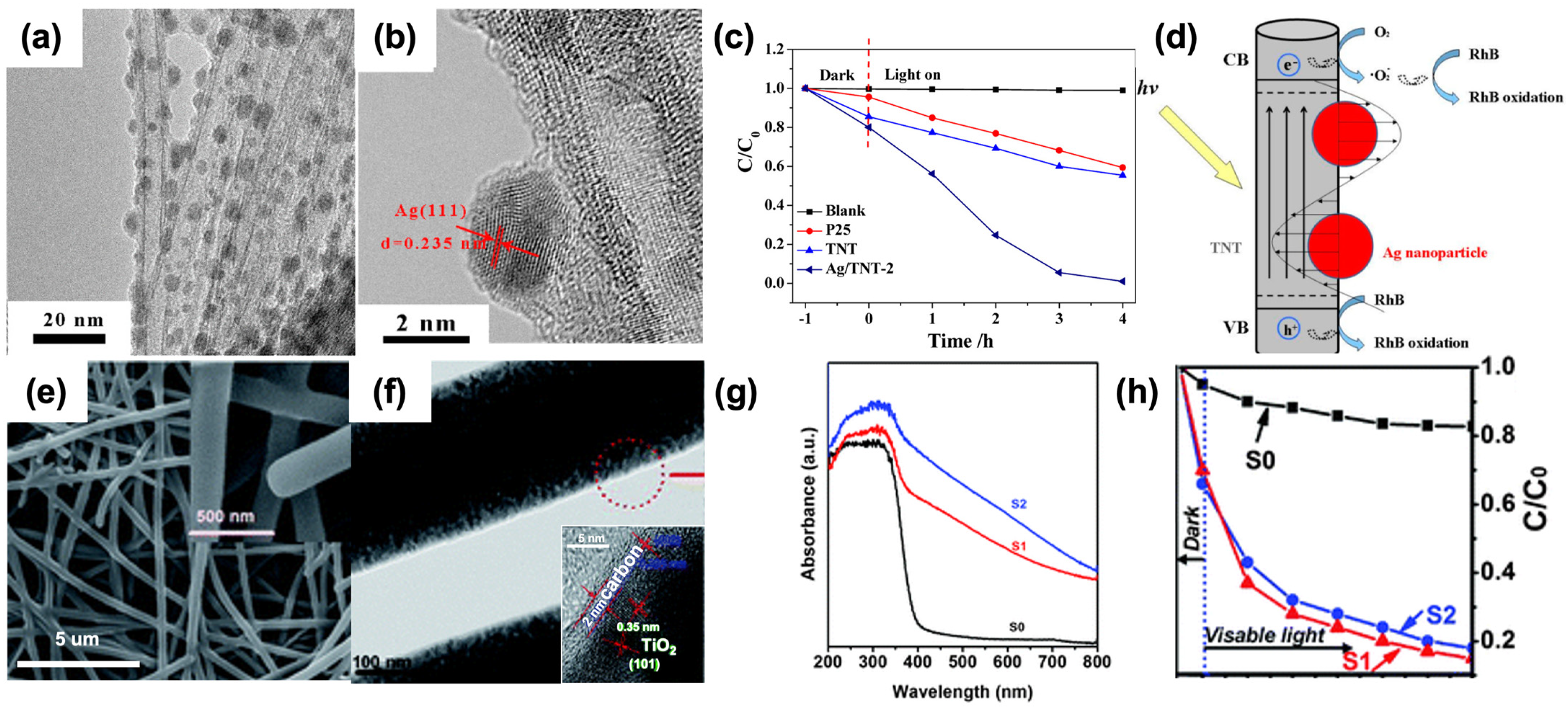
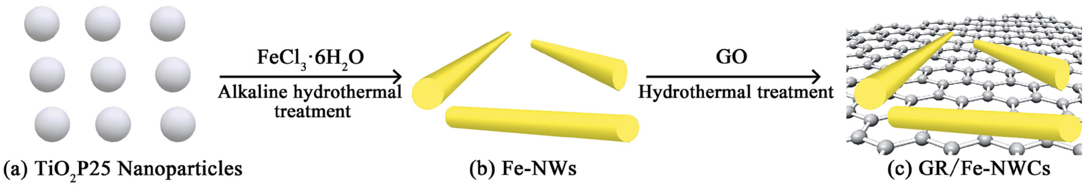
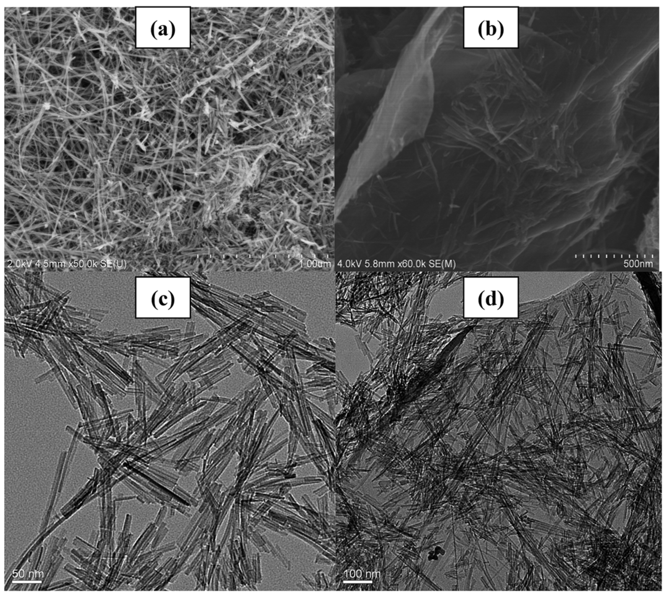
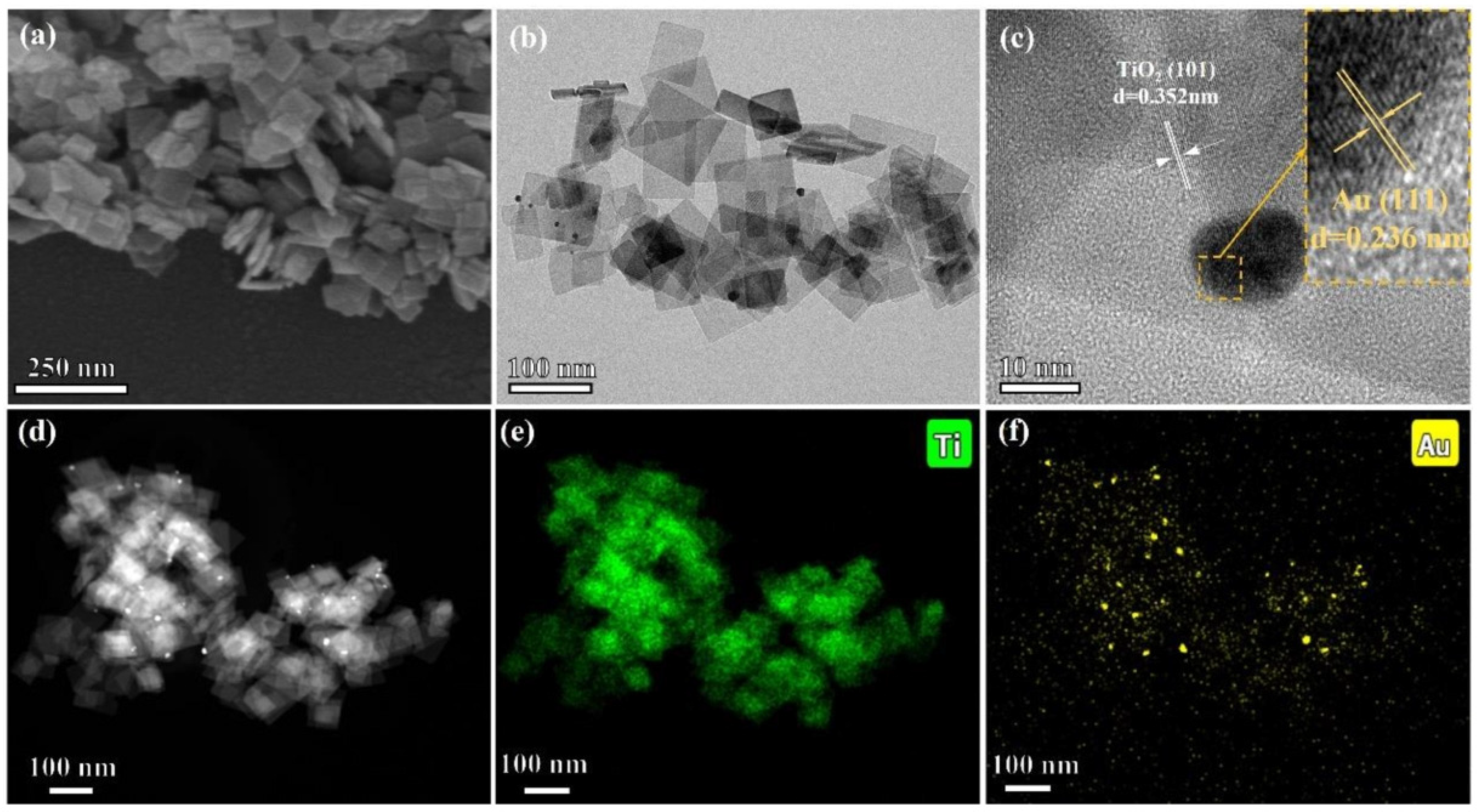
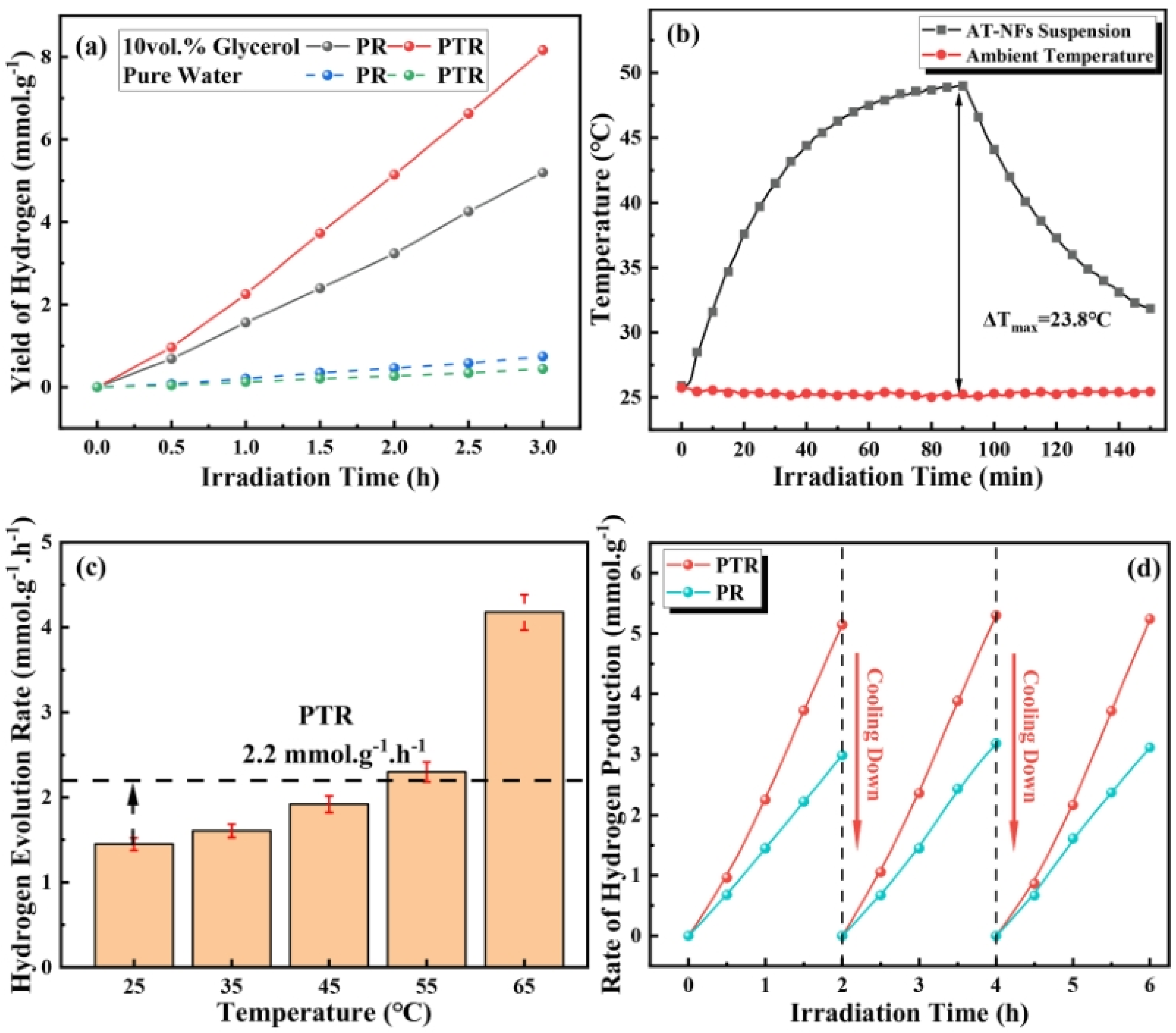
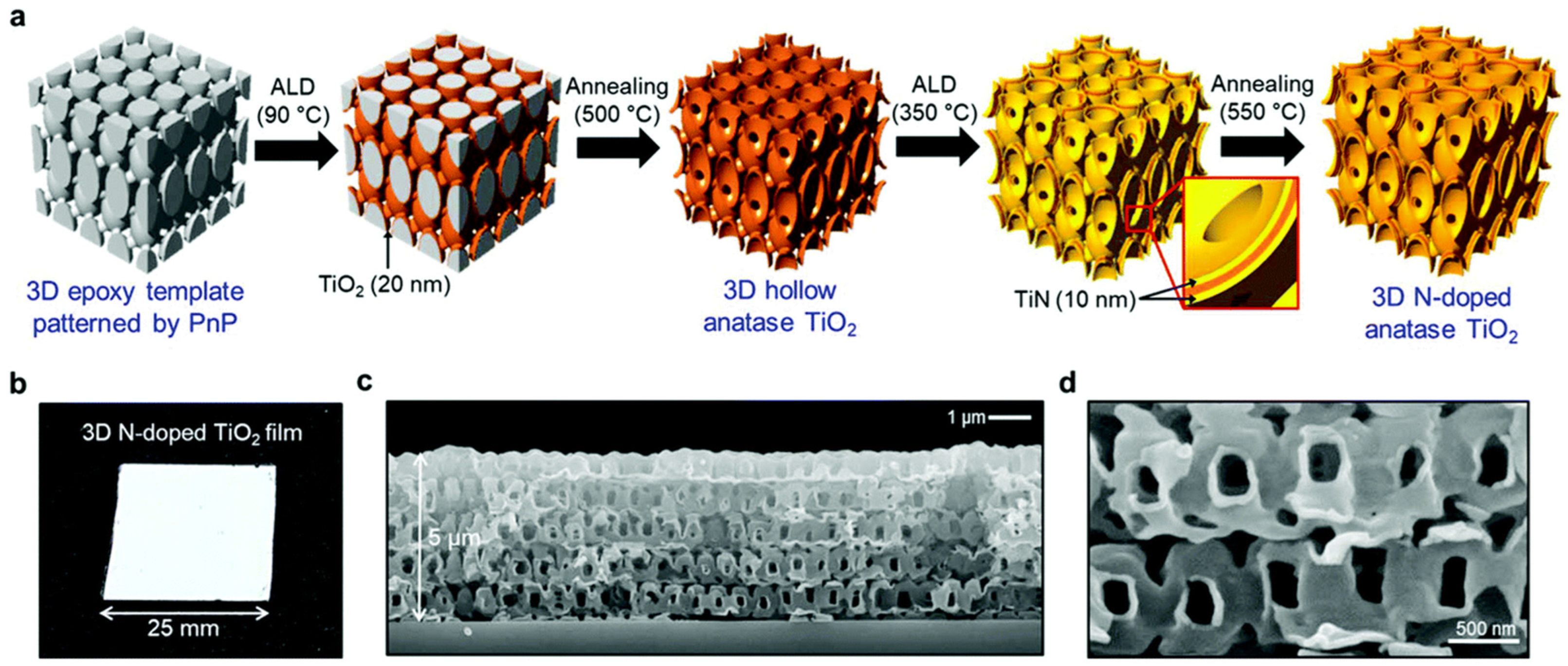
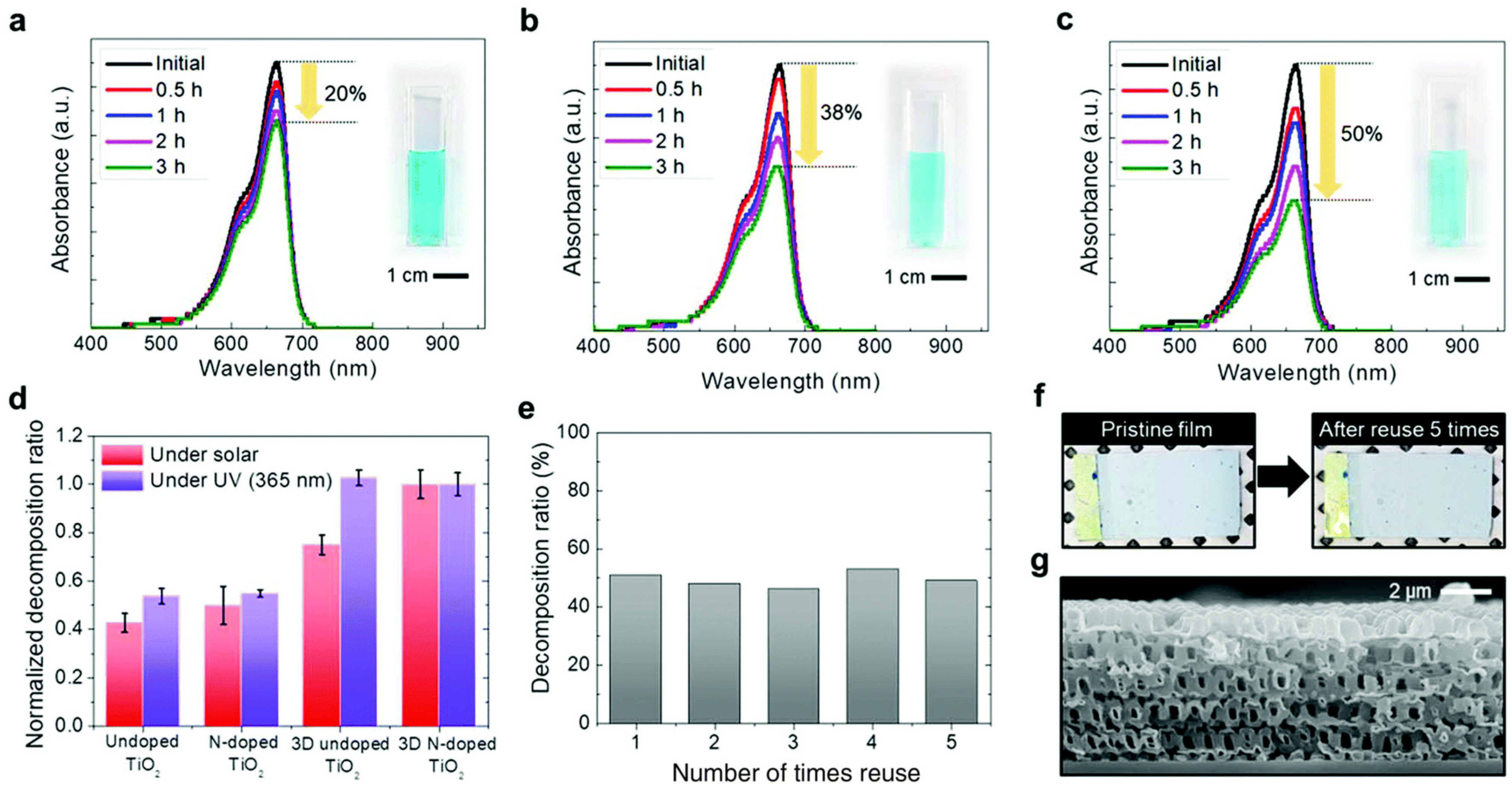
Disclaimer/Publisher’s Note: The statements, opinions and data contained in all publications are solely those of the individual author(s) and contributor(s) and not of MDPI and/or the editor(s). MDPI and/or the editor(s) disclaim responsibility for any injury to people or property resulting from any ideas, methods, instructions or products referred to in the content. |
© 2024 by the authors. Licensee MDPI, Basel, Switzerland. This article is an open access article distributed under the terms and conditions of the Creative Commons Attribution (CC BY) license (https://creativecommons.org/licenses/by/4.0/).