Article

Catalytic Decontamination of Carbon Monoxide Using Strong Metal–Support Interactions on TiO2 Microparticles

The Shmunis School of Biomedicine and Cancer Research, George S. Wise Faculty of Life Sciences, Tel Aviv University, Ramat Aviv 69978, Israel
*
Author to whom correspondence should be addressed.
These authors contributed equally to this work.
Catalysts 2024, 14(9), 622; https://doi.org/10.3390/catal14090622 (registering DOI)
Submission received: 7 July 2024 / Revised: 5 September 2024 / Accepted: 6 September 2024 / Published: 15 September 2024
(This article belongs to the Special Issue Catalytic CO Oxidation and Preferential CO Oxidation (PROX) II)

Abstract

:
The traditional catalytic oxidation of carbon monoxide (CO) using metal oxide catalysts often requires either high temperatures (thermocatalysis) or ultraviolet light (UV) excitation (photocatalysis), limiting practical applications under ambient conditions. Our research aimed to develop a catalytic system capable of oxidizing CO to CO2 at room temperature and in the dark. Using the Strong Metal–Support Interaction (SMSI) methodology, several titanium oxide (TiO2)-complexed metals were prepared (Ag, Au, Pd, and Pt). The highest catalytic efficiency of CO oxidation at room temperature was demonstrated for the TiO2-Pt complex. Therefore, this complex was further examined structurally and functionally. Two modes of operation were addressed. The first involved applying the catalytic system to remove CO from an individual’s environment (environmental system), while the second involved the installation of the catalysis chamber as a part of a personal protection unit (e.g., a mask). The catalytic activity exhibited a significant reduction in CO levels in both the environmental and personal protection scenarios. The practical application of the system was demonstrated through efficient CO oxidation in air emitted from a controlled fire experiment conducted in collaboration with the Israel Fire and Rescue Authority.

1. Introduction

During fire-associated activities in fresh-air-restricted environments, such as military operations, firefighting, and mining, a significant number of pollutants are released, including carbon monoxide (CO), sulfur derivatives (SOx), nitrogen oxides (NOx), hydrochloric acid (HCl), and hydrogen cyanide (HCN). Among those, CO is the most prevalent and dangerous. This colorless, odorless, and tasteless gas is produced due to the incomplete combustion of hydrocarbon compounds and poses severe health risks. The primary danger of CO exposure is its interaction with hemoglobin and the formation of carboxyhemoglobin (COHb) in the blood, which impairs oxygen absorption in the lungs and its transfer to cells and tissues. Furthermore, the partial occupancy of Hb by CO leads to an increased affinity of oxygen to the remaining CO-free binding sites in the tetrameric structure of Hb, resulting in diminished oxygen release to tissues (Haldane effect) [1,2]. These effects cause impaired oxygen transfer to bodily tissues, leading to hypoxia. In addition to COHb generation, CO interacts with tissue metalloproteins (e.g., myoglobin) and enzymes (e.g., peroxidases cytochromes and mitochondrial oxygenases) [3,4,5], an interaction that may lead to long-term damage to high-oxygen-demanding organs such as the lung, liver, kidney, and brain, and affect cellular respiration via the electron transport chain. These effects may lead to increased rates of heart attack, lung malfunction, and stroke, as demonstrated among firefighters upon long-term exposure to fire-generated CO [6].
This paper summarizes the research that enabled us to develop a catalytic system capable of oxidizing CO to CO2 at room temperature and in the dark without requiring light excitation.
Titanium dioxide (TiO₂), particularly in the form of nano- and microparticles, is widely used as an efficient photocatalyst. Its large band gap (approximately 3.2 eV for the anatase phase and 3.0 eV for the rutile phase) limits photocatalytic activity to the UV region in the ultraviolet (UV) range (λ < 385 nm). Upon UV illumination, excited TiO2 produces Reactive Oxygen Species (ROS) [7], which play an important role in the photocatalytic reaction mechanism [8]. Due to its photocatalytic activity, TiO2 has been widely applied in decontamination processes, particularly in self-cleaning, odor removal, the degradation of toxic materials, and bacteria annihilation [9,10]. We recently applied ROS, generated by UV-excited TiO2, for the disintegration of the nerve gas Agent X Surrogate Profenofos [11] and the clinical destruction of melanoma cells [12]. TiO2 is particularly suitable for this purpose due to its high photo-reactivity, high chemical and physical stability, low toxicity, and commercial availability at a relatively low cost comparable to other photocatalytic metal oxides [10]. Either introducing impurities on the TiO2 surface [8] or the absorption (doping) of matrix metal ions [11,13] could overcome the need for UV irradiation for catalyst activation. Metal-associated oxide catalysis has been used for decades for the oxidation of CO into CO2; however, this process often requires a high temperature, about 400 °C (e.g., in car catalytic converters [14,15]).
The term “Strong Metal–Support Interaction” was coined in the early eighties for a transition metal (of group VII) coupled to metal oxide nano- or microparticles, forming an encapsulating layer that readily reacts with the substrate [16,17]. These metals are widely used in surface activation primarily due to their high dissociation probability and very low adsorption energy [18]. Due to the strong interactions of the metal with the support, catalytic activity, selectivity, and specificity may be modulated [19,20]. The SMSI system often enables low-temperature CO oxidation [21]. The SMSI mechanism and its applications have been described in several recent reviews (e.g., [22,23,24]).
Our research aimed to develop a catalytic system capable of oxidizing CO to CO2 at room temperature and in the dark without requiring light excitation. This system was designed to utilize efficient catalysts based on TiO2, to which atoms of various metals (Ag, Au, Pd, and Pt) were attached.
In this article, we address two aspects of CO removal. One involves using the catalytic system to remove CO from an individual environment (environmental system), and the second is the installation of the catalysis chamber in a personal protection unit (e.g., a mask).

2. Results

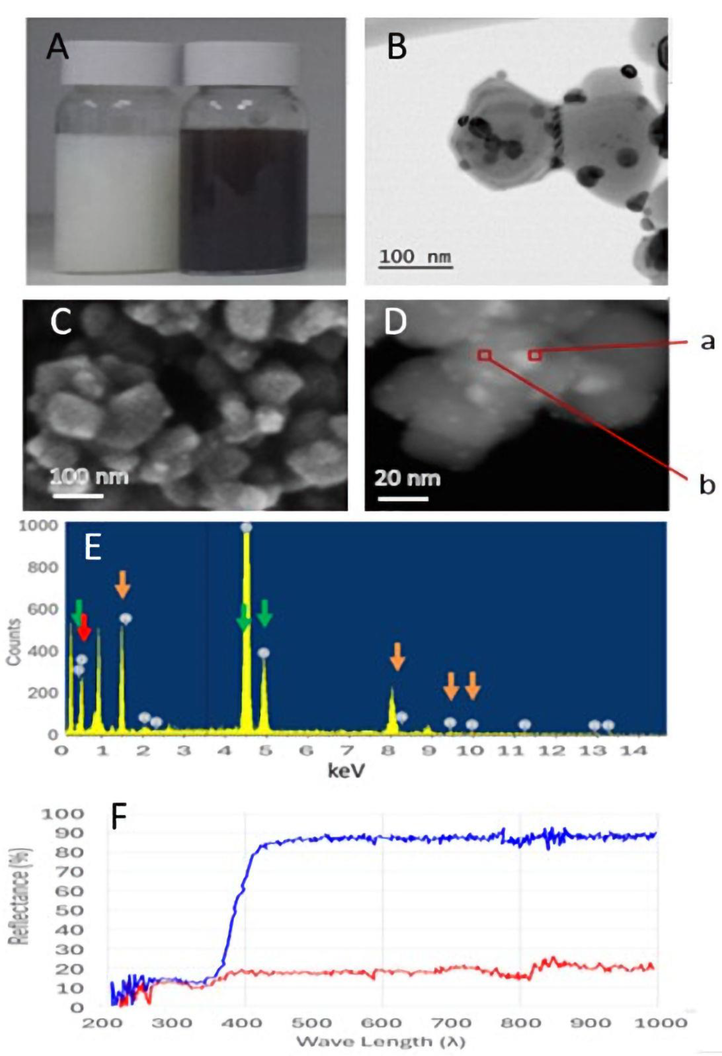
2.1. Structural Properties of TiO2-Pt Microparticles

In this study, we prepared four metal-supported catalysts—Au-, Ag-, Pd-, and Pt-based TiO2 microparticles—via the SMSI methodology [16,17]. Even though smaller particles are often considered to be a better matrix for catalysis, due to their larger surface area [25,26], we chose to concentrate on micro- rather than nanoparticles to avoid the spillage of particles through the micronic filters of the reactor cell. The catalytic efficiencies of the various metal-catalysts for CO oxidation are shown in Table 1. The most efficient was TiO2-Pt, the structural characteristics of which are shown in Figure 1. The visual appearance of TiO2 and TiO2-Pt is shown in Figure 1A The microscopic structure of the TiO2-Pt microparticle surface, determined High-Resolution Scanning Electron Microscopy (HR-SEM) is shown in Figure 1C Transmission Electron Microscopy (TE, Figure 1B) revealed metal clusters on the TiO2 surface. Similar clusters were identified by enlargement of the HR-SEM micrograph (Figure 1D). The Energy-Dispersive Spectroscopy (EDS) analysis of these clusters (point “a” in Figure 1D) identified Ti, O, and Pt in the spectrum (Figure 1E). In contrast, the Pt peak was not identified in point “b”. Finally, a reflectance spectrum (Figure 1F) reflects the difference in color of the suspensions.
The TiO2 microparticles, composed of clusters of nanoparticles (Figure 1C), were found to be mechanically stable, as they did not disintegrate in the reactor cell during operation (no leakage was observed through the 1 µm filters of the reactor cell).
The TiO2-Pt preparation contained a total of 1.03% Pt, as determined by Inductively Coupled Plasma (ICP). The surface analysis of the microparticles by EDS revealed a higher value of 1.85%. As Pt is adsorbed on the oxide surface, its percentage on the surface is expected to be higher. Similarly, the ICP measurements of TiO2-Pd, TiO2-Ag, and TiO2-Au yielded 0.7%, 2.73%, and 1.50%, respectively. The EDS results were 1.50%, 5.55%, and 3.0, respectively.

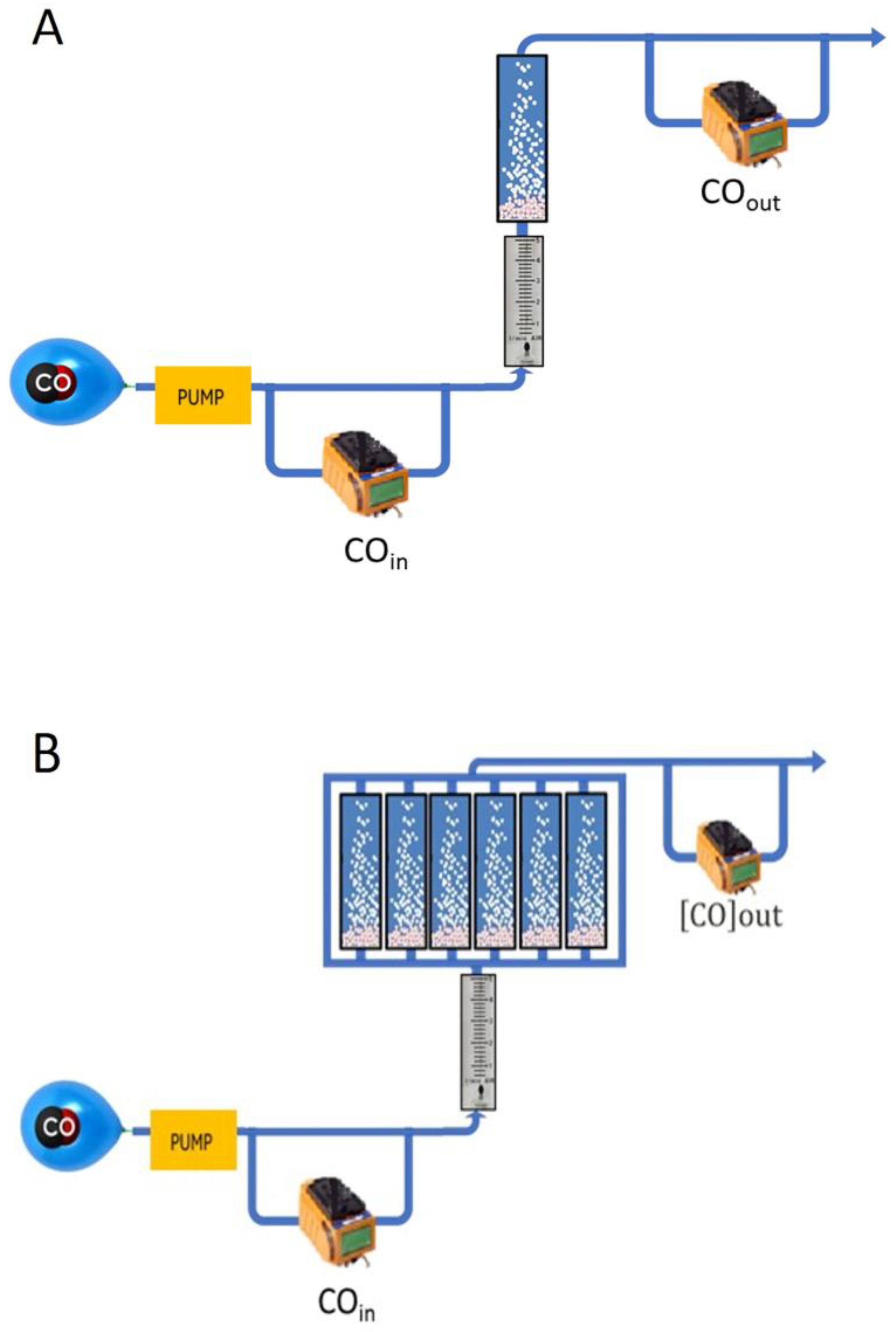
2.2. Modes of Operation

As mentioned above, the purpose of this research was to prepare a CO oxidative catalytic device and exhibit its performance in two models: one involved the removal of CO from a CO-polluted closed environment (the environmental model), while the other concerned its application for personal protection (the mask model).

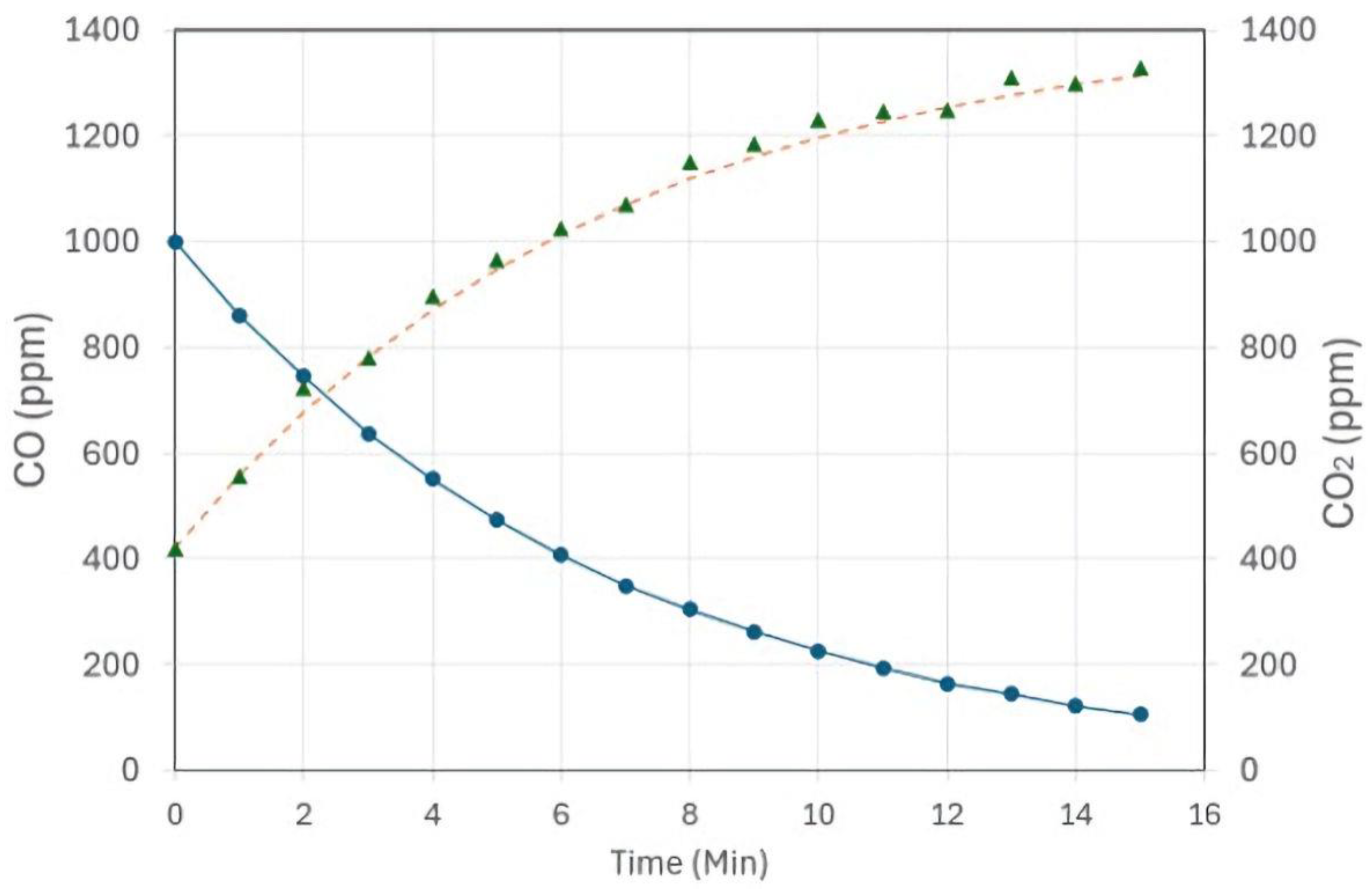
2.2.1. The Environmental Model
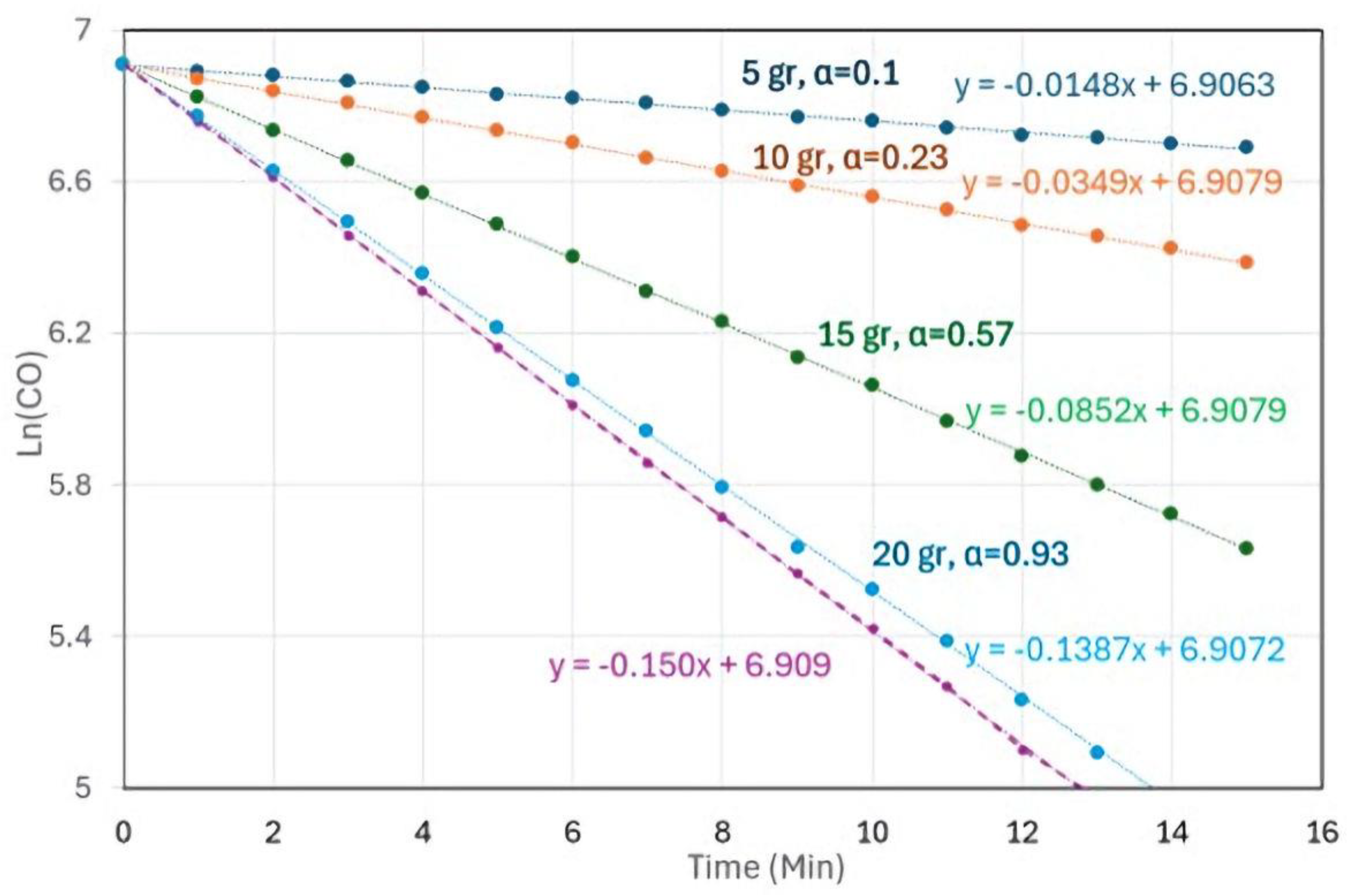
The environmental model (Figure 2) consisted of a 20 L container filled with air containing CO at a certain concentration (usually 400–1000 ppm). A closed flow system circulates the CO-containing air through a reaction cell, where CO levels are continuously monitored. At a certain amount of catalyst and under certain conditions, the catalytic oxidation of CO was expected to be a first-order reaction:
d[CO]/dt = −k[CO],
[CO]t = [CO]0+ e−kt,
Ln([CO]t/[CO]0) = −kt
t1/2 = ln2/k.
k was calculated as k = F/V+α, where F, V, and α are the flow rate, container volume, and catalytic efficiency, respectively. [CO]0 and [CO]t are CO concentrations (in ppm) at times 0 and t, respectively. The maximum value of k (kmax, where α = 1) was obtained by letting fresh air flow into the container through the exit of the reactor (point X in Figure 2A). Thus, α equals k/kmax.
The first-order kinetics of the catalytic reaction are demonstrated in Figure 3, where the catalytic efficiency (α) is shown as a function of the catalyst mass in the range of up to 20 g, an amount that yielded α = 1. At higher masses, α remained at 1. This experiment was carried out at a flow rate of 3 L/min. At a lower flow rate, a lower amount of catalyst would be sufficient to reach a maximal catalytic efficiency (e.g., 12.8 g at 1.8 L/min, in Table 2).
Table 1. The catalytic efficiencies (α) of the various metal oxides tested, as well as t1/2 values (Equation (4)). Amounts of 15 g of each catalyst were inserted into the reaction cell (diameter = 4 cm, height = 3.5 cm). The volume of the container was 20 L and the flow rate was 3 L/min. * value of kmax is taken from Figure 3.
k (1/min)αt1/2 (min)
TiO20.0000.000
Max *0.1501.0004.6
TiO2-Ag0.0010.007693.1
TiO2-Au0.0010.007693.1
TiO2-Pd0.0270.18025.7
TiO2-Pt0.0850.5678.2
Figure 3. The catalytic activity and the efficiencies (α) at various amounts of TiO2-Pt in the reactor. The reactor was operated at a flow rate of 3 L per minute at room temperature.
Catalysts 14 00622 g003
To confirm that the reaction product was CO2, the gas was measured during the reaction time. As shown in Figure 4, an increase in CO2 concentration in the container was observed parallel to the decrease in CO, following the expected equation:
[CO2]t = [CO2]0 + [CO]0 ˖(1 − e−kt), k = 0.085.

2.2.2. The Linear (Personal) Model

The purpose of the linear model was to simulate a mask device that enables breathing clean air in a polluted space. This system (Figure 5A) is based on a single pass of CO from a reservoir through the reactor. The catalytic efficiency is defined as follows:
α = 1 − COout/COin
COin and COout are the CO concentrations (in ppm) at the entrance and the exit from the reactor cell, respectively.
As shown in Table 2, as the flow rate in the reactor is increased, there is a limit above which α becomes less than one (FRmax). As the amount of TiO2-Pt in the reactor increases, FRmax increases as well. This value determines the minimal residence time in the reactor that is required for the complete oxidation of CO (Table 3). The higher the value of FRmax, the shorter the residence time required for CO to undergo complete oxidation and the higher the catalyst’s activity. As shown in Table 3, the specific activity remained practically constant regardless of the amount of the catalyst in the reactor cell (5.7 ± 0.4 µmol CO/g catalyst/min).

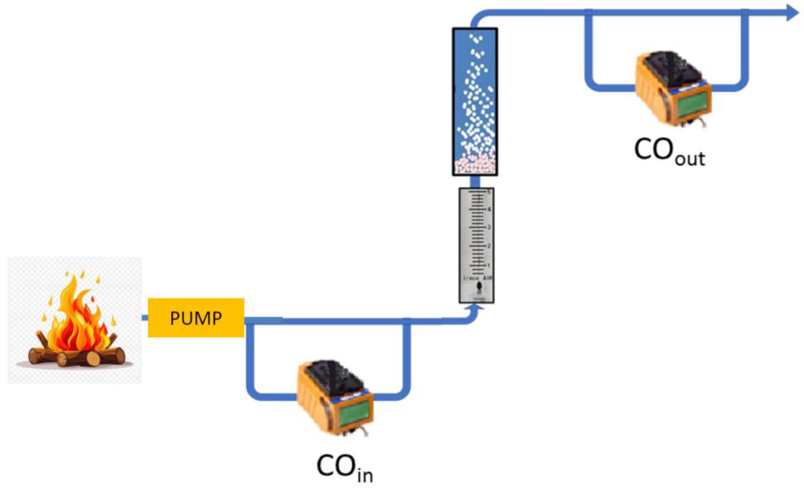
2.2.3. Case Study of Neutralizing CO Produced by a Fire

This experiment was carried out in collaboration with the Israel Fire and Rescue Authority. A fire was initiated within a sealed room (3 × 3 × 2.5 m3). Air was sampled into the reactor cell via a stainless tubing passing through a hole in the room wall (Figure 6). COin and COout were measured and α was determined. As shown in Table 4, α values ranged from 0.98 to 0.99 until the fire was extinguished.

3. Discussion

CO is the most significant pollutant produced during the incomplete combustion of carbonaceous compounds. The introduction of SMSI, a fast-growing area in catalysis research, enabled efficient CO oxidation to CO2 at low temperatures. Unlike photocatalysis by TiO2, which requires activation of the oxide at the UV range to produce Reactive Oxygen Species (ROS), the SMSI methodology is based on the adsorption of CO on metal clusters, which leads to changes in the electronic properties, surface structure, and catalytic activity of the metal. In parallel, O2 is absorbed on the TiO2 support, resulting in ROS formation due to the electron transfer between Pt and TiO2. Finally, CO reacts with the activated oxygen to form CO2, which is desorbed [17,24,27,28].
The SMSI methodology was used to prepare four catalysts that were based on the interactions of Ag+1, Au+2, Pd+2, and Pt+4 with TIO2 microparticles. We chose to use TiO2 microparticles rather than nanoparticles to avoid the spillage of particles through the 1 µm filters of the reactor cell. Despite the higher metal percentage on the surface of TiO2-Ag and TiO2-Au, they showed the lowest activity of the four preparations, while TiO2-Pt possessed the highest catalytic efficiency (Table 1). Therefore, we decided to concentrate on this catalyst.
Two models were investigated: one involved the removal of CO from a CO-polluted closed environment (the environmental model), and the other concerned an application for personal protection (the mask model). We have shown that TiO2-Pt is efficient in CO removal. The catalytic efficiency increased with catalyst mass but was limited by the flow rate, as CO oxidation required a minimal residence time (Table 3) of the gas in the reactor. To enable a higher flow rate through the system, several reactors were used in parallel, as described in Figure 5B.
The catalytic efficiency of TiO2-Pt depended on both a minimal residence time of CO in the reactor cell (an inverse function of flow rate) and the mass of the catalyst in the reactor cell. The higher the catalyst mass, the lower the residence time that was required for maximal catalytic efficiency. Thus, the catalytic activity increased with an increased catalyst mass, while the specific activity remained constant. This finding suggests that specific activity is an intrinsic property of the TiO2-Pt preparation.
The in-situ removal of CO using SMSI catalysts supported by TiO2 holds significant promise for addressing environmental and safety concerns in various scenarios, particularly during activities like firefighting, military operations, mining, etc., where CO exposure is common. TiO2, as a support material for metal catalysts, offers a synergistic approach to combat CO pollution efficiently. This model was shown, in collaboration with the Israel Fire and Rescue Authority, to neutralize CO emitted from an initiated fire. Such positive results may lead to the adoption of this system by fire authorities all over the world.
In conclusion, the development and utilization of metal catalysts supported on TiO2 for the in-situ removal of carbon monoxide represents a promising approach to mitigating the harmful effects of CO exposure. By leveraging the synergistic effects of TiO2’s catalytic properties and the catalytic activity of metal species, this technology has the potential to enhance safety, protect individuals from CO hazards, and contribute to a cleaner and healthier environment.

4. Materials and Methods

4.1. Materials

All chemicals and carriers were of analytical grade and purchased from Merck (Rahway, NJ, USA), unless otherwise specified. TiO2 anatase microparticles (10 µm) were purchased from Titan-Shield (Welling, UK).

4.2. Methods

4.2.1. Catalyst Preparation

TiO2-Pt

The catalysts described in this work are Supported-Metal Catalysts [16,17], and were prepared as described by Li et al. [29]. In short, micrometric anatase TiO2 particles (10 g in 1 L of ionized water) were sonicated at maximal power (100 kHz) for 5 min at 50 °C. Hexachloroplatinate(iv)hydrate (3.75 mL of a 400 mM solution) was added, and the solution was stirred for 30 min at pH = 7. Then, the pH was adjusted to pH 10 with NH4OH and the solution was then reduced with NaBH4 (0.473 g). After stirring for 30 min, the precipitate was collected and dried at 100 °C overnight.
This procedure was repeated five times, and the solid samples were dried overnight at 50 °C in a dry oven.

TiO2-Ag, TiO2-Au, and TiO2-Pd

These metal-oxide derivatives were synthesized as described in the paragraph on TiO2-Pt, except that AgNO3, AuCl2, and PdCl2 (10 g, each) were used as the original salts.

4.2.2. TiO2-Pt Characterization

HRSEM and EDS Analyses

This analysis was performed using HRSEM (Zeiss Ultra-Plus FEG HR-SEM) with EDX (energy-dispersive X-ray), SE (secondary electron), and back-scattered electron (BSE) detectors. The powdered sample was dispersed in ethanol and the suspension was sonicated (100 kHz) for 3 min at room temperature. The suspension was applied as a droplet on an adhesive C slice without additional coating.

TEM Analysis

TEM micrographs were obtained using a JEOL JEM 2100 at 200 kV in TEM and STEM mode. The sample was dispersed in ethanol and the suspension was sonicated (100 kHz) for 30 min at room temperature. The suspension was applied as a droplet on a copper grid without additional coating.

ICP Analysis

ICP analysis was carried out as described in [30]. In short, 15 mL of concentrated nitric acid (HNO3) was added to 0.5 g samples of TiO2–metal complexes were dispersed in an ultrasonic bath at room temperature for 30 min and then heated in a heating block for two hours at 150 °C. After cooling, the solution was diluted with distilled water. Samples of 5 mL were injected into the ICP spectrometer.

Reflectance Spectrum

Reflectance spectra were recorded in diffuse reflectance mode (R) using a Thermo Scientific Evolution 300 spectrometer equipped with a DRA-EV-300 Integrating Sphere with BaSO4 as the standard.

4.2.3. CO and CO2 Measurements

CO and CO2 concentrations were monitored using a Gas-Pro CO detector (Crowcon Detection Instruments Ltd., Abingdon, UK) equipped with the appropriate cells. The detectors were serially connected (1 Hz sampling rate) to a data logger.

4.2.4. Calculation of Catalytic Activity

The catalytic activity in µmol/min was calculated as follows:
Activity = α˖CO0(ppm)˖Flow rate (L/min)/24.4.
The catalytic specific activity was calculated as the catalytic activity divided by catalyst mass (in g).

5. Conclusions

In this study, several catalysts were prepared based on metal absorption to TiO2-Pt using the SMSI methodology. Out of the metals examined (Ag, Au, Pd, and Pt), TiO2-Pt proved to be highly effective in catalyzing CO oxidation to CO2. In our investigations, TiO2 microparticles, rather than nanoparticles, were used to prevent particle leakage through the 1 µm reactor filters. Two models were examined: one focused on the ability of the system to remove CO from a contaminated environment (the environmental model) and the other examined CO removal in a personal protection unit. The catalytic efficiency of TiO2-Pt depended on both the residence time of CO in the reactor cell (an inverse function of the flow rate) and the catalyst mass. The higher the catalyst mass, the lower the residence time required for maximal catalytic efficiency. The effectivity of the TiO2-Pt catalyst was validated in a controlled fire experiment conducted in collaboration with the Israel Fire and Rescue Authority.

Author Contributions

Conceptualization, J.A. and G.F.; methodology, A.D., J.A. and G.F.; Investigation A.D., J.A. and G.F.; writing—original draft preparation, A.D., J.A. and G.F.; writing—review and editing, A.D., J.A. and G.F.; supervision, G.F.; project administration, G.F.; funding acquisition, G.F. All authors have read and agreed to the published version of the manuscript.

Funding

This research was funded by the Research Fund of the IDF Medical Corpus (Project: 00340051000).

Data Availability Statement

All data can be accessed by correspondence with GF.

Acknowledgments

The authors wish to express their gratitude to Ronit Hollander from Studio Hollander for her graphical assistance.

Conflicts of Interest

The authors declare no conflicts of interest.

References

  1. Ryter, S.W.; Otterbein, L.E. Carbon monoxide in biology and medicine. Bioessays 2004, 26, 270–280. [Google Scholar] [CrossRef] [PubMed]
  2. Roughton, F.; Darling, R. The effect of carbon monoxide on the oxyhemoglobin dissociation curve. Am. J. Physiol.-Leg. Content 1944, 141, 17–31. [Google Scholar] [CrossRef]
  3. Sangalli, B.; Bidanset, J. A review of carboxymyoglobin formation: A major mechanism of carbon monoxide toxicity. Vet. Hum. Toxicol. 1990, 32, 449–453. [Google Scholar] [PubMed]
  4. Piantadosi, C.A. Biological chemistry of carbon monoxide. Antioxid. Redox Signal. 2002, 4, 259–270. [Google Scholar] [CrossRef]
  5. Coburn, R.F. Mechanisms of carbon monoxide toxicity. Prev. Med. 1979, 8, 310–322. [Google Scholar] [CrossRef]
  6. Burgess, J.L.; Brodkin, C.A.; Daniell, W.E.; Pappas, G.P.; Keifer, M.C.; Stover, B.D.; Edland, S.D.; Barnhart, S. Longitudinal decline in measured firefighter single-breath diffusing capacity of carbon monoxide values: A respiratory surveillance dilemma. Am. J. Respir. Crit. Care Med. 1999, 159, 119–124. [Google Scholar] [CrossRef]
  7. Fujishima, A.; Honda, K. Electrochemical photolysis of water at a semiconductor electrode. Nature 1972, 238, 37–38. [Google Scholar] [CrossRef]
  8. Zaleska, A. Doped-TiO2: A review. Recent Pat. Eng. 2008, 2, 157–164. [Google Scholar] [CrossRef]
  9. Pelaez, M.; Falaras, P.; Likodimos, V.; Kontos, A.G.; De la Cruz, A.A.; O’shea, K.; Dionysiou, D.D. Synthesis, structural characterization and evaluation of sol–gel-based NF-TiO2 films with visible light-photoactivation for the removal of microcystin-LR. Appl. Catal. B Environ. 2010, 99, 378–387. [Google Scholar] [CrossRef]
  10. Elias, C.N.; Lima, J.H.C.; Valiev, R.; Meyers, M.A. Biomedical applications of titanium and its alloys. JOM 2008, 60, 46–49. [Google Scholar] [CrossRef]
  11. Dayan, A.; Mor Yosef, R.; Risphon, J.; Tuval, E.; Fleminger, G. In Situ Detoxification of Venomous Agent X Surrogate Profenofos by Doped Titanium Dioxide Nanoparticles under Illumination at the UV and Visible Ranges. J. Phys. Chem. A 2019, 123, 9456–9461. [Google Scholar] [CrossRef] [PubMed]
  12. Dayan, A.; Fleminger, G.; Ashur-Fabian, O. RGD-modified dihydrolipoamide dehydrogenase conjugated to titanium dioxide nanoparticles–switchable integrin-targeted photodynamic treatment of melanoma cells. RSC Adv. 2018, 8, 9112–9119. [Google Scholar] [CrossRef] [PubMed]
  13. Park, H.; Park, Y.; Kim, W.; Choi, W. Surface modification of TiO2 photocatalyst for environmental applications. J. Photochem. Photobiol. C Photochem. Rev. 2013, 15, 1–20. [Google Scholar] [CrossRef]
  14. Mukherjee, A.; Roy, K.; Bagchi, J.; Mondal, K. Catalytic converter in automobile exhaust emission. J. Res 2016, 2, 29–33. [Google Scholar]
  15. Khoiron, A.M.; Anis, S.; Masugino, S.S.M.; Fajri, S.N. Catalytic converter based on titanium oxide (TiO2) to reduce the emission of carbon monoxide and hydrocarbon in exhaust gas of motor vehicles. EIC 2020, 2018, 15–20. [Google Scholar]
  16. Tauster, S.; Fung, S. Strong metal-support interactions: Occurrence among the binary oxides of groups IIA–VB. J. Catal. 1978, 55, 29–35. [Google Scholar] [CrossRef]
  17. Tauster, S.; Fung, S.; Baker, R.; Horsley, J. Strong interactions in supported-metal catalysts. Science 1981, 211, 1121–1125. [Google Scholar] [CrossRef]
  18. Al Soubaihi, R.M.; Saoud, K.M.; Dutta, J. Critical review of low-temperature CO oxidation and hysteresis phenomenon on heterogeneous catalysts. Catalysts 2018, 8, 660. [Google Scholar] [CrossRef]
  19. van Deelen, T.W.; Hernández Mejía, C.; de Jong, K.P. Control of metal-support interactions in heterogeneous catalysts to enhance activity and selectivity. Nat. Catal. 2019, 2, 955–970. [Google Scholar] [CrossRef]
  20. Lou, Y.; Xu, J.; Zhang, Y.; Pan, C.; Dong, Y.; Zhu, Y. Metal-support interaction for heterogeneous catalysis: From nanoparticles to single atoms. Mater. Today Nano 2020, 12, 100093. [Google Scholar] [CrossRef]
  21. Kim, H.J.; Jang, M.G.; Shin, D.; Han, J.W. Design of ceria catalysts for low-temperature CO oxidation. ChemCatChem 2020, 12, 11–26. [Google Scholar] [CrossRef]
  22. Pu, T.; Zhang, W.; Zhu, M. Engineering heterogeneous catalysis with strong metal–support interactions: Characterization, theory and manipulation. Angew. Chem. Int. Ed. 2023, 62, e202212278. [Google Scholar] [CrossRef] [PubMed]
  23. Luo, Z.; Zhao, G.; Pan, H.; Sun, W. Strong metal–support interaction in heterogeneous catalysts. Adv. Energy Mater. 2022, 12, 2201395. [Google Scholar] [CrossRef]
  24. Zhang, L.; Cheng, X.; Zhang, G.; Qiu, W.; He, H.; Chen, G. High active platinum clusters on titanium dioxide supports toward carbon monoxide oxidation. Appl. Catal. B Environ. 2020, 266, 118629. [Google Scholar] [CrossRef]
  25. Li, N.; Chen, Q.-Y.; Luo, L.-F.; Huang, W.-X.; Luo, M.-F.; Hu, G.-S.; Lu, J.-Q. Kinetic study and the effect of particle size on low temperature CO oxidation over Pt/TiO2 catalysts. Appl. Catal. B Environ. 2013, 142, 523–532. [Google Scholar] [CrossRef]
  26. Bond, G.C. The origins of particle size effects in heterogeneous catalysis. Surf. Sci. 1985, 156, 966–981. [Google Scholar] [CrossRef]
  27. Green, R.; Morrall, P.; Bowker, M. CO Spillover and Oxidation on Pt/TiO2. Catal. Lett. 2004, 98, 129–133. [Google Scholar] [CrossRef]
  28. Song, J.; Yang, Y.; Liu, S.; Li, L.; Yu, N.; Fan, Y.; Chen, Z.; Kuai, L.; Geng, B. Dispersion and support dictated properties and activities of Pt/metal oxide catalysts in heterogeneous CO oxidation. Nano Res. 2021, 14, 4841–4847. [Google Scholar] [CrossRef]
  29. Li, M.; Noriega-Trevino, M.E.; Nino-Martinez, N.; Marambio-Jones, C.; Wang, J.; Damoiseaux, R.; Ruiz, F.; Hoek, E.M. Synergistic bactericidal activity of Ag-TiO2 nanoparticles in both light and dark conditions. Environ. Sci. Technol. 2011, 45, 8989–8995. [Google Scholar] [CrossRef]
  30. Shelly, S.; Zaltsman, S.L.; Ben-Gal, O.; Dayan, A.; Ganmore, I.; Shemesh, C.; Atrakchi, D.; Garra, S.; Ravid, O.; Rand, D. Potential neurotoxicity of titanium implants: Prospective, in-vivo and in-vitro study. Biomaterials 2021, 276, 121039. [Google Scholar] [CrossRef]
Figure 1. Structural characteristics of TiO2-Pt microparticles. (A)—Visual appearance of microparticle suspensions of TiO2 (left) and TiO2-Pt (right). (B)—TEM micrograph; the Pt clusters are black. (C)—HRSEM micrographs of TiO2-Pt microparticles. (D)—Enlargement of (C). The Pt clusters on the TiO2-Pt surface are white. (E)—EDS spectrum of point “a” in plate (D). The green arrows are Ti, the orange ones are Pt, and the red one is O. (F)—Reflectance spectra of TiO2 (blue) and TiO2-Pt (red) microparticles; the black TiO2-Pt microparticles fail to reflect light.
Catalysts 14 00622 g001
Figure 2. (A) Schematic illustration of the environmental model. (a) A stirred container (20 L) fed with CO at a certain concentration from a reservoir (b). The air is pumped by a flow-rate-regulated pump (c) through a flowmeter (d) into a reactor cell (e) and back into the container. The CO concentration in the container is continuously monitored by a CO detector (f). To simulate maximal catalytic efficiency (α = 1), the tubing at point X was disconnected, and fresh air was sucked into the container. (B) A detailed scheme of the reactor cell (4 cm diameter, 3.5 cm height). The bottom-to-top air flow creates a “floating bed” situation, causing a better dispersion of the particles in the reactor.
Catalysts 14 00622 g002
Figure 4. Generation of CO2 (triangles) during CO oxidation (circles) in the container.
Catalysts 14 00622 g004
Figure 5. The linear system for CO oxidation. The source for CO (blue balloon) is a 20–80 L aluminum inflatable balloon, containing CO at certain concentrations. COin and COout were monitored in parallel streams to avoid interference of the detectors’ pumps with the general flow rate. (A)—A uni-cell unit. (B)—A multi-cell unit.
Catalysts 14 00622 g005
Figure 6. Catalytic treatment of CO released by an initiated fire in a sealed room.
Catalysts 14 00622 g006
Table 2. The dependence of catalytic efficiency (α) on the air flow rate in the reactor. TiO2-Pt (12.8 g) microparticles were placed in the reactor cell, which was operated at various flow rates. The maximal flow rate that still yielded α = 1 (FRmax) is marked Bold.
Flow Rate (L/min)COin (ppm)COout (ppm)α
1.01370<100.99
1.21804<100.99
1.51610<100.99
1.81624100.99
2.01634910.94
3.017208560.55
Table 3. Values of maximal flow rates (FRmax) at different loads of catalyst and the residence time of CO in the reactor cell, calculated as cell volume (40 mL)/flow rate (mL/s). The activity (µmol CO/min) was calculated as α˖CO0(ppm)˖Flow rate (L/min)/24.4 (24.4 L is the volume of 1 mol of gas at 298oK, CO0 was 1000 ppm). The specific activity is the activity per g of the catalyst.
Mass
(g)
FRmax
(L/min)
Residence Time
(s)
Activity
(µmol/min)
Sp. Activity
(µmol/g/min)
12.81.81.3373.85.76
20.03.00.80123.06.15
30.03.70.65151.65.05
42.86.00.40245.95.75
50.07.00.34286.95.74
Table 4. The catalytic efficiency α, of the reactor acting on CO-containing air sampled from a confined room in which a fire was set. The cell size was 44 mL, the catalyst mass was 20 g, and the sampling flow rate was 2.5 L/min.
T (min)COin (ppm)COout (ppm)α
19630.97
22450.79
320150.98
421450.98
547450.99
646450.99
736390.98
8100770.99
977090.99
1098980.99
117950.94
122030.85
Disclaimer/Publisher’s Note: The statements, opinions and data contained in all publications are solely those of the individual author(s) and contributor(s) and not of MDPI and/or the editor(s). MDPI and/or the editor(s) disclaim responsibility for any injury to people or property resulting from any ideas, methods, instructions or products referred to in the content.

