Article

Influence of Current Collector Design and Combination on the Performance of Passive Direct Methanol Fuel Cells

by
Weibin Yu
1,
Zhiyuan Xiao
1,
Weiqi Zhang
1,
Qiang Ma
1,
Zhuo Li
1,
Xiaohui Yan
2,
Huaneng Su
1,
Lei Xing
3,* and
Qian Xu
1,4,*
1
Institute for Energy Research, Jiangsu University, Zhenjiang 212013, China
2
School of Mechanical Engineering, Shanghai Jiao Tong University, Shanghai 200030, China
3
Department of Chemical and Process Engineering, University of Surrey, Guildford GU2 7XH, UK
4
Jiangsu Provincial Engineering Research Center of Key Components for New Energy Vehicle, Wuxi Vocational Institute of Commerce, Wuxi 214153, China
*
Authors to whom correspondence should be addressed.
Catalysts 2024, 14(9), 632; https://doi.org/10.3390/catal14090632
Submission received: 16 August 2024 / Revised: 10 September 2024 / Accepted: 10 September 2024 / Published: 18 September 2024
(This article belongs to the Special Issue Advances in Catalyst Design and Application for Fuel Cells)

Abstract

:
In this work, an anode current collector with a scaled step-hole structure (called SF-type) and a cathode current collector with a perforated cross-tilt structure (called X-type) were designed and fabricated for application in passive direct methanol fuel cells (DMFCs). A whole-cell test showed that the combination of an anode SF-type current collector and cathode conventional current collector increased the optimal methanol concentration from 6 M to 8 M and the maximum power density to 5.40 mW cm−2, which improved the cell performance by 51.6% compared to that of the conventional design under ambient testing conditions. The combination of the anode conventional current collector and cathode X-type current collector achieved a maximum power density of 5.65 mW cm−2 with a 58.7% performance improvement, while the optimal methanol concentration was increased to 10 M. Furthermore, the combination of anode SF-type and cathode X-type obtained the highest power density at 6.22 mW cm−2. Notably, the anode and cathode catalyst loadings used in this study were 2.0 mg cm−2, which is lower than the commonly used loading, thus reducing the fuel cell cost.

1. Introduction

The overexploitation and utilization of traditional fossil energy sources have exacerbated the problems of existing energy shortages and the destruction of nature. To achieve sustainable development, all countries are reforming their energy industries and need excellent energy technology. Fuel cells have many strengths, such as cleanliness, low toxicity, and high efficiency, etc., and are considered to be a promising power source with wide application prospects in the future [1,2,3,4]. The direct methanol fuel cell (DMFC) is a fuel cell energy conversion mechanism that directly transforms the chemical energy found in oxygen and methanol solution into electrical energy. It has the advantages of easy access to raw materials, a high energy ratio, safe operation, easy storage and transportation of fuel, etc. Compared with other fuel cells, its advantageous application area is in the domain of portable mobile power supply [5,6,7,8]. DMFCs are also divided into active and passive. Compared with active DMFCs, passive DMFCs have a simple structure, low construction cost, and are suitable for carrying without external equipment assistance; as such, they are a strong competitor in the market for portable electronic devices [9,10,11,12,13].
The principle of passive DMFCs is depicted in Figure 1. The methanol solution in the methanol storage tank on the anode side enters the electrode through natural diffusion from the anode current collector, during which it flows through the gas diffusion layer (GDL) of the anode, and then flows into the catalytic layer (CL) of the anode, where the methanol undergoes oxidation in the CL of the anode and is decomposed to generate CO2, H+, and electrons, wherein the generated H+ passes through the proton-exchange membrane (PEM) to reach the CL of the cathode, and the generated electrons pass through the external circuit for the transmission of electrical energy. At the same time, O2 starts from the cathode current collector and passes through the cathode GDL and reaches the CL, and undergoes a reduction reaction with H+ in the cathode CL, combining to form H2O [14].
The main problems of passive DMFCs are as follows. (1) Methanol crossover: The incompletely reacted methanol in the anodic CL will diffuse through the PEM to the cathode where it is oxidized, generating a mixed potential at the cathode, and the resulting cathodic overpotential leads to a significant drop in the open circuit voltage of the cell. In addition, some of the cathodic catalyst will be poisoned with the permeated methanol, resulting in a decrease in cathodic catalytic performance. (2) After CO2 generation, it will not only adhere to the CL, occupy the active site on the surface of the CL, and reduce catalytic performance but also flow into the pores of the microporous layer (MPL), hindering the transport of methanol to the CL and reducing mass transfer performance. (3) The cathode flooding problem: Too much water will hinder the diffusion of oxygen, deteriorate the transmission of oxygen in the electrode, make the CL participate in the reaction of insufficient oxygen, cause an increase in concentration polarization, and eventually lead to a substantial decline in cell performance. At the same time, a long-term flooding environment will cause the loss of GDL hydrophobic characteristics, resulting in the decline of cell performance and long-term operation stability [15,16,17].
To address these problems, many scholars have started with current collectors, which are indispensable components in passive DMFCs. Their primary function is to introduce fuel and oxygen into the GDL in the membrane electrode assembly (MEA), to capture the current generation by the CL and transmit it to the outer circuits, which account for approximately 73–86% of the total weight of the cell system. A rational design of the current collector is possible to increase the delivery rate of methanol and remove the CO2 or decrease the impact of methanol crossover, contributing to improve the efficiency of oxygen delivery and water removal; It is conducive to the collection of electrons, enhances the MEA support, and reduces the contact resistance that is due to cell assembly. It reduces cell weight and increases the weight to the power of the cell, which is more suitable for carrying [18,19,20,21].
Braz et al. [22] compared a range of perforated current collectors with various opening ratios, including 34%, 41%, 64%, and one windowed frame current collector, and finally concluded that at a 2 M methanol concentration, the perforated current collector with a 34% opening ratio on both sides achieved the highest power density. Chan et al. [23] used stainless steel (316 L) as the current collector material and designed, manufactured, and used hexagonal holes with a thickness of 1 mm and an open hole rate of 53.6% as the current collector. Compared to circular hole plates, this design increased the open hole area while reducing water invasion on the cathode side. It has been proved that this design successfully improves the optimal methanol concentration of passive DMFCs and eliminates the methanol crossover problem. Wu et al. [24] established a passive DMFC anode collect current composed of multiple microchannels. Using the methanol CO2 gas-liquid two-phase countercurrent, this design creates a special structure in each runner orifice, forming a bottleneck for transporting methanol and increasing the operable methanol environment of passive DMFCs to 18 M. Zhang et al. [25] designed an innovative spoke current collector for DMFCs’ cathode applications. This structure effectively improved the oxygen transfer efficiency on the cathode side, and oxygen entered the electrochemical reaction more fully and uniformly. The highest power density was significantly increased by 30%, and it had a higher pressure than the traditional perforated structure, which improved the drainage capacity. Gholami et al. [26] made full use of a special structure known as non-uniform parallel channels, which may be applied both at the cathode and at the anode. On the anode side, CO2 removal was improved due to the positive slope of the channel. On the cathode side, cathode flooding was not serious due to the larger opening ratio of the non-uniform channel, and the design provided better water removal than the uniform parallel channel. Mallik et al. [27] designed an extended metal mesh collector (EMCC) with an excellent performance by using extended metal mesh as a material and optimizing its open porosity by modifying the chain structure of the support plates. This design operated on the anode to promote more fuel diffusion and increased the operating temperature of the cell. Raghavaiah et al. [28] adopted a conical cylindrical opening. Compared with a uniform cylindrical opening, the conical cylindrical opening accommodates a larger volume of bubbles, so the buoyance effect is more effective in this opening. This structure not only improves cell performance but also reduces current collector weight, thus improving the specific power density.
In recent years, these works can be divided into two approaches: (1) Improving the current collector structure and increasing the rate of mass transfer to increase the power density of the cell. (2) By designing a special current collector structure, the methanol transport rate is inhibited, the influence of methanol crossover is reduced, and the performance in a high-concentration methanol environment is improved, hence improving the overall energy efficiency of the fuel cell system. However, to reach the commercial development of passive DMFCs, it is not only necessary to improve the cell performance but also to reduce the cost. Previous reports have typically approached the issue from only one of these perspectives without addressing both. The core idea of this work is to design a current collector that will enable the cell to simultaneously satisfy the need to reduce the cost of catalyst use, improve the performance of the cell, and increase the capacity of methanol that can be carried, bringing it in line with the trend towards the commercialization of passive DMFCs. Therefore, in this work, two types of current collectors were designed to be applied to the anode and cathode, respectively. To reduce the total cost of the cell, a lower catalyst loading was chosen to use 2 mg cm−2 PtRu/C in the anode electrode and 2 mg cm−2 Pt/C in the cathode electrode. The results show that the design may improve the power density of passive DMFCs, increase the concentration of methanol that can be carried, and promote their application in portable equipment.

2. Materials and Methods

2.1. MEA Production

The structure of MEA was adopted as a gas diffusion electrode (GDE) [29,30]. Firstly, the carbon paper was pretreated, and then it acted as a substrate and support throughout the GDL. The MPL slurry, which we had prepared in advance, was then sprayed onto the carbon paper using the spray method. MPL slurry was prepared by adding carbon powder and 5 wt.% PTFE in a reagent bottle with the ratio of 85:15, adding a certain amount of isopropyl alcohol as a dispersant, and dispersing it ultrasonically through a water bath. After spraying, the carbon paper was dried for 2 h and then sintered in a Muffle furnace for 30 min. CL slurry was prepared by combining a certain mass of catalyst (cathode using 40 wt.% Pt/C catalyst with a load of 2 mg cm−2 for the cathode and 60 wt.% PtRu/C catalyst with a load of 2 mg cm−2 for the anode) and Nafion solution at a 7:3 ratio, and a certain amount of isopropyl alcohol was added as a dispersant and then dispersed by ultrasonic treatment in a water bath. The CL slurry was sprayed onto the prepared MPL and dried in an oven for 2 h. Then, CL was formed on the surface. Finally, the prepared anode and cathode were pressed together with the pretreated proton exchange membrane to form a complete MEA.

2.2. Pretreatment of Carbon Paper

The carbon paper (Torai TGP-H-060 carbon paper) was cut into 2 cm × 2 cm pieces and placed in a beaker with 40 mL of acetone. The beaker was then heated and cooked in a fume hood for 15 min. After drying, we soaked the PTFE solution with 15 wt.% for 30 s to 40 s to ensure that the load of PTFE on the carbon paper is 15–20 wt.%. After drying, it was removed and sintered in a muffle furnace at 370 °C for 30 min to form hydrophobic pores. After the above steps were completed, the processed carbon paper was sealed and stored for later use.

2.3. Pretreatment of Nafion Membrane

The Nafion membrane (DuPont’s Nafion 212 proton exchange membrane) was cut into a number of squares with an area of 9 cm2 and placed in a beaker. A 5 wt.% H2O2 solution was added and heated for 1 h in a tank at a constant water temperature of 80 °C to remove organic impurities that remained in the Nafion membrane during processing. The cleaned Nafion film was soaked in deionized water and for 1 h in a tank at 80 °C to eliminate any remaining H2O2 solution on the film surface. Then, the Nafion membrane was immersed in 0.5 M H2SO4 solution and boiled for 1 h in a tank at 80 °C to scale up the H+ ion conductivity of the membrane. Finally, the Nafion film was soaked in deionized water and boiled for 1 h in a tank at 80 °C to clear the film surface of any retained H2SO4 solution. After pretreatment, the Nafion 212 films were preserved in ultra-pure water under seal [31].

2.4. Single-Cell Fixture

The overall size of the cell fixture in this work was 80 mm × 80 mm and consisted of the anode end plate, anode methanol storage tank, anode current collector, cathode end plate, gasket, cathode current collector, and a number of bolts. The material of the end plates and methanol storage tanks was PMMA and was used for visualization. All current collectors were 2 mm thick and the material used was stainless steel 316 L, which was used as channels for the reactants and provided an effective reaction zone of 4 cm2. The structure of the cell is shown in Figure 2, where the MEA is located in the middle of the whole cell, and immediately adjacent to it are the two current collectors. The cell unit is connected to the test system through the pole lugs of the current collector. Methanol is injected directly into the anode methanol reservoir and naturally diffuses into the MEA. Oxygen in the air then passes through the cathode collector by means of self-breathing and finally enters the MEA.
The main materials of the current collector are graphite materials, metal materials, and composite materials, and their performance comparison is shown in Table 1. Graphite material is the earliest material used in the current collector, its advantages are its strong corrosion resistance and high durability, but the shortcomings are that the production cycle is long and it has poor compression resistance and a high cost. The metal materials commonly used are aluminium plate, brass, aluminium alloy plate, titanium plate, and stainless steel 316 L, which have a high strength and good toughness, as well as good electrical and thermal conductivity, greater power density, and can be easily processed to make very thin current collectors. A composite current collector is a polymer material and metal composite new current collector material, with graphite materials, corrosion resistance and metal materials, and high strength characteristics, but the technology is not mature yet.
The most commonly used current collectors are made of graphite and metal materials. Among the metal materials, stainless steel 316 L is the mainstream. Compared with graphite materials, stainless steel 316 L is not only cheaper than graphite but also more favorable for processing. The material used in this work is stainless steel 316 L, which is simple to obtain and has a low cost; and the designed current collector is a perforated current collector, which has a simple manufacturing process and a short manufacturing cycle. Compared with graphite material, the cost of stainless steel 316 L is higher than graphite plate, but its processing difficulty and processing cost are lower than graphite, so its total cost is lower than graphite material. Table 1 shows the cost comparison between the stainless steel 316 L collector and other common commercial alternatives [32]. These materials use the same dimensions and design when comparing costs. All of them have 80 × 100 × 2 mm and consists of 25 cylindrical through-holes with a diameter of 3.2 mm.

2.5. Electrochemical Characterization

In this work, the testing of polarization curves and constant current discharge curves were performed by the fuel cell test system, which was the model Arbin BT 2000 (Arbin Instrument Company, College Station, TX, USA). No other external equipment was required for polarization curve testing. Different concentrations of methanol were used in the experiments, which started from 2 M and increased at 2 M intervals to the highest concentration of 12 M. The experiment was conducted at room temperature: 20 °C.
The polarization curves tested in this paper are I–V curves, and the power density curves are calculated and plotted to generate them. These two curves can visualize the changes in cell performance.

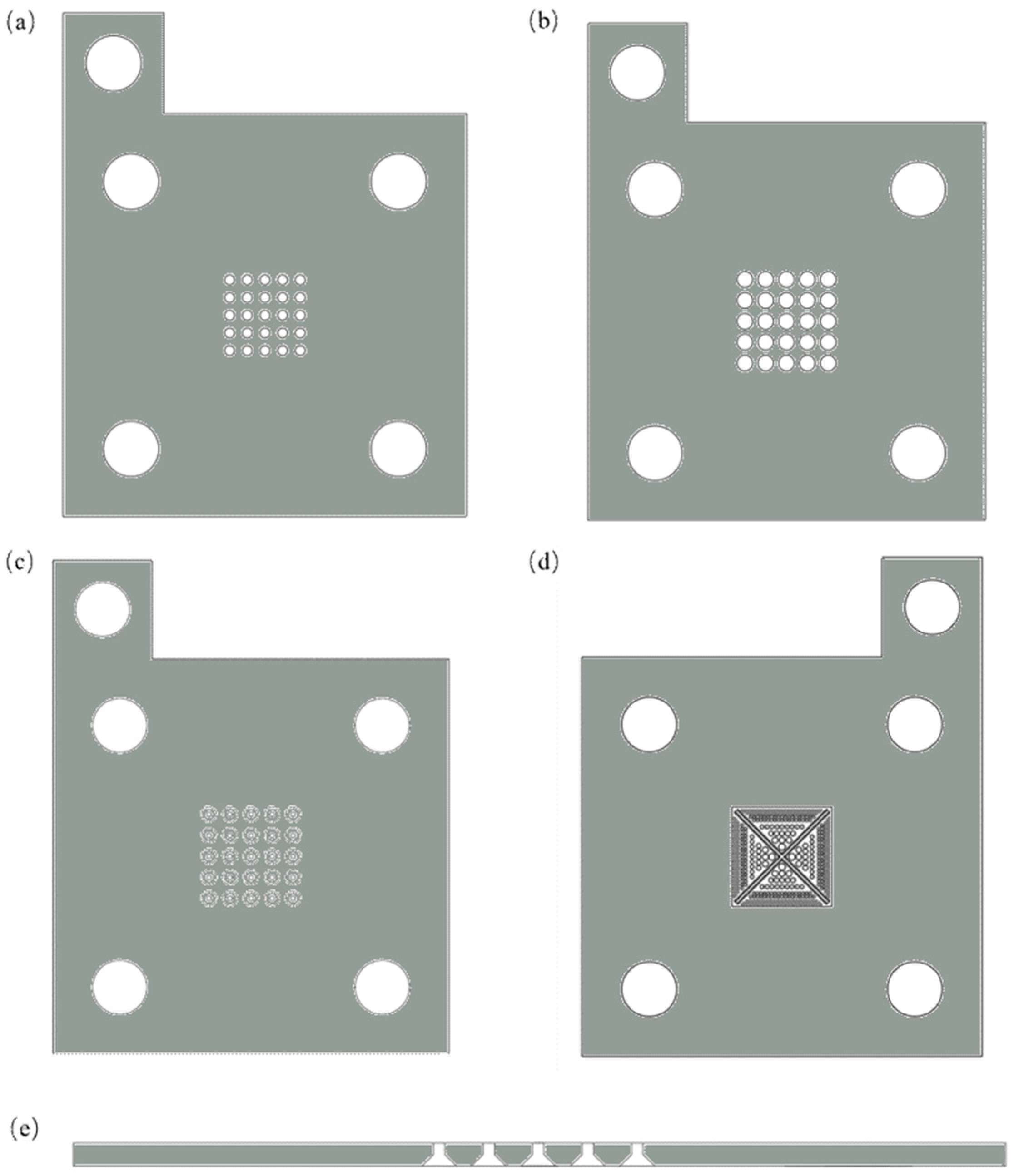
2.6. Current Collectors Design

Four types of current collectors are used in this paper, namely the C1-type current collector and C2-type current collector applied to both poles; the SF-type current collector can only be used at the anode; and the X-type current collector can only be used at the cathode. All of them are 80 × 100 × 2 mm, and their effective region is the center part of 2 cm × 2 cm. Among them, the C1-type current collectors and C2-type current collectors are conventional designs, mainly used for comparison. Figure 3a depicts a C1-type current collector, while Figure 3b depicts a C2-type current collector. The C1-type consists of 25 cylindrical through holes with a diameter of 2 mm and a length of 2 mm, and the opening ratio is 19.6%. The C2-type consists of 25 cylindrical through-holes with a diameter of 3.2 mm and a length of 2 mm, with an opening ratio of 50.2%.
As represented in Figure 3c,e, the anode SF current collector is constructed with a scaled step-hole structure. The structure consists of two parts: an inflow zone near the methanol reservoir side and an outflow zone near the MEA side. The inflow zone consists of 25 circular through holes with a diameter of 1 mm and a length of 1 mm, and the outflow zone consists of 25 tapered holes (90° countersunk holes) with a length of 1 mm, with an aperture diameter of 1 mm on the surface connected to the inflow zone and an aperture diameter of 3 mm on the outside surface of the outflow zone. The opening ratios on the outside surfaces of the inflow zone and the outflow zone are 4.9% and 44.2%, respectively. In this design, the CO2 molecules generated by the reaction flow from the outflow zone to the inflow zone and the CO2 and the inflowing methanol molecules form a special kind of interface called the meniscus at the junction of the structure, which obstructs methanol transport. As the reaction progresses, the amount of CO2 produced increases, pushing the meniscus structure towards the fuel reservoir and forming CO2 bubbles. The carbon dioxide bubbles do not release immediately, but stick to the orifice and grow larger and larger until they expand to a critical value. This structure can reduce the methanol transport rate and alleviate methanol crossover in a high methanol concentration environment.
As represented in Figure 3d, the model used for the cathode X-type current collector is relatively complex. The center is composed of a pair of crossed rectangular slant platforms, combined with circular through-holes with varying radius, and the opening ratio reaches 40.2%. This design combines the advantages of various collectors, and the cross-tilted platforms in the center allow the water generated to be discharged in time, preventing the cathode from being flooded. Circular through-holes of different sizes are used as a gradient structure, resulting in a smoother oxygen transfer and dramatically improving the mass transfer efficiency at the cathode, thereby improving the cell performance.

3. Results

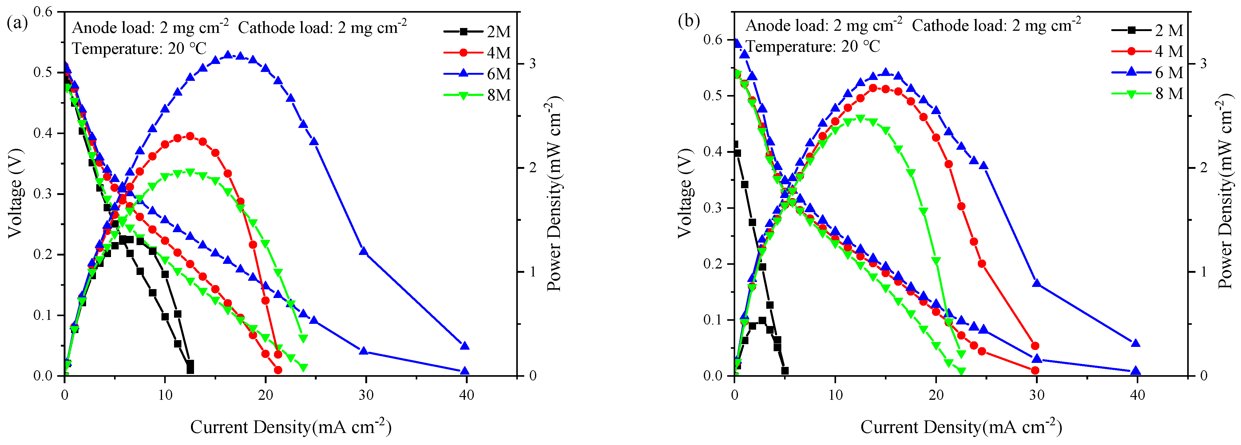
3.1. Cell Performance with Anode SF-Type Current Collector

The polarization curves of the C1-C1 current collector combinations were first tested during cell operation, as represented in Figure 4a. A conclusion can be drawn that the trend of the cell performance is proportional to the concentration from 2 M to 6 M, and the maximum power density reaches 3.08 mW cm−2 at 6 M. However, from 6 M to 8 M, the further increase in methanol concentration leads to a deterioration of cell performance, and the maximum power density at 8 M is only 1.97 mW cm−2. The performance is reduced by 36.0% compared to the maximum power density at 6 M. The performance of passive DMFCs is closely related to the concentration of methanol. When the concentration of methanol is low, the main factor affecting the performance of the cell is the reaction rate of methanol. As the methanol concentration increases, the delivery rate of methanol to the anode CL increases, the reaction of methanol is more complete, the ultimate current density that can be achieved is greater, and the cell performance is improved. But in the meantime, methanol crossover begins to increase, and the impact on cell performance can no longer be ignored. When the methanol concentration reached a certain value, the adverse effects caused by methanol crossover replaced the oxidation reaction rate and became the main obstacle to increasing the power. At this point, the mixed potential from oxidation became larger after methanol penetration, and the cell power began to decline. The methanol concentration at which the cell power peaks is the optimum methanol concentration.
The polarization curves of the SF-C1 current collector combinations were next tested under the same conditions using the same MEA, as represented in Figure 4b. Similarly, with the methanol concentration increasing from 2 M to 6 M, the cell performance gradually increased, and the maximum power density of 2.91 mW cm−2 was reached at 6 M. From 6 M to 8 M, the cell performance decreased, with a maximum power density of 2.48 mW cm−2 at 8 M. Compared to the maximum power density at 6 M, the performance decreased by 14.7%.
Comparing the two combinations, a conclusion can be drawn that while the cathode current collector is C1-type, the anode with SF design does not improve the optimal methanol concentration but slows down the performance loss of the cell in a high methanol environment. It still has a power density of 2.5 mW cm−2 at an 8 M environment, and the performance decline rate is less than that of the C1-type current collector. It shows that the design can reduce methanol crossover at high methanol concentrations.
To further verify the superiority of this design of the SF-type current collector during cell operation, the polarization curves of the C2-C2 current collector combination and the SF-C2 current collector combination were also tested. As represented in Figure 5, for the C2-C2 current collector combination, as the methanol concentration increases from 2 M to 6 M, the cell performance gradually increases, and the maximum power density of 3.56 mW cm−2 is reached at 6 M. For the SF-C2 current collector combination, the optimal methanol concentration is increased to 8 M, and the maximum power density is increased to 5.40 mW cm−2, a 51.6% improvement over the conventional design. The test results show that the SF-type current collector combination applied to the anode can indeed improve the performance of the cell and increase the optimal methanol concentration. The design of the SF-type current collector increases the resistance of the mass transfer process, which reduces the methanol transfer rate, and is responsible for the increase in the optimum methanol concentration and power. As the methanol concentration increases, the methanol reaction at the anode CL becomes more sufficient, the methanol crossover reduces, and the cathodic overpotential decreases, which improves the cell performance.
The difference between the C2-type current collector and the C1-type current collector is the different aperture of each circular hole, i.e., the final opening ratio is different, the opening ratio of the C1-type current collector is 19.6%, and the opening ratio of C2-type current collector is 50.2%. This difference resulted in not only an increase in the maximum power density of the cell, but also an increase in the optimal methanol concentration from 6 M to 8 M when using the C2-type current collector. This shows that the opening ratio has an impact on the improvement of cell performance in this study, and the C2-type current collector is better than the C1-type current collector, so the subsequent study will use the C2-type current collector as a control group.

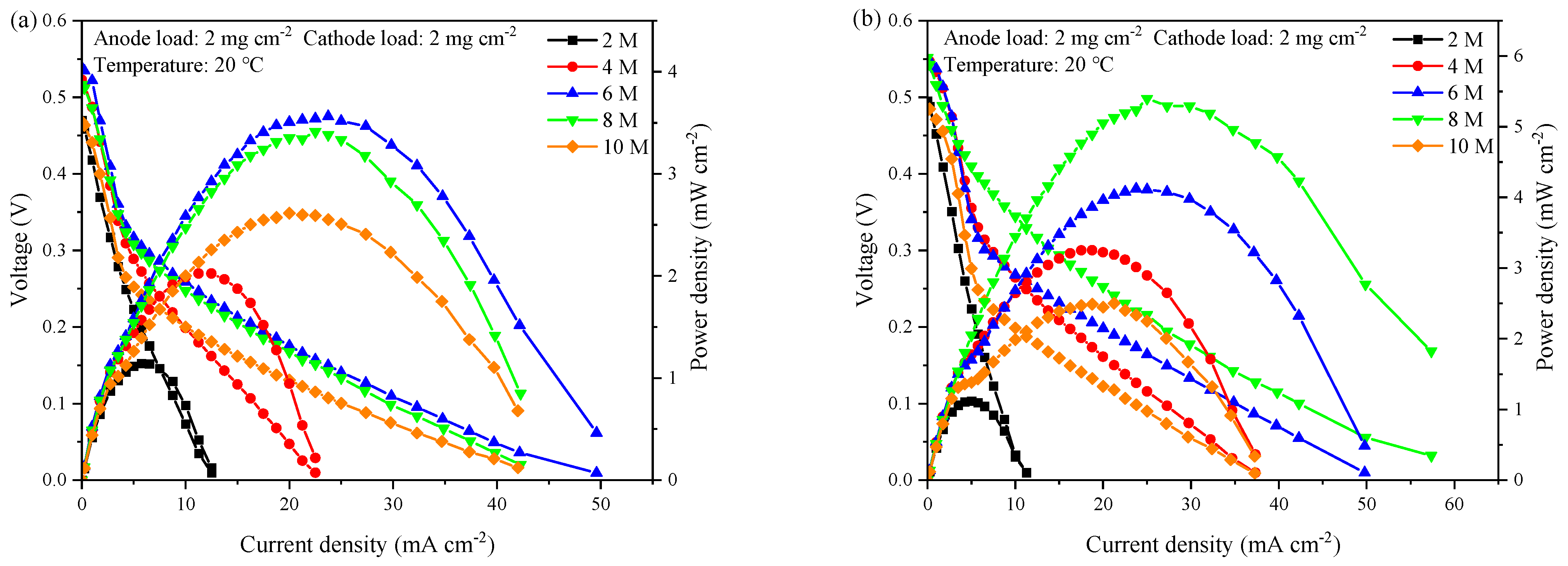
3.2. Cell Performance with Cathode X-Type Current Collector

The polarization curves of the C2-X current collector combinations were tested, as represented in Figure 6b. A conclusion can be drawn that as the methanol concentration increases from 2 M to 10 M, the cell performance continues to improve, and the maximum power density reaches 5.65 mW cm−2 at 10 M. From 10 M to 12 M, the cell performance decreases, with a maximum power density of 4.2 mW cm−2 at 12 M.
Compared with the C2-type current collector, the X-type current collector has the highest power density of 5.65 mW cm−2, a 58.7% improvement in performance, and the optimal methanol concentration is increased from 6 M to 10 M. The improved performance of the cell can be attributed to the design of the X-type current collector, which makes the oxygen in the air better diffuse to the CL—thus, the oxygen transport at the cathode side is improved, especially at higher current densities—and making this reaction more adequate, which directly increases the maximum current density that the cell can achieve. On the other hand, the improvement on the cathode side resulted in a more adequate overall reaction of the cell, increasing the utilization of methanol on the anode side, reducing methanol crossover, and increasing the optimal methanol concentration.

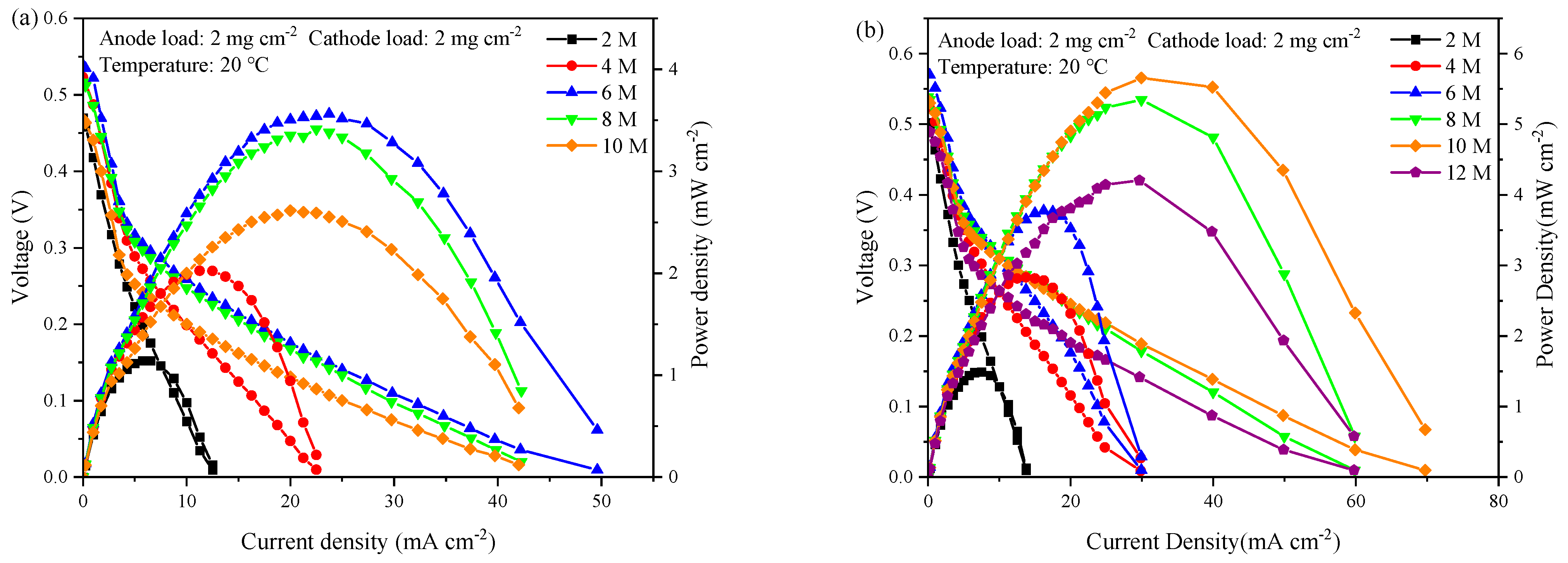
3.3. Polarization Curve of SF-X Current Collector Combination

To derive the optimal combination, the polarization curves of the SF-X current collector combination were tested by combining an X-type current collector functioning at the cathode with an SF-type current collector functioning at the anode, as represented in Figure 7a. A conclusion can be drawn that as the methanol concentration increases from 2 M to 8 M, the cell performance continues to improve, and the maximum power density reaches 6.22 mW cm−2 at 8 M. This is due to the fact that in passive DMFCs, the main mode of methanol transport is natural diffusion, and increasing the feed concentration of methanol will definitely lead to an increase in the rate of methanol transport to the CL, thus reducing the concentration polarization loss at the anode. Although the increase in methanol concentration will certainly make the methanol crossover rate increase, the increased methanol concentration on the anode side results in a lower water concentration on that side, which increases the diffusion of water back to the anode. This will avoid cathode flooding, allowing the cathode side to perform more efficient water management and increase oxygen diffusion to the catalyst sites, thereby increasing the oxygen reduction rate and reducing cathode activation losses. And the oxidation reaction that occurs therein will increase the heat production rate of the cell, which causes an increase in the operating temperature. In general, the cell performance is improved. However, when the methanol concentration further increases, e.g., to 10 M, the methanol crossover rate becomes too high, and the O2 of the cathode reacts with the permeating methanol, resulting in the simultaneous existence of two reactions of methanol oxidation and oxygen reduction in the cathode CL, which produces a mixed potential. And incomplete oxidation of methanol on the cathodic Pt catalyst leads to catalyst poisoning as a byproduct of this reaction and prevents oxygen from entering the CL and the catalyst active sites. This results in a reduced rate of oxygen reduction and an increased loss of cathode activation, affecting the cell voltage and reducing the cell output power. At this point the gain from the reduced concentration polarization loss can no longer compensate for the loss of performance from the methanol crossover, so the cell performance is significantly reduced.
As represented in Figure 7b, comparing the four combinations tested, it can be found that the SF-X combination has the best cell performance compared to other combinations, but the optimal methanol concentration is not the same as in the C2-X current collector combination. Due to the excellent performance of the cathode X-type current collector, the overall reaction of the cell is more adequate and the performance is improved, but at the same time, the restriction of the SF-type current collector on the methanol transport on the anode side is reduced, and the influence of methanol crossover is intensified, resulting in the optimal methanol concentration that should be reached at 10 M being advanced to 8 M.
As represented in Table 2, compared with previous work, in terms of power density, the catalyst load used in this work is relatively low. The catalyst loads for both the anode and cathode are 2 mg cm−2, while the specific power per unit mass of platinum is higher than in some work. In terms of the optimal methanol concentration, this design has increased it, making it more in line with the direction of commercial development.

3.4. Constant Current Discharge Test

To investigate whether this design affects the stability of passive DMFCs at different concentrations, constant current discharge tests were also performed, the current density at higher performance was selected, and the constant current density was 20 mA cm−2. For comparison, the test results of the C2-C2 combination and the SF-C2 combination were selected. Due to the low cell performance at a methanol concentration of 2 M, this concentration was not considered in the constant current discharge test. As represented in Figure 8, the discharge curves of the two current collector combinations are relatively stable at different methanol concentrations. For Figure 8a, it can be easily interpreted that the DMFC under the C2-C2 current collector combination has the most excellent performance at 6 M, below or above which the cell voltage drops. For Figure 8b, when the methanol concentration is increased from 4 M to 8 M, the average voltage of the cell increases and reaches an optimum point at 8 M, after which the average voltage begins to decline. The constant current test results for the two current collector combinations are consistent with the polarization curve test results. The difference in cell performance decline between the two current collector combinations is not significant, indicating that the main factor affecting stability of the cell is the MEA, and the proportion of different current collector designs is not significant.

4. Conclusions

In this paper, an anode SF-type current collector and a cathode X-type current collector were designed and fabricated for application in passive DMFCs. The performance of different collector combinations at various concentrations of methanol was tested, which started from 2 M and increased at 2 M intervals to the highest concentration of 12 M. The experiment was conducted at room temperature: 20 °C. The SF-type current collector applied to the anode had a scaled stepped pore structure with substantial variation in the opening ratio between the inflow and outflow zones, which increased the transport resistance of methanol and reduced methanol crossover. The test results showed that the SF-type current collector outperformed the C2-type with the same cathode structure, with the SF-type current collector DMFCs achieving the highest cell performance at a methanol concentration of 8 M, and the C2-type current collector achieving the highest cell performance at a methanol concentration of 6 M, respectively. The design of the SF-type current collector increased the mass transfer resistance, resulting in a lower methanol transport rate, a more adequate methanol reaction at the anode CL as the methanol concentration increases, and a reduced methanol penetration, which reduces the cathode overpotential, leading to improved cell performance.
The X-type current collector used at the cathode combines the advantages of a perforated current collector and one with a parallel channel to improve the oxygen transport at the cathode side while avoiding cathode flooding, thus improving the cell performance. The test results show that the X-type current collector outperformed the C2-type with the same anode collector, achieving a maximum power density of 5.65 mW cm−2, which is a 58.7% improvement in performance compared to the conventional design. Additionally, the optimal methanol concentration is increased from 6 M to 10 M. The combination of an anode SF-type current collector and a cathode X-type current collector obtained the highest power density at 6.22 mW cm−2. Compared to prior studies, the anode and cathode catalyst loading used in this paper were 2 mg cm−2, which is lower than other studies, resulting in a cheaper cost and greater specific power per unit mass of Pt. The successes in improving the cell power density together with increasing the applied concentration of methanol solution imply that the effective design of the current collector is a promising approach for advancing the usability of passive DMFCs. The improvement of passive DMFCs’ power density will broaden their scenario broader, no longer limited to micro-small portable devices, while the improvement of the optimal methanol concentration will allow it to carry higher concentrations of methanol solution with the same volume of methanol storage tank, greatly extending the cell runtime. With the continuous improvement of these two directions in subsequent works, the passive DMFC will have a broader prospect in the near future.

Author Contributions

Conceptualization, W.Y., Z.X. and Q.X.; methodology, W.Z., Z.L., X.Y. and H.S.; validation, W.Y., Z.X. and Q.X.; formal analysis, W.Y., Z.X. and Q.X.; investigation, W.Z., Q.M. and Z.L.; resources, X.Y. and H.S.; data curation, W.Y. and Z.X.; writing—original draft preparation, W.Y.; writing—review and editing, Z.X. and Q.X.; visualization, W.Y.; supervision, Q.M. and Q.X.; project administration, L.X. and Q.X.; funding acquisition, L.X. and Q.X. All authors have read and agreed to the published version of the manuscript.

Funding

This project was funded by the National Nature Science Foundation of China (No. 21978118), the Jiangsu Natural Science Foundation (No. BK20231323), and the State Key Laboratory of Engines at Tianjin University (No. K2020-14).

Data Availability Statement

All data are presented in the main text.

Conflicts of Interest

The authors declare no conflicts of interest.

References

  1. Xu, Q.; Zhang, F.H.; Xu, L.; Leung, P.; Yang, C.Z.; Li, H.M. The applications and prospect of fuel cells in medical field: A review. Renew. Sustain. Energy Rev. 2017, 67, 574–580. [Google Scholar] [CrossRef]
  2. Wu, Q.X.; Zhao, T.S.; Chen, R.; An, L. A sandwich structured membrane for direct methanol fuel cells operating with neat methanol. Appl. Energy 2013, 106, 301–306. [Google Scholar] [CrossRef]
  3. Kim, Y.S.; Peck, D.H.; Kim, S.K.; Jung, D.H.; Lim, S.; Kim, S.H. Effects of the microstructure and powder compositions of a micro-porous layer for the anode on the performance of high concentration methanol fuel cell. Int. J. Hydrogen Energy 2013, 38, 7159–7168. [Google Scholar] [CrossRef]
  4. Shin, J.; Nho, Y.C.; seon Hwang, I.; Fei, G.; Kim, A.R.; Nahm, K.S. Irradiated PVdF-HFP–tin oxide composite membranes for the applications of direct methanol fuel cells. J. Membr. Sci. 2010, 350, 92–100. [Google Scholar] [CrossRef]
  5. Yousefi, S.; Zohoor, M. Conceptual design and statistical overview on the design of a passive DMFC single cell. Int. J. Hydrogen Energy 2014, 39, 5972–5980. [Google Scholar] [CrossRef]
  6. Kamarudin, S.K.; Achmad, F.; Daud, W.R.W. Overview on the application of direct methanol fuel cell (DMFC) for portable electronic devices. Int. J. Hydrogen Energy 2009, 34, 6902–6916. [Google Scholar] [CrossRef]
  7. Wu, Q.X.; Zhao, T.S.; Chen, R.; Yang, W.W. Enhancement of water retention in the membrane electrode assembly for direct methanol fuel cells operating with neat methanol. Int. J. Hydrogen Energy 2010, 35, 10547–10555. [Google Scholar] [CrossRef]
  8. Kamarudin, S.K.; Daud, W.R.W.; Ho, S.L.; Hasran, U.A. Overview on the challenges and developments of micro-direct methanol fuel cells (DMFC). J. Power Sources 2007, 163, 743–754. [Google Scholar] [CrossRef]
  9. Yang, W.; Chou, S.; Shu, C. Effect of current-collector structure on performance of passive micro direct methanol fuel cell. J. Power Sources 2007, 164, 549–554. [Google Scholar] [CrossRef]
  10. de Sa, M.H.; Pinto, A.M.F.R.; Oliveira, V.B. Passive direct methanol fuel cells as a sustainable alternative to batteries in hearing aid devices—An overview. Int. J. Hydrogen Energy 2022, 37, 47. [Google Scholar] [CrossRef]
  11. Carneiro, L.P.; Ferreira, N.S.; Tavares, A.P.; Pinto, A.M.; Mendes, A.; Sales, M.G.F. A passive direct methanol fuel cell as transducer of an electrochemical sensor applied to the detection of carcinoembryonic antigen. Biosens. Bioelectron. 2021, 175, 112877. [Google Scholar] [CrossRef]
  12. Ferreira, N.S.; Carneiro, L.P.; Viezzer, C.; Almeida, M.J.; Marques, A.C.; Pinto, A.M.; Fortunato, E.; Sales, M.G.F. Passive direct methanol fuel cells acting as fully autonomous electrochemical biosensors: Application to sarcosine detection. J. Electroanal. Chem. 2022, 922, 116710. [Google Scholar] [CrossRef]
  13. Carneiro, L.P.; Pinto, A.M.; Mendes, A.; Sales, M.G.F. An all-in-one approach for self-powered sensing: A methanol fuel cell modified with a molecularly imprinted polymer for cancer biomarker detection. J. Electroanal. Chem. 2022, 906, 116009. [Google Scholar] [CrossRef]
  14. Ong, B.C.; Kamarudin, S.K.; Basri, S. Direct liquid fuel cells: A review. Int. J. Hydrogen Energy 2017, 42, 10142–10157. [Google Scholar] [CrossRef]
  15. Alias, M.S.; Kamarudin, S.K.; Zainoodin, A.M.; Masdar, M.S. Active direct methanol fuel cell: An overview. Int. J. Hydrogen Energy 2020, 45, 19620–19641. [Google Scholar] [CrossRef]
  16. Bresciani, F.; Rabissi, C.; Zago, M.; Gazdzicki, P.; Schulze, M.; Guétaz, L.; Escribano, S.; Bonde, J.L.; Marchesi, R.; Casalegno, A. A combined in-situ and post-mortem investigation on local permanent degradation in a direct methanol fuel cell. J. Power Sources 2016, 306, 49–61. [Google Scholar] [CrossRef]
  17. Yaqoob, L.; Noor, T.; Iqbal, N. Recent progress in development of efficient electrocatalyst for methanol oxidation reaction in direct methanol fuel cell. Int. J. Energy Res. 2021, 45, 6550–6583. [Google Scholar] [CrossRef]
  18. Alias, M.S.; Kamarudin, S.K.; Zainoodin, A.M.; Masdar, M.S. Structural mechanism investigation on methanol crossover and stability of a passive direct methanol fuel cell performance via modified micro-porous layer. Int. J. Energy Res. 2021, 45, 12928–12943. [Google Scholar] [CrossRef]
  19. Shrivastava, N.K.; Thombre, S.B.; Motghare, R.V. Wire mesh current collectors for passive direct methanol fuel cells. J. Power Sources 2014, 272, 629–638. [Google Scholar] [CrossRef]
  20. Gholami, O.; Imen, S.J.; Shakeri, M. Effect of anode and cathode flow field geometry on passive direct methanol fuel cell performance. Electrochim. Acta 2015, 158, 410–417. [Google Scholar] [CrossRef]
  21. Mallick, R.K.; Thombre, S.B.; Shrivastava, N.K. A critical review of the current collector for passive direct methanol fuel cells. J. Power Sources 2015, 285, 510–529. [Google Scholar] [CrossRef]
  22. Braz, B.A.; Moreira, C.S.; Oliveira, V.B.; Pinto, A.M.F.R. Effect of the current collector design on the performance of a passive direct methanol fuel cell. Electrochim. Acta 2019, 300, 306–315. [Google Scholar] [CrossRef]
  23. Chan, Y.H.; Zhao, T.S.; Chen, R.; Xu, C. A small mono-polar direct methanol fuel cell stack with passive operation. J. Power Sources 2008, 178, 118–124. [Google Scholar] [CrossRef]
  24. Wu, Q.X.; Zhao, T.S.; Chen, R.; Yang, W.W. A microfluidic-structured flow field for passive direct methanol fuel cells operating with highly concentrated fuels. J. Micromech. Microeng. 2010, 20, 045014. [Google Scholar] [CrossRef]
  25. Zhang, Y.F.; Yuan, Z.Y.; Li, Y.L.; Jia, Q.; Chen, S.; Liu, X.W. Design and fabrication of a silicon-based direct methanol fuel cell with a new cathode spoke structure. J. Power Sources 2011, 196, 3015–3025. [Google Scholar] [CrossRef]
  26. Gholami, O.; Imen, S.J.; Shakeri, M. Effect of non-uniform parallel channel on performance of passive direct methanol fuel cell. Int. J. Hydrogen Energy 2013, 38, 3395–3400. [Google Scholar] [CrossRef]
  27. Mallick, R.K.; Thombre, S.B. Performance of passive DMFC with expanded metal mesh current collectors. Electrochim. Acta 2017, 243, 299–309. [Google Scholar] [CrossRef]
  28. Raghavaiah, N.V.; Srinivasulu, G.N. Analysis and experimental investigation on passive direct methanol fuel cell current collectors with taper cylindrical openings. Fuel Cells 2022, 22, 169–185. [Google Scholar] [CrossRef]
  29. Dong, H.; Su, H.M.; Chen, Z.; Yu, H.; Yu, H.B. Fabrication of Electrochemically Reduced Graphene Oxide Modified Gas Diffusion Electrode for In-situ Electrochemical Advanced Oxidation Process under Mild Conditions. Electrochim. Acta 2016, 222, 1501–1509. [Google Scholar] [CrossRef]
  30. Guan, L.; Yu, W.; Asghar, M.R.; Zhang, W.; Su, H.; Li, C.; Xing, L.; Xu, Q. Effect of graphene aerogel as a catalyst layer additive on performance of direct methanol fuel cell. Fuel 2024, 360, 130503. [Google Scholar] [CrossRef]
  31. Kang, K.; Lee, G.; Gwak, G.; Choi, Y.; Ju, H. Development of an advanced MEA to use high-concentration methanol fuel in a direct methanol fuel cell system. Int. J. Hydrogen Energy 2012, 37, 6285–6291. [Google Scholar] [CrossRef]
  32. Braz, B.A.; Oliveira, V.B.; Pinto, A.M.F.R. Optimization of a passive direct methanol fuel cell with different current collector materials. Energy 2020, 208, 118394. [Google Scholar] [CrossRef]
Figure 1. Principle of passive DMFCs.
Catalysts 14 00632 g001
Figure 2. Each component of the cell and the actual picture after combinations (1: anode end plate; 2: anode methanol storage tank; 3: gasket; 4: MEA; 5: anode current collector, 6: cathode current collector; 7: cathode end plate).
Catalysts 14 00632 g002
Figure 3. (a) C1-type current collector; (b) C2-type current collector; (c) SF-type current collector; (d) X-type current collector; (e) Cross-section of SF-type current collector.
Catalysts 14 00632 g003
Figure 4. Polarization curves of the two current collector combinations: (a) C1-C1 current collector combinations; (b) C1-SF current collector combinations.
Catalysts 14 00632 g004
Figure 5. Polarization curves of the two current collector combinations at different methanol concentrations: (a) C2-C2 current collector combinations; (b) SF-C2 current collector combinations.
Catalysts 14 00632 g005
Figure 6. Polarization curves of the two current collector combinations: (a) C2-C2 current collector combination; (b) C2-X current collector combination.
Catalysts 14 00632 g006
Figure 7. (a) Polarization curves of the SF-X current collector combinations at different methanol concentrations; (b) Maximum power density of each current collector combination at different methanol concentrations.
Catalysts 14 00632 g007
Figure 8. Constant current discharge test of two current collector combinations at different methanol concentrations: (a) C2-C2 current collector combinations, (b) SF-C2 current collector combinations.
Catalysts 14 00632 g008
Table 1. Comparison of current collector material properties [32].
MaterialDensity (g/cm3)Electrical Conductivity (S/m)Material Cost (USD)Processing Cost (USD)Total Cost (USD)
Stainless steel (316 L)7.991.33 × 1073.092.535.62
Titanium (TA2)4.514.30 × 1073.373.667.03
Graphite plate2.26.5 × 1031.6916.5918.28
Table 2. Performance comparison of the SF-type current collector and X-type current collector with previous studies.
Current Collector DesignOperating TemperatureOptimum Methanol ConcentrationAnode and Cathode Catalyst Load
(mg cm−2)
Power Density
(mW cm−2)
Ref.
SF-type20 °C8 M2; 25.40This Study
X-type20 °C10 M2; 25.65This Study
SF-X20 °C8 M2; 26.22This Study
perforated CC-2 M3; 1.33.14[22]
spoke structure20 °C1 M4; 414.79[25]
EMCC25 °C3 M4; 23.04[27]
taper cylindrical-3 M4; 27.06[28]
Disclaimer/Publisher’s Note: The statements, opinions and data contained in all publications are solely those of the individual author(s) and contributor(s) and not of MDPI and/or the editor(s). MDPI and/or the editor(s) disclaim responsibility for any injury to people or property resulting from any ideas, methods, instructions or products referred to in the content.

