Review

Ca-, Mg-, Sc-, and Y-Stabilized Zirconia: High-Performance Support Material for Dry Reforming of Methane and Solid-Electrolyte Material for Fuel Cell

by
Salma A. Al-Zahrani
1,
Yuvrajsinh Rajput
2,
Kirankumar J. Chaudhary
2,
Ahmed S. Al-Fatesh
3,*,
Fekri Abdulraqeb Ahmed Ali
4,
Ahmed Mohamed El-Toni
5,
Abdulaziz A. M. Abahussain
3,
Rayed Alshareef
6,
Rawesh Kumar
2 and
Ahmed I. Osman
7,*
1
Chemistry Department, Faculty of Science, University of Ha’il, P.O. Box 2440, Ha’il 81451, Saudi Arabia
2
Department of Chemistry, Indus University, Ahmedabad 382115, Gujarat, India
3
Chemical Engineering Department, College of Engineering, King Saud University, Riyadh 11421, Saudi Arabia
4
Chemical Engineering Department, College of Engineering, Imam Mohammad Ibn Saud Islamic University (IMSIU), Riyadh 11432, Saudi Arabia
5
King Abdullah Institute for Nanotechnology, King Saud University, Riyadh 11451, Saudi Arabia
6
Department of Chemical Engineering, College of Engineering at Yanbu, Taibah University, Yanbu Al-Bahr 41911, Saudi Arabia
7
School of Engineering, Technology, and Design, Canterbury Christ Church University, Canterbury CT1 1QU, UK
*
Authors to whom correspondence should be addressed.
Catalysts 2025, 15(4), 300; https://doi.org/10.3390/catal15040300
Submission received: 21 January 2025 / Revised: 5 March 2025 / Accepted: 13 March 2025 / Published: 21 March 2025

Abstract

:
Our planet is currently facing dual challenges of global warming and energy crisis. The heavy reliance of the energy sector on fossil fuels significantly contributes to the accumulation of greenhouse gases, such as CH4 and CO2, in the environment atmosphere, exacerbating global warming. Stabilized zirconia-based material offer a promising solutions to address both challenges. As a catalytic support material, active sites incorporated stabilized-zirconia can facilitate the conversions of greenhouse gases like CH4 and CO2 into syngas (H2 and CO). This reaction is popularly known as dry reforming of methane (DRM). Additionally, stabilized zirconia-based materials act as solid-state electrolyte in fuel cells enabling the electrochemical conversion of H2 and O2 to generate electricity. Both processes require high-temperature stability and oxide ionic conductivity, making “Ca, Mg, Sc, Y-stabilized zirconia” an optimal choice. In DRM, the key factors influencing catalytic efficiency include metal–support interaction, reducibility, and basicity. Meanwhile, for solid oxide fuel cells, performance is governed by factors such as size-fit, charge imbalance, dopant miscibility, ion conducting phases, densification, electrolyte thickness, and grain boundary volume. This compressive review explores the dual functionality of “Ca, Mg, Sc, Y-stabilized zirconia” as a catalyst’support for DRM and as an solid electrolyte for fuel cells. The most promising research outcomes are highlighted, and future research directions are outlined. By bringing together the catalytic and fuel cell research communities, this study aims to advance sustainable energy technologies and contribute to mitigating environmental and energy crisis through the development of stabilized zirconia-based materials.

Graphical Abstract

1. Introduction

Earth is the only known planet that supports life, yet it is increasingly threatened by global warming. This environmental crisis is intensifying due to the world’s growing energy demands and the persistent dependence on fossil fuels. The energy sector, which heavily relies on petroleum and coal, continues to release large volumes of greenhouse gases (GHGs) into the atmosphere. This ongoing accumulation of GHGs, including CO₂ and CH₄, exacerbates global warming, leading to severe climatic consequences year after year. Addressing this issue requires urgent shifts towards sustainable energy solutions to mitigate the environmental impact while meeting global energy demands. The implementation of dry reforming of the methane (DRM) reaction and a highly efficient fuel cell are the solutions for both. DRM reaction simultaneously consumes two major greenhouse gases, CH4 and CO2, converting them into syngas (H2 and CO). Syngas serves as a valuable feedstock in various industrial applications, including chemical synthesis and fuel production [1]. Meanwhile, fuel cells offer a clean energy alternative by generating electricity without direct greenhouse gas emissions, making them a sustainable solution for energy production. The integration of DRM and fuel cell technologies presents a promising approach to reducing greenhouse gas emissions while producing useful energy carriers. More than eight active metals (including noble metal), thirty-five promoters, and twelve supports are reported for this reaction [2]. Among cheap active metals, Ni and Co have gained the most attention, but Co is oxidized easily to the cobalt oxide and catalyzes the total oxidation of methane [3]. Again, the steric repulsion between “closed shell of Ni and CH4” is smaller than steric repulsion between “closed shell of Co and CH4”. So, the interaction energy of CH4 over Ni is many times higher than that of Co [4]. Overall, Ni brings major interest to the catalyst community than Co in developing a cheap catalyst system for DRM., It is an endothermic reaction, and the catalytic activity grows on increasing reaction temperature (up to 850 °C), but the problem is that metallic Ni sinters at high temperatures. As metallic Ni size grows, it becomes more selective for coke deposition and turns into catalytic deactivation very soon. Proper support that can sustain high reaction temperature and hold the metallic Ni (against sintering) at high reaction temperature is a major challenge to the catalytic community. Three thermal sustainable supports, silica, alumina, and stabilized zirconia, are recognized for their high-temperature operations. Silica support was reported for poor dispersion of Ni [5]. At the same time, alumina supports because of its inherent acidity (resulting in more coke deposition). The alumina-based support severely encounters the diffusion of active sites Ni into the bulk alumina lattice, which results in the loss of active sites at the catalytic surface [6]. Zirconia itself fluctuates at monoclinic, tetragonal, and cubic phases upon temperature implication, but when it comes to stabilized zirconia, stable zirconia phases (like tetragonal or cubic) constitute the crystalline framework. Zirconia-based supports are additionally facilitated by oxygen vacancy, mobile oxygen conduction in the lattice, and endowing lattice oxygen for instant oxidation of coke over the catalyst surface. That means stabilized zirconia support is more reliable for carrying metallic Ni against high-temperature DRM-like oxidation reactions. DRM reaction is carried out in a packed steel reactor equipped with a feed gas inlet, heating furnace, gas-feed outlet, and online gas chromatograph (Figure 1A) [7]. Gas feed is composed of CH4, CO2, and inert gas, where the typical ratio of CH4/CO2 is maintained at 1:1 (with the help of a gas flow controller). The heating furnace is fitted co-axially with the catalyst bed, and the temperature at the catalyst bed is monitored by a K-type thermocouple. The inlet and outlet gas compositions are analyzed by GC. In the target of preparing active sites for DRM, the catalyst is reduced under H2 at 600–900 °C. After reduction, the reactor temperature is set at a reaction temperature of DRM. The reaction scheme of DRM can be presented as a sequential breakdown of C-H (of CH4) over the step edge site of Ni, interaction as well as dissociation of CO2 (into CO and O*) over basic sites of the catalyst surface, oxidation of dissociated CH4 (CHx; x = 1–3) by adsorbed oxygen (O*). The simultaneous presence of Ni and Co facilitates cobalt-assisted oxidation of CHx species by CO2. The dissociated methane (CHx) is oxidized by cobalt oxide, and the reduced cobalt compound is further oxidized by CO2 (Figure 1B) [8]. This is an endothermic reaction and so the activity of a catalyst was reported from 650 to 900 °C reaction temperature. During the DRM, the concentration of various gases like CH4, CO2, H2, CO, H2O, and carbon are build up over the catalyst surface, and this situation presents initiation of several parallel reactions in the same temperature regime like reverse water gas shift reaction, carbon formation reaction, coke gasification, CO disproportionation reaction, etc. (Figure 1B). Some of the parallel reaction routes become thermodynamically feasible in a temperature regime and it affects the final product selectivity in the DRM reaction. For example, a reaction temperature at 800 °C for DRM is also found advantageous in term of thermodynamic feasibility. At about 800 °C, the endothermic nature of DRM speeds up the kinetic as well as CH4 decomposition reaction (CH4 → C +H2), and carbon gasification by water (C + H2O → CO + H2) becomes thermodynamically feasible [9]. Altogether, all these reactions turn into enhanced syngas production.
The stabilized zirconia has also proved its applicability as a solid oxide electrolyte in high-performance fuel cells as a solid oxide electrolyte which will be the ultimate solution for making clean energy without emission of greenhouse gases [10]. Fuel cell justifies an electrical pathway of the reaction of hydrogen and oxygen into water, which is completed by the emission of energy. This emitted energy, as well as the product water, are utilized for day-to-day work. Using solid oxide electrolytes in fuel cells gives the ultimate solution of high conductivity with the least leakage of current towards the clean energy pathways. The fuel cell which utilizes a solid oxide electrolyte is known as a solid oxide fuel cell (SOFC). This electrochemical device consists of three core components: the anode, cathode, and electrolyte, each playing a crucial role in the overall performance and efficiency of the SOFC [11]. The principle of solid oxide fuel cells (SOFCs) is based on oxygen ion-directed electrolytes. It has various benefits over others as acceptable materials, low resistance to contamination, and extremely high efficiency. In this fuel cell, ceramic is used as an electrolyte, and the charge carrier is O2−. It operates at high temperatures of 600–1000 °C. Solid oxide fuel cells have solid, dense electrolytes that are sandwiched between two porous electrodes [12,13,14,15]. SOFCs are specified by oxygen ion-directed electrolytes. When compared to other fuel cell types, solid oxide fuel cells (SOFCs) have several benefits, such as high efficiency in converting chemical energy from fuel to electrical power (>70% with fuel regeneration) [16] and low resistance of oxygen ion-directed electrolyte to contamination in the fuel. As fuel gas feeds, various types of gases like hydrogen, natural gas, and hydrocarbon can be fed up in the future, shortly as fuel cell technology advances [17]. The redox reaction is crucial to the operation of SOFCs. It takes place in five sequential steps. (1) The fuel H2 is oxidized into H+, and an electron is generated at the anode. (2) The generated electrons are carried to the cathode through the outer circuit. (3) At the cathode, molecular oxygen is reduced into oxide ion (O2−) by electrons. (4) O2− ion is diffused from the cathode to the anode through a solid electrolyte. (5) Lastly, the reaction between O2− and H+ at the cathode generates H2O. When electrons flow across an external circuit, the task of generating electrical energy is completed, as well as the reaction of O2− ions and hydronium ions inside the cell generates pure water. The complete redox cycle discussed above is free from the generation of greenhouse gases, which makes this fuel cell technology environmentally friendly. A systematic scheme of redox reactions, as well as charge transport pathways (in SOFCs), are shown in Figure 2.
The working temperature of the fuel cell and DRM reaction falls in the same temperature range (700–900 °C). Oxide ion conductivity and high-temperature sustainability make stabilized zirconia a promising support for Ni-based DRM catalysts as well as high-performance material for solid-state electrolytes in fuel cells. When a dopant is placed in the host, the radius of the dopant’s cation and the radius of the host’s cation may be matched, and the charge of the dopant’s cation and the host’s cation may not be matched. The first phenomenon is termed “size fit” and the second one is “charge disbalance”. The oxide vacancy is formed as a result of unmatched size and charge disbalance between host and guest metal cations in the lattice. The ionic conductivity in terms of “size fit”, “charge disbalance”, “oxide vacancies”, and “interface phenomena” are explored more in the SOFC material, whereas the surface reducibility and acid-base functionalities also become important for support application in DRM catalysis.
Both DRM reaction and SOFC’s working conditions require high temperatures (>600 °C), and seamless oxygen conduction. The doped zirconia materials have gathered significant attention “as catalysis support” in DRM and “as solid-state electrolyte material” in fuel cells due to oxygen-endowing capacity, enriched defects (providing a path for ion conduction), and high-temperature sustainability. Among the doped zirconia, Ca-, Mg-, Sc-, and Y-stabilized zirconia are investigated mostly in both fields. Herein, a conceptual and comprehensive review of the development of zirconia-supported DRM catalysts as well as oxygen ion conducting zirconia-based SOFCs are reviewed, and the potential/futuristic materials are outlined. This review brings both the electrochemical community and the catalytic community together to solve the environmental problem and the energy crisis jointly.

2. Synthetic Strategy for Preparation of Stabilized Zirconia Material

The nanosized “metal oxide stabilized zirconia” is synthesized via two approaches named “bottom-to-top approach” and “top-to-bottom approach”. In the bottom-to-top approach, synthesis is started with a metal precursor solution, and metal oxide matrixes are assembled up to the nanosize range, whereas in the top-to-bottom approach, synthesis is started with bulk metal oxide powder, it is crushed/milled/fragmented into finer particle so that majority of particle fall in the nano level. The heterogeneity of particle size always persists in the top-to-bottom approach.

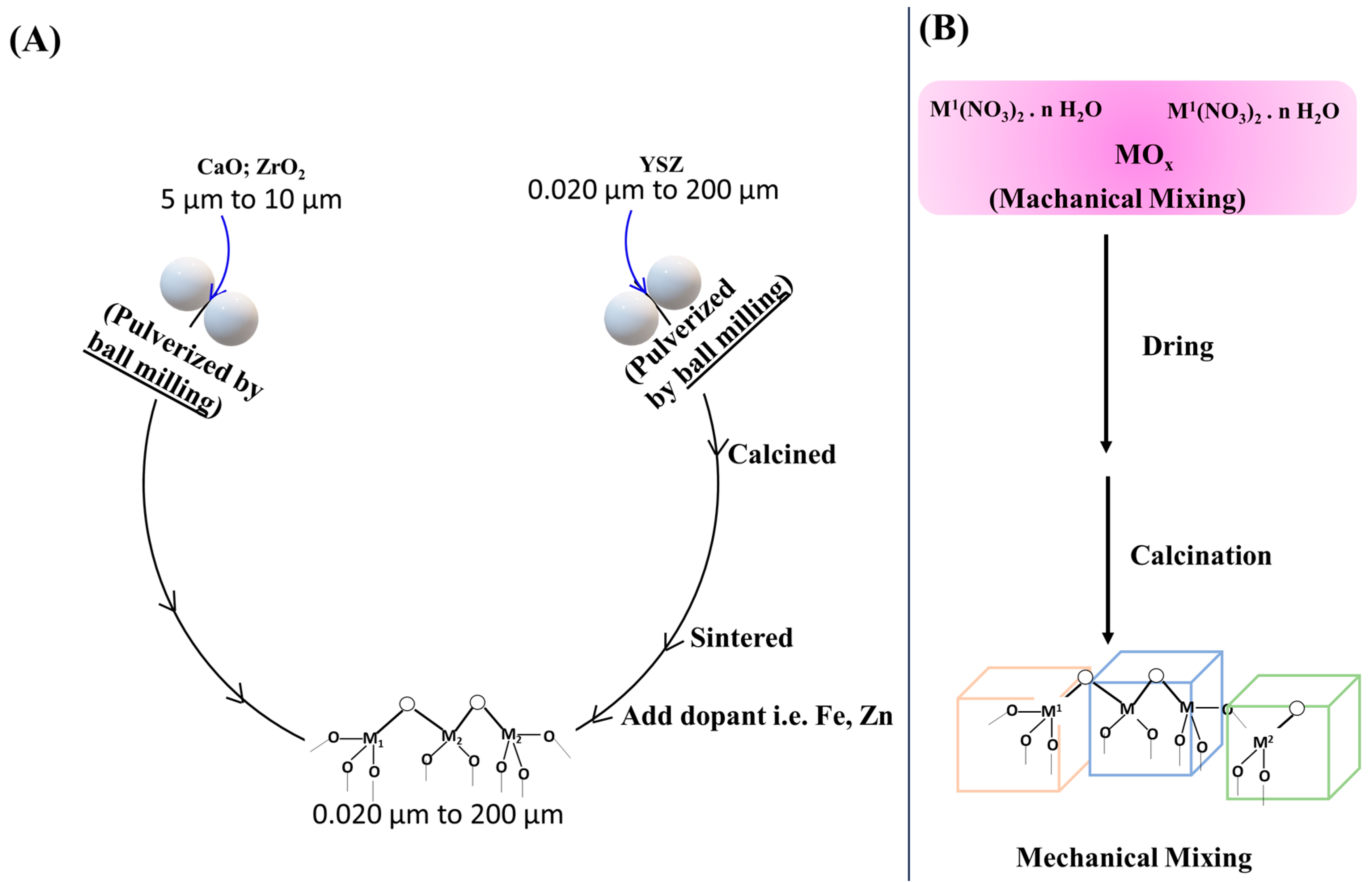
2.1. Top-to-Bottom Approach

Top-to-bottom approach synthesis is carried out using two procedures, namely, ball milling and mechanical mixing (Figure 3A). The ball-milling method is a cost-effective and scalable solid-state technique. In this process, different constituents of support metal oxides (like Y2O3, CaO, MgO, Sc2O3, ZrO2) are mechanically ground together, promoting uniform metal dispersion and increased surface area. Finally, the calcined powder mixture is milled to reduce the particle size and to improve the homogeneity of the mixture. The calcination treatment of these nanosized powders provides a chance for solid-state reaction between two metal oxides. The milled powder is then pressed into the desired shape using a hydraulic press (or other pressing equipment) for SOFC application [18]. The pressed powder is then sintered at high temperatures (typically between 1400–1600 °C) in a furnace to form a dense, solid oxide electrolyte [19]. This process helps to remove any impurities and to promote the formation of a homogeneous mixture [20].
Mechanical mixing is another method under the top-to-bottom approach. It is also a simple, cost-effective approach involving the dry blending of metal precursors (like nitrate of Ni, Co, Ru) with support materials (e.g., ZrO2). The mixture undergoes calcination and, if needed, reduction to activate the metal species (Figure 3B). This method ensures uniform metal dispersion, scalability, and control over metal loading while promoting metal–support interactions that enhance catalyst stability and performance toward DRM reaction [21].

2.2. Bottom-to-Top Approach

In the bottom-to-top approach, suitable metal precursor solutions are hydrolyzed, condensed and degraded into nanosized metal oxides. The nano-sized metal oxide is also stabilized over micro-level supports. In solid oxide fuel cells, the stabilized zirconia electrolyte is typically synthesized by different bottom-to-top approaches such as co-precipitation, sol-gel, and hydrothermal methods. However, in DRM catalysis, the impregnation method also had wide significance.

2.2.1. Impregnation Method

The impregnation method is a one-pot synthesis method, and its handy synthesis procedure makes it preferable to others. Based on the procedures, it is further differentiated into three subcategories: melt impregnation, wet impregnation, and co-impregnation. The melt-impregnation method is a catalyst preparation technique that involves impregnating a support material with a molten metal precursor, typically salts of metals like Ni, Co, or Pt. The molten precursor is absorbed by porous supports such as alumina, ceria, or zirconia, and after cooling, it solidifies to form metal salts or oxides within the support. The catalyst is then dried, calcined, and optionally reduced to metallic form (Figure 4A). This method offers advantages such as enhanced metal loading and improved catalyst stability, especially in bimetallic systems like Ni-Co or Ni–Cu [22]. The wet-impregnation method is widely used to prepare catalysts for DRM, which involves the deposition of metal precursor solution onto support materials such as zirconia under heating. The slurry is collected after water evaporation, and then it is dried and calcined at an appropriate temperature [22]. The impregnation method allows for exposing the maximum number of active sites over the catalyst surface. If the impregnation of the second metal is carried out after the impregnation of the first metal over the support, then such impregnation is called stepwise impregnation (Figure 4B). In stepwise impregnation, there is a chance of hindrance of earlier metal oxide (which is impregnated during first impregnation) by later metal oxide (which is impregnated during second impregnation), which can affect the catalytic activity towards DRM.
The co-impregnation method is a widely used technique for preparing DRM catalysts, involving the simultaneous impregnation of multiple metal precursors (e.g., Ni, Co, Ru) onto a support material (e.g., ZrO2) using a solution of metal salts. This method ensures uniform metal distribution, promotes synergistic effects between metals, and allows precise control over metal loading. After impregnation, the catalyst undergoes drying, calcination, and, if needed, reduction to activate the metals for the DRM reaction [23]. In co-impregnation, the hindrance of active sites by second metal oxide is minimized.

2.2.2. Vapour Deposition

The uniform thin film of solid material can be achieved by the chemical vapor deposition method. The target metal is vaporized (by laser or high-energy electron beam) and deposited on a substrate till supersaturation [24]. Supersaturation provides a large number of nucleation sites, which helps the formation of thin, uniform films. Further, self-assembly techniques have been employed to create heterostructures with abundant nanoscale interfaces and oxygen vacancies, leading to superior ionic conductivity and stability [25]. In addition to the development of new materials, optimizing the micro-structure and fabrication methods of existing electrolytes is crucial [25,26]. The tape casting method is integral to fabricating solid electrolytes in solid oxide fuel cells (SOFCs). This technique involves slurry formation (from powders, solvents, binders, plasticizers, and dispersants) followed by casting onto a flat surface to form a uniform tape. To achieve the desired micro-structures, the tape is dried, laminated, and thermally treated [27]. The slurry composition and casting parameters induce electrolyte density and mechanical integrity.

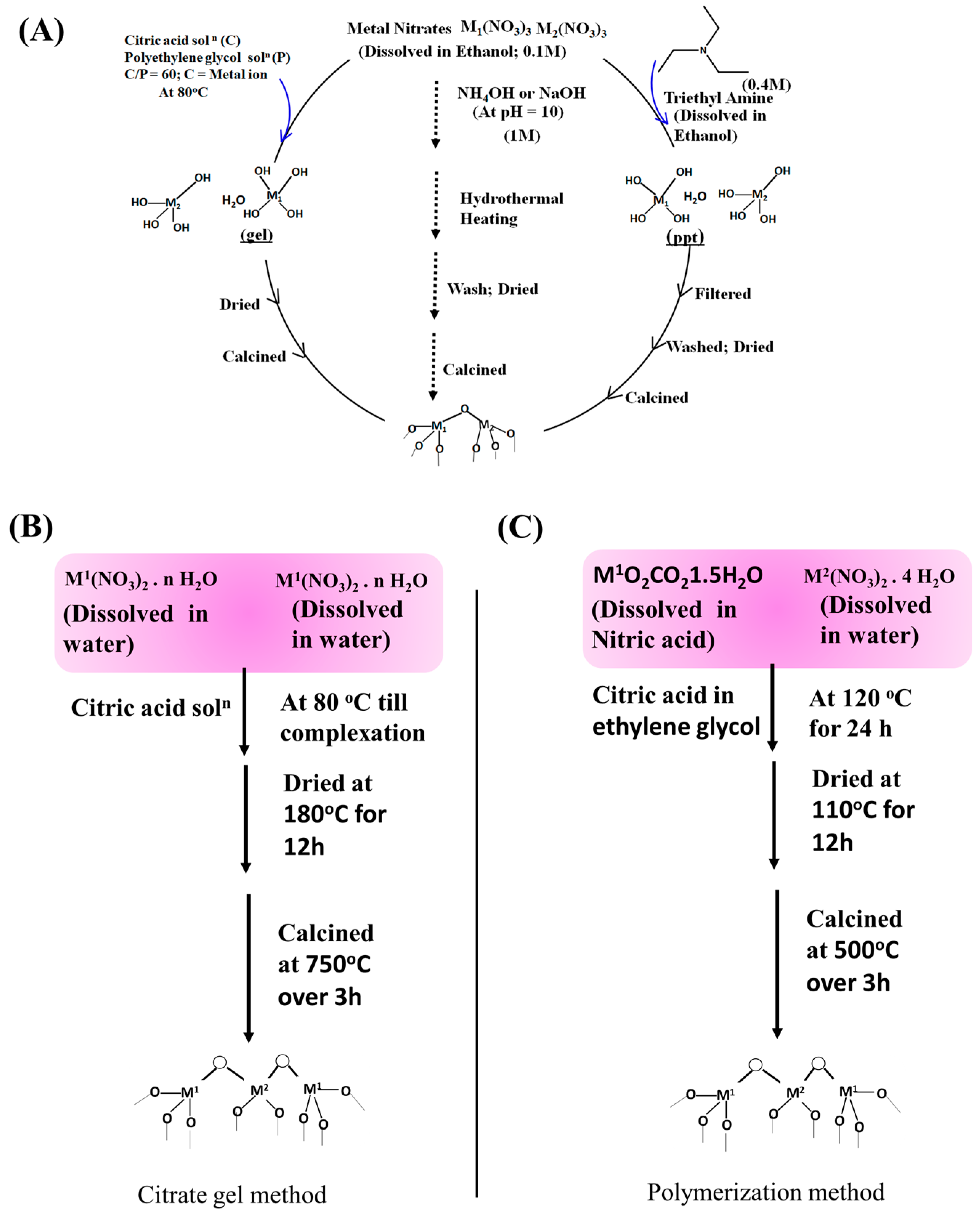
2.2.3. Co-Precipitation

Under the co-precipitation method, a desired strength of metal nitrate precursor solution (zirconium nitrate and stabilizing metal salt precursors) is hydrolyzed in the presence of an organic base like tri-ethyl amine solution (Figure 5A). It resulted in simultaneous precipitation of both metal hydroxides, which is further filtered and washed sequentially. The dried powder is then calcined at high temperatures to form the final stabilized zirconia electrolyte [28]. Co-precipitation allows for the precise control of the composition and particle size of the final product [29]. It also promotes strong metal–support interactions and leads to stable catalysts with improved resistance to sintering and coke formation, which is crucial for DRM performance [30]. The method requires careful control of the processing parameters to ensure the formation of a homogeneous gel and the removal of impurities during the washing and drying steps.

2.2.4. Sol-Gel Method

One of the methods for metal hydroxide precipitation is the decomposition of metal citrate solution into the respective metal hydroxide. The method is known as the sol-gel method. The homogeneous solution of zirconium and stabilizing metal salts is directed by chelating agents to form a stable complex like metal citrate. The metal citrate solution is driven out by heating the solution, resulting in a gel (Figure 5B). When the salts and other contaminants are rinsed out of the gel, it is dried. The final stabilized zirconia is made by calcining the dry powder at high temperatures. By using the sol-gel technique, a stabilized zirconia with a very uniform particle size distribution may be created [31]. In another method, a nitric acid solution of zirconium carbonate and an aqueous solution of calcium nitrate is allowed to polymerize in the presence of an ethylene glycol solution of citric acid at 120 °C for 24 h [32]. The polymerized product is dried and calcined to obtain calcium-stabilized zirconia. This method is known as the polymerization method (Figure 5C).

2.2.5. Hydrothermal Method

In the precipitation method, the extent of precipitation of metal hydroxide may vary depending on the pressure and temperature applied. For such synthesis, the hydrothermal method is applied. First, a homogeneous solution of zirconium and stabilizing metal salts is prepared by dissolving the salts in water. The hydrothermal reaction takes place by immersing the solution in a high-pressure vessel and heating it at high temperatures. Once the reaction has been allowed to continue for some time, precipitation of metal hydroxide has taken place [33]. The precipitate is filtered, washed several times (till contaminants are not rinsed out), and dried. The final stabilized zirconia electrolyte is formed by calcining the dry powder at a high temperature. A highly crystalline and homogeneous stabilized zirconia electrolyte with a small distribution of particles can be formed by the hydrothermal method.

3. The Current Status of Stabilized Zirconia as Support for DRM and as a Solid Electrolyte for Fuel Cells

The crystal structure of pure zirconium oxide is monoclinic at room temperature. It changes from monoclinic to tetragonal/cubic when the temperature is raised from room temperature to the melting point [34]. To be an effective oxygen ion (O2−) conductor, zirconia-based materials are commonly used in either the cubic or tetragonal crystal structure and stabilized with aliovalent cations such as calcium (Ca2+), magnesium (Mg2+), scandium (Sc3+), and yttria (Y3+) [35,36,37,38,39,40]. Stabilized zirconia attains enhanced ionic conductivity, corrosion resistance, thermal barrier, chemical stability, and mechanical strength, reducing its thermal conductivity [41]. Under the constraints for “size fit” and “charge balance” in a doped metal oxide system, oxide vacancy populations are growing, which switches the vacancy diffusion mechanism [42]. The vacancy diffusion mechanism allows ionic conduction inside the stabilized zirconia.

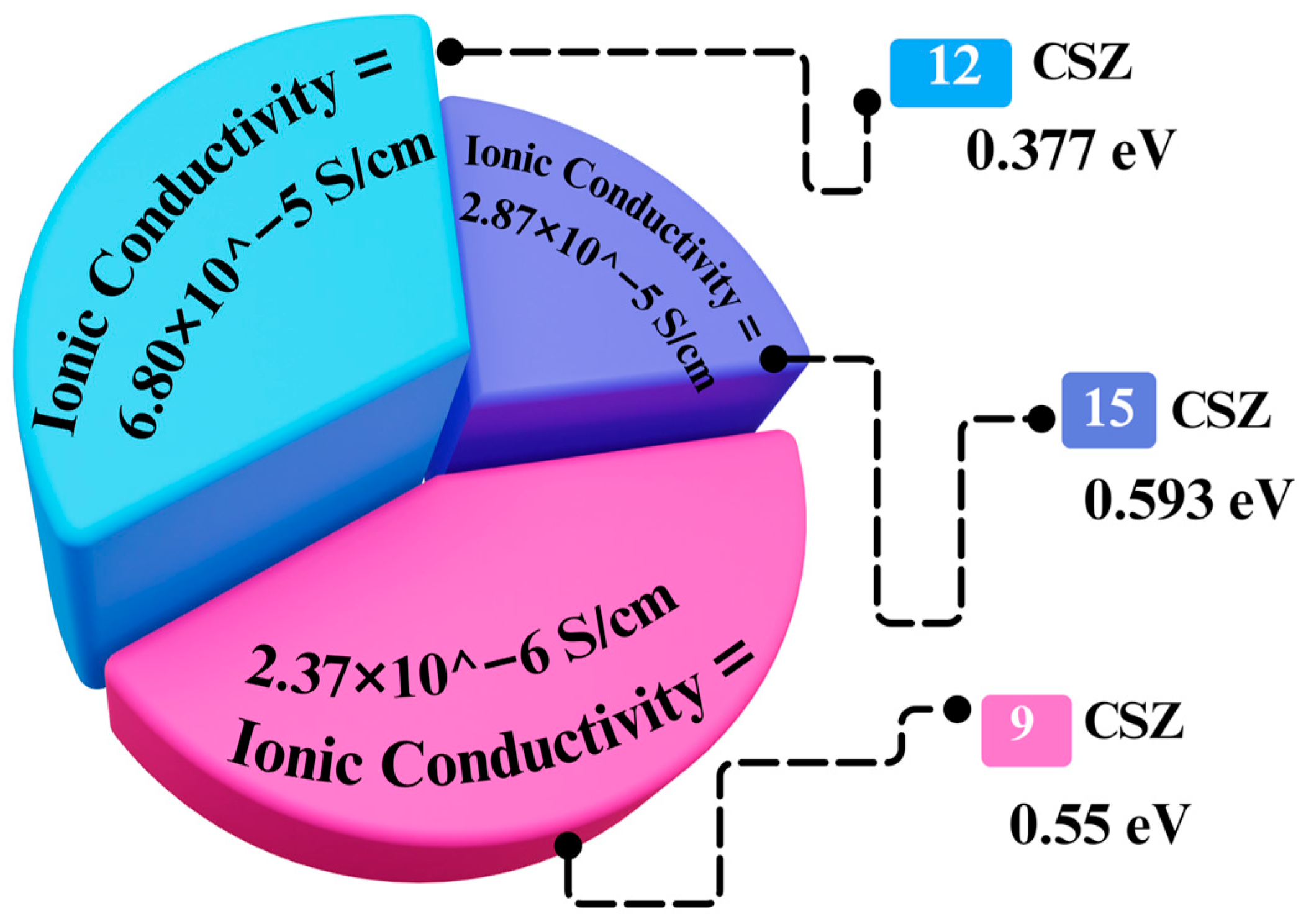
3.1. Calcia Stabilized Zirconia

3.1.1. The Reducibility Profile of Calcia Stabilized Zirconia

The reduction profile of a material is analyzed by H2-temperature-programmed reduction (H2-TPR). The hydrogen consumption over pure ZrO2 is due to the reduction of Zr4+ into Zr3+ and the formation of water [32]. The reduction profiles of Ca-, Mg-, Sc-, and Y-stabilized zirconia are entirely different than individual ZrO2 and CaO. The formation of a solid solution in stabilized zirconia is enriched with oxide vacancy. The hydrogen is activated by oxide vacancy, and activated hydrogen removes the nearby oxygen (besides the oxide vacancy) more efficiently. So, upon increasing doping concentration (up to 14 mol % MgO), oxide vacancy as well as H2 consumption are increased [32]. Ni-supported doped zirconia showed prominent reduction peaks for the reduction of NiO species. The reduction temperature for bulk NiO is 374 °C. Ni-containing doped ZrO2 catalyst showed a reduction peak at higher temperatures. It indicates the interaction of NiO with support [43]. If NiO is incorporated in the CaO–ZrO2 matrix by the co-precipitation method, it has a higher reduction temperature than the catalyst prepared by the impregnation method [44]. It indicates that NiO is in strong interaction if the catalyst was prepared by the co-precipitation method. The peak position changes depending on the extent of interaction of NiO with the support. The reduction temperature for CaZr1−xNixO3−δ catalyst was found to be higher than SrZr1−xNixO3−δ and BaZr1−xNixO3−δ, which indicates strong interaction of Ni with the support [45]. Here again, upon increasing the dopant amount, more oxide vacancy is formed. The oxide vacancy interacts strongly with the oxygen of NiO and makes the Ni–O bond weaker [32]. So, the reduction peak of NiO was shifted to a lower temperature upon increasing doping in ZrO2. As more oxide vacancy is formed, more oxygen (of NiO) interacts with oxide vacancy and more Ni-O bonds become weak and available for reduction with H2. Finally, a higher amount of H2 is consumed upon increasing doping in ZrO2.

3.1.2. Calcia Stabilized Zirconia-Based Support for Carrying Active Sites in DRM

Bellido et al. prepared calcium-stabilized zirconia support by polymerization method by using zirconium carbonate–nitric acid solution, calcium nitrate aqueous solution, and citric acid in ethylene glycol [32]. Finally, nickel nitrate aqueous solution is impregnated over the support. The properly dried and calcined material had a cubic NiO phase and tetragonal phase of CaO–ZrO2 solid solution. At up to 8 mol fraction of CaO, oxygen vacancy and NiO reducibility near the vacancy grew. After the reduction of this material, Ni supported over CaO–ZrO2 becomes ready for the catalytic reaction for the dry reforming of methane reaction. The CaO–ZrO2 Support possessed surface oxygen vacancies, which induced CO2 decomposition into activated oxygen, whereas CH4 is activated over metallic Ni. Finally, the reaction between activated oxygen and the activated CH4 pivots the path of dry reforming of methane. Ni supported over 8%CaO-92%ZrO2 (5Ni8CZ) catalyst converted CH4 and CO2 gas feed (in 1:1 ratio, total flow 60 mL/min) into syngas at 800 °C. A total of 70% CH4 conversion, 80% CO2 conversion, and 0.7 H2/CO ratio were achieved over 5Ni8CZ. Dama et al. prepared CaZr1−xNixO3−δ metal oxide matrix by the addition of corresponding metal nitrate–water solution to the citric acid solution at 80 °C, followed by drying and calcination [45]. CaZr1−xNixO3−δ had a higher dispersion of Ni and higher concentration of oxygen vacancy than “Ni supported over CaZrO3”. XRD confirmed the perovskite structural phase. The perovskite arrangement of the metal oxide matrix was capable of attaining 95% CH4 conversion and 96% CO2 conversion, and ~1 H2/CO ratio up to 500 h over an equimolar volume of CH4, CO2 and N2 gas feed.
Chen et al. prepared mesoporous Ni–CaO–ZrO2 nanocomposite catalysts through co-precipitation method by using nitrate precursor of Ni, Ca, Zr (in 0.4:0.2:1 mol ratio) at pH 7 and investigated it for dry reforming of methane over CO2 and CH4 (1.2:1) gas feed [43]. The catalyst has a stable tetragonal ZrO2 phase, and CaO induces a higher metal support interaction between Ni and ZrO2. The reduction of the catalyst resulted in structural collapse (resulting in a drop in surface area) and the formation of active sites Ni. During 100 h time on stream study, Ni–CaO–ZrO2 maintained 87% CH4 conversion (83% CO2 conversion) with 0.85 H2/CO at 850 °C and 73% CH4 conversion (67% CO2 conversion) with 0.78 H2/CO at 750 °C. The carbon deposition during the DRM became insignificant above 800 °C reaction temperature. Sun et al. found that Ni impregnated over CaO–ZrO2 had the presence of monoclinic ZrO2 phase whereas stable tetragonal ZrO2 phase prevails over co-precipitated Ni–CaO–ZrO2 nanocomposite (prepared at pH = 11–12) [44]. Co-precipitated catalyst attained higher surface area, stronger metal support interaction (between Ni and ZrO2) and higher dispersion of active sites “metallic Ni” (after reduction) than impregnated catalyst. Co-precipitated Ni–CaO–ZrO2 nanocomposite attained > 70% CH4 conversion, ~65% H2 yield, >80% CO2 conversion, and ~0.9 H2/CO up to 33 h at 700 °C. The catalytic activity for different times on stream over different calcium-stabilized zirconia catalysts towards DRM is summarized in Figure 6.

3.1.3. Calcia Stabilized Zirconia-Based Electrolyte for Fuel Cell

In solid oxide fuel cell (SOFC), the ion conductivity of zirconia is suggested to be enhanced when it is combined with other oxides. For this application, CaO (calcium oxide) is preferred over rare-earth oxide because of its lower price. When zirconia is doped with lower valent cation like Ca2+, higher valent Zr4+ is replaced and creates a pair of charge deficits inside the lattice, which will be overcome by the release of O2− ion, leaving an oxygen vacancy behind (Figure 7A). The CaSZ’s defect equation can also be shown by Kroeger–Vink notation (Equation (1)) [46]. Oxygen vacancy generation is the primary charge compensation process on doping with lower-valent cations, which is an implicit assumption in almost all investigations of CaSZ and related fluorite-structured solid solution materials. Overall, doping of Ca2+ brought greater oxide vacancy vis-a-vis conductivity of oxygen ions [47].
ZrO2
CaO → CaZr + V••O + OxO
where CaZr = Ca2+ in the Zr4+ lattice site, V••O = oxygen vacancy, OxO = lattice oxygen with a charge of zero.
Conductivity is much lower at the grain boundary than the bulk in high-purity ceramic [49,50]. In polycrystalline ceramics, the grain boundary is also a major factor in determining the material’s final conductivity [51]. However, at low as well as intermediate temperatures, it is generally accepted that the grain boundary’s influence on the conductivity is small. Calcium-stabilized zirconia (CaSZ) and other fluorite-based oxide ion conductors have gained much interest in their oxide ion conductivity [51]. It was found that the doping level of Ca should be optimum. At lower doping levels, migration of un-associated oxygen vacancies requires extra energy (than migration within the complex) and causes reduced conductivity. Again, at high doping concentrations, the Ca/oxygen association binds at the vacancy strongly. It reduces the carrier concentration and blocks the vacancy migration pathway partially [51] since ionic conductivity reaches its maximum at intermediate oxygen vacancy concentration [46].
The phase diagram for ZrO2–CaO is shown in Figure 7B, which includes both experimental data and computed findings. Four solid solution phases may be found in the ZrO2–CaO system: cubic (c), tetragonal (t), monoclinic (m), and periclase (p), and there are also four intermediate compounds: orthorhombic (o-CaZrO3), cubic (c-CaZrO3), CaZr4O9 (Phase 1; Ф1), and Ca6Zr19O44 (Phase 2; Ф2). Between 1135 and 1234 °C, phase 1 is stable, whereas between 1146 and 1352 °C, phase 2 is stable [52]. At the intermediate doping level of calcium in zirconia, the cubic zirconia phase is stable against high temperatures. Due to phase stabilization as well as higher oxygen ion conductivity, calcium-stabilized zirconia (CaSZ) as a solid electrolyte has been used widely.
Calcium-stabilized zirconia powders with compositions of 9, 12, and 15 mol% CaO were synthesized [18]. A compact and well-defined micro-structure was produced by sintering the green bodies by heating them at 1400 °C for 4 h. The 12 mol% CaO (in CaSZ) has a 21 nm grain size, which is mainly composed of the cubic phase. Small grains with greater concentrations of calcium oxide were found scattered along the structure’s grain boundaries. Impedance spectroscopy revealed that the 9 and 12 mol% CaO (in CaSZ) have a much lower resistance compared to the 15 mol% Ca in CaSZ. As the calcium ion concentration increases in calcium-stabilized zirconia, the material’s conductivity increases as well. 0.4–0.59 eV activation energy was calculated in 9–15% of calcium-stabilized zirconia [18].
In calcium-stabilized zirconia, the resistivity of both the bulk and the grain boundaries decreases as the temperature rises. The conductivity of the grain bulk and the grain boundary is increased with temperature along with the addition of calcium ions in zirconia. This is predictable because, to maintain the charge balance, oxygen ion vacancy is formed whenever a zirconium ion is exchanged for a calcium ion. Adding more calcium ions in the zirconia grain boundary would be thick and non-conductive, which would slow down the movement of oxygen ions across the grain boundary. The grain boundary conductivity paths are more spread out in the samples that have a lower calcium concentration. However, less calcium suggests the availability of fewer oxygen ion vacancies vis-à-vis less amount of charge carriers [53].
Electrolyte’s bulk conductivity decreases when the dopant amount is increased in CaSZ. However, their activation energy remains constant. Thus, the movement of oxygen vacancy or hopping controls the activation energy. The quantity of free oxygen vacancies, which falls significantly as the dopant increases, affects the conductivity of the electrolyte. CaSZ can be considered a weak electrolyte because 3% dopant shows a tiny fraction of the oxygen vacancies, which are free for movement in the electrolyte. At least in the low-temperature zone with linear Arrhenius behavior, the total amount of mobile vacancies does not change with CaO concentration (12, 15, or 18%).
The ionic conductivity and activation energy of different compositions of calcium-stabilized zirconia electrolytes at 500 °C working temperature are shown in Figure 8. It shows the variation of ionic conductivity with the doping concentration of calcium oxide. As dopant concentration increases from 9 to 15%, there is a noticeable rise in ionic conductivity, which indicates enhanced ion mobility at higher dopants. This trend is typical for ionic conductors, where oxygen vacancy helps to overcome potential barriers to ion migration. The activation energy provides insight into the energy required for ions to hop between sites. Lower activation energies suggest easier ion transport. Among electrolytes, 12 mol% CaSZ states high ionic conductivity (6.80 × 10⁻⁵ S/cm) with low activation energy (0.377 eV) [18].

3.2. Magnesium-Stabilized Zirconia

3.2.1. Reducibility Profile of Magnesium-Stabilized Zirconia

Under reductive treatment (in H2), ZrO2 is reduced. It was verified by Zr (3d) X-ray photoelectron spectroscopy (XPS) of fresh and reduced Ni/ZrO2 [54]. 182.3 and 184.6 eV binding energy were observed as Zr (3d5/2) and Zr (3d3/2) components in fresh catalysts. The binding energy was shifted to a lower value in the reduced catalyst system due to vacancies created by defect oxygen in the ZrO2 lattice. The reduction profile of 5 wt% Ni dispersed over Mg-stabilized ZrO2 is different than the rest of the doped ZrO2. MgO is a phase stabilizer for ZrO2 as well, as it forms a solid solution with NiO (as NiO.MgO) [55,56]. Solid solution binds NiO strongly. As a result, NiO’s reduction peak is shifted to a very high temperature upon the addition of Mg in the Ni/ZrO2 catalyst. Upon increasing Mg or Ni loading, a larger amount of solid solution was formed, and the reduction peak intensity/hydrogen consumption increased at high temperatures. In the XPS study also, the O (1 s) signal for Ni/ZrO2 was found at 529.8 eV, whereas over Ni/MgO, the O (1 s) signal was at 531.5 eV. It indicates the higher metal support interaction and higher basicity over oxygen [54,57] in the case of Ni/MgO.

3.2.2. Magnesium-Stabilized Zirconia-Based Support for Carrying Active Sites in DRM

The addition of 5 wt% NiO and 5 wt% MgO over ZrO2 by impregnation followed by mechanical mixing method (Ni is impregnated over ZrO2 then mechanical mixing of 5Ni/ZrO2 and MgO) was not found effective toward dry reforming of methane [58]. 5Ni5Mg/ZrO2 catalyst just showed ~20% CH4 conversion during 6.7 h reaction at 800 °C. Fatesh et al. introduced Mg and Ni over ZrO2 by sequential impregnation (impregnation of Mg precursor solution over ZrO2, then impregnation of Ni precursor over Mg/ZrO2) [56]. This material contained both monoclinic and tetragonal ZrO2 phases. Up to 3–5 wt % MgO loading, a NiO–MgO solid solution with strong interaction with support was recognized. These catalysts achieved more than 80% CH4 conversion (with ~1 H2/CO ratio) up to 8 h at 800 °C. Titus et al. prepared NiO–MgO–ZrO2 metal oxide matrixes by melt-impregnation techniques (Zr-hydroxide was added in the melt of Ni-nitrate and Mg-nitrate) [55]. Upon increasing Ni and Mg content in NiO–MgO–ZrO2, metal support interaction and the tetragonal ZrO2 phase grew. Up to 22 mol fraction of Ni, the catalyst performed constantly high (CH4 conversion ~90%) up to 15 h at 850 °C with low coking tendency.
Some other synthetic scheme was needed to explore the magnesia–zirconia-supported Ni catalyst towards DRM. Farooqi et al. incorporated up to 15 wt% zirconia with MgO through the precipitate method (at pH 9–10) and thereafter impregnated Ni over magnesia–zirconia support for the catalytic reaction. The incorporation of ZrO2 induced the NiO–MgO solid solution formation and dispersion of active sites “Ni”. The CH4 conversion over Ni/MgO-15ZrO2 was hiked to 60% (with 0.6 H2/CO) for 5 h at 800 °C [59]. The incorporation of MgO into zirconia through the coprecipitation method was found to stabilize the tetragonal phase of zirconia [57]. García et al. prepared MgO–ZrO2 support by the co-precipitation method, deposited Ni over by the wet impregnation method and investigated Ni/MgO–ZrO2 material for catalyzing dry reforming of methane reaction. The magnesia incorporation (0.4 wt%) resulted in the growth of basicity in MgO–ZrO2 metal oxide matrixes and increasing metal–support interaction. Ni-impregnated MgO (0.4 wt%)–ZrO2 showed ~25% CH4 conversion constantly up to 4.5 h at low temperature (600 °C). Kim et al. prepared a mesoporous Ni–MgO–ZrO2 catalyst by keeping the Ni amount constant (15 wt %) and varying the amount of MgO up to 50 wt% through the co-precipitation method [54]. The catalyst was investigated over coke oven gas (CH4: 27.0 vol%, CO2: 3.0 vol%, CO: 8.0 vol%, H2: 56.0 vol%, N2: 6.0 vol%) where CO2/CH4 had typical ratio of 1.2 and the CH4 from the feed gas may be oxidized by CO2 through dry reforming of methane reaction. The addition of MgO up to 30 wt% caused enhanced basicity, metal support interaction and Ni dispersion, but due to the formation of NiO–MgO solid solution, the reducibility of NiO was decreased. Overall, the total number of active sites (metallic Ni) was also found to be a maximum of over 30 wt% MgO content. Ni (15 wt%)–MgO (30 wt%)–ZrO2 catalyst showed ~70% CH4 conversion (H2/CO ~1.6) up to 50 h and ~65% CH4 conversion up to 150 h at 800 °C. Interestingly, the catalyst was found coke resistant as no graphitic, diamond, or amorphous type coke was evident in thermogravimetry and Raman analysis of spent catalysts. Nagaraja et al. incorporated K along with Ni–MgO–ZrO2 catalyst through co-precipitation method and found that uncalcined material showed better catalytic activity (>80% CH4 conversion up to 15 h at 750 °C) towards DRM than calcined catalyst [60]. Mg:Zr mole ratio of 5:2 (in Ni–MgO–ZrO2) showed best resistance to deactivation. The decremental effect of calcination towards DRM are argued by migration of Ni+2 into the bulk MgO layer may be speed up during the calcination step. The catalytic activity at different time on stream over different magnesia stabilized zirconia catalysts towards DRM is summarized in Figure 9.

3.2.3. Magnesia Stabilized Zirconia-Based Electrolyte

Ions in the FCC (face-centered fluorite) structure results in a defect structure characterized by disordered cations and irregularly distributed oxygen vacancies. Charge-wise, Mg+2 has the same charge as Ca+2, and so oxygen vacancy formation vis-à-vis ionic conductivity of MgSZ can be expected as in CaSZ (Figure 10A). The MgSZ’s defect equation can also be shown by Kroeger–Vink notation (Equation (2)) [46]. However, magnesium oxide has a significantly lower solid solution limit than calcium oxide, and MgSZ has a higher tolerance to thermal stress than CaSZ [61]. The ZrO2–MgO phase diagram is described in Figure 10B. At a temperature of 1400 °C and with a magnesium oxide concentration of 13 mol%, the tetragonal phase of magnesium oxide is formed during the eutectoid breakdown of the fluorite-type MgSZ solid solution. There is still a lack of clarity regarding the eutectoid reaction in the tetragonal phase at high temperatures, the solid solubility of magnesium oxide (MgO) in monoclinic zirconia (ZrO2), and the phase interface of a fluorite-type solid solution. It has been observed that fluorite-type Mg2Zr5O12 as well as metastable MgZr6O13 phases exist in the material [62].
ZrO2
MgO → MgZr + V••O + OxO
where, MgZr= Mg2+ in the Zr4+ lattice site, V••O = oxygen vacancy, OxO = lattice oxygen with a charge of zero [64].
The solid-state reaction approach was used to create compact magnesium-stabilized zirconia (MgSZ) ceramics having a wide variety of compositions. All samples consist of cubic, tetragonal, and monoclinic phases except 15MgSZ. Enhancing the MgO concentration in zirconia leads to a higher cubic content, which reaches a maximum of 15 mol% of magnesium oxide (MgO) and then decreases to nearly 20 mol% of magnesium oxide (MgO). 15MgSZ did not have a monoclinic phase. At temperatures between 1000 and 1200 °C, the breakdown of the cubic solid solution is responsible for the drop in the conductivity of Mg-partial stabilized zirconia (PSZ) specimens. Higher cubic content and rise in temperature have a synergistic impact on Mg-full stabilized zirconia (FSZ) samples, which causes a steady increase in their ionic conductivity. The conductivity of 9Mg-PSZ is better than 15Mg-FSZ between 1000 and 1350 °C because the defect associates may still bind large vacancies of oxygen; although at above 1350 °C, the impact of defect pairs is significantly decreased, and 15Mg-FSZ exhibits the highest conductivity. However, the breakdown of the cubic phase when cooling down at 1400 °C for Mg-PSZ samples as well as at below 1400 °C for Mg-FSZ samples is primarily responsible for the bending of the Arrhenius curves. Wen et al. synthesized CaO-Al2O3 coated magnesia stabilized zirconia [65]. The grain boundary conductivity of the bilayer systems increased exponentially with the increase in the CaO content. It resulted in an increase in total ionic conductivity (from 6.26 × 10⁻⁴ to 19.7 × 10⁻⁴ S/cm) upon increasing CaO content (from 22 wt% to 62 wt%) at a given temperature (850 °C) (Figure 11). Again, at a given CaO content; upon increasing temperature, the activation energy decreased, and the grain boundary/ionic conductivity was increased.

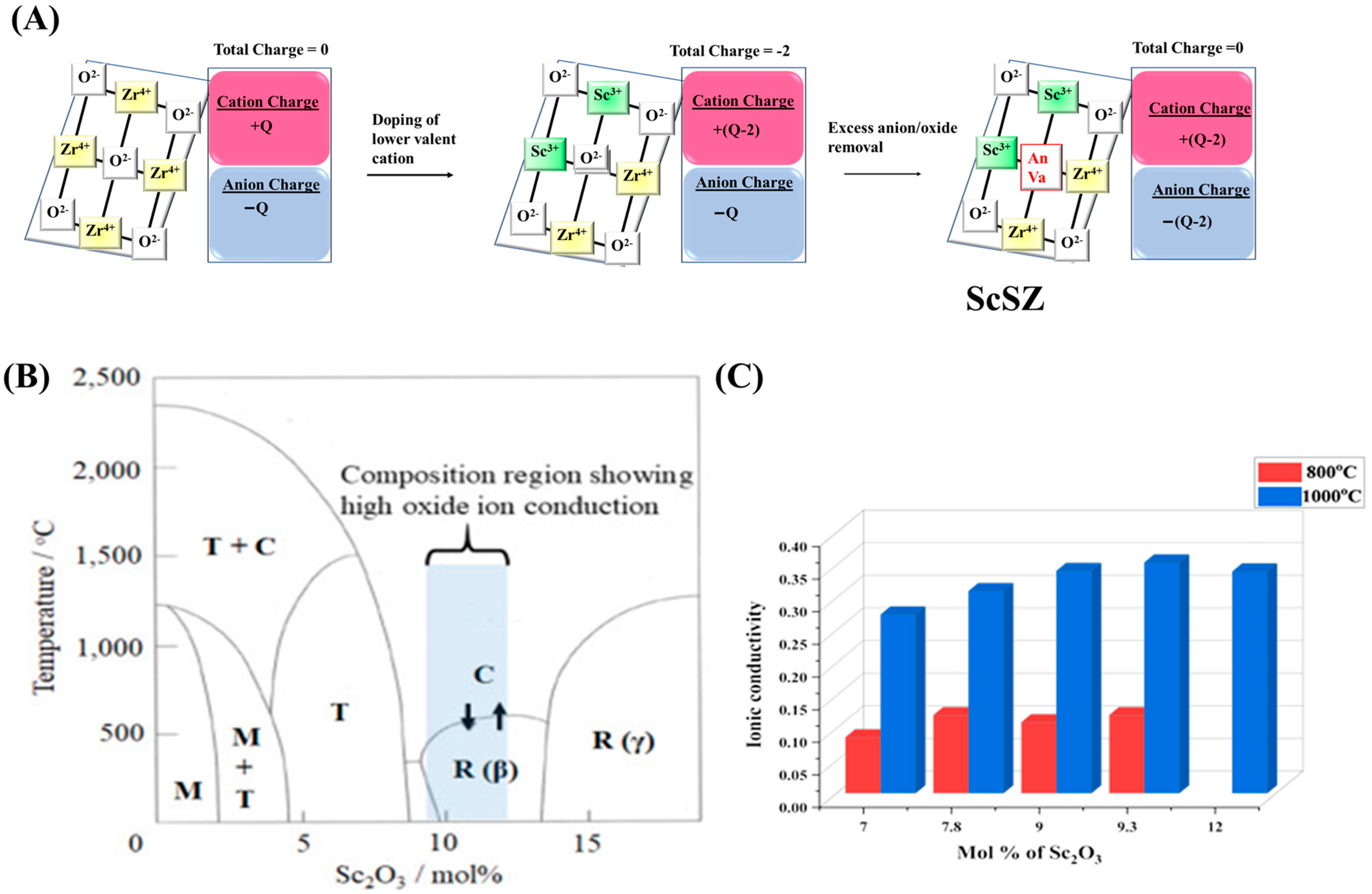
3.3. Scandia Stabilized Zirconia

3.3.1. Scandia Stabilized Zirconia-Based Support for Carrying Active Sites in DRM

Rajput et al. recently investigated “Scandia-ceria incorporated zirconia” (ScCeZr) support for carrying metallic Ni and Co (total 5 wt%) and its effective catalytic role towards dry reforming of methane [8]. The support was supplied by Daiichi Kigenso Kagaku Kogyo Co., Ltd. (Osaka, Japan) and it had 11% Sc2O3, 1.4% CeO2, and 87.6% ZrO2. Keeping a Ni/Co ratio of 3:1 over 10ScCeZr, the crystallinity of the sample was depleted. Ni-Co/10ScCeZr (Ni/Co = 3/1, total 5 wt%) had stable cubic ZrO2 phase, oxide ion conducting hexagonal Sc4Zr 3O 12 phase, and adequate oxygen vacancy, which remains consistent even after the DRM reaction. H2 yield over this catalytic material jumped from 46% to 79% upon raising the reaction temperature from 700 °C to 800 °C.

3.3.2. Scandia Stabilized Zirconia-Based Electrolyte

Classical molecular dynamics simulation showed that the bond lengths of the Sc–O and Zr–O bond lengths are similar [66]. The coordination numbers of Sc3+ and Zr4+ are smaller than the Y3+ coordination number at SOFC’s operating temperatures. An interesting method to enhance the ionic conductivity as well as chemical stability of zirconia-based electrolytes is the addition of scandium oxide (Sc2O3) in zirconium oxide (ZrO2) [67]. When zirconia is doped with a lower valent cation like Sc+3, higher valent Zr+4 is replaced and creates a charge deficit inside the lattice; such two doping sites generate a pair of charge deficits inside the lattice, which will be overcome by the release of O2− ion (Figure 12A). Isoelectric doping of zirconia with scandia yttria creates oxygen vacancies (V) to sustain charge balance and strong oxygen ion conductivity in ScSZ. The ScSZ’s defect equation can also be shown by Kroeger–Vink notation (Equation (3)) [68].
While working at low to moderate temperatures, the solid electrolyte scandia-stabilized zirconia (ScSZ) has strong ionic conductivity [69,70]. The utilization of ScSZ as an electrolyte in SOFCs has the potential to considerably decrease their working temperature. The Sc2O3 demonstrates that the cubic system with an ionic radius of Sc3+ is 0.81 Ǻ, which is similar when compared to the ionic radius of Zr4+ is 0.79 Ǻ at room temperature. This indicates why the ScSZ electrolyte has such a strong potential for being responded to as a solid electrolyte with strong ionic conductivity at lower working temperatures process to a wide extent [28,68]. A boost in oxygen vacancy due to the addition of scandia in zirconia reduces ohmic resistance and enhances oxygen ion flow throughout the solid electrolyte. Maintaining the solid structure of electrolytes with high density and ionic conductivity requires the optimal scandia (Sc2O3) amount for the formation of a stable cubic phase of the scandia-stabilized zirconia electrolyte (Figure 12B) [71]. Therefore, in order to create a phase equilibrium between the rhombohedral and the cubic phase in association with scandia (Sc2O3) and zirconia (ZrO2), the optimal concentration of Sc2O3 in ZrO2 is crucial. It was concluded that the rhombohedral phase structure would predominate at 10–15 mol% scandia (Sc2O3), and the cubic phase structure would predominate at 5–9 mol% scandia (Sc2O3) in zirconia (ZrO2) [72,73].
Figure 12. (A) Scheme of oxygen vacancy generation in scandia-stabilized zirconia. (B) Phase diagram of ScSZ reproduced with permission [74]. Copyright 2021, Elsevier. (C) The ionic conductivity of scandia-stabilized zirconia at 800 °C and 1000 °C.
Catalysts 15 00300 g012
ZrO2
Sc2O3 → 2ScZr + V••O + 3OxO
where, Sc′Zr = Sc3+ in the Zr4+ lattice site, V••O = oxygen vacancy, OxO = lattice oxygen with a charge of zero.
7.8 mol% of Sc2O3 in the ScSZ electrolyte exhibited strong ionic conductivity (0.31 S/cm) and a stable cubic phase at 1000 °C [75]. The impact in the formation of the cubic to rhombohedral phase transformation at low temperatures can be enhanced by the high insertion of the Sc2O3 content (i.e., 10–12 mol%). Rhombohedral phase shape leads to the breakdown of a solid electrolyte as it is inadequate for ionic movement, and finally, the conductivity of the ScSZ electrolyte is reduced [76].
For rare-earth oxide-stabilized zirconia (ZrO2), the maximum ionic conductivity is attained at temperatures of 1000 °C, and this shows the oxygen ion’s migrating and associating enthalpies as a function of dopant cation radius [77]. Between 800 and 1000 °C working temperature, conductivity increases upon incorporation of Sc (up to 9.3 mol%) into zirconia (Figure 12C). (ZrO2)0.922(Sc2O3)0.078 (represented as 7.8ScSZ) exhibited high ionic conductivity (0.120 S/cm) at 800 °C and 0.31 S/cm at at 1000 °C [75]. The ionic conductivity of (ZrO2)0.907(Sc2O3)0.093 (represented as 9.3ScSZ) was found to be 0.120 S/cm at 800 °C and 0.354 S/cm at 1000 °C, respectively. Lower activation energy generally correlates with higher ionic conductivity at a given temperature. For a given temperature 850 °C, the activation energy of 9.3ScSZ is lower (Ea = 68 kJ/mol) than 7.8ScSZ (Ea = 75 kJ/mol) [78] Upon further loading of Sc, the magnitude of ionic conductivity diminishes markedly. It can be attributed to the presence of local defect structures, which become dominant at such higher doping levels [79]. Zr0.09Sc0.10O1.95 showed 0.1 S/cm at 800 °C and 0.3 S/cm at 1000 °C [80]. However, further incorporation of 1 mol% Cr (by keeping Sc constant) into ScSZ induces the conversion of rhombohedral distorted fluorite phase into cubic one, which results in the rise of conductivity further [80].
The incorporation of 1 mol% CeO2 in 8–9 mol% Sc2O3–zirconia resulted in the stabilization of more conductive phases (cubic and tetragonal phases), suppression of low conductive phases (metastable tetragonal phases and rhombohedral phases) and overall higher conductivity (0.0167 S/cm) than 8–9 mol% Sc2O3–Zirconia [79]. The incorporation of Mn in scandia stabilized zirconia resulted in the suppression of cubic–rhombohedral phase transformation [81]. The material prepared by the conventional pechini method (PM) had a smaller mean particle diameter of 0.35 μm and a dense microstructure, whereas the sample prepared by ultrasonic spray pyrolysis (USP) had a porous microstructure with a larger mean particle diameter of 0.67 μm. MnScZr prepared by the PM method showed high conductivity of 0.074 S/cm and 0.112 S/cm at temperatures 750 °C and 800 °C, respectively [81].

3.4. Yttria Stabilized Zirconia

3.4.1. Reducibility Profile of Yttria Stabilized Zirconia

The formation of yttria–zirconia solid solution is facilitated by surface oxide enrichment and oxide vacancy. O (1 s) XPS spectra of “Ni dispersed over yttria-doped ZrO2” have one additional peak of about 537.7 eV than O (1 s) spectra of “Ni dispersed over ZrO2” [82]. It indicated the enrichment of the oxide layer over the surface upon incorporation of Y2O3 into ZrO2. Due to oxide enrichment, hydrogen consumption increases during reduction. Again, the oxide vacancy in the solid solution enables H2 to be removed nearby by oxygen (of the lattice) more easily, and H2 consumption is increased compared to that of individual metal oxides. Upon increasing Y2O3 (up to 8 mol%), both oxide vacancy and H2 consumption are increased [32]. Over Ni dispersed Y2O3–ZrO2, the reduction peak of NiO was also shifted to a lower temperature and H2 consumption was increased (than individual oxide) due to the weakening of the Ni–O bond by oxide vacancy of solid solution. Upon increasing the doping, this effect was more pronounced.

3.4.2. Yttria-Stabilized Zirconia-Based Support for Carrying Active Sites in DRM

The mechanical mixing of Y2O3 nanopowder (from Riedel–De Haen AG, Germany) with ZrO2 (Daiichi Kigenso Kagaku Kogyo Co., Ltd., Japan) was found to improve the surface area of the catalyst [83]. Both monoclinic and tetragonal ZrO2 phases are observed in XRD. The higher surface area gave more space for active sites “Ni” dispersion and provided better catalytic activity. A total of 5 wt% Ni dispersed over 10 wt% Y2O3–90 wt% ZrO2 (by impregnation method) gave the highest surface area as well as catalytic activity (58% CH4 conversion, 65% CO2 conversion during 7.3 h at 700 °C) towards DRM. Patel et al. [84] prepared yttria–zirconia support by mechanical mixing of 0–20 wt% Y2O3 with ZrO2, and then after 5 wt% Ni was added over Y2O3-ZrO2 by impregnation method. Upon increasing the loading of Y2O3 (up to 15 wt%), a tetragonal yttrium zirconium mixed oxide phase appeared, and the concentration of mobile lattice oxygen was increased, which resulted in efficient oxidation of carbon deposit during the DRM reaction. 5Ni/15Y2O3–85ZrO2 catalyst achieved ~65% H2 yield during 7 h at 700 °C. The H2 yield was further raised to 78% at 800 °C due to the endothermic nature of the DRM reaction. Bellido et al. employed 12 mol % Y2O3 for stabilization of ZrO2 and observed higher oxygen vacancy and higher edge of reducibility of NiO supported over “12 mol% Y2O3–88 mol % ZrO2” support (than lower loading of Y2O3) [32]. Oxide vacancy was the preferred site for CO2 activation, which oxidized the carbon deposit more effectively.
Mechanical mixing of 4 wt% Ba (by Ba-nitrate), 5 wt% Ni (by Ni-nitrate), 8 wt% Y2O3 and 92 wt% ZrO2 surged additional stable phases like BaZrO3 (along with cubic ZrO2) [85]. Barium addition also optimized the size of active sites “Ni” and improved the basicity/CO2 interaction. 5Ni4Ba/8Y2O3-92ZrO2 acquired ~79% H2 yield (H2/CO = 0.94) during 7 h at 800 °C. In the same way, Fakeeha et al. observed a stable mixed cubic zirconium gadolinium oxide phase and stable cubic Holmium zirconium oxide phase upon promotional addition of 4 wt% Gd and 4 wt% Ho, respectively [86]. The mixed oxide phase induced a stronger metal–support interaction, whereas Gd addition was also found to limit the Ni size up to 7.5 nm. 5Ni2Gd/8Y2O3-92ZrO2 and 5Ni4Ho/8Y2O3-92ZrO2 attained ~80% H2 yield and 84% H2 yield, respectively, towards DRM. Al-Zahrani et al. found that incorporating 1 wt% Cs over 5Ni/8Y2O3-92ZrO2 resulted in strong metal support interaction, >70% H2 yield and CH4 conversion (during 7 h at 800 °C) and strong resistance to the carbon deposit [87]. Chaudhary et al. impregnated 5 wt% Ni and 2 wt% ceria over “mechanically mixed 13 wt% Y2O3 and 77 wt % ZrO2” and observed stable cerium zirconium mixed oxide phases as well as exposed additional CH4 decomposition site at the interface of Ni and “Y2O3-ZrO2” [88]. Incorporation of 13 mol % ceria over yttria–zirconia (supplied by Tecnan-Nanomat S.L.; having 15 mol% Y2O3) through impregnation method and deposition of 14.6 wt% Ni over Ce/Y2O3-ZrO2 through impregnation method lead outstanding oxidative properly as well as strong metal support interaction [89]. This catalyst exhibited 100 CH4 conversion (H2/CO ~7.25) over CH4/CO2/He (4/4/92) gas feed over 120,000 cm3h−1g−1 space velocity and 750 °C temperature up to a 25-h time stream. Upon removing the carrier gas (CH4/CO2/He = 50/50/0) and increasing space velocity to 60,000 cm3h−1g−1), the catalyst activity dropped (~60% CH4 conversion) but remained constant up to 70 h. The catalytic activity up to different times on stream over different yttria–stabilized zirconia catalysts towards DRM is summarized in Figure 13.

3.4.3. Yttria Stabilized Zirconia-Based Electrolyte

Charge-wise doping of Y+3 into ZrO2 is similar to Sc+3 into ZrO2 (Figure 14A). So, vacancy formation and oxygen conductivity mechanisms seem to be similar. The YSZ’s defect Equation (4) can also be shown by Kroeger–Vink notation (Equation (4)) [90]. Scandium is relatively more costly than yttria. In high-temperature solid oxide fuel cell (SOFC) applications, yttria-stabilized zirconia (YSZ) is often employed as the solid electrolyte due to its excellent conductivity performance and great stability of chemical as well as mechanical resistance [91,92].
The phase diagram for the ZrO2−Y2O3 system is seen in Figure 14B [93,94]. At low temperatures, just one monoclinic ZrO2 phase exists when the Y2O3 concentration is even less than 1.5 mol%, but at high temperatures, a large tetragonal phase area exists. The proportion of cubic ZrO2 in the solid solution progressively rises when the Y2O3 concentration is greater than 1.5 mol%. With Y2O3 contents nearby 8 mol%, a highly stable ZrO2 solid solution is formed. As Y2O3 is dissolved in ZrO2, Y3+ cations migrate into the sites vacated by Zr4+ ions. At the same time, positively charged oxide vacancy is produced for each of the two yttrium (Y3+) ions that already exist.
Figure 14. (A) Scheme of oxygen vacancy generation in yttria-stabilized zirconia. (B) Phase diagram of yttria-stabilized zirconia (YSZ). M = Monoclinic, T = Tetragonal, C = Cubic Reproduced with permission [95]. Copyright 2018, Elsevier. (C) Ionic conductivity of yttria-stabilized zirconia 4.5, 8, and 10 YSZ. (D) Ionic conductivity of yttria-stabilized zirconia at 800 and 1000 °C.
Catalysts 15 00300 g014
ZrO2
Y2O3 → 2Y′Zr + V••O + 3OxO
where, Y′Zr = Y3+ in the Zr4+ lattice site, V••O = oxygen vacancy, OxO = lattice oxygen with a charge of zero [96].
At the low and intermediate working temperatures (400–800 °C) required for SOFCs, the YSZ electrolytes have poor conductivity. High operating temperatures are a problem for commercially used SOFCs, although this may be overcome by using a solid electrolyte that maintains acceptable conductivity at low to moderate working temperatures [97,98]. By decreasing the thickness of YSZ electrolyte from 100 μm to 10 μm, ohmic resistance is decreased, and oxygen ion movement increases, thus enhancing the ionic conductivity of SOFCs operating at low to moderate temperatures [26,99,100]. The addition of yttrium oxide (Y2O3) results in an elevated level of oxygen vacancies, which results in an improvement in the crystalline structure of the YSZ electrolyte, an increase in the mobility of oxygen ions within the YSZ electrolyte, and a reduction in the amount of energy loss because of the solid electrolyte’s reduced ohmic resistance [101,102]. In addition, zirconia’s chemical, as well as mechanical durability in a normal working environment was improved due to the addition of yttria, providing it with a suitable material for use in a high-performance electrochemical device [103,104]. These are the key reasons why YSZ electrolyte was one of the first solid electrolytes widely used in solid oxide fuel cells (SOFCs) [105]. Yet, the issue of cell degradation is brought into focus by the high working temperature of SOFCs (800–1000 °C), which is essential to attain high conductivity [106].
Xia et al. investigated the energy of the YSZ system through interatomic potential simulation techniques by using Mott–Littleton bulk calculations [90]. The lattice energy for the YSZ system is increased linearly with growing yttria contents. The conductivity profile of YSZ upon increasing loading of Y at different temperatures is shown in Figure 14C,D. The conductivity of the material is expected to increase with increasing temperature. 4.5YSZ, 8YSZ and 10YSZ shows 0.0000884 S/cm, 0.0000455 S/cm, and 0.0000167 S/cm conductivity, respectively, at 600 °C [107]. That means at a relatively lower working temperature (600 °C), ionic conductivity is found to decrease upon incorporation of a higher amount of yttria (4.5–10 mol%) into zirconia. However, at higher working temperatures (≥700 °C), intermediate loading of yttria (8 mol%) in zirconia has brought optimum conductivity. The ionic conductivity of 8YSZ steadily rises with temperature since no phase shift occurs throughout either process [64,108,109]. At 700 °C working temperature, the conductivity of 4.5YSZ, 8YSZ and 10YSZ is 0.000224 S/cm, 0.000274 S/cm, and 0.000197 S/cm, respectively [107]. In the same way, 8YSZ had a conductivity of 0.034 S/cm at 800 °C and 0.148 S/cm at 1000 °C, respectively [80]. Upon further loading yttria (10 mol %) into zirconia, the conductivity drops down to 0.024 S/cm at 800 °C and 0.1 S/cm at 1000 °C, respectively [80]. At high temperatures, the oxygen vacancies in the zirconia lattice become more mobile and can migrate to the yttria-doped regions. This migration of oxygen vacancies leads to the formation of yttria–zirconia clusters, which act as barriers to the movement of oxygen ions. Because of this, the material’s ionic conductivity goes down. In addition, the clustering of yttria ions can also contribute to the decrease in ionic conductivity. At high temperatures, the yttria ions can cluster together, forming larger particles that can block the movement of oxygen ions. This clustering effect is more pronounced in YSZ with higher yttria content, such as more than 8 mol% YSZ. Overall, the decrease in ionic conductivity of more than 8 mol% YSZ above 800 °C is due to the combined effects of oxygen vacancy migration and yttria clustering, which impede the movement of oxygen ions and reduce the material’s ionic conductivity. Figure 15 emphasizes the significant differences in ionic conductivity upon varying yttria concentrations (ranging from 2 mol% to 15 mol%) in YSZ at 800 °C. The highest conductivity in this series is observed for (ZrO2)0.92(Y2O3)0.08 with a value of 0.052 S/cm [75], while the lowest is for (ZrO2)0.85(Y2O3)0.15 at 0.006 S/cm [75]. This suggests an optimal yttria concentration (8%) for maximizing ionic conductivity, beyond which the conductivity decreases.
Recently, 2 to 4 nm monodispersed YSZ was synthesized with oleate groups (Oleate/metal = 1, 0.75 and 0.50) by hydrothermal method [110]. Despite high activation energy, it has 3.36–2.80 g/cm3 density, increased grain boundary volume, and 2.52–1.16 m S/cm ionic conductivity. Ryu et al. fabricate high-performance thin-film electrolytes via a sputtering process under 5, 10, and 15 mTorr pressure [111]. Under 15 mTorr sputtering chamber pressure, the YSZ exhibited the lowest ohmic resistance and maximum power density of 493 mW/cm2 at 500 °C (against 94.1 mW/cm2 at 5 mTorr).
Titania has extreme solubility with zirconia. However, the presence of more than one phase (cubic phase, ternary oxide phases like Y2Ti2O7 and ZrTiO4) leads to inferior conductivity. The incorporation of Cr in YSZ results in the formation of the solid solution of zirconia in chromium oxide. It results in enhanced electrical conductivity (0.011 S/cm at 700 °C and 0.13 S/cm at 1000 °C) over Zr0.09Y0.08Cr0.01O2−δ [80].
An 8 mol% yttria–92 mol% zirconia has 0.1 S/cm conductivity. On incorporating Sc2O3 till the yttria content remains rich, the composition is known as yttria-rich zirconia. At 1000 °C, conductivity in yttria-rich zirconia (having cubic phase) deteriorates due to precipitation of low conducting tetragonal-ZrO2 phase [112]. Upon Sc2O3, rich zirconia has a “dopant rich tetragonal phase (metastable tetragonal phase)”, and its conductivity also deteriorates with time at 1000 °C, due to decomposition of “dopant rich tetragonal phase” to “dopant rich cubic phase” and tetragonal-ZrO2 phase. However, the conductivity of scandia-rich zirconia was always higher (0.1 S/cm –0.16 S/cm) than yttria-stabilized zirconia. At higher mol %, Sc2O3 stabilized zirconia (up to 12.73 mol%) has low conductivity due to the growth of low conductive rhombohedral phase [112].
The addition of 9 mol% Sc2O3 into zirconia showed as high as 0.341 S/cm (0.306 S/cm after 5000 min) conductivity at 1000 °C measurement temperature [112,113]. On incorporating Y2O3 along with Sc2O3 into zirconia, Sc+3 is replaced by large Y+3 and provides steric hindrance to free migration of vacancies; it increases the activation energy and decreases the conductivity. The quantity of metastable phase also decreased with increasing incorporation of Y. Altogether; conductivity decreased monotonically with an increase in Y2O3 content. 6Sc3YZr, 3Sc6YZr, and 9YZr have conductivity of 0.246 S/cm (0.227 S/cm after 5000 min), 0.180 S/cm (0.169 S/cm after 5000 min), and 0.166 S/cm (0.163 S/cm after 5000 min) [113].
The conductivity of 8Sc1YbZr (tetragonal phase), 8Sc1YZr (tetragonal phase), and 9Sc1YZr (tetragonal and cubic phase) are very close to each other (~0.1 Scm−1) [114] at 900 °C. It was found that 1 mol%Yb2O3 addition stabilized the pseudocubic phase in a total 10 mol % metal oxide (as 9Sc1YbZr) and had the highest conductivity (0.21 S/cm) [114]. In the same way, 2 mol% Y2O3 or 2 mol% Yb2O3 incorporation stabilizes a single cubic phase in 10 mol% total metal oxide (as 8Sc2YZr and 8Sc2YbZr) and attains high conductivity.
Nowadays, by mathematical modelling using some datasets, the best results can be forecasted with a level of accuracy. Subramanian used support vector machine (SVM) learning to predict the maximum current density and power density of nickel oxide–samarium-doped ceria (NiO–SDC) composite anode, “lanthanum-strontium doped cobalt-iron oxide” (LSCF) cathode and yttrium stabilized zirconia electrolyte by using input of temperature (from 600 °C to 800 °C) and voltage (0.09 to 1.03 V) [115]. This model predicts 1160 mA cm2 maximum current density (against 1170 mA cm2 experimental figure) and a power density of 225 mW cm2 (against 227 mW cm2 experimental figure) at 800 °C temperature.
The comparison table for catalytic activity towards dry reforming of methane over Ni catalyst dispersed over Ca-, Mg-, Sc-, and Y-stabilized zirconia support is shown in Table S1. The conductivity value over different solid-state electrolytes made up of Ca-, Mg-, Sc-, and Y-Stabilized zirconia is presented in Table S2.

4. Discussion

Ni carrying over stabilized zirconia was populated with stable ZrO2 or mixed-ZrO2 phases, enriched with oxide vacancy and growing metal–support interaction. All, in turn, resulted in high-performance DRM catalyst. Ni is highly dispersed in the CaO–ZrO2 metal oxide matrix if it is prepared by the polymerization method. The specific perovskite composition CaZr1−xNixO3−δ, is quite stable and enriched with oxide vacancy and highly active (~95% CH4 conversion with ~1 H2/CO ratio up to 500 h reaction) toward DRM [32]. The melt impregnation of Ni and Mg nitrate over ZrO2 (up to 22 mol fraction of Ni) was found to grow the basic sites as well as stabilize the tetragonal phase of zirconia and endeavoring CH4 conversion about 90% up to 850 °C [55]. Ni and Co in 1:3 ratio over scandia-ceria incorporated zirconia was also found to generate stable cubic ZrO2 phase, and oxide ion conducting hexagonal Sc4Zr3O12 phase which achieved ~80% H2-yield up to 5 h of tested time on stream [8]. Gd-promoted Ni-based catalyst dispersed over 8 wt% Y2O3–92% ZrO2 had surged stable cubic zirconium gadolinium oxide phases, strong metal support interaction and activity as high as 80% up to 24 h [86]. It is observed that Ni supported over Sc-Yb-stabilized zirconia, Sc-Y-stabilized zirconia has not been investigated for DRM catalysis till now, which may be a potent catalyst for industrial application. Recently, Sc-Ce-stabilized zirconia has proved its potential in the mean of catalyst performance as well as cost [8].
Solid oxide fuel cells (SOFCs) have extremely high efficiently, low resistance to contamination, less cell impedance, and lower leakage of current than other fuel cells. The bottom-to-top approach of synthesis has precise control over the composition and size of SOFC material. The highly addressed SOFC research from high working temperature to low working temperature is presented in Figure 16A. Doped zirconia at high working temperature, doped ceria at intermediate working temperature, and doped ZnO/ZnO-composite at low working temperature are investigated in the development of SOFC (Figure 16A). The conductivity of oxide ions in the SOFC depends on a high concentration of oxide ion vacancy, less ohmic resistance, and a high population of ion conducting phases (Figure 16B). As per the “size fit” and “charge balance” of dopant metal, oxide vacancy is generated, which switches the ion diffusion mechanism.
Doping of zirconia with 12 mol% calcium stabilizes cubic zirconia phase, surges adequate concentration of oxygen ion vacancy/charge carriers, decreases the resistivity at both bulk and grain boundaries, and assures the highest oxygen ion conductivity (among rest calcium loading). Mg-stabilized zirconia (FSZ) as a dopant in zirconia induces higher tolerance to thermal stress than CaSZ. At 15 mol% MgO in ZrO2, cubic ZrO2 content rises, and it exhibits the highest conductivity (than other Mg loading) above 1350 °C. The extensive miscibility of scandia in zirconia decreases ohmic resistance and boosts oxygen vacancy. Especially at 9.3 mol % Sc2O3 in ScSZ electrolyte, the conductivity is nearly 0.354 S/cm at 1000 °C and 0.120 S/cm at 800 °C [75]. The higher concentration of Sc in ScSZ induces the transformation of cubic to unfavourable rhombohedral ZrO2 phase, resulting in lower conductivity. Cost-wise, Sc is also costly. Upon substituting the Sc with a larger Y+3, the quantity of metastable phase is decreased, ionic migration is sterically hindered, and conductivity decreases. Upon substituting Sc with Yb in ScSZ, the pseudocubic phase is stabilized and ensures high conductivity (0.21 S/cm over 9Sc1YbZr) [114]. The addition of 1 mol% Cr upon keeping Sc constant was found to escalate the conductivity by conversion of rhombohedral distorted phase into cubic one. In the same way, 1 mol% addition of Ce, more conductive phases appear, and low conductive phases are suppressed, which results in higher conductivity. Above 1.5 wt% Y in ZrO2, the cubic ZrO2 phase surges and at 8 mol% Y in ZrO2, a highly stable ZrO2 solid solution is formed. Again, by decreasing the thickness of YSZ electrolyte up to 10 μm, ohmic resistance is decreased, an elevated level of oxygen vacancy is formed, oxygen ion movement increases, and ionic conducitivyt is increased further [26]. More than 8 mol% Y loading leads to clustering of yttria and blocking of ionic movement. YSZ prepared by sputtering process under nTorr pressure has as high as 493 mW/cm2 power density at 500 °C [111]. Upon incorporating Sc and Y into ZrO2, the Sc2O3-rich ZrO2 has higher conductivity than yttria-stabilized ZrO2. 1 mol% Cr addition, while keeping Y constant, a solid solution is formed with 0.13 S/cm conductivity at 1000 °C [80].
DRM catalysts are in powder form and mostly made up of impregnation of Ni over doped ZrO2 support. The impregnated catalysts can be scaled up easily for large level production. However, scale-up of solid oxide electrolytes for large production needs additional manufacturing processes like mixing with solvent/binder, layer formation, and layer compaction [116]. The compatibility of solid oxide electrolytes with binders and solvents, interfacial contact between solid oxide electrolytes and electrolytes, and additional processing costs must be considered during large-scale manufacturing.

5. Conclusions and Future Prescriptive

The doped ZrO2 systems can be utilized as thermally stable support (for holding active site “Ni” for DRM reaction) as well as an ion-conducting medium (in solid oxide electrolyte). These two basic features of doped ZrO2 should be considered in the development of new doped ZrO2 for DRM catalytic and SOFC applications.

5.1. Doped ZrO2 as Thermally Stable Carrier

The role of support is to hold Ni’s active sites during a high-temperature DRM reaction. So, the support should be thermally stable. The ZrO2 and CaO–ZrO2 supports have an unstable monoclinic ZrO2 phase. However, at very high temperatures (2027 °C to 2227 °C) and intermediate CaO loading (20–40 mol fraction), a stable cubic ZrO2 phase is observed [48,52]. Interestingly, the incorporation of Ni in CaO–ZrO2 by co-precipitation method/polymerization method results in the formation of stable tetragonal phases [32,43]. Ni–MgO–ZrO2 system, tetragonal phases of ZrO2 are growing in the following order: sequential impregnation < melt impregnation < co-precipitation method. ZrO2 also forms stable phases with Y (tetragonal yttrium zirconium oxide), Ba (cubic barium zirconium oxide), Ho (cubic holmium zirconium oxide), Gd (cubic zirconium gadolinium oxide phase) [82]. Scandia-ceria incorporated zirconia had stable cubic ZrO2 phase and hexagonal Sc4Zr3O12 phase. These thermally stable phases of zirconia are suitable carriers for holding active sites “Ni” for DRM [117].

5.2. Doped ZrO2 as an Ion-Conducting Medium

The oxide vacancy is created as a result of charge deficit after doping and followed by oxide release as charge compensation (to maintain neutrality). The higher concentration of doping in ZrO2 creates more oxide vacancy vis-a-vis more bulk ion conductivity. The relation of conductivity (σ) and temperature (T) is expressed by σ = A/T exp(−Ea/KT) (where Ea is activation energy and “A” represents pre-exponential factor) [11]. However, the net electrical conductivity depends on other factors also, like grain boundary conductivity, generation of ion conducting phases, thickness/dispersion and clustering effect. For the development of new doped ZrO2 material, these phenomena should be clearly understandable.

5.2.1. Generation of Ion Conducting Phases

The tetragonal and rhombohedral ZrO2 phases are low-conducting phases, whereas the cubic ZrO2 phase is highly conducting phase [118]. The cubic phases of ZrO2 are increased up to the incorporation of 15 mol % MgO or 5–9 mol% of Sc2O3 or 8 mol % Y2O3. A higher population of cubic phase causes a rise in conductivity as well [76]. When cubic phases are broken down in a temperature range (1000–1200 °C) over 15MgSZ, the conductivity is decreased relatively [64]. Incorporation of 1 mol% Cr or Ce into ScSZ further restricts the cubic phase, resulting rise of conductivity and still higher Sc loading [80]. A total of 2 mol% Yb2O3 or 2 mol% Y2O3 addition to 8ScZr stabilized the pseudocubic phase or cubic phases, which resulted in higher conductivity and 9Sc1YbZr had attained highest conductivity [119]. Over higher Sc loading (10–12 mol %), the rhombohedral phase is built up, and the solid solution breaks resulting in inferior conductivity relatively.

5.2.2. Grain Boundary Conductivity

On higher doping of Ca (>15 mol %), the grain boundary becomes thicker where the non-conducting phase prevails, causing inferior conductivity. The conductivity of CaO-Al2O3 coated MgSZ is increased (than MgSZ) due to the rise of grain boundary conductivity [65]. The conductivity at the grain boundary is increased upon increasing the temperature (like bulk conductivity).

5.2.3. Thickness/Dispersion

By decreasing the thickness of YSZ (100 μm to 10 μm), creating a thin film (by applying 15mTorr pressure), increasing the dispersion of YSZ (2 to 4 nm size), ohmic resistance is decreased, and ionic conductivity is increased [26,99,100].

5.2.4. Clustering Effect

At higher concentrations of Y2O3 (>8 mol %) and higher temperatures (>800 °C), oxide vacancy migrates from ZrO2 to the Y2O3 region, which results in yttria clustering [75]. The clustering effect impedes oxide ions’ movement, resulting in inferior conductivity.
Overall for an application of support for Ni-based catalyst, doped ZrO2 material should have thermally stable phases like tetragonal and cubic phases. The conductivity of doped ZrO2 material is limited after a certain concentration of dopant. For example, the higher scandia doping caused the formation of non-conducting phases, whereas the higher doping of yttria in ZrO2 resulted in the association of point defects or the association of oxygen vacancies [120,121]. The doped ZrO2 should have an optimum concentration of doped metal oxide so that ion conducting phases like cubic phase, grain bulk conductivity, and grain boundary conductivity can be maximized, as well as the clustering effect can be minimized. The monodispersed distribution and thin film of doped ZrO2 material should also be considered to decrease ohmic resistance and increase ionic conductivity. Development of solid-state electrolytes at low working temperatures and low cost even now remains challenging.
Various computational tools like molecular dynamics calculation, density function theory, and artificial intelligence will be effective for forecasting the prediction about the properties of solid oxide fuel cells. Molecular dynamic calculations can predict preferential diffusion pathways of ions [122]. The ionic conductivity can be predicted by determining energy barriers through the climbing image nudged elastic band [123,124,125] in density function theory. Recently, machine learning was applied as a trustworthy tool for forecasting the ionic conductivity of new solid-state electrolytes by utilizing the characteristics of activation energy, operating temperature, lattice parameters, and unit cell volume [126].

Supplementary Materials

The following supporting information can be downloaded at https://www.mdpi.com/article/10.3390/catal15040300/s1, Table S1. Catalytic activity towards DRM reforming of methane over Ni catalyst dispersed over Ca-, Mg-, Sc-, Y-stabilized zirconia support, Table S2. Conductivity value over different solid-state electrolytes made up of Ca-, Mg-, Sc-, Y-stabilized zirconia.

Author Contributions

S.A.A.-Z.: Drafting synthetic strategy section, Y.R.: Conceptualization, Writing—original draft. K.J.C.: Writing stabilized zirconia for SOFC. A.S.A.-F.: Project administration, Funding acquisition, Writing—review and editing. F.A.A.A.: Drawing figures in Section 2. A.M.E.-T.: Drafting Introduction. A.A.M.A.: Drawing figures in Section 3. R.A.: Drafting Section 4. R.K.: Writing—review and editing. A.I.O.: Administration, Writing—review and editing., Writing—overview. All authors have read and agreed to the published version of the manuscript.

Funding

Researchers Supporting Project number (RSP2025R368), King Saud University.

Data Availability Statement

No data were used for the research described in the article.

Acknowledgments

The authors would like to extend their sincere appreciation to the Researchers Supporting Project number (RSP2025R368), King Saud University, Riyadh, Saudi Arabia. Y.S.R., K.J.C. and R.K. acknowledge Indus University (Ahmedabad, India) for supporting research.

Conflicts of Interest

The authors declare that they have no known competing financial interests or personal relationships that could have appeared to influence the work reported in this review paper.

References

  1. Alipour, Z.; Babu Borugadda, V.; Wang, H.; Dalai, A.K. Syngas Production through Dry Reforming: A Review on Catalysts and Their Materials, Preparation Methods and Reactor Type. Chem. Eng. J. 2023, 452, 139416. [Google Scholar] [CrossRef]
  2. Al-Fatesh, A.S.; Patel, N.; Fakeeha, A.H.; Alotibi, M.F.; Alreshaidan, S.B.; Kumar, R. Reforming of Methane: Effects of Active Metals, Supports, and Promoters. Catal. Rev. 2023, 66, 2209–2307. [Google Scholar] [CrossRef]
  3. Swaan, H.M.; Rouanet, R.; Widyananda, P.; Mirodatos, C. Partial Oxidation of Methane over Nickel- and Cobalt-Based Catalysts. In Natural Gas Conversion IV; de Pontes, M., Espinoza, R.L., Nicolaides, C.P., Scholtz, J.H., Scurrell, M.S., Eds.; Elsevier: Amsterdam, The Netherlands, 1997; Volume 107, pp. 447–453. ISBN 0167-2991. [Google Scholar]
  4. Gallego, G.S.; Batiot-Dupeyrat, C.; Barrault, J.; Florez, E.; Mondragón, F. Dry Reforming of Methane over LaNi1-YByO3±δ (B = Mg, Co) Perovskites Used as Catalyst Precursor. Appl. Catal. A Gen. 2008, 334, 251–258. [Google Scholar] [CrossRef]
  5. Ekeoma, B.C.; Yusuf, M.; Johari, K.; Abdullah, B. Mesoporous Silica Supported Ni-Based Catalysts for Methane Dry Reforming: A Review of Recent Studies. Int. J. Hydrogen Energy 2022, 47, 41596–41620. [Google Scholar] [CrossRef]
  6. Wischert, R.; Laurent, P.; Copéret, C.; Delbecq, F.; Sautet, P. γ-Alumina: The Essential and Unexpected Role of Water for the Structure, Stability, and Reactivity of “Defect” Sites. J. Am. Chem. Soc. 2012, 134, 14430–14449. [Google Scholar] [CrossRef]
  7. Fakeeha, A.H.; Patel, R.; El Hassan, N.; Al-Zahrani, S.A.; Al-Awadi, A.S.; Frusteri, L.; Bayahia, H.; Alharth, A.I.; Al-Fatesh, A.S.; Kumar, R. Holmium Promoted Yttria-Zirconia Supported Ni Catalyst for H2 Production via Dry Reforming of Methane. Int. J. Hydrogen Energy 2022, 47, 38242–38257. [Google Scholar] [CrossRef]
  8. Rajput, Y.B.; Al-Fatesh, A.S.; Osman, A.I.; Bayazed, M.O.; Ibrahim, A.A.; Fakeeha, A.H.; Abasaeed, A.E.; Almubaddel, F.S.; Alothman, O.; Kumar, R. Enhancing Hydrogen Production via Dry Reforming of Methane: Optimization of Co and Ni on Scandia-Ceria-Zirconia Supports for Catalytic Efficiency and Economic Feasibility. Fuel 2024, 378, 132843. [Google Scholar] [CrossRef]
  9. Alwadai, N.; Abahussain, A.A.M.; Shrivastava, V.K.; Al-zahrani, S.A.; Fakeeha, A.H.; Alarifi, N.; Bayazed, M.O.; Banabdwin, K.M.; Kumar, R.; Al-fatesh, A. The Synergistic Effect of Pore Architect and Reducibility in Ceria-Promoted Ni Molecular Sieve for Methane Dry Reforming. Catalysts 2024, 14, 852. [Google Scholar] [CrossRef]
  10. Hussain, S.; Yangping, L. Review of Solid Oxide Fuel Cell Materials: Cathode, Anode, and Electrolyte. Energy Transit. 2020, 4, 113–126. [Google Scholar]
  11. Zhang, J.; Lenser, C.; Menzler, N.H.; Guillon, O. Comparison of Solid Oxide Fuel Cell (SOFC) Electrolyte Materials for Operation at 500 °C. Solid State Ion. 2020, 344, 115138. [Google Scholar] [CrossRef]
  12. Laguna-Bercero, M.A. Recent Advances in High Temperature Electrolysis Using Solid Oxide Fuel Cells: A Review. J. Power Sources 2012, 203, 4–16. [Google Scholar] [CrossRef]
  13. Hajimolana, S.A.; Hussain, M.A.; Daud, W.M.A.W.; Soroush, M.; Shamiri, A. Mathematical Modeling of Solid Oxide Fuel Cells: A Review. Renew. Sustain. Energy Rev. 2011, 15, 1893–1917. [Google Scholar]
  14. Buonomano, A.; Calise, F.; d’Accadia, M.D.; Palombo, A.; Vicidomini, M. Hybrid Solid Oxide Fuel Cells-Gas Turbine Systems for Combined Heat and Power: A Review. Appl. Energy 2015, 156, 32–85. [Google Scholar]
  15. Mahato, N.; Banerjee, A.; Gupta, A.; Omar, S.; Balani, K. Progress in Material Selection for Solid Oxide Fuel Cell Technology: A Review. Prog. Mater. Sci. 2015, 72, 141–337. [Google Scholar]
  16. Wachsman, E.D.; Marlowe, C.A.; Lee, K.T. Role of Solid Oxide Fuel Cells in a Balanced Energy Strategy. Energy Environ. Sci. 2012, 5, 5498–5509. [Google Scholar] [CrossRef]
  17. Gómez, S.Y.; Hotza, D. Current Developments in Reversible Solid Oxide Fuel Cells. Renew. Sustain. Energy Rev. 2016, 61, 155–174. [Google Scholar]
  18. Kannan, M.; Singh, S.; Prasad, R.R. Oxide Ion Conductivity of Mechanically Produced Calcia Stabilised Zirconia for Oxygen Sensing Applications. Mater. Res. 2022, 25, e20220090. [Google Scholar] [CrossRef]
  19. Liu, Y.; Chen, Y.; Yu, H.; Guan, F.; Hou, Z.; Cui, D.; Zhang, Y. Bimetallic Ni-Co Catalysts for Co-Production of Methane and Liquid Fuels from Syngas. Catal. Today 2021, 369, 167–174. [Google Scholar] [CrossRef]
  20. Selvaraj, T.; Johar, B.; Khor, S.F. Iron/Zinc Doped 8 mol% Yttria Stabilized Zirconia Electrolytes for the Green Fuel Cell Technology: A Comparative Study of Thermal Analysis, Crystalline Structure, Microstructure, Mechanical and Electrochemical Properties. Mater. Chem. Phys. 2019, 222, 309–320. [Google Scholar] [CrossRef]
  21. Wang, C.; Wang, Y.; Chen, M.; Liang, D.; Yang, Z.; Cheng, W.; Tang, Z.; Wang, J.; Zhang, H. Recent Advances during CH4 Dry Reforming for Syngas Production: A Mini Review. Int. J. Hydrogen Energy 2021, 46, 5852–5874. [Google Scholar] [CrossRef]
  22. Parsa, M.; Qi, Y.; Di Nuzzo, J.J.; Moussakhani, Y.; Tirto, A.; Chaffee, A.L. Regenerable Carbon Honeycomb Monoliths Directly Prepared from Brown Coal: A Novel Carbon Product. Chem. Eng. J. 2023, 471, 144699. [Google Scholar] [CrossRef]
  23. Li, M.; Sun, Z.; Hu, Y.H. Catalysts for CO2 Reforming of CH4: A Review. J. Mater. Chem. A 2021, 9, 12495–12520. [Google Scholar] [CrossRef]
  24. Liang, F.; Yang, J.; Zhao, Y.; Zhou, Y.; Yan, Z.; He, J.; Yuan, Q.; Wu, J.; Liu, P.; Zhong, Z.; et al. A Review of Thin Film Electrolytes Fabricated by Physical Vapor Deposition for Solid Oxide Fuel Cells. Int. J. Hydrogen Energy 2022, 47, 36926–36952. [Google Scholar] [CrossRef]
  25. Ettalibi, O.; Samid, A.; Achak, O.; Mansori, M.; Chafik, T. Towards a Low-Cost Solid Oxide Electrolyte Based on Local Mineral. Mater. Chem. Phys. 2024, 315, 128949. [Google Scholar] [CrossRef]
  26. Zakaria, Z.; Abu Hassan, S.H.; Shaari, N.; Yahaya, A.Z.; Boon Kar, Y. A Review on Recent Status and Challenges of Yttria Stabilized Zirconia Modification to Lowering the Temperature of Solid Oxide Fuel Cells Operation. Int. J. Energy Res. 2020, 44, 631–650. [Google Scholar] [CrossRef]
  27. Capotondo, F.; Bishop, M.T.; Palmerini, F.; Smitshuysen, A.L.; Pirou, S.; Sudireddy, B.R.; Hagen, A. Fabrication Framework for Metal Supported Solid Oxide Cells via Tape Casting. J. Power Sources 2024, 613, 234812. [Google Scholar] [CrossRef]
  28. Zakaria, Z.; Kamarudin, S.K. Advanced Modification of Scandia-Stabilized Zirconia Electrolytes for Solid Oxide Fuel Cells Application—A Review. Int. J. Energy Res. 2021, 45, 4871–4887. [Google Scholar] [CrossRef]
  29. Irshad, M.; Siraj, K.; Raza, R.; Rafique, M.; Usman, M.; Ain, Q.u.; Ghaffar, A. Evaluation of Densification Effects on the Properties of 8 Mol % Yttria Stabilized Zirconia Electrolyte Synthesized by Cost Effective Coprecipitation Route. Ceram. Int. 2021, 47, 2857–2863. [Google Scholar] [CrossRef]
  30. De, S.; Zhang, J.; Luque, R.; Yan, N. Ni-Based Bimetallic Heterogeneous Catalysts for Energy and Environmental Applications. Energy Environ. Sci. 2016, 9, 3314–3347. [Google Scholar] [CrossRef]
  31. Courtin, E.; Boy, P.; Rouhet, C.; Bianchi, L.; Bruneton, E.; Poirot, N.; Laberty-Robert, C.; Sanchez, C. Optimized Sol-Gel Routes to Synthesize Yttria-Stabilized Zirconia Thin Films as Solid Electrolytes for Solid Oxide Fuel Cells. Chem. Mater. 2012, 24, 4540–4548. [Google Scholar] [CrossRef]
  32. Bellido, J.D.A.; De Souza, J.E.; M’Peko, J.-C.; Assaf, E.M. Effect of Adding CaO to ZrO2 Support on Nickel Catalyst Activity in Dry Reforming of Methane. Appl. Catal. A Gen. 2009, 358, 215–223. [Google Scholar] [CrossRef]
  33. Lai, Q.; Chen, J.; Chang, F.; Pei, J.; Liang, Y.; Chen, X.; Feng, Q.; Cen, Z.; Luo, N. Cold Sintering Process Assisted Sintering for 8YSZ Ceramic: A Way of Achieving High Density and Electrical Conductivity at a Reduced Sintering Temperature. Ceram. Int. 2023, 49, 14744–14749. [Google Scholar] [CrossRef]
  34. Garvie, R.C.; Hannink, R.H.; Pascoe, R.T. Ceramic Steel? Nature 1975, 258, 703–704. [Google Scholar] [CrossRef]
  35. Wongkamhaeng, K.; Dawson, D.V.; Holloway, J.A.; Denry, I. Effect of Surface Modification on In-Depth Transformations and Flexural Strength of Zirconia Ceramics. J. Prosthodont. 2019, 28, E364–E375. [Google Scholar] [CrossRef] [PubMed]
  36. Ferrage, L.; Bertrand, G.; Lenormand, P. Dense Yttria-Stabilized Zirconia Obtained by Direct Selective Laser Sintering. Addit. Manuf. 2018, 21, 472–478. [Google Scholar] [CrossRef]
  37. Zhang, N.; Asle Zaeem, M. Competing Mechanisms between Dislocation and Phase Transformation in Plastic Deformation of Single Crystalline Yttria-Stabilized Tetragonal Zirconia Nanopillars. Acta Mater. 2016, 120, 337–347. [Google Scholar] [CrossRef]
  38. Ghazanfari, A.; Li, W.; Leu, M.C.; Watts, J.L.; Hilmas, G.E. Additive Manufacturing and Mechanical Characterization of High Density Fully Stabilized Zirconia. Ceram. Int. 2017, 43, 6082–6088. [Google Scholar] [CrossRef]
  39. Singh, R.; Chavan, S.B. Processing and Properties of Scandia-Doped Zirconia Electrolyte for Intermediate Temperature SOFC. ECS Trans. 2007, 7, 2207–2212. [Google Scholar] [CrossRef]
  40. Haile, S.M. Fuel Cell Materials and Components. Acta Mater. 2003, 51, 5981–6000. [Google Scholar] [CrossRef]
  41. Stambouli, A.B.; Traversa, E. Solid Oxide Fuel Cells (SOFCs): A Review of an Environmentally Clean and Efficient Source of Energy. Renew. Sustain. Energy Rev. 2002, 6, 433–455. [Google Scholar]
  42. Etsell, T.H.; Flengas, S.N. The Electrical Properties of Solid Oxide Electrolytes. Chem. Rev. 1970, 70, 339–376. [Google Scholar] [CrossRef]
  43. Chen, Q.; Zhang, J.; Pan, B.; Kong, W.; Chen, Y.; Zhang, W.; Sun, Y. Temperature-Dependent Anti-Coking Behaviors of Highly Stable Ni-CaO-ZrO2 Nanocomposite Catalysts for CO2 Reforming of Methane. Chem. Eng. J. 2017, 320, 63–73. [Google Scholar] [CrossRef]
  44. Sun, N.; Wen, X.; Wang, F.; Peng, W.; Zhao, N.; Xiao, F.; Wei, W.; Sun, Y.; Kang, J. Catalytic Performance and Characterization of Ni–CaO–ZrO2 Catalysts for Dry Reforming of Methane. Appl. Surf. Sci. 2011, 257, 9169–9176. [Google Scholar] [CrossRef]
  45. Dama, S.; Ghodke, S.R.; Bobade, R.; Gurav, H.R.; Chilukuri, S. Active and Durable Alkaline Earth Metal Substituted Perovskite Catalysts for Dry Reforming of Methane. Appl. Catal. B Environ. 2018, 224, 146–158. [Google Scholar] [CrossRef]
  46. Dudek, M.; Bućko, M.M. Electrical Properties of Stoichiometric and Non-Stoichiometric Calcium Zirconate. In Proceedings of the Solid State Ionics, Kyoto, Japan, 9–13 November 2003; Volume 157. [Google Scholar]
  47. Mahato, N.; Gupta, A.; Balani, K. Doped Zirconia and Ceria-Based Electrolytes for Solid Oxide Fuel Cells: A Review. Nanomater. Energy 2012, 1, 27–45. [Google Scholar] [CrossRef]
  48. Wang, K.; Li, C.H.; Gao, Y.H.; Lu, X.G.; Ding, W.Z. Thermodynamic Reassessment of ZrO2-CaO System. J. Am. Ceram. Soc. 2009, 92, 1098–1104. [Google Scholar] [CrossRef]
  49. Li, K.; Chen, J.; Peng, J.; Koppala, S.; Omran, M.; Chen, G. One-Step Preparation of CaO-Doped Partially Stabilized Zirconia from Fused Zirconia. Ceram. Int. 2020, 46, 6484–6490. [Google Scholar] [CrossRef]
  50. Tong, X.; Bowman, W.J.; Mejia-Giraldo, A.; Crozier, P.A.; Mebane, D.S. New Data-Driven Interacting-Defect Model Describing Nanoscopic Grain Boundary Compositions in Ceramics. J. Phys. Chem. C 2020, 124, 23619–23625. [Google Scholar] [CrossRef]
  51. Ramírez-González, J.; West, A.R. Electrical Properties of Calcia-Stabilised Zirconia Ceramics. J. Eur. Ceram. Soc. 2020, 40, 5602–5611. [Google Scholar] [CrossRef]
  52. Liu, T.; Zhang, X.; Wang, X.; Yu, J.; Li, L. A Review of Zirconia-Based Solid Electrolytes. Ionics 2016, 22, 2249–2262. [Google Scholar]
  53. Prasad, R.R.; Yadav, K.L.; Puri, D.; Daniel, B.S.S. Conductivity Measurement of Calcia Stabilized Zirconia Prepared by Mechanical Route. Adv. Mater. Res. 2012, 585, 245–249. [Google Scholar]
  54. Kim, B.-J.; Park, H.-R.; Lee, Y.-L.; Ahn, S.-Y.; Kim, K.-J.; Hong, G.-R.; Roh, H.-S. Customized Ni-MgO-ZrO2 Catalysts for the Dry Reforming of Methane Using Coke Oven Gas: Optimizing the MgO Content. J. CO2 Util. 2023, 68, 102379. [Google Scholar] [CrossRef]
  55. Titus, J.; Roussière, T.; Wasserschaff, G.; Schunk, S.; Milanov, A.; Schwab, E.; Wagner, G.; Oeckler, O.; Gläser, R. Dry Reforming of Methane with Carbon Dioxide over NiO–MgO–ZrO2. Catal. Today 2016, 270, 68–75. [Google Scholar] [CrossRef]
  56. Al-Fatesh, A.S.; Kumar, R.; Fakeeha, A.H.; Kasim, S.O.; Khatri, J.; Ibrahim, A.A.; Arasheed, R.; Alabdulsalam, M.; Lanre, M.S.; Osman, A.I.; et al. Promotional Effect of Magnesium Oxide for a Stable Nickel-Based Catalyst in Dry Reforming of Methane. Sci. Rep. 2020, 10, 13861. [Google Scholar] [CrossRef] [PubMed]
  57. García, V.; Fernández, J.J.; Ruíz, W.; Mondragón, F.; Moreno, A. Effect of MgO Addition on the Basicity of Ni/ZrO2 and on Its Catalytic Activity in Carbon Dioxide Reforming of Methane. Catal. Commun. 2009, 11, 240–246. [Google Scholar] [CrossRef]
  58. Fakeeha, A.H.; Kurdi, A.; Al-Baqmaa, Y.A.; Ibrahim, A.A.; Abasaeed, A.E.; Al-Fatesh, A.S. Performance Study of Methane Dry Reforming on Ni/ZrO2 Catalyst. Energies 2022, 15, 3841. [Google Scholar] [CrossRef]
  59. Farooqi, A.S.; Abdullah, B.; Hasnain, S.M.W.; Farooqi, S.A. Syngas Production via Dry Reforming of Methane over Ni/MgO-ZrO2 Catalyst. IOP Conf. Ser. Earth Environ. Sci. 2023, 1261, 012028. [Google Scholar] [CrossRef]
  60. Nagaraja, B.M.; Bulushev, D.A.; Beloshapkin, S.; Chansai, S.; Ross, J.R.H. Potassium-Doped Ni–MgO–ZrO2 Catalysts for Dry Reforming of Methane to Synthesis Gas. Top. Catal. 2013, 56, 1686–1694. [Google Scholar] [CrossRef]
  61. Korotcenkov, G. Handbook of Gas Sensor Materials Properties, Advantages and Shortcomings for Applications Volume 1: Conventional Approaches; Springer: Berlin/Heidelberg, Germany, 2014; Volume 2. [Google Scholar]
  62. Banerjee, S.; Mukhopadhyay, P. Phase Transformations—Examples from Titanium and Zirconium Alloys; Elsevier: Amsterdam, The Netherlands, 2007; Volume 12. [Google Scholar]
  63. Hannink, R.; Swain, M.V. The Development of Zirconia Transformation Toughened Ceramics in Australia. J. Aust. Ceram. Soc. 2014, 50, 1–14. [Google Scholar]
  64. Deng, W.; Li, Y. High-Temperature Electrical Properties of Polycrystalline MgO-Doped ZrO2. Mater. Res. Bull. 2019, 113, 182–189. [Google Scholar] [CrossRef]
  65. Wen, T.; Jin, E.; Yuan, L.; Yu, J.; Zhou, Y.; Tian, C. Structure and Ionic Conductivity of ZrO2 (MgO)/CaO-Al2O3 Bilayer System Used as Solid Electrolyte for Sulfur Sensor. Mater. Res. Bull. 2019, 117, 113–119. [Google Scholar]
  66. Devanathan, R.; Thevuthasan, S.; Gale, J.D. Defect Interactions and Ionic Transport in Scandia Stabilized Zirconia. Phys. Chem. Chem. Phys. 2009, 11, 5506–5511. [Google Scholar] [CrossRef]
  67. Hansen, K.K. Solid State Electrochemical DeNOx-An Overview. Appl. Catal. B Environ. 2010, 100, 427–432. [Google Scholar] [CrossRef]
  68. Valadez Huerta, G.; Reus, L.; Kabelac, S. A Diffusivity Study of (Sc2O3)0.1(CeO2)0.01(ZrO2)0.89 between 1100 and 1500 K at Zero Pressure with Molecular Dynamics. J. Chem. Eng. Data 2018, 63, 1955–1960. [Google Scholar] [CrossRef]
  69. Mahmud, L.S.; Muchtar, A.; Somalu, M.R. Challenges in Fabricating Planar Solid Oxide Fuel Cells: A Review. Renew. Sustain. Energy Rev. 2017, 72, 105–116. [Google Scholar]
  70. Dwivedi, S. Solid Oxide Fuel Cell: Materials for Anode, Cathode and Electrolyte. Int. J. Hydrogen Energy 2020, 45, 23988–24013. [Google Scholar] [CrossRef]
  71. Spirin, A.; Ivanov, V.; Nikonov, A.; Lipilin, A.; Paranin, S.; Khrustov, V.; Spirina, A. Scandia-Stabilized Zirconia Doped with Yttria: Synthesis, Properties, and Ageing Behavior. Solid State Ionics 2012, 225, 448–452. [Google Scholar]
  72. Yamamoto, O.; Arati, Y.; Takeda, Y.; Imanishi, N.; Mizutani, Y.; Kawai, M.; Nakamura, Y. Electrical Conductivity of Stabilized Zirconia with Ytterbia and Scandia. Solid State Ionics 1995, 79, 137–142. [Google Scholar] [CrossRef]
  73. Chowdari, B.V.R.; Dissanayake, M.A.K.L.; Careem, M.A. Solid State Ionics: New Developments. In Proceedings of the Fifth Asian Conference on Defence Technology, Hsinchu, Taiwan, 20–22 November 1996. [Google Scholar]
  74. Nakayama, S.; Tokunaga, R.; Takata, M.; Kondo, S.; Nakajima, Y. Crystal Phase, Electrical Properties, and Solid Oxide Fuel Cell Electrolyte Application of Scandia-Stabilized Zirconia Doped with Rare Earth Elements. Open Ceram. 2021, 6, 100136. [Google Scholar] [CrossRef]
  75. Badwal, S.P.S.; Ciacchi, F.T. Oxygen-Ion Conducting Electrolyte Materials for Solid Oxide Fuel Cells. Ionics 2000, 6, 1–21. [Google Scholar]
  76. Palaci, Y.; Timurkutluk, B. Design and Fabrication of Stair-Step-Type Electrolyte Structure for Solid Oxide Fuel Cells. Int. J. Energy Res. 2013, 37, 631–637. [Google Scholar] [CrossRef]
  77. Yamamoto, O.; Arachi, Y.; Sakai, H.; Takeda, Y.; Imanishi, N.; Mizutani, Y.; Kawai, M.; Nakamura, Y. Zirconia Based Oxide Ion Conductors for Solid Oxide Fuel Cells. Ionics 1998, 4, 403–408. [Google Scholar] [CrossRef]
  78. Badwal, S.P.S.; Ciacchi, F.T.; Milosevic, D. Scandia–Zirconia Electrolytes for Intermediate Temperature Solid Oxide Fuel Cell Operation. Solid State Ion. 2000, 136–137, 91–99. [Google Scholar] [CrossRef]
  79. Kumar, A.; Jaiswal, A.; Sanbui, M.; Omar, S. Oxygen-Ion Conduction in Scandia-Stabilized Zirconia-Ceria Solid Electrolyte (XSc2O3–1CeO2–(99−x)ZrO2, 5 ≤ x ≤ 11). J. Am. Ceram. Soc. 2017, 100, 659–668. [Google Scholar] [CrossRef]
  80. Kharton, V.V.; Naumovich, E.N.; Vecher, A.A. Research on the Electrochemistry of Oxygen Ion Conductors in the Former Soviet Union. I. ZrO2-Based Ceramic Materials. J. Solid State Electrochem. 1999, 3, 61–81. [Google Scholar] [CrossRef]
  81. Choi, Y.H.; Lee, S.H.; Wackerl, J.; Jung, D.H.; Suhr, D.S.; Choi, S.Y.; Peck, D.H. Fabrication of Scandia-Stabilized Zirconia Electrolyte with a Porous and Dense Composite Layer for Solid Oxide Fuel Cells. Ceram. Int. 2012, 38, S485–S488. [Google Scholar]
  82. Tillborg, H.; Nilsson, A.; Hernnäs, B.; Mårtensson, N.; Palmer, R.E. X-Ray and UV Photoemission Studies of Mono-, Bi- and Multilayers of Physisorbed Molecules: O2 and N2 on Graphite. Surf. Sci. 1993, 295, 1–12. [Google Scholar] [CrossRef]
  83. Ibrahim, A.A.; Kasim, S.O.; Fakeeha, A.H.; Lanre, M.S.; Abasaeed, A.E.; Abu-Dahrieh, J.K.; Al-Fatesh, A.S. Dry Reforming of Methane with Ni Supported on Mechanically Mixed Yttria-Zirconia Support. Catal. Lett. 2022, 152, 3632–3641. [Google Scholar] [CrossRef]
  84. Patel, R.; Fakeeha, A.H.; Kasim, S.O.; Sofiu, M.L.; Ibrahim, A.A.; Abasaeed, A.E.; Kumar, R.; Al-Fatesh, A.S. Optimizing Yttria-Zirconia Proportions in Ni Supported Catalyst System for H2 Production through Dry Reforming of Methane. Mol. Catal. 2021, 510, 111676. [Google Scholar] [CrossRef]
  85. Al-Fatesh, A.S.; Patel, R.; Srivastava, V.K.; Ibrahim, A.A.; Naeem, M.A.; Fakeeha, A.H.; Abasaeed, A.E.; Alquraini, A.A.; Kumar, R. Barium-Promoted Yttria–Zirconia-Supported Ni Catalyst for Hydrogen Production via the Dry Reforming of Methane: Role of Barium in the Phase Stabilization of Cubic ZrO2. ACS Omega 2022, 7, 16468–16483. [Google Scholar] [CrossRef]
  86. Fakeeha, A.H.; Al-Fatesh, A.S.; Srivastava, V.K.; Ibrahim, A.A.; Abahussain, A.A.M.; Abu-Dahrieh, J.K.; Alotibi, M.F.; Kumar, R. Hydrogen Production from Gadolinium-Promoted Yttrium-Zirconium-Supported Ni Catalysts through Dry Methane Reforming. ACS Omega 2023, 8, 22108–22120. [Google Scholar] [CrossRef] [PubMed]
  87. Al-Zahrani, S.A.; Al-Fatesh, A.S.; Kaydouh, M.-N.; Al Otaibi, A.; Francesco, F.; Fakeeha, A.H.; El Hassan, N. High Carbon-Resistant Nickel Supported on Yttria–Zirconia Catalysts for Syngas Production by Dry Reforming of Methane: The Promoting Effect of Cesium. Alex. Eng. J. 2023, 74, 371–386. [Google Scholar] [CrossRef]
  88. Chaudhary, M.L.; Al-Fatesh, A.S.; Kumar, R.; Lanre, M.S.; Frusteri, F.; AlReshaidan, S.B.; Ibrahim, A.A.; Abasaeed, A.E.; Fakeeha, A.H. Promotional Effect of Addition of Ceria over Yttria-Zirconia Supported Ni Based Catalyst System for Hydrogen Production through Dry Reforming of Methane. Int. J. Hydrogen Energy 2022, 47, 20838–20850. [Google Scholar] [CrossRef]
  89. Muñoz, M.A.; Calvino, J.J.; Rodríguez-Izquierdo, J.M.; Blanco, G.; Arias, D.C.; Pérez-Omil, J.A.; Hernández-Garrido, J.C.; González-Leal, J.M.; Cauqui, M.A.; Yeste, M.P. Highly Stable Ceria-Zirconia-Yttria Supported Ni Catalysts for Syngas Production by CO2 Reforming of Methane. Appl. Surf. Sci. 2017, 426, 864–873. [Google Scholar] [CrossRef]
  90. Xia, X.; Oldman, R.; Catlow, R. Computational Modeling Study of Bulk and Surface of Yttria-Stabilized Cubic Zirconia. Chem. Mater. 2009, 21, 3576–3585. [Google Scholar] [CrossRef]
  91. Jiao, Z.; Shikazono, N. 3D Reconstruction Size Effect on the Quantification of Solid Oxide Fuel Cell Nickel–Yttria-Stabilized-Zirconia Anode Microstructural Information Using Scanning Electron Microscopy-Focused Ion Beam Technique. Sci. Bull. 2016, 61, 1317–1323. [Google Scholar] [CrossRef]
  92. Phongpreecha, T.; Nicholas, J.D.; Bieler, T.R.; Qi, Y. Computational Design of Metal Oxides to Enhance the Wetting and Adhesion of Silver-Based Brazes on Yttria-Stabilized-Zirconia. Acta Mater. 2018, 152, 229–238. [Google Scholar] [CrossRef]
  93. Asadikiya, M.; Sabarou, H.; Chen, M.; Zhong, Y. Phase Diagram for a Nano-Yttria-Stabilized Zirconia System. RSC Adv. 2016, 6, 17438–17445. [Google Scholar] [CrossRef]
  94. Nowotny, J.; Bak, T.; Nowotny, M.K.; Sorrell, C.C. Charge Transfer at Oxygen/Zirconia Interface at Elevated Temperatures Part 1: Basic Properties and Terms. Adv. Appl. Ceram. 2005, 104, 147–153. [Google Scholar] [CrossRef]
  95. Ren, X.; Zhao, M.; Feng, J.; Pan, W. Phase Transformation Behavior in Air Plasma Sprayed Yttria Stabilized Zirconia Coating. J. Alloys Compd. 2018, 750, 189–196. [Google Scholar] [CrossRef]
  96. Celik, E.; Negi, R.S.; Bastianello, M.; Boll, D.; Mazilkin, A.; Brezesinski, T.; Elm, M.T. Tailoring the Protonic Conductivity of Porous Yttria-Stabilized Zirconia Thin Films by Surface Modification. Phys. Chem. Chem. Phys. 2020, 22, 11519–11528. [Google Scholar] [CrossRef] [PubMed]
  97. Mat, Z.B.A.; Madya; Kar, Y.B.; Hassan, S.H.B.A.; Talik, N.A.B. Proton Exchange Membrane (PEM) and Solid Oxide (SOFC) Fuel Cell Based Vehicles-a Review. In Proceedings of the 2017 2nd IEEE International Conference on Intelligent Transportation Engineering, ICITE 2017, Singapore, 1–3 September 2017. [Google Scholar]
  98. Santos, T.H.; Grilo, J.P.F.; Loureiro, F.J.A.; Fagg, D.P.; Fonseca, F.C.; Macedo, D.A. Structure, Densification and Electrical Properties of Gd3+ and Cu2+ Co-Doped Ceria Solid Electrolytes for SOFC Applications: Effects of Gd2O3 Content. Ceram. Int. 2018, 44, 2745–2751. [Google Scholar] [CrossRef]
  99. Shri Prakash, B.; Senthil Kumar, S.; Aruna, S.T. Properties and Development of Ni/YSZ as an Anode Material in Solid Oxide Fuel Cell: A Review. Renew. Sustain. Energy Rev. 2014, 36, 149–179. [Google Scholar]
  100. Saebea, D.; Authayanun, S.; Patcharavorachot, Y.; Chatrattanawet, N.; Arpornwichanop, A. Electrochemical Performance Assessment of Low-Temperature Solid Oxide Fuel Cell with YSZ-Based and SDC-Based Electrolytes. Int. J. Hydrogen Energy 2018, 43, 921–931. [Google Scholar] [CrossRef]
  101. Vonk, V.; Khorshidi, N.; Stierle, A.; Dosch, H. Atomic Structure and Composition of the Yttria-Stabilized Zirconia (111) Surface. Surf. Sci. 2013, 612, 69–76. [Google Scholar] [CrossRef] [PubMed]
  102. Zuo, K.H.; Zeng, Y.P.; Jiang, D. Properties of Microstructure-Controllable Porous Yttria-Stabilized Ziroconia Ceramics Fabricated by Freeze Casting. Int. J. Appl. Ceram. Technol. 2008, 5, 198–203. [Google Scholar] [CrossRef]
  103. Della Negra, M.; Foghmoes, S.P.V.; Klemensø, T. Complementary Analysis Techniques Applied on Optimizing Suspensions of Yttria Stabilized Zirconia. Ceram. Int. 2016, 42, 14443–14451. [Google Scholar] [CrossRef]
  104. Bae, K.; Son, K.S.; Kim, J.W.; Park, S.W.; An, J.; Prinz, F.B.; Shim, J.H. Proton Incorporation in Yttria-Stabilized Zirconia during Atomic Layer Deposition. Int. J. Hydrogen Energy 2014, 39, 2621–2627. [Google Scholar] [CrossRef]
  105. Marinopoulos, A.G. Protons in Cubic Yttria-Stabilized Zirconia: Binding Sites and Migration Pathways. Solid State Ionics 2018, 315, 116–125. [Google Scholar] [CrossRef]
  106. Singhal, S.C. Solid Oxide Fuel Cells for Stationary, Mobile, and Military Applications. Solid State Ionics 2002, 152–153, 405–410. [Google Scholar] [CrossRef]
  107. Rahmawati, F.; Permadani, I.; Syarif, D.G.; Soepriyanto, S. Electrical Properties of Various Composition of Yttrium Doped-Zirconia Prepared from Local Zircon Sand. Int. J. Technol. 2017, 8, 939. [Google Scholar] [CrossRef]
  108. Jiang, L.; Guo, S.; Bian, Y.; Zhang, M.; Ding, W. Effect of Sintering Temperature on Mechanical Properties of Magnesia Partially Stabilized Zirconia Refractory. Ceram. Int. 2016, 42, 10593–10598. [Google Scholar] [CrossRef]
  109. Muccillo, E.N.S.; Kleitz, M. Impedance Spectroscopy of Mg-Partially Stabilized Zirconia and Cubic Phase Decomposition. J. Eur. Ceram. Soc. 1996, 16, 453–465. [Google Scholar] [CrossRef]
  110. Makinose, Y.; Yamada, T.; Kubota, Y. Ionic Conductivity of Electrolytes Composed of Oleate-Capped Yttria-Stabilized Zirconia Nanoparticles. ACS Omega 2023, 8, 48728–48734. [Google Scholar] [CrossRef] [PubMed]
  111. Ryu, S.; Choi, I.W.; Kim, Y.J.; Lee, S.; Jeong, W.; Yu, W.; Cho, G.Y.; Cha, S.W. Nanocrystal Engineering of Thin-Film Yttria-Stabilized Zirconia Electrolytes for Low-Temperature Solid-Oxide Fuel Cells. ACS Appl. Mater. Interfaces 2023, 15, 42659–42666. [Google Scholar] [CrossRef] [PubMed]
  112. Ciacchi, F.T.; Badwal, S.P.S. The System Y2O3-Sc2O3-ZrO2: Phase Stability and Ionic Conductivity Studies. J. Eur. Ceram. Soc. 1991, 7, 197–206. [Google Scholar] [CrossRef]
  113. Badwal, S.P.S.; Ciacchi, F.T.; Rajendran, S.; Drennan, J. An Investigation of Conductivity, Microstructure and Stability of Electrolyte Compositions in the System 9 Mol% (Sc2O3-Y2O3)-ZrO2(Al2O3). Solid State Ionics 1998, 109, 167–186. [Google Scholar] [CrossRef]
  114. Agarkov, D.A.; Borik, M.A.; Bredikhin, S.I.; Burmistrov, I.N.; Eliseeva, G.M.; Kulebyakin, A.V.; Kuritsyna, I.E.; Lomonova, E.E.; Milovich, F.O.; Myzina, V.A.; et al. Phase Compositions, Structures and Properties of Scandia-Stabilized Zirconia Solid Solution Crystals Co-Doped with Yttria or Ytterbia and Grown by Directional Melt Crystallization. Solid State Ionics 2020, 346, 115218. [Google Scholar] [CrossRef]
  115. Subramanian, Y.; Veena, R.; Ali, S.A.M.; Kumar, A.; Gubediran, R.K.; Dhanasekaran, A.; Gurusamy, D.; Muniandi, K. Artificial Intelligence Technique Based Performance Estimation of Solid Oxide Fuel Cells. Mater. Today Proc. 2023, 80, 2573–2576. [Google Scholar]
  116. Minkiewicz, J.; Jones, G.M.; Ghanizadeh, S.; Bostanchi, S.; Wasely, T.J.; Yamini, S.A.; Nekouie, V. Large-Scale Manufacturing of Solid-State Electrolytes: Challenges, Progress, and Prospects. Open Ceram. 2023, 16, 100497. [Google Scholar] [CrossRef]
  117. Tan, J.; Wang, J.; Zhang, Z.; Ma, Z.; Wang, L.; Liu, Y. Highly Dispersed and Stable Ni Nanoparticles Confined by MgO on ZrO2 for CO2 Methanation. Appl. Surf. Sci. 2019, 481, 1538–1548. [Google Scholar] [CrossRef]
  118. Wu, H.; Duan, Y.; Liu, K.; Lv, D.; Qin, L.; Shi, L.; Tang, G. First-Principles Study of Phase Transition and Band Structure of ZrO2 under Pressure. J. Alloys Compd. 2015, 645, 352–357. [Google Scholar] [CrossRef]
  119. Arifin, N.A.; Afifi, A.A.; Samreen, A.; Hafriz, R.S.R.M.; Muchtar, A. Characteristic and Challenges of Scandia Stabilized Zirconia as Solid Oxide Fuel Cell Material–In Depth Review. Solid State Ionics 2023, 399, 116302. [Google Scholar] [CrossRef]
  120. Fergus, J.W. Electrolytes for Solid Oxide Fuel Cells. J. Power Sources 2006, 162, 30–40. [Google Scholar] [CrossRef]
  121. Kharton, V.V.; Marques, F.M.B.; Atkinson, A. Transport Properties of Solid Oxide Electrolyte Ceramics: A Brief Review. Solid State Ionics 2004, 174, 135–149. [Google Scholar] [CrossRef]
  122. Car, R.; Parrinello, M. Unified Approach for Molecular Dynamics and Density-Functional Theory. Phys. Rev. Lett. 1985, 55, 2471–2474. [Google Scholar] [CrossRef] [PubMed]
  123. Dawson, J.A. Going against the Grain: Atomistic Modeling of Grain Boundaries in Solid Electrolytes for Solid-State Batteries. ACS Mater. Au 2024, 4, 1–13. [Google Scholar] [CrossRef]
  124. Henkelman, G.; Uberuaga, B.P.; Jónsson, H. Climbing Image Nudged Elastic Band Method for Finding Saddle Points and Minimum Energy Paths. J. Chem. Phys. 2000, 113, 9901–9904. [Google Scholar] [CrossRef]
  125. Xu, H.; Cao, G.; Shen, Y.; Yu, Y.; Hu, J.; Wang, Z.; Shao, G. Enabling Argyrodite Sulfides as Superb Solid-State Electrolyte with Remarkable Interfacial Stability Against Electrodes. Energy Environ. Mater. 2022, 5, 852–864. [Google Scholar] [CrossRef]
  126. Mishra, A.K.; Rajput, S.; Karamta, M.; Mukhopadhyay, I. Exploring the Possibility of Machine Learning for Predicting Ionic Conductivity of Solid-State Electrolytes. ACS Omega 2023, 8, 16419–16427. [Google Scholar] [CrossRef]
Figure 1. (A) The fixed bed catalytic reactor for dry reforming of methane reaction (copyright permission is obtained from International Journal of Hydrogen Energy; Elsevier [7]). (B) The Salient mechanism of the over Ni-Co catalyst system [8]). (C) Thermodynamic feasibility of parallel reactions during dry reforming of methane. The positive value of ΔG presents the non-feasibility of reaction in a given temperature regime, whereas the negative value of ΔG signifies the feasibility of reaction in a given temperature range [9]).
Catalysts 15 00300 g001
Figure 2. A systematic scheme of redox reaction as well as charge transport pathways (in SOFCs). The pink color arrow mark shows the electron transport pathway, and the black color arrow mark shows the ion transport pathway. Note: D = doped metal.
Catalysts 15 00300 g002
Figure 3. The synthesis scheme of the top-to-bottom approach of nanomaterial synthesis is as follows: (A) ball milling method and (B) mechanical mixing.
Catalysts 15 00300 g003
Figure 4. The synthesis scheme of (A) melt-impregnation method and (B) stepwise-impregnation method.
Catalysts 15 00300 g004
Figure 5. The synthesis scheme includes (A) the co-precipitation method, (B) the polymerization method, and (C) the citrate gel method.
Catalysts 15 00300 g005
Figure 6. CH4 conversion (%) and H2/CO ratio over “calcium-stabilized zirconia”-based Ni catalyst for DRM reaction.
Catalysts 15 00300 g006
Figure 7. (A) Scheme of oxygen vacancy generation in calcium-stabilized zirconia. (B) Phase diagram of CaSZ reproduced with permission [48]. Copyright 2009, John Wiley and Sons.
Catalysts 15 00300 g007
Figure 8. Ionic conductivity and activation energy of different compositions of calcium-stabilized zirconia at 500 °C working temperature. The numberical value inside the color box (before CSZ) indicates the mol % of ceria.
Catalysts 15 00300 g008
Figure 9. CH4 conversion (%) and H2/CO ratio of “magnesium-stabilized zirconia”-based Ni catalyst for DRM reaction.
Catalysts 15 00300 g009
Figure 10. (A) Scheme of oxygen vacancy generation in magnesium-stabilized zirconia. (B) Phase diagram of MgSZ [63].
Catalysts 15 00300 g010
Figure 11. Ionic conductivity and activation energy of different compositions of magnesia stabilized zirconia at 850 °C working temperature.
Catalysts 15 00300 g011
Figure 13. CH4 conversion (%) and H2/CO ratio of “yttria-stabilized zirconia”-based Ni catalyst for DRM reaction.
Catalysts 15 00300 g013
Figure 15. Ionic conductivity and activation energy of different compositions of yttria-stabilized zirconia at 800 °C.
Catalysts 15 00300 g015
Figure 16. (A) Development of solid oxide fuel cell material from high to low working temperature. (B) The factors affecting ionic conductivity in SOFC. Oxygen ion vacancy and conductive phases (shown by the upper arrows) favors the conductivity, whereas Ohmic resistance opposes the conductivity (shown by the down arrow).
Catalysts 15 00300 g016
Disclaimer/Publisher’s Note: The statements, opinions and data contained in all publications are solely those of the individual author(s) and contributor(s) and not of MDPI and/or the editor(s). MDPI and/or the editor(s) disclaim responsibility for any injury to people or property resulting from any ideas, methods, instructions or products referred to in the content.

