Article

Template–Free–Induced Synthesis of an Fe–N–C Electrocatalyst with Porous Yolk–Shell Structure Towards Oxygen Reduction Reaction

1
College of Chemistry and Materials Science, Inner Mongolia Minzu University, Xilamulun Street 996, Tongliao 028000, China
2
Dalian National Laboratory for Clean Energy, Dalian Institute of Chemical Physics, Chinese Academy of Sciences, Dalian 116023, China
3
Shanghai Key Laboratory of Green Chemistry and Chemical Processes, State Key Laboratory of Petroleum Molecular & Process Engineering, School of Chemistry and Molecular Engineering, East China Normal University, North Zhongshan Rd. 3663, Shanghai 200062, China
4
University of Chinese Academy of Sciences, Beijing 100049, China
*
Authors to whom correspondence should be addressed.
These authors contributed equally to this work.
Catalysts 2025, 15(4), 384; https://doi.org/10.3390/catal15040384
Submission received: 13 March 2025 / Revised: 1 April 2025 / Accepted: 11 April 2025 / Published: 16 April 2025
(This article belongs to the Special Issue Electrocatalytic Hydrogen and Oxygen Evolution Reaction)

Abstract

:
Significant research has focused on cost–effective, highly active, and exceptionally stable non–noble metal electrocatalysts (NNMEs) to boost the performance of the oxygen reduction reaction (ORR). Of note, the development of design and synthesis of Fe–N–C electrocatalysts is essential but remains challenging. Herein, the Fe and N co–doped porous carbon material with a yolk–shell (YS) structure, termed SA–H2TPyP@PDA–Fe (900), was fabricated by self–assembly of metal–free porphyrin as a yolk and polymerization of dopamine as a shell with an addition of iron salts, followed by the high–temperature pyrolysis and acid–leaching. As a result, active sites, like FeN4 and N–doped C, within rich porous YS carbon structures, play an important role for ORR in an alkaline media. The SA–H2TPyP@PDA–Fe (900) electrocatalyst shows positive ORR performances than those of SA–H2TPyP (900) and SA–H2TPyP@PDA (900), indicating the dominating function of the YS carbon structure decorated with Fe–based species. This efficient route of template–free–induced preparation of the YS structure discovers the design and synthesis of NNMEs for ORR.

1. Introduction

The oxygen reduction reaction (ORR) is known as an essential part for the research of fuel cells and metal–air batteries [1,2]. Nowadays, a significant number of non–noble metal electrocatalysts (NNMEs), especially for co–doped carbon materials, typically for transition metals (Fe and/or Co) and nitrogen dopants, have been extensively developed as substitutes for high–cost Pt–based electrocatalysts towards ORR [3,4]. Nowadays, substantial efforts have been devoted to the fabrication of electrocatalysts with a large surface area and porous structures for the improvement of high–density active sites to boost ORR activities in both alkaline and acidic solutions [5,6]. It is acceptable that different types of nitrogen dopants [7] and Me–N4 (Me = Fe or/and Co) are crucial for the ORR [8,9], especially in alkaline solutions. In spite of some significant achievements attained for NNMEs, N–doped carbon materials with hierarchical porous structures were investigated to tune the environment for MeN4 or Me–N/C [10]. As a special morphology of carbon materials, the yolk–shell (YS) structure, as a distinctive core–void–shell configuration with a solid core, is beneficial to enhance the density of active sites [11]. According to the requirements of the preparation on efficient NNMEs for the ORR in both alkaline and acidic media, both the core and shell should have good conductivity and sufficient meso–/micropores for loading enough active sites and allowing for better transport for the electrolyte and reactants. From this objective, various strategies have been introduced for novel carbon materials of N–doped carbon–N–doped carbon (N–C–N–C) structures. For instance, Liu and co–workers successfully synthesized YS–structured carbon nanospheres (YSCNs) with a carbon shell and carbon yolk with ordered mesopores by a controlled sequence [12]. The designed hollow space was tuned by the addition of silica, and the N–doped C shell was prepared through aminophenol formaldehyde resin during a carbonization step. Wang and co-workers reported N–doped YS hollow mesoporous carbon nanospheres (N–YSHMCSs) by a modified route assisted by silica [13]. Zhao’s group synthesized uniform YS–structured carbon spheres (YS–CSs) with hierarchical pores by means of a gradient sol–gel process with a cetyltrimethylammonium bromide (CTAB) directing co–assembly [14]. Resorcinol formaldehyde (RF) and tetraethoxysilane (TEOS) were used as a carbon source and assistant pore–forming agent, respectively. Later, Zhang’s group designed and originally manufactured a N–doped hollow multiyolk–shell carbon (HMYSC) via a template–directed coating method [15]. So far, most YS carbon materials have been synthesized by traditionally hard/soft templates, in which most voids should be etched by HF or high concentrations of alkaline solutions. Thus, the template–free–induced synthesis of porous carbon materials seems to be more feasible and practical in the large–scale preparation of electrocatalysts without too many pollutants. Qiao and co–researchers prepared Co and N co–doped porous carbon microspheres (YS–Co/N–PCMs) using melamine, formaldehyde, and cobalt salt as precursors, combining a template–free hydrothermal method with a subsequent high–temperature treatment [16]. Such YS–Co/N–PCMs possessed a high surface area and suitable pores for Co–Nx and graphitic N towards highly efficient ORR and oxygen evolution reaction (OER) performances in an alkaline solution. To date, it still encourages new synthetic approaches to create satisfactory NNMEs with YS structures.
It is well known that metalomacrocycles were used as electrocatalysts in an alkaline solution in 1964. Afterwards, significant achievements were obtained using metal or metal–free macrocycles as precursors. According to references [17,18,19,20] and our previous work [21,22,23], it is found that porphyrins can be self–assembled into different structures by using various methods, like reprecipitation, co–assembly, ionic self–assembly, and surfactant assisted self–assembly. It is believed that most structures of NNMEs are difficult to retain and easy to shrink or collapse to some extent under the high-temperature pyrolysis. It is reported that, as an organic polymer, the polydopamine (PDA) could be transformed into carbon shells during pyrolysis without an additional post–treatment removal process [24].
Therefore, we first constructed polyhedral structures by reprecipitating metal–free porphyrin as a carbon yolk and further fabricating PDA as a N–doped carbon shell to prevent further aggregations. From this point of view, PDA–derived carbon shells not only improve electrical conductivity throughout the electrode but also prevent the agglomeration of active materials during electrochemical reactions [25]. Lastly, iron species could be embedded within the micro– or mesopores of YS structures during the high–temperature pyrolysis and acid–leaching to obtain the final product of SA–H2TPyP@PDA–Fe (900). In our study, SA–H2TPyP@PDA–Fe (900) displays more positive ORR activities than those of SA–H2TPyP (900) and SA–H2TPyP@PDA (900) when comparing onset and half–wave potentials. Moreover, SA–H2TPyP@PDA–Fe (900) also shows good durability in an alkaline solution. Such an efficient electrochemical property can be mainly ascribed to the active sites of iron nitrides and N–doped C detected and analyzed by 57Fe Mössbauer spectroscopy and X–ray photoelectron spectroscopic (XPS) analysis. This study further introduces a new avenue towards the design and synthesis of NNMEs with YS architectures without using templates.

2. Results and Discussion

As shown in Scheme 1, three steps were used to synthesize the electrocatalyst of SA–H2TPyP@PDA–Fe (900). The initial step was to self–assemble the yolk structure by reprecipitating metal–free porphyrin (H2TPyP) by adjusting the pH value, in which similar polyhedral structures, like octahedrons, were obtained and established as SA–H2TPyP. Then, the following step was to polymerize the dopamine over the polyhedrons to obtain the sample of SA–H2TPyP@PDA. Lastly, SA–H2TPyP@PDA–Fe (900) was obtained by adsorbing the iron salt (FeCl3) on SA–H2TPyP@PDA, followed by the high–temperature pyrolysis (900 °C) and acid–leaching.
The SA–H2TPyP, SA–H2TPyP@PDA, and SA–H2TPyP@PDA–Fe (900) electrocatalysts were characterized by the scanning electron microscopy (SEM) in Figure 1a–c. As shown in Figure 1a, obvious polyhedrons were detected, most of which were octahedrons, as seen in the inset. The SEM image in Figure 1b shows that the dopamine has been successfully decorated the structures of SA–H2TPyP. Compare with that, the SEM images of SA–H2TPyP@PDA–Fe (900) in Figure 1c demonstrate that obvious meso–/macropores were detected among spherical structures. The removal of large particles, resulting in an effective exposure of graphitic carbon structures, favors electron transfer during the ORR process [26]. In addition, high–angle annular dark–field scanning transmission electron microscopy (HAADF–STEM) images indicate the morphology and structure of SA–H2TPyP@PDA–Fe (900) in Figure 1d, which is identical to the SEM results in Figure 1c. Notably, the YS structure is shown in the enlarged inset of Figure 1d. The energy–dispersive X–ray spectroscopy (EDS) results in Figure 1e indicate the homogeneous distribution of metal–based nanoparticles (NPs) and the simultaneous existence of iron, nitrogen, oxide, and carbon elements for SA–H2TPyP@PDA–Fe (900). Obviously, the overlap of iron and oxygen indicates the presence of iron oxides. The overlap signal of iron and nitride can be correspondent to iron nitrides. In addition, the iron–based NPs were embedded within the yolk–shell carbon skeletons. Particularly, most iron NPs on the surface carbon materials, as well as those NPs that were not well encapsulated within carbon layers, were removed by washing with acid solutions, leaving abundant pores among the yolk–shell structures, shown in Figure 1c and Figure S1. Moreover, based on the statistics of NPs shown in Figure S2, the size distribution of NPs in SA–H2TPyP@PDA–Fe (900) was measured to be around 13.5 nm. Meanwhile, the Fe content of SA–H2TPyP@PDA–Fe (900) was about 1.84 wt%, determined by the inductively coupled plasma–optical emission spectroscopy (ICP–OES).
The X–ray diffraction (XRD) characterization results are shown in Figure 2a, which further determines the physical phases of electrocatalysts. The presence of characteristic peaks located at 25.9 and 43.4° are assigned to (002) and (101) diffractions of carbon graphite [27] for electrocatalysts after 900 °C pyrolysis. Distinct peaks at 33.2, 35.7, 40.9, 49.5, and 54.2° are ascribable to Fe2O3 (JCPDS No. 33–0664). Raman spectra of as–prepared samples are shown in Figure 2b, presenting the D and G bands in the range of 1348–1354 cm−1 and 1598–1638 cm−1, respectively. The ID/IG ratio (1.039) of SA–H2TPyP@PDA–Fe (900) exceeds the other prepared samples, SA–H2TPyP (900) (ID/IG = 0.860) and SA-H2TPyP@PDA (900) (ID/IG = 0.863), respectively, indicating that Fe and N co–doping result in a higher structural defect density [28]. Additionally, the G band of SA–H2TPyP@PDA–Fe (900) is lower than the D band, which is different from those of SA–H2TPyP (900) and SA–H2TPyP@PDA (900), also indicating the existence of abundant defects in the structure of carbon [29]. Such numerous defects in the carbon structure are crucial to boost the ORR activities [30]. In addition, nitrogen adsorption–desorption measurements were conducted using the Brunauer–Emmett–Teller (BET) method to assess the specific surface areas of the as–synthesized electrocatalysts in Figure 2c,d. Typical type–IV isotherms were observed for all the samples to indicate the presence of mesopores for electrocatalysts. In contrast, the SBET of YS–structured SA–H2TPyP@PDA (900) was 542 m2 g−1, which is higher than that of SA–H2TPyP (900) (SBET = 408 m2 g−1), as shown in Table 1. The SA–H2TPyP@PDA–Fe (900) exhibited a decreased SBET of 241 m2 g−1 with a total pore volume of 0.34 cm3 g−1 due to the addition of Fe in the NPs or clusters implanted within porous structures, which is well in accordance with the TEM results in Figure 1. Accordingly, the average pore size of SA–H2TPyP@PDA–Fe (900) was concentrated at around 5.60 nm, as shown in Table 1, demonstrating the mesoporous structure for boosting ORR performances. Moreover, the size distribution of SA–H2TPyP@PDA–Fe (900) in Figure 2d also indicates that micro– and macropores in the electrocatalysts were also observed due to the removal of clusters and NPs during the acid–leaching progress, which is consistent with the results in Figure 1. Of note, the observed hierarchical pores can offer extra multiple–phase interfaces and increase the exposed density of various N dopants and Fe–Nx active sites, thus improving the effective accessibility of inner electrocatalytic active sites within the carbon frameworks for the enhancement of ORR performances [31].
X–ray photoelectron spectroscopy (XPS) measurement was conducted to elucidate the element bonding configurations and active sites. As shown in Figure 3 and Figure S3, the survey spectra were identified for the signals of N, Fe, C, and O of SA–H2TPyP@PDA–Fe (900). In fact, there is no obvious Fe signal in the full XPS in Figure S3, probably due to the limited detection of XPS for Fe–based NPs encapsulated within much thicker carbon layers. As shown in Figure 3a,b, the XPS N 1s of SA–H2TPyP@PDA–Fe (900) can be deconvoluted to pyridinic N (398.4 eV, 0.48 at%), Fe–N (399.2, 0.19 at%), pyrrolic N (400.5 eV, 0.64 at%), graphitic N (401.5 eV, 0.20 at%), and oxidized N (402.5 eV, 0.34 at%) [32,33,34]. The total N dopant content relative to C was determined to be about 1.85% in SA–H2TPyP@PDA–Fe (900). Moreover, the different N content was calculated to be 26.0% for pyridinic N, 10.1% for Fe–N, 34.5% for pyrrolic N, 10.9% for graphitic N, and 18.5% for oxidized N. This result clearly demonstrates that N has been successfully implanted within graphitic C. In particular, pyridinic N is beneficial for promoting the generation of FeNx, creating abundant active sites, as well as extrinsic defects, and facilitating the diffusion/transportation of electrolyte ions [31]. Meanwhile, pyrrolic N can also interact with and impact FeNx atoms, which can further effectively improve the ORR performances. The high–resolution spectrum of Fe 2p in Figure 3c can be deconvoluted as Fe2+ (710.3 and 723.6 eV), Fe3+ (713.0 and 726.8 eV), satellite peaks (715.6 and 729.5 eV), and Fe–N (711.2 eV). Moreover, the C 1s spectrum in Figure 2d can be divided into four configurations at 284.4, 284.9, 286.4, and 288.5 eV, respectively, which are attributed to C–C=C (sp2), C–C (sp3), C–N/C–O, and C=N/O=C–O groups, respectively [35]. The high–resolution O 1s spectrum in Figure 3e can be divided into three configurations at 531.6, 532, and 533.3 eV, attributing to C–O–C, C=O, and COOH. Additionally, 57Fe Mössbauer spectroscopy proves to be a potent analytical method to reflect the different types of Fe species in electrocatalysts. Notably, SA–H2TPyP@PDA–Fe (900) displayed three distinct doublets (D1, D2, and D3) in its Mössbauer spectroscopy, representing the FeII–N4 species in low– and intermediate–spin states in Figure 3f and Table 2. Other peaks, including a singlet and a sextet, are ascribed to superparamagnetic Fe and α–Fe2O3, respectively. The relative absorption area of FeII–N4 indicates that iron nitrides are detected to be the main active sites for ORR.
To investigate the ORR catalytic activities of SA–H2TPyP@PDA–Fe (900) in this work, cyclic voltammetry (CV) experiments were applied in N2– and O2–saturated 0.1 M KOH solutions, as shown in Figure S4. In contrast, a well–defined cathodic peak appeared at approximately 0.70 V (vs. RHE), demonstrating obvious ORR activity in an alkaline solution. Furthermore, the linear sweep voltammetry (LSV) curves of SA–H2TPyP@PDA–Fe (900) were recorded at 1600 rpm with increasing electrocatalyst loadings on the rotating disk electrode (RDE) in Figure S5. It is found that the higher electrocatalyst loading on RDE results in better ORR performances. According to the literature [38], we chose 0.6 mg cm−2 as the usual loading of NNMEs on the RDE. The onset potentials (Eonset) for SA–H2TPyP (900), SA–H2TPyP@PDA (900), and SA–H2TPyP@PDA–Fe (900) were found to be about 0.800, 0.802, and 0.873 V (vs. RHE) in Figure 4a, respectively. Moreover, the half–wave potentials (E1/2) for SA–H2TPyP (900), SA–H2TPyP@PDA (900), and SA–H2TPyP@PDA–Fe (900) electrocatalysts were measured to be about 0.728, 0.723, and 0.785 V (vs. RHE), as shown in Figure 4a. Comparable with SA–H2TPyP (900) and SA–H2TPyP@PDA (900), a notable enhancement for SA–TPPN@PDA–Fe (900) was observed due to the important role for the YS structure and iron–based active sites for boosting the ORR performances. Such ORR performances are comparable to those of 20 wt% Pt/C (10 μg Pt cm−2, Eonset = 0.902 V, and E1/2 = 0.810 V vs. RHE) and some of the reported NNMEs in Table S1, indicating that the as-prepared electrocatalyst in this work is a potential NNME that has more room for improvement with further modification for ORR in alkaline solutions. Particularly, the N–doped YS structure of SA–H2TPyP@PDA–Fe (900) not only applies more N–doped C species but also affords abundant Fe–based species for ORR, which is consistent with the results in Figure 1, Figure 2 and Figure 3. Moreover, increasing LSV curves from 400 to 2500 rpm of SA–H2TPyP@PDA–Fe (900) were recorded in Figure 4b, in which the current densities enhanced with the increasing rotation rates. Moreover, the Koutecky–Levich (K−L) plots were determined, as shown in Figure 4c, based on the data from Figure 4b, where the electron transfer number (n) was calculated to be around 3.8. The HO2% of SA–H2TPyP@PDA–Fe (900) in Figure 4d is lower than 9.2%, with an average n of 3.8 from 0 to 0.5 V (vs. RHE), which is the same with that determined by the K−L plots in Figure 4c. That is, the electrocatalyst of SA–H2TPyP@PDA–Fe (900) mainly has a 4e ORR pathway, indicating an efficient catalytic selectivity from O2 to OH in an alkaline solution. Such a n of SA–H2TPyP@PDA–Fe (900) is the same with that of Pt/C (n = 3.8) measured in the potential of 0 to 0.5 V (vs. RHE). As a result, SA–H2TPyP@PDA–Fe (900) displays a good selectivity for the 4e ORR pathway. The kinetic current densities (Jk) at different potentials of 0.80 and 0.85 V were also calculated, as shown in Figure 4e. In particular, the Jk of SA–H2TPyP@PDA–Fe (900) was 0.86 mA cm−2@0.85 V, which is a little lower than that of commercial Pt/C (Jk = 1.9 mA cm−2@0.85 V). Moreover, Tafel plots can also be used to assume the mechanism of oxygen adsorption and the n in the rate–determining step (RDS) of the ORR [39]. As the results in Figure 4f, the Tafel plot of SA–H2TPyP@PDA–Fe (900) is about 87.6 mV dec−1, which is slightly larger than that of commercial Pt/C (79.3 mV dec−1). Furthermore, it is known that the larger electrochemical double–layer capacitance (Cdl) displays a higher electrochemical surface area [40]. Thus, as shown in Figure 4g, the Cdl of SA–H2TPyP@PDA–Fe (900) is calculated to be 2.0 mF cm−2, which is slightly lower than that of 20 wt% Pt/C (5.0 mF cm−2). As a result, SA–H2TPyP@PDA–Fe (900) displays comparable ORR performances to the commercial Pt/C. An accelerated durability test (ADT) was also tested for SA–H2TPyP@PDA–Fe (900) in an O2–saturated 0.1 M KOH solution. As a result, only 8 mV degradation in E1/2 of SA–H2TPyP@PDA–Fe (900) was detected after 2000 CV cycles, as shown in Figure 4h. In contrast, the ADT of the commercial Pt/C was also assessed in Figure S6, in which 7 mV degradation in E1/2 occurs after 2000 CV cycles. As a result, SA–H2TPyP@PDA–Fe (900) displays a good stability as the commercial Pt/C, which has a potential capacity in practical application.

3. Materials and Methods

3.1. Chemicals

Meso–Tetra (4–pyridyl) porphine (H2TPyP) was purchased from Frontier scientific, Inc. (Logan, UT, USA). Potassium hydroxide (GR) and Tris (hydroxymethyl) aminomethane (Tris) (BR) were purchased from Sinopharm Chemical Reagent Co., Ltd. (Shanghai, China). 3-Hydroxytramine hydrochloride (98%) was from Acros Organics (Geel, Belgium). And iron (III) chloride hexahydrate (AR) and sulfuric acid (GR) were purchased from Tianjin Kemiou Chemical Reagent Co., Ltd. (Tianjin, China) and Tianjin Jinfeng Chemical Co. Ltd. (Tianjin, China), respectively. Milli-Q water (resistivity 18.2 MΩ·cm at 25 °C) was used throughout all experiments. All the chemicals were used as received without any further purification.

3.2. Synthesis of SA–H2TPyP

H2TPyP (108 mg) powder was dissolved in a H2SO4 (0.1 M, 160 mL) solution under sonification. Afterwards, KOH (0.1 M, 480 mL) was mixed under vigorous stirring for 10 min. The purple precipitation was obtained after suction filtering, water washing to neutral, and vacuum drying.

3.3. Synthesis of SA–H2TPyP@PDA

The previous purple precipitation (144 mg) prepared by the reprecipitation of H2TPyP was mixed with dopamine hydrochloride (1136 mg) and Tris buffer (484.52 mg), and the pH was adjusted to 8.5 by a 0.1 M KOH solution in 200 mL of water under sonication at room temperature. Subsequently, the dispersion was sonicated for 0.5 h and continuously stirred for 6 h at room temperature. After the polymerization of dopamine over the purple precipitation, the precipitates turned to be black, indicating that SA–H2TPyP@PDA was completed. The precipitates were further collected, washed, and dried in an oven for further use.

3.4. Synthesis of SA–H2TPyP@PDA–Fe (900)

The obtained SA–H2TPyP@PDA was further dispersed in an FeCl3·6H2O solution (120 mL, 12.8 mM) and stirred for 12 h at room temperature, aiming to absorb Fe3+ adequately by the polymeric coating layer. The obtained solid product was collected, washed, and dried. Finally, the collected sample was heat treated in an Ar atmosphere at a high temperature of 900 °C, followed by acid–leaching under a 0.5 M H2SO4 solution at 80 °C for 6 h. The final product was washed to neutral and dried to obtain the NNME denoted as SA–H2TPyP@PDA–Fe (900).

3.5. Characterization

Transmission electron microscopy (TEM, JEM–2100, JEOL Ltd., Japan) and scanning electron microscopy (SEM, JSM–7800F, JEOL Ltd., Japan) were used to observe the morphology of NNMEs. The crystal structure was examined by X–ray diffraction (XRD, X’pert Pro-1, PANalytical, The Netherlands) on a PANalytical Empyrean-100 diffractometer with Cu Kα radiation at a scanning rate at 6° min−1 from 5 to 80 degrees. X–ray photoelectron spectroscopy (XPS) analyses were conducted on a Theta Probe system (base pressure: ~10−8 Pa) equipped with a Phoibos 100 hemispherical analyzer and XR 50 X–ray source (SPECS GmbH) operated in the constant pass energy mode at 50 eV. Iron content was detected by inductively coupled plasma–optical emission spectroscopy (ICP–OES, 7300DV, PerkinElmer, USA). The porous structure was formed by nitrogen adsorption/desorption at 77 K using an automatic adsorption system (ASAP2020, Micromeritics, USA). Samples were degassed at 250 °C for 5 h prior to the measurement. The specific surface area was calculated based on the BET equation and nitrogen adsorption–desorption isotherms tested at −196 °C. Before measurements, all samples were degassed at 250 °C under a vacuum for 6 h. The specific surface area (SBET) of the samples was calculated using the Brunauer–Emmett–Teller (BET) method, the total pore volume (Vt) was estimated from single-point adsorption at a relative pressure P/P0 of 0.99, and the pore size distributions (Dave) of all samples were derived from the density functional theory (DFT) model. The room temperature 57Fe Mössbauer spectrum was determined using a Topologic 500A spectral detector and a proportional counter. 57Co(Rh), moving with a constant acceleration mode, was used as the γ–ray radioactive source. The velocity was calibrated with respect to a standard α-iron foil. The spectra were analyzed and fitted by MössWinn 3.0i software.

3.6. Electrochemical Measurements

Electrochemical measurements were performed by a three–electrode electrochemical system of CHI 760E (CH Instruments, Shanghai, China) and a VSP–300 electrochemical workstation (BioLogic, Claix, France). Hg/HgO (1M KOH), as a reference electrode, was used for alkaline solutions. A carbon rod was used as the counter electrode. A rotating disk electrode (RDE) coated with an electrocatalyst on the surface of a glassy carbon (GC) disk (d = 5 mm, geometric surface area of 0.196 cm2) served as the substrate for the working electrode. The electrocatalyst ink was prepared by mixing 5 mg of electrocatalyst with ethanol, water, and 5 wt% Nafion with a ratio of Vethanol/Vwater/VNafion = 9:1:0.06 to obtain 2 mg mL−1. Then, 60 μL of electrocatalyst ink was dropped on the surface of GC six times, resulting in a loading of 0.6 mg cm−2. For comparison, 20 wt% Pt/C from Johnson Matthey (JM) was investigated with a Pt loading of 10 μg cm−2. From RDE tests, the electron transfer number (n) was computed by the Koutechy–Levich (K-L) equation as follows:
1 J = 1 J K + 1 B ω 1 2
B = 0.62 n F D 0 2 / 3 ν 1 / 6 C 0
where J, JK, ω, F, C0, D0, and ν are the measured current density (mA cm−2), kinetic current (mA cm−2), angular velocity, Faraday constant (96,485 C mol−1), oxygen concentration (1.22 mmol L−1), diffusion coefficient of oxygen molecules (1.9 × 10−5 cm2 s−1), and kinematics viscosity (0.01 cm2 s−1), respectively.
The rotating ring–disk electrode (RRDE) tests were conducted in O2–saturated 0.1 M KOH with a scan rate of 5 mV s−1. The yield of hydrogen peroxide (%HO2) and n can be calculated by Equations (3) and (4) as follows:
% H O 2 = 200 × I R N I R N + I D
n = 4 × I D I R N + I D
where IR, ID, and N are the current of the ring, current of the disk, and current collection efficiency of the Pt ring, determined as 0.37 in this work, respectively.
The double–layer capacitance (Cdl) was measured at different sweep speeds between 0.980 V and 1.08 V (vs. RHE). Cdl was directly proportional to the electrochemically active surface area (ECSA).
In the accelerated durability test (ADT), 2000 CV cycles were used to assess the stability of SA–H2TPyP@PDA–Fe (900) and Pt/C from 0.5 to 1.1 V (vs. RHE) with 100 mV s−1, respectively, under static conditions when the system was stable. The LSV plots were carried out at a scan rate of 5 mV s−1 before and after 2000 CV cycles to compare and evaluate the stability for ORR.

4. Conclusions

In this work, a YS–structured electrocatalyst of SA–H2TPyP@PDA–Fe (900) was synthesized by self–assembly of metal–free porphyrin as a yolk and polarizing dopamine as a shell in the presence of iron salts, followed by the high–temperature pyrolysis and acid– leaching. The YS structure in SA–H2TPyP@PDA–Fe (900) can offer more space for inlaying the FeN4 active sites and N–C dopants, which plays an important role in improving the ORR performances in alkaline solutions. As a result, the YS–structured electrocatalyst of SA–H2TPyP@PDA–Fe (900) with iron dopants shows positive ORR performances than those of SA–H2TPyP (900) synthesized by direct pyrolysis of self–assembled porphyrins and the YS–structured electrocatalyst of SA–H2TPyP@PDA (900) without iron dopants, indicating the dominating function of the YS carbon structure and decorated Fe-based species. Most of all, this method opens up exploration towards a rational design of potential efficient electrocatalysts for NNMEs without using any templates.

Supplementary Materials

The following supporting information can be downloaded at: https://www.mdpi.com/article/10.3390/catal15040384/s1, Figure S1: The TEM of SA-H2TPyP@PDA-Fe (900). Figure S2: The size distribution of nanoparticles of SA-H2TPyP@PDA-Fe (900). Figure S3: The full XPS of SA-H2TPyP@PDA-Fe (900). Figure S4: CV curves of SA-H2TPyP@PDA-Fe (900) in a N2- and O2-saturated 0.1 M KOH solution. Figure S5: The LSV curves of SA-H2TPyP@PDA-Fe (900) with different electrocatalyst loadings from 0.1 to 0.6 mg cm−2 in an O2-saturated 0.1 M KOH solution. Figure S6: The LSV curves of commercial Pt/C before and after 2000 CV cycles in an O2-saturated 0.1 M KOH solution. Table S1: Summary of ORR performances of reported representativeness and the electrocatalyst in this work [33,41,42,43,44,45,46,47,48,49,50,51,52,53].

Author Contributions

Conceptualization, Y.X.; validation, Z.L. and S.Z.; formal analysis, Z.L. and H.W.; investigation, L.W.; resources, L.C.; data curation, L.W. and L.C.; writing—original draft preparation, Y.X.; writing—review and editing, Y.X. and L.X. All authors have read and agreed to the published version of the manuscript.

Funding

This research was funded by the Natural Science Foundation of Inner Mongolia (2021LHMS02006) and the Basic Scientific Research Business Funds for Inner Mongolia Autonomous Region’s Affiliated Universities (GXKY23Z006).

Data Availability Statement

The original contributions presented in this study are included in the article. Further inquiries can be directed to the corresponding author.

Conflicts of Interest

The authors declare no conflicts of interest.

References

  1. Guo, P.; Liu, B.; Tu, F.; Dai, Y.; Zhang, Z.; Xia, Y.; Ma, M.; Zhang, Y.; Zhao, L.; Wang, Z. Breaking Sabatier’s vertex via switching the oxygen adsorption configuration and reaction pathway on dual active sites for acidic oxygen reduction. Energy Environ. Sci. 2024, 17, 3077–3087. [Google Scholar] [CrossRef]
  2. Liu, Y.; Zong, L.; Zhang, Y.; Lu, F.; Wang, L. Joule heating synthesis for single-atomic Fe sites on porous carbon spheres and armchair–type edge defect engineering dominated oxygen reduction reaction performance. Appl. Catal. B–Environ. Energy 2025, 361, 124673. [Google Scholar] [CrossRef]
  3. Zhan, Y.; Zhao, T.; Wu, X.; Gao, X.; Huang, R.; Zhang, Z.; Li, P.; Guan, X.; Chen, C.; Liu, X.; et al. Strengthening the oxygen reduction stability and activity of single iron active sites via a simultaneously electronic regulation and structure design strategy. Appl. Catal. B–Environ. Energy 2024, 357, 124254. [Google Scholar] [CrossRef]
  4. Zhang, P.; Chen, H.-C.; Zhu, H.; Chen, K.; Li, T.; Zhao, Y.; Li, J.; Hu, R.; Huang, S.; Zhu, W. Inter–site structural heterogeneity induction of single atom Fe catalysts for robust oxygen reduction. Nat. Commun. 2024, 15, 2062. [Google Scholar] [CrossRef] [PubMed]
  5. Zhu, C.; Li, H.; Fu, S.; Du, D.; Lin, Y. Highly efficient nonprecious metal catalysts towards oxygen reduction reaction based on three–dimensional porous carbon nanostructures. Chem. Soc. Rev. 2016, 45, 517–531. [Google Scholar] [CrossRef]
  6. Liang, J.; Zhou, R.F.; Chen, X.M.; Tang, Y.H.; Qiao, S.Z. Fe–N decorated hybrids of CNTs grown on hierarchically porous carbon for high–performance oxygen reduction. Adv. Mater. 2014, 26, 6074–6079. [Google Scholar] [CrossRef]
  7. Huang, Z.; Liao, Z.; Yang, W.; Zhou, H.; Fu, C.; Gong, Y.; Chen, L.; Kuang, Y. Different types of nitrogen species in nitrogen–doped carbon material: The formation mechanism and catalytic role on oxygen reduction reaction. Electrochim. Acta 2017, 245, 957–966. [Google Scholar] [CrossRef]
  8. Guo, D.; Shibuya, R.; Akiba, C.; Saji, S.; Kondo, T.; Nakamura, J. Active sites of nitrogen–doped carbon materials for oxygen reduction reaction clarified using model catalysts. Science 2016, 351, 361–365. [Google Scholar] [CrossRef]
  9. Zhao, Y.; Tian, Z.; Wang, W.; Deng, X.; Tseng, J.-C.; Wang, G. Size–dependent activity of Fe–N–doped mesoporous carbon nanoparticles towards oxygen reduction reaction. Green Carbon 2024, 2, 221–230. [Google Scholar] [CrossRef]
  10. Liang, H.-W.; Wei, W.; Wu, Z.-S.; Feng, X.; Müllen, K. Mesoporous metal–nitrogen–doped carbon electrocatalysts for highly efficient oxygen reduction reaction. J. Am. Chem. Soc. 2013, 135, 16002–16005. [Google Scholar] [CrossRef]
  11. Galeano, C.; Baldizzone, C.; Bongard, H.; Spliethoff, B.; Weidenthaler, C.; Meier, J.C.; Mayrhofer, K.J.; Schüth, F. Carbon–based yolk-shell materials for fuel cell applications. Adv. Funct. Mater. 2014, 24, 220–232. [Google Scholar] [CrossRef]
  12. Yang, T.; Zhou, R.; Wang, D.-W.; Jiang, S.P.; Yamauchi, Y.; Qiao, S.Z.; Monteiro, M.J.; Liu, J. Hierarchical mesoporous yolk–shell structured carbonaceous nanospheres for high performance electrochemical capacitive energy storage. Chem. Commun. 2015, 51, 2518–2521. [Google Scholar] [CrossRef]
  13. Liu, C.; Wang, J.; Li, J.; Zeng, M.; Luo, R.; Shen, J.; Sun, X.; Han, W.; Wang, L. Synthesis of N–doped hollow–structured mesoporous carbon nanospheres for high–performance supercapacitors. ACS Appl. Mater. Inter. 2016, 8, 7194–7204. [Google Scholar] [CrossRef] [PubMed]
  14. Wang, J.; Feng, S.; Song, Y.; Li, W.; Gao, W.; Elzatahry, A.A.; Aldhayan, D.; Xia, Y.; Zhao, D. Synthesis of hierarchically porous carbon spheres with yolk–shell structure for high performance supercapacitors. Catal. Today 2015, 243, 199–208. [Google Scholar] [CrossRef]
  15. Wang, H.; Yan, T.; Shi, L.; Chen, G.; Zhang, J.; Zhang, D. Creating nitrogen–doped hollow multiyolk@shell carbon as high performance electrodes for flow–through deionization capacitors. ACS Sustain. Chem. Eng. 2017, 5, 3329–3338. [Google Scholar] [CrossRef]
  16. Chao, S.; Cui, Q.; Wang, K.; Bai, Z.; Yang, L.; Qiao, J. Template–free synthesis of hierarchical yolk–shell Co and N codoped porous carbon microspheres with enhanced performance for oxygen reduction reaction. J. Power Sources 2015, 288, 128–135. [Google Scholar] [CrossRef]
  17. Tian, J.; Zhang, W. Synthesis, self-assembly and applications of functional polymers based on porphyrins. Prog. Polym. Sci. 2019, 95, 65–117. [Google Scholar] [CrossRef]
  18. Zhang, C.; Chen, P.; Dong, H.; Zhen, Y.; Liu, M.; Hu, W. Porphyrin supramolecular 1D structures via surfactant-assisted self-assembly. Adv. Mater. 2015, 27, 5379–5387. [Google Scholar] [CrossRef]
  19. Qiu, Y.; Chen, P.; Liu, M. Evolution of various porphyrin nanostructures via an oil/aqueous medium: Controlled self–assembly, further organization, and supramolecular chirality. J. Am. Chem. Soc. 2010, 132, 9644–9652. [Google Scholar] [CrossRef]
  20. Wang, Z.; Medforth, C.J.; Shelnutt, J.A. Porphyrin nanotubes by ionic self–assembly. J. Am. Chem. Soc. 2004, 126, 15954–15955. [Google Scholar] [CrossRef]
  21. Xie, Y.; Zhong, Q.; Lv, Y.; Li, J.; Hao, Z.; Tang, C.; Wei, X.; Su, Y.; Huang, J.; Wang, A. Interwoven molecular chains obtained by ionic self–assembly of two iron (III) porphyrins with opposite and mismatched charges. ACS Appl. Mater. Interfaces 2019, 11, 34203–34211. [Google Scholar] [CrossRef] [PubMed]
  22. Xie, Y.; Tang, C.; Hao, Z.; Lv, Y.; Yang, R.; Wei, X.; Deng, W.; Wang, A.; Yi, B.; Song, Y. Carbonization of self–assembled nanoporous hemin with a significantly enhanced activity for the oxygen reduction reaction. Faraday Discuss. 2014, 176, 393–408. [Google Scholar] [CrossRef] [PubMed]
  23. Jin, X.; Xie, Y.; Huang, J. Highly effective dual transition metal macrocycle based electrocatalyst with macro–/mesoporous structures for oxygen reduction reaction. Catalysts 2017, 7, 201. [Google Scholar] [CrossRef]
  24. Zhao, J.; Rong, F.; Yao, Y.; Fan, W.; Li, M.; Yang, Q. Co NP/NC hollow nanoparticles derived from yolk–shell structured ZIFs@polydopamine as bifunctional electrocatalysts for water oxidation and oxygen reduction reactions. J. Energy Chem. 2018, 27, 1261–1267. [Google Scholar] [CrossRef]
  25. Zhang, H.; Huang, X.; Noonan, O.; Zhou, L.; Yu, C. Tailored yolk-shell Sn@C nanoboxes for high–performance lithium storage. Adv. Funct. Mater. 2017, 27, 1606023. [Google Scholar] [CrossRef]
  26. Wan, Y.; Yu, L.; Yang, B.; Li, C.; Fang, C.; Guo, W.; Xiao, F.X.; Lin, Y. Fe–N–C core–shell catalysts with single low-spin Fe(II)–N4 species for oxygen reduction reaction and high–performance proton exchange membrane fuel cells. J. Energy Chem. 2024, 93, 538–546. [Google Scholar] [CrossRef]
  27. Han, J.; Bao, H.; Wang, J.-Q.; Zheng, L.; Sun, S.; Wang, Z.L.; Sun, C. 3D N–doped ordered mesoporous carbon supported single-atom Fe–N–C catalysts with superior performance for oxygen reduction reaction and zinc-air battery. Appl. Catal. B–Environ. 2021, 280, 119411. [Google Scholar] [CrossRef]
  28. Alhakemy, A.Z.; Wang, G.; Chen, K.; Hassan, A.E.; Wen, Z. Boosting Zn–air battery performance: Fe single–atom anchored on F, N co–doped carbon nanosheets for efficient oxygen reduction. J. Alloys Compd. 2025, 1010, 177166. [Google Scholar] [CrossRef]
  29. Wu, Q.; Liang, J.; Yi, J.-D.; Shi, P.-C.; Huang, Y.-B.; Cao, R. Porous nitrogen/halogen dual–doped nanocarbons derived from imidazolium functionalized cationic metal–organic frameworks for highly efficient oxygen reduction reaction. Sci. China Mater. 2019, 62, 671–680. [Google Scholar] [CrossRef]
  30. Jiang, H.; Gu, J.; Zheng, X.; Liu, M.; Qiu, X.; Wang, L.; Li, W.; Chen, Z.; Ji, X.; Li, J. Defect–rich and ultrathin N doped carbon nanosheets as advanced trifunctional metal-free electrocatalysts for the ORR, OER and HER. Energy Environ. Sci. 2019, 12, 322–333. [Google Scholar] [CrossRef]
  31. Li, H.; Zhao, H.; Yan, G.; Huang, G.; Ge, C.; Forsyth, M.; Howlett, P.C.; Wang, X.; Fang, J. Ternary heteroatomic doping induced microenvironment engineering of low Fe–N4–loaded carbon nanofibers for bifunctional oxygen electrocatalysis. Small 2024, 20, 2304844. [Google Scholar] [CrossRef] [PubMed]
  32. Li, Z.; Xie, Y.; Gao, J.; Zhang, X.; Zhang, J.; Liu, Y.; Li, G. The promotional effect of multiple active sites on Fe–based oxygen reduction electrocatalysts for a zinc–air battery. J. Mater. Chem. A 2023, 11, 26573–26579. [Google Scholar] [CrossRef]
  33. Li, J.; Song, Y.; Zhang, G.; Liu, H.; Wang, Y.; Sun, S.; Guo, X. Pyrolysis of self–assembled iron porphyrin on carbon black as core/shell structured electrocatalysts for highly efficient oxygen reduction in both alkaline and acidic medium. Adv. Funct. Mater. 2017, 27, 1604356. [Google Scholar] [CrossRef]
  34. Lu, Z.; Wang, Z.; Yang, Z.; Jin, X.; Tong, L.; Xu, R.; Kong, K.; Zhang, Y.; Wang, Y.; Liu, Y.; et al. Engineering CoN4 and FeN4 dual sites with adjacent nanoclusters on flexible porous carbon fibers for enhanced electrocatalytic oxygen reduction and evolution. Adv. Funct. Mater. 2024, 2418489. [Google Scholar] [CrossRef]
  35. Jose, V.; Nsanzimana, J.M.V.; Hu, H.; Choi, J.; Wang, X.; Lee, J.-M. Highly efficient oxygen reduction reaction activity of N–doped carbon–cobalt boride heterointerfaces. Adv. Energy Mater. 2021, 11, 2100157. [Google Scholar] [CrossRef]
  36. Kramm, U.I.; Herrmann–Geppert, I.; Behrends, J.; Lips, K.; Fiechter, S.; Bogdanoff, P. On an easy way to prepare metal–nitrogen doped carbon with exclusive presence of MeN4–type sites active for the ORR. J. Am. Chem. Soc 2016, 138, 635–640. [Google Scholar] [CrossRef]
  37. Sa, Y.J.; Seo, D.-J.; Woo, J.; Lim, J.T.; Cheon, J.Y.; Yang, S.Y.; Lee, J.M.; Kang, D.; Shin, T.J.; Shin, H.S. A general approach to preferential formation of active Fe–Nx sites in Fe–N/C electrocatalysts for efficient oxygen reduction reaction. J. Am. Chem. Soc. 2016, 138, 15046–15056. [Google Scholar] [CrossRef]
  38. Wu, G.; More, K.L.; Johnston, C.M.; Zelenay, P. High-performance electrocatalysts for oxygen reduction derived from polyaniline, iron, and cobalt. Science 2011, 332, 443–447. [Google Scholar] [CrossRef]
  39. Wu, Y.; Muthukrishnan, A.; Nagata, S.; Nabae, Y. Tafel slope analysis from inherent rate constants for oxygen reduction reaction over N–doped carbon and Fe-N-doped carbon electrocatalysts. Catal. Surv. Asia 2023, 27, 84–94. [Google Scholar] [CrossRef]
  40. Lu, X.; Li, Y.; Yang, P.; Wan, Y.; Wang, D.; Xu, H.; Liu, L.; Xiao, L.; Li, R.; Wang, G.; et al. Atomically dispersed Fe–N–C catalyst with densely exposed Fe-N4 active sites for enhanced oxygen reduction reaction. Chem. Eng. J. 2024, 485, 149529. [Google Scholar] [CrossRef]
  41. Sa, Y.J.; Park, C.; Jeong, H.Y.; Park, S.H.; Lee, Z.; Kim, K.T.; Park, G.-G.; Joo, S.H. Carbon nanotubes/heteroatom-doped carbon core–sheath nanostructures as highly active, metal-free oxygen reduction electrocatalysts for alkaline fuel cells. Angew. Chem. 2014, 126, 4186–4190. [Google Scholar] [CrossRef]
  42. Zhang, P.; Sun, F.; Xiang, Z.; Shen, Z.; Yun, J.; Cao, D. ZIF-derived in situ nitrogen-doped porous carbons as efficient metal-free electrocatalysts for oxygen reduction reaction. Energy Environ. Sci. 2013, 7, 442–450. [Google Scholar] [CrossRef]
  43. Lin, L.; Zhu, Q.; Xu, A.-W. Noble-Metal-Free Fe–N/C Catalyst for Highly Efficient Oxygen Reduction Reaction under Both Alkaline and Acidic Conditions. J. Am. Chem. Soc. 2014, 136, 11027–11033. [Google Scholar] [CrossRef] [PubMed]
  44. Yan, X.-H.; Xu, B.-Q. Mesoporous carbon material co-doped with nitrogen and iron (Fe–N–C): High-performance cathode catalyst for oxygen reduction reaction in alkaline electrolyte. J. Mater. Chem. A 2014, 2, 8617–8622. [Google Scholar] [CrossRef]
  45. Kong, A.; Zhu, X.; Han, Z.; Yu, Y.; Zhang, Y.; Dong, B.; Shan, Y. Ordered Hierarchically Micro- and Mesoporous Fe–Nx-Embedded Graphitic Architectures as Efficient Electrocatalysts for Oxygen Reduction Reaction. ACS Catal. 2014, 4, 1793–1800. [Google Scholar] [CrossRef]
  46. Xiao, M.; Zhu, J.; Feng, L.; Liu, C.; Xing, W. Meso/Macroporous Nitrogen-Doped Carbon Architectures with Iron Carbide Encapsulated in Graphitic Layers as an Efficient and Robust Catalyst for the Oxygen Reduction Reaction in Both Acidic and Alkaline Solutions. Adv. Mater. 2015, 27, 2521–2527. [Google Scholar] [CrossRef]
  47. Xia, W.; Zou, R.; An, L.; Xia, D.; Guo, S. A metal–organic framework route to in situ encapsulation of Co@Co3O4@C core@ bishell nanoparticles into a highly ordered porous carbon matrix for oxygen reduction. Energ Environ Sci. 2015, 8, 568–576. [Google Scholar] [CrossRef]
  48. Hou, Y.; Wen, Z.; Cui, S.; Ci, S.; Mao, S.; Chen, J. An Advanced Nitrogen-Doped Graphene/Cobalt-Embedded Porous Carbon Polyhedron Hybrid for Efficient Catalysis of Oxygen Reduction and Water Splitting. Adv. Funct. Mater. 2014, 25, 872–882. [Google Scholar] [CrossRef]
  49. Xia, B.Y.; Yan, Y.; Li, N.; Wu, H.B.; Lou, X.W.; Wang, X. A metal–organic framework-derived bifunctional oxygen electrocatalyst. Nat. Energy 2016, 1, 15006. [Google Scholar] [CrossRef]
  50. She, Y.; Liu, J.; Wang, H.; Li, L.; Zhou, J.; Leung, M.K.H. Bubble-like Fe-encapsulated N,S-codoped carbon nanofibers as efficient bifunctional oxygen electrocatalysts for robust Zn-air batteries. Nano Res. 2020, 13, 2175–2182. [Google Scholar] [CrossRef]
  51. Miyasato, S.M. Early Microstructural Evolution and Deformation Behavior in Solution Heat Treated Aluminum-Lithium Alloys; University of California: Berkeley, CA, USA, 1991. [Google Scholar]
  52. Gao, B.; Zhao, Y.; Du, X.; Li, D.; Ding, S.; Li, Y.; Xiao, C.; Song, Z. Electron injection induced phase transition of 2H to 1T MoS2 by cobalt and nickel substitutional doping. Chem. Eng. J. 2021, 411, 128567. [Google Scholar] [CrossRef]
  53. Ibraheem, S.; Yasin, G.; Kumar, A.; Mushtaq, M.A.; Ibrahim, S.; Iqbal, R.; Tabish, M.; Ali, S.; Saad, A. Iron-cation-coordinated cobalt-bridged-selenides nanorods for highly efficient photo/electrochemical water splitting. Appl. Catal. B Environ. 2022, 304, 120987. [Google Scholar] [CrossRef]
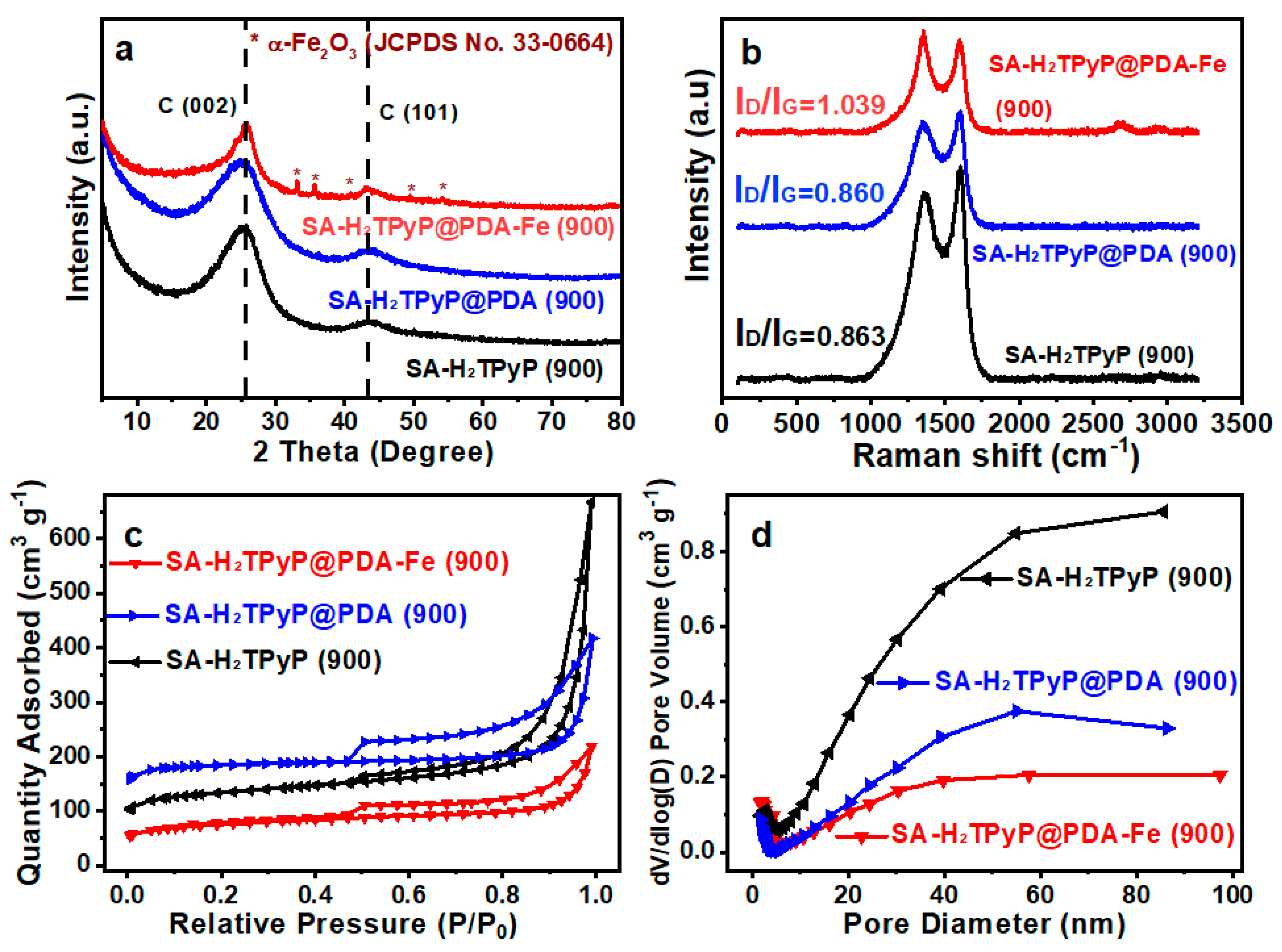
Scheme 1. Schematic illustration of preparation strategy for the SA–H2TPyP@PDA–Fe (900) electrocatalyst.
Catalysts 15 00384 sch001
Figure 1. (ac) SEM images of SA–H2TPyP, SA–H2TPyP@PDA, and SA–H2TPyP@PDA–Fe (900) electrocatalysts; (d) HAADF–STEM images of SA–H2TPyP@PDA–Fe (900) and (e) element mapping of SA–H2TPyP@PDA–Fe (900) with C, O, N, and Fe.
Catalysts 15 00384 g001
Figure 2. (a) X−ray diffraction patterns of electrocatalysts with Fe2O3 and C; (b) Raman spectra; (c) N2 adsorption−desorption isotherms; and (d) corresponding pore size distributions of SA–H2TPyP (900), SA–H2TPyP@PDA (900), and SA–H2TPyP@PDA–Fe (900) electrocatalysts.
Catalysts 15 00384 g002
Figure 3. The XPS analyses of SA–H2TPyP@PDA–Fe (900): (a) N 1s with the deconvoluted N dopants (b); (c) Fe 2p; (d) C 1s and (e) O 1s; and (f) 57Fe Mössbauer spectroscopy of SA–H2TPyP@PDA–Fe (900).
Catalysts 15 00384 g003
Figure 4. (a) LSV curves of SA–H2TPyP (900), SA–H2TPyP@PDA (900), and SA–H2TPyP@PDA–Fe (900) electrocatalysts and commercial Pt/C at 1600 rpm in an O2–saturated 0.1 M KOH solution; (b) different rotation rates from 400 to 2500 rpm of SA–H2TPyP@PDA–Fe (900) at 5 mV s−1 in a 0.1 M KOH solution; (c) K−L plots of SA–H2TPyP@PDA–Fe (900) based on data from (b); (d) the electron transfer number and HO2% of SA–H2TPyP@PDA–Fe (900) and Pt/C at 1600 rpm; (e) kinetic current densities of SA–H2TPyP@PDA–Fe (900) and Pt/C at 0.80 and 0.85 V (vs. RHE); (f) Tafel plots and (g) Cdl of SA–H2TPyP@PDA–Fe (900) and Pt/C; and (h) LSV curves of SA–H2TPyP@PDA–Fe (900) before and after 2000 CVs in O2–saturated 0.1 M KOH media.
Catalysts 15 00384 g004
Table 1. N2 adsorption−desorption parameters of SA–H2TPyP (900), SA–H2TPyP@PDA (900), and SA–H2TPyP@PDA–Fe (900) electrocatalysts.
SampleSBET
(m2 g−1)
Smic
(m2 g−1)
Vt
(cm3 g−1)
Dave (nm)
SA–H2TPyP@PDA–Fe (900)2411100.345.60
SA–H2TPyP@PDA (900)5424600.654.76
SA–H2TPyP (900)4082361.0310.11
Table 2. Mössbauer parameters determined for the different iron sites in SA–H2TPyP@PDA–Fe (900) and the assignment to iron species.
Siteδiso
(mm s−1) a
ΔEQ
(mm s−1) b
AssignmentRelative Absorption AreaRef.
Sing−0.22-Superparamagnetic Fe8.18%[36,37]
D10.213.91Low–spin, FeII–N47.53%
D20.372.67Intermediate–spin
porph–type FeII–N4
19.09%
D30.441.07Intermediate–spin Pc–type FeII–N447.32%
Sext0.39−0.18α–Fe2O317.87%
a Isomer shift. b Quadrupole splitting.
Disclaimer/Publisher’s Note: The statements, opinions and data contained in all publications are solely those of the individual author(s) and contributor(s) and not of MDPI and/or the editor(s). MDPI and/or the editor(s) disclaim responsibility for any injury to people or property resulting from any ideas, methods, instructions or products referred to in the content.

