Abstract
Alongside efficiency, long-term stability of dye-sensitized solar cells (DSSCs) is a key factor regarding their commercialization. One suitable and cost-effective method to increase the long-term stability is to prevent leakage and evaporation of the electrolyte by gelling it with polymers such as poly(ethylene oxide) (PEO) and gaining a gel polymer electrolyte (GPE). In this study, a GPE based on PEO and glycerol is investigated for the first time as electrolyte for environmentally friendly DSSCs with natural dyes. To evaluate the novel glycerol/PEO GPE, the ionic conductivity and resulting efficiency progressions of DSSCs were measured for 75 days. Different molecular weights (MWs) of PEO and blending with poly(vinylidene fluoride) (PVDF) had negligible impact on efficiencies. 17 wt% PEO was found to be more suitable than lower concentrations and resulted in a relatively high efficiency over 75 days. A glycerol electrolyte without PEO had higher ionic conductivity and achieved higher efficiencies as well but leaked from the unsealed DSSCs. In addition, the reproducibility was examined especially, which appeared to be reduced by considerable differences between identical DSSCs and between measurements of the same DSSC at different times. This emphasizes the relevance of studying multiple DSSC per sample to ensure reliable results.
1. Introduction
In the context of a globally shifting electricity generation toward low-carbon, more diversified and distributed energy systems, photovoltaic is a key technology [1]. Research in this area has explored many different directions [2]. More environmentally friendly and cost-effective alternatives to conventional silicon or thin-film technology are dye-sensitized solar cells (DSSCs) [2,3,4,5,6,7]. In the decades following their discovery in 1991, numerous scientists engaged in the optimization of this technology [2,6,7,8]. As part of this improvement, particular attention was dedicated to the power conversion efficiency [6]. Beyond this important parameter, the costs and long-term stability of DSSCs are also crucial in view of lowering the levelized cost of energy [6].
High efficiencies can be achieved with ruthenium-based dyes, such as N3 or N719, but these are hazardous to the environment due to their toxicity and are also disadvantageous in terms of their high costs [6,9]. Alternatively, non-toxic and cost-effective natural dyes can be used with the disadvantage of significantly lower efficiencies, often below 0.1% [6,9,10,11,12,13]. The long-term stability is particularly hindered by leakage and evaporation of the liquid electrolyte and thus can be improved by gelling the electrolyte or by replacing it with a solid hole-transporting material [6,14]. With the latter alternative the cost-effectiveness is expected to be limited because of the high costs of conventional hole-transporting materials [14]. A more cost-efficient alternative to ensure long-term stability is the use of polymer-based electrolytes [15]. In comparison to the liquid electrolyte, which results typically in efficiencies around 10%, all alternative electrolyte systems are associated with lower efficiencies [14,16].
As depicted in Figure 1, DSSCs are designed with four functional layers (labeled as 1) to 4) in Figure 1) between two electrodes (labeled as 0)), which are commonly composed of transparent glass substrates coated with a conductive layer, e.g. fluorine-doped tin oxide [6,14]. On the front electrode a mesoporous oxide layer, commonly TiO2, is additionally coated as first functional layer 1) [6]. Secondly, a dye sensitizer monolayer 2) is covalently bond to the surface of this semiconductor layer [6]. The third layer is composed of the electrolyte 3), which predominantly uses iodine/triiodide as redox couple [6,14]. A catalyzer layer which typically consists of Pt is coated on the counter electrode as the fourth layer 4) [6,14]. Alternatively, graphite can also be used as a cheaper material for the catalyst [17]. The energy is converted by absorbing photons from the incident light in the dye layer 2), where electrons are excited and injected into the conduction band of the semiconductor 1) [6,14]. After leaving the DSSC via the front electrode 0) work is done at the external load by the electrons, which enter the DSSC again via the counter electrode 0) [6,14]. The electrons are transported by the electrolyte 3) via redox reactions from the catalyst layer 4) to the oxidized dye 2) to regenerate it [6,14,17].
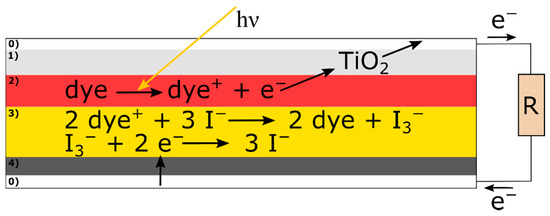
Figure 1.
Schematic structure and working principle of a DSSC. The layers labeled 0) represent the conductive glass electrodes. 1) is the TiO2 layer as first functional layer, 2) depicts the second functional layer, the dye, with the respective reaction, 3) is the electrolyte with the associated reactions of electron transport and 4) is the catalyzer as fourth functional layer.
The properties of the four functional layers, which depend often on manual coating steps, greatly influence the performance of DSSCs [9,18]. For example, the layer thickness of the catalyzer differs considerably for the same coating method and accordingly leads to large deviations in the efficiencies [17]. In addition to the complex construction of DSSCs, the pressure applied to compress the glass electrodes of a DSSC, which determines the amount of electrolyte between them, is a major cause of low reproducibility [9,18]. Unfortunately, poor reproducibility, which hinders practical application and commercialization, is only rarely addressed in the literature [18,19]. Science generally faces a problem called the reproducibility crisis [19,20,21]. In short, the pressure to publish and the bias to publish only positive outcomes lead to a lot of unreproducible experiments [19,20].
Polymer-based electrolytes exhibit an encapsulating framework, which prevents leakage and limits evaporation [14,22,23,24]. Besides other possible polymers, poly(ethylene oxide) (PEO), which is a low cost, non-toxic and semi-crystalline thermoplastic, is commonly used [14,16,25,26,27,28]. PEO can solvate electrolytic salts with a resulting coexistence of crystalline and amorphous phase, in which most ionic conduction occurs [16,27]. With these properties of PEO a solid polymer electrolyte can be applied without a solvent and with resulting efficiencies around 2%, as reported by Kalaignan et al. [29]. In this context, a limiting parameter is the relatively high crystallinity of PEO, which results in a low ionic conductivity of the electrolyte [15,29].
To reduce the crystallinity of PEO and thus enhance the ionic conductivity as well as the efficiency, several possibilities exist [23,30]. Accordingly, ionic liquids, inorganic nanofillers or plasticizers can be added to the polymer electrolyte [23]. A cost-effective and simple alternative, which also enhances the ionic conductivity and the DSSC’s efficiency, is the presence of solvent in the polymer-based electrolyte [14,15,31,32,33]. This configuration of a polymer-based electrolyte with a high content of solvent is defined in this paper as a gel polymer electrolyte (GPE). Although there is an absence of uniform definitions, this definition is often used in the literature [22,23,32]. Additionally, blending of PEO with other polymers such as poly(vinylidene fluoride) (PVDF) is a common approach to further reduce crystallinity and improve ionic conductivity [27,28,30,34,35].
Recently, Gossen et al. [4] applied glycerol as novel solvent for a liquid electrolyte for DSSCs and reached a long-term stability over 140 days. Glycerol, which is a non-toxic byproduct of biodiesel production [36], was also used by Mustafa et al. [37] as plasticizer in a PEO-based solid polymer electrolyte with a resulting enhancement of the ionic conductivity. Additionally, Kobayashi et al. [38] added glycerol as plasticizer to a solid polymer electrolyte based on poly(ethylene carbonate) and demonstrated by broadband electric spectroscopy an increase in its conductivity. Consequently, glycerol is considered a suitable solvent for a PEO-based GPE.
Here, to the best of our knowledge, a novel glycerol/PEO GPE without further additives is reported for the first time as an electrolyte system for non-toxic and environmentally friendly DSSCs with natural dyes. Different concentrations and molecular weights (MWs) of PEO as well as blending with PVDF were investigated regarding the ionic conductivities of the electrolytes and efficiencies of resulting DSSCs. Furthermore, a commercial liquid electrolyte and the glycerol electrolyte developed by Gossen et al. [4] were used as references. The evaluation of the novel glycerol/PEO GPE focuses on long-term stability and general reproducibility of DSSCs.
2. Materials and Methods
All electrodes of the investigated DSSCs were based on commercial fluorine-doped tin oxide coated glass slides manufactured by Man Solar (Petten, The Netherlands). Front electrodes were purchased with an additional TiO2 coating as semiconductor layer. The commercial liquid iodine-triiodide electrolyte used for samples 9 to 11 was also acquired from Man Solar.
As natural and non-toxic dye forest fruit tea (Mayfair, Wilken Tee GmbH, Fulda, Germany), which contains anthocyanins [39], was used for the DSSCs of samples 1 to 10. This dye proved to be promising in a previous publication [39] and was therefore used here for dyeing under a generally similar procedure. However, ethanol (Richter GmbH, Nerdlen, Germany) and distilled water in a ratio of 1:3 was applied as solvent for extraction, because this blend resulted in the highest efficiency according to Bohnenkamp et al. [40]. Specifically, 4.2 g tea was added to 50 g of the ethanol-water solution to extract the dye for 15 min under stirring at room temperature. After filtration, the permeate was used to dye the TiO2 layer of five front electrodes for 15 min at room temperature. Subsequently, excess dye was rinsed off with ethanol and the front electrodes were dried at ambient conditions before assembly. Regarding samples 10 and 11 the dyes were extracted from the forest fruit tea with distilled water for 30 min and front electrodes were subsequently dyed for 30 min. With respect to sample 11, maqui berry powder (Vitality Nutritionals, The Netherlands) was used as natural dye instead of forest fruit tea as a reference.
A graphite layer was deposited on the fluorine-doped tin oxide coated counter electrodes to obtain a catalyzer layer. Therefore, the electrodes were sprayed with graphite spray (CP-Graphitprodukte GmbH, Wachtberg, Germany) from a distance of 50 cm for 1 s. Afterwards the coated counter electrodes were treated in a heating cabinet (muffle oven B150, Nabertherm, Lilienthal, Germany) at 200 °C for 30 min. With this procedure, a graphite layer thickness of 2-4 µm is assumed according to Juhás Junger et al. [17].
Glycerol (Carl Roth, Karlsruhe, Germany) was used as solvent in the novel GPE for the polymer and the iodine-triiodide redox couple, which consisted of 15 wt% molecular iodine (I2) (Carl Roth, Karlsruhe, Germany) and 30 wt% potassium iodide (KI) (VWR, Darmstadt, Germany). PEO with the following MWs were investigated: 40 kg/mol from SERVA Electrophoresis (Heidelberg, Germany) and 100 kg/mol, 300 kg/mol, 600 kg/mol as well as 1000 kg/mol from S3 Chemicals (Bad Oeynhausen, Germany). GPEs were prepared by adding the components to glycerol and stirring for 2 h at 60 °C. The prepared GPEs were coated on the dyed front electrodes by a box-type doctor blade with a wet layer thickness of 30 µm directly before assembly. GPEs were coated at an elevated temperature on the front electrodes to achieve better penetration into the nanostructured TiO2 layer, as proposed by literature [31,35].
The properly prepared electrodes of a DSSC were placed together with the electrolyte layer in between and fixed with transparent adhesive tape. Five DSSCs were investigated per sample, except for samples 10 and 11 where only three DSSCs were built each. The individual DSSCs per sample are marked with the letters “a” to “e”. Every DSSC had an active energy conversion area of 6 cm2. Table 1 gives an overview of the investigated samples.

Table 1.
Overview of the investigated samples 1 to 11 with relevant information regarding their compositions.
Preliminary experiments indicated 17 wt% PEO as a suitable concentration. Consequently, this concentration was applied for the novel GPE in sample 1. Sample 2 was prepared with 8 wt% PEO, which corresponds to suitable PEO concentrations found in the literature [24,35]. Regarding sample 3 a polymer blend of PEO and PVDF (amboflon® from Ambofluor GmbH Co. KG, Hamburg, Germany) was investigated. The concentrations were chosen to gain a PEO/PVDF weight ratio of 8/2, which proved to be suitable [35]. The respective total polymer concentration was selected to be 8 wt% and thus slightly below the 9 wt% used in [35]. With samples 4 to 7 different MWs of PEO were investigated in the novel GPE with a constant weight ratio.
Sample 8 was constructed without polymer and in the same way as the promising DSSC developed by Gossen et al. [4] which contained a glycerol electrolyte with 15 wt% I2 and 30 wt% KI (labeled as “15%”). The electrolyte was also filled in via capillary force after the electrodes were attached together. This method of adding the electrolyte was not possible with the more viscous PEO-based GPEs. Sample 9 was constructed as a reference with a commercial liquid electrolyte (Man Solar). In this regard the liquid electrolyte was coated with a box-type doctor blade on the front electrode as it was done with the GPE.
With samples 10 and 11 the influence of the natural dye on the efficiency was investigated. In sample 10 the forest fruit tea was used as dye and the commercial liquid electrolyte (Man Solar) was filled in via capillary force, in contrast to sample 9. Dyeing of sample 11 was performed with maqui berry dye, otherwise the DSSCs were constructed analogously to sample 10. Regarding samples 10 and 11 the dye extraction procedure differed from the other samples to enable comparability with the DSSCs of Bohnenkamp et al. [40].
Measurements of the ionic conductivity were performed with a conductivity test pen (LWT-01 Voltcraft, Conrad Electronic AG, Wollerau, Switzerland) at 40 °C. Fourier-transform infrared (FTIR) spectra were recorded with an Excalibur 3100 spectroscope (Varian Inc., Palo Alto, CA, USA). A spectrum is calculated as the average of 32 scans, each acquired in attenuated total reflection mode in a wavelength range of 4000–800 cm−1, with correction for atmospheric noise. Efficiencies of the investigated DSSCs were calculated from current-voltage (I-V) curves, which were measured by a Keithley 2450 sourcemeter (Tektronix Inc., Beaverton, USA) under a standard illumination of 100 mW/cm2 from a solar simulator (LS0500, LOT-Quantum Design GmbH, Darmstadt, Germany) with an AM 1.5 G spectrum. Measurements were taken against a black background to avoid reflection and re-entering of reflected light into the DSSCs.
3. Results and Discussion
The concentration of the electrolytic salts is kept constant because their influence has already been investigated in detail by Gossen et al. [4] in connection with glycerol as solvent. Therefore, this paper focuses on the impact of the PEO in the electrolyte system. The measured ionic conductivities of the investigated electrolytes are depicted in Table 2.
Table 2.
Ionic conductivities of the glycerol/PEO GPE solutions (samples 1 to 8) and of the commercial liquid Man Solar electrolyte (sample 9). Samples were measured at 40 °C.
When comparing samples 1 and 2, it was subjectively determined that a concentration of 8 wt% PEO resulted in a more suitable viscosity regarding coating with the box-type doctor blade than 17 wt%. As it is shown in Table 2, the GPE of sample 1 had a lower ionic conductivity than the GPE of sample 2. Shi et al. [24] observed similarly with a comparable electrolyte system that a higher PEO concentration (15 wt%) results in a significantly lower conductivity compared to an optimal concentration of 8 wt% PEO. It is important to note that the here investigated ionic conductivities were approximately seven times lower than those reported by Shi et al. [24]. This is probably due to the different solvent, the different MW of PEO (namely 2000 kg/mol) and the ionic liquids added by Shi et al. [24].
By comparing the conductivities of sample 2 and 3, depicted in Table 2, it becomes apparent that the conductivity was improved by the addition of PVDF. This could be because PVDF brings disorder to the polymer matrix and thereby reduces the crystallinity of PEO, which is known to improve the conductivity of the electrolyte system [3,23,28,29,34]. In addition, it is considered that PVDF improves ionic transport and thus has a positive effect on the recombination rate caused by the presence of fluorine, which has the largest electronegativity and the smallest ionic radius [34,41]. Compared to the here presented results, Liu et al. [35] reached also a slight conductivity improvement by blending PEO with PVDF in the same ratio. Their GPE had a slightly higher ionic conductivity of 1.37 mS/cm, which is within a comparable range to sample 3, although different materials were used for the solvent and electrolytic salts [35].
The ionic conductivities of the GPEs of sample 2 and 4 to 7, which all contained PEO with different MWs, are also depicted in Table 2. No trend can be observed in these conductivity values regarding the influence of MW on ionic conductivity. The measured conductivities of samples 2 (600 kg/mol), 4 (40 kg/mol) and 5 (100 kg/mol) were almost identical. Sample 7 (1000 kg/mol) had a slightly higher value and the GPE of sample 6 (300 kg/mol) resulted in the relatively highest ionic conductivity of the investigated MWs. The MWs used here, 40–1000 kg/mol, were all in a range where the MW does not influence the conductivity of PEO with added salts [42]. A pronounced influence of the MW of PEO on the conductivity can only be observed below 10 kg/mol [42,43]. Thus, the differences observed here regarding the conductivities of samples 2 and 4 to 7 were most probably due to deviations in the measurement or solution preparation.
As can be seen in Table 2, the ionic conductivity of sample 8 was significantly higher than the ionic conductivities of the other samples. This difference is probably due to the added PEO in the electrolytes of samples 1 to 7. Apparently, the ionic conductivity is further reduced with a higher PEO concentration (compare samples 1 and 2 in Table 2). Those observations correspond to literature, because it is stated that with a higher PEO concentration the polymer matrix is more pronounced and the free volume, in which most ionic conduction occurs, as well as the diffusion coefficient of the redox couple is reduced [16,22,24,29].
Interestingly, the ionic conductivity of the commercial liquid Man Solar electrolyte (sample 9 in Table 2) was measured significantly lower than the ionic conductivities of the other samples. Since the exact composition of this commercial electrolyte is not known, another, presumably lower, concentration of electrolytic salts, which strongly influence the electrolyte system [29], is assumed to be the cause of the significantly lower ionic conductivity.
Kalaignan et al. [29] used PEO with 1000 kg/mol as basis for a solid polymer electrolyte applied in DSSCs and measured conductivities at 44 °C in a range of 0.02–0.08 mS/cm depending on the KI/I2 ratio. Compared to this, a significantly higher conductivity was reached here, e.g., with sample 7 applying the same MW (cf. Table 2). This is probably due to the absence of a solvent in the solid polymer electrolyte of Kalaignan et al. [29], since it is known that solvent remaining in the GPE increases its conductivity [15,29,31,33].
The novel glycerol/PEO GPE, like most GPE systems, aims to ensure high long-term stability of DSSCs by preventing leakage and evaporation of the electrolyte [14,15,32,44]. Therefore, in the following the different samples are compared with regard to the temporal efficiency developments of the respective DSSCs.
It was observed that some DSSCs of a sample always had very low efficiencies compared to the other specimen of the same sample, hence a presentation of the results as mean value with standard deviation is considered unsuitable. To ensure a clear overview while presenting all results, the two best DSSCs per sample are shown in one part of a figure (e.g., Figure 2a) and the remaining ones in the second part (e.g., Figure 2b). A DSSC is defined here as “better” than the others per sample if the efficiency is long-term stable and higher than the others at the end of the measurement period. Firstly, the efficiency progressions of samples 1 to 3 are shown in Figure 2.
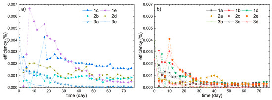
Figure 2.
Comparison of the efficiency progressions of samples 1, 2 and 3. The two more efficient DSSCs per sample are depicted in (a) and the remaining DSSCs in (b). In the electrolyte of sample 1, 17 wt% PEO was applied and 8 wt% PEO in sample 2. Sample 3 contained 6.4 wt% PEO and 1.6 wt% PVDF.
By comparing the relatively best DSSCs of samples 1 and 2, which are depicted in Figure 2a, it becomes apparent that the different PEO concentrations influenced the efficiency progressions only slightly. The higher PEO concentration of sample 1 seems to result in a slightly higher efficiency and exhibits a different course with respect to 1e with a peak around day 7. This peak could be attributed to the time needed for a viscous GPE for the critical complete penetration into the nanoporous TiO2 layer, which often causes an efficiency peak in the early days of a DSSC [13,15,17,29,30,31,44]. Such efficiency peaks are also visible regarding sample 1c on day 17 and 1b as well as 2e on day 10 (cf. Figure 2b).
The best DSSCs of sample 3 had lower efficiency values and exhibited sharper efficiency decreases with efficiencies close to zero after 45 days. Resultingly, the long-term stability of sample 3 is considered poorer in comparison to samples 1 and 2. Originally, it was hypothesized that the relatively high ionic conductivity of the GPE of sample 3 (cf. Table 2) results in an also high efficiency of the DSSCs. However, considering the results in Figure 2, this hypothesis could not be confirmed. With the poor efficiency of sample 3 it is assumed that other factors besides the ionic conductivity, like the dye or deviations in the preparation, are limiting and responsible for the poor efficiencies.
Compared to Liu et al. [35], who applied a similar PEO/PVDF blend as electrolyte with a generally similar ionic conductivity, the highest efficiency of sample 3 (on the first day) was lower by a factor of about 2000. This is primarily due to the here used environmentally friendly natural dye instead of the toxic ruthenium dye applied by Liu et al. [35], because natural dyes generally result in low efficiencies [9,10,11,12,13]. Additionally, the relatively large active areas of the investigated DSSCs result in lower efficiencies than smaller DSSCs [7,18].
Regarding the poorer DSSCs of samples 1 to 3 depicted in Figure 2b, the DSSCs of sample 3 seem to exhibit slightly lower efficiencies compared to samples 1 and 2. The resulting efficiencies of the PEO/PVDF blend of sample 3 were almost zero after approximately 55 days. To identify potential reasons for this lower long-term stability, further tests will be carried out in the future. Generally, a decreasing trend of the DSSCs depicted in Figure 2b is visible within the first 40 days followed by low but relatively constant efficiencies.
Considering the large differences in efficiency between five DSSCs per sample at a measuring point (cf. sample 1 in Figure 2), a low reproducibility can be assumed. In this context, it has an extremely large influence on the evaluation of the performance of a certain electrolyte system, whether just the best measured efficiency per sample is presented or all of the data. If only one efficiency was shown (e.g., sample 1c), the reliability and performance of that sample would be overestimated. Consequently, to avoid such premature conclusions, all five DSSCs per sample are considered here. Following this approach, the actual performance, which can be reproducibly achieved and which is crucial for practical application, becomes questionable and less evident. Thus, regarding samples 1 to 3, it is not distinct whether the differences in the efficiency curves in Figure 2a resulted from different GPEs or were random.
Next, in Figure 3 the long-term efficiency progressions of samples 4 to 7 are presented. Those samples applied PEO with different MWs in the novel glycerol/PEO GPE. As depicted in Figure 3a, the DSSC efficiencies of samples 4 to 7 progressed all very similarly. Until day 25 the efficiencies decreased relatively constantly by a factor four and remained at low values thereafter. In contrast to Figure 3a, most DSSCs depicted in 3b were with an efficiency of almost zero after 30 days no longer functional. The efficiency of sample 2 with PEO with 600 kg/mol (depicted in Figure 2) had a nearly identical progression. No influence of the MWs of PEO on the temporal development of the efficiencies is detectable based on this data.
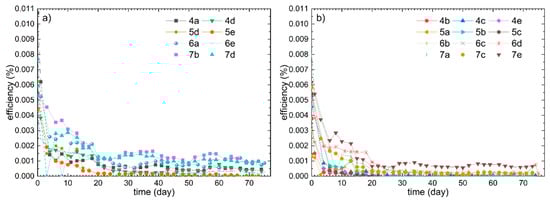
Figure 3.
Efficiency curves of the two best DSSCs of samples 4 to 7, all with different MWs of PEO, are shown in (a) and the progressions of the further DSSCs of those samples are shown in (b). The following MWs were applied: 40 kg/mol in sample 4, 100 kg/mol in 5, 300 kg/mol in 6 and 1000 kg/mol in 7.
According to literature, the MW of PEO is an important parameter in relation to the contact of the GPE with the nanoporous TiO2 layer [30]. This is due to the coil size of PEO, which is determined by the polymer’s radius of gyration that varies with the MW and chain length [30,45,46,47,48,49]. With a high MW and a coil size larger than the pores of the TiO2 layer, adequate penetration into a TiO2 pore is hindered and a poor contact to the TiO2 layer as well as a low efficiency are the results [30,45,46,47,48,49]. As the coil sizes were not investigated, too large coil sizes of the applied MWs of PEO, with resulting poor contact to the TiO2 layer, cannot be excluded as a cause for the low efficiencies.
The samples 8 and 9 functioned as references applying liquid electrolyte systems without any polymer. Sample 8 had a glycerol electrolyte developed by Gossen et al. [4] and for sample 9 a commercial liquid electrolyte was applied. The efficiency progressions of the respective DSSCs are depicted in Figure 4.
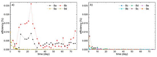
Figure 4.
The efficiency progressions of the best DSSCs of samples 8 and 9 are depicted in (a) and the other DSSCs of those samples in (b). The DSSCs of sample 8 were constructed in the same way as the sample marked as “15%” by Gossen et al. [4], except for slight differences in the recipe for preparing the dye. In sample 9 the commercial liquid Man Solar electrolyte was coated on the front electrode in the same way as it was done with the GPE.
In Figure 4 it is recognizable that the efficiencies of all DSSCs of sample 9 were relatively low and no longer functional after approximately 10 days. In contrast to this, the efficiency progressions of 8a and 8b had significantly higher values than all other here investigated DSSCs. However, the measured efficiencies of samples 8a and 8b exhibited very pronounced fluctuations over time.
These fluctuations result presumably from measurement deviations due to a lack of electric contact between connection clamps and fluorine-doped tin oxide layers. The disturbance of the electrical contact may be caused by the attachment of the clamps on the glass electrodes, which always results in slight damage to the conductive fluorine-doped tin oxide coatings. If the clamps are then again placed in already scratched areas during the next measurement, the resistance is probably higher and the efficiency is measured lower. Consequently, the measuring process causes additional deviations and the reproducibility is restricted. Thus, the low efficiency values under 0.005% of sample 8b are presumably due to these deviations. Probably, fluctuations in the efficiency curves of other samples are also based on this (cf. sample 1d on day 3 and 7, samples 2a, 2b and 2d, sample 6a on day 8 and sample 7d on day 3).
The fact that samples 8a and 8b had relatively high efficiencies while the other DSSCs of sample 8 had an efficiency close to zero after 30 days shows the large discrepancies within identical DSSCs and indicates a major problem with reproducibility. This reproducibility problem becomes even clearer by comparing the efficiency progressions of sample 8 with the respective progression of the DSSC labeled as “15%” measured by Gossen et al. [4]. The efficiency of the latter was over 0.02% for 140 days and had a peak efficiency at day 60 of about 0.07% [4]. A probable cause for the large discrepancy between sample 8 and the DSSC of Gossen et al. [4] is a change in the composition of the forest fruit tea. This would also explain the low efficiencies of the other here investigated DSSCs compared to earlier publications of our working group [4,17,39,40].
To investigate this, sample 10 was constructed with the currently available forest fruit tea from Mayfair mostly similarly to the DSSCs investigated by Bohnenkamp et al. [40], which were built with old forest fruit tea from Mayfair in 2018. Additionally, maqui berry powder was used to dye the TiO2 layers of sample 11, like it was also done by Bohnenkamp et al. [40]. The resulting efficiency progressions of sample 10 and 11 are shown in Figure 5.
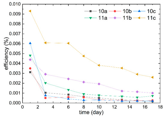
Figure 5.
Temporal efficiency progressions of the DSSCs of samples 10 and 11. With sample 10 the Man Solar electrolyte was filled in via capillary force and in sample 11 maqui berry dye was used.
Bohnenkamp et al. [40] achieved with the old forest fruit tea dye a higher efficiency than with the maqui berry dye. The efficiencies resulting from the maqui berry dye were in a similar range as the efficiencies of sample 11 depicted in Figure 5 [40]. In contrast to the results of Bohnenkamp et al. [40], the new forest fruit tea dye, applied in sample 10, resulted in lower efficiencies than the maqui berry dye, applied in sample 11. Consequently, it can be assumed that there are certain alterations in the forest fruit tea, so that the current one results in lower efficiencies overall. This is probably a reason for the low efficiency levels achieved here compared to old publications with similar DSSCs [4,17,39,40].
Another reason for low efficiencies compared to previous publications could be the use of a rough black textile as background for the measurement, which was not used before. This prevents radiated light reflected behind the DSSC from exciting the dye by re-entering through the counter electrode. Therefore, less of the applied light can effectively be harvested, which reduces the total area efficiency of a DSSC [7,50]. With a reflective background the efficiency can be increased by about 6% compared to a black background [7]. Unfortunately, the background on which DSSCs are measured is usually not specified, which makes it difficult to reproduce and compare the results.
In addition to the deviations in the purchased materials and the exact conditions during the measurements, the contact pressure of the two glass electrodes was identified as a cause for low reproducibility [18]. Furthermore, assembling DSSCs under laboratory conditions requires a lot of manual work, which greatly reduces the comparability and reproducibility of DSSCs.
By comparing sample 9 with sample 10 (cf. Figure 4 and Figure 5), it becomes apparent that the coating on the front electrode with the liquid electrolyte may be less suitable than the method of loading via capillary force, because of the more rapid efficiency decrease of sample 9 after day 1. Despite the lower ionic conductivity of the commercial liquid electrolyte, the corresponding DSSCs (samples 9 to 11) had relatively high efficiencies at the beginning (e.g., sample 9c). However, the samples with commercial liquid electrolytes exhibited a poor long-term stability resulting from a sharp efficiency decrease in the first weeks. This is probably due to leakage and evaporation of the electrolyte as this is the common reason for degradation of unsealed DSSCs with liquid electrolytes [3,4,9,14]. In contrast to this, a significantly better long-term stability of the efficiency was reached by the novel glycerol/PEO GPE (cf. Figure 2 and Figure 3). This is explained by the polymer matrix, which hinders leakage and evaporation by trapping the solvent and electrolytic salts [14,22,23,24].
The glycerol electrolyte developed by Gossen et al. [4], without added polymer, can also result in relatively long-term stable DSSCs (cf. Figure 4a). Based on this it is expected that the low vapor pressure and low viscosity of glycerol prevents leakage and evaporation [51,52]. The hygroscopic properties of glycerol may also have a positive effect on long-term stability [53]. Compared to the electrolytes with added PEO, higher efficiencies were gained with the pure glycerol electrolyte. This is most probably due to the higher conductivity (cf. Table 2) and the unrestricted contact with the TiO2 layer. A poor contact between the GPE and the dyed TiO2 layer is, besides a high crystallinity, commonly considered to be a reason for reduced efficiencies [14,15,23,29,30]. Generally, it is known that the addition of polymers reduces the efficiency due to increased viscosity and limited ionic conductivity [16,22,24,29].
However, by gelling with PEO it was observed that the electrolyte is less likely to leak from the unsealed DSSCs, which was observed regarding samples 8 to 11, thus the robustness is increased by PEO. However, an improved long-term stability due to the addition of PEO could not be determined based on the measurements compared to the pure glycerol electrolyte. Therefore, both sample 1, which resulted in relatively long-term stable efficiencies with a glycerol/PEO GPE, and sample 8, which achieved the highest efficiencies with the pure glycerol electrolyte, are considered the most suitable approaches. Thus, glycerol is not only estimated suitable as plasticizer in solid polymer electrolytes [37,38], but also as a solvent in GPEs. To further characterize the electrolyte systems of samples 1 and 8, FTIR spectra of them and of pure glycerol are depicted in Figure 6.
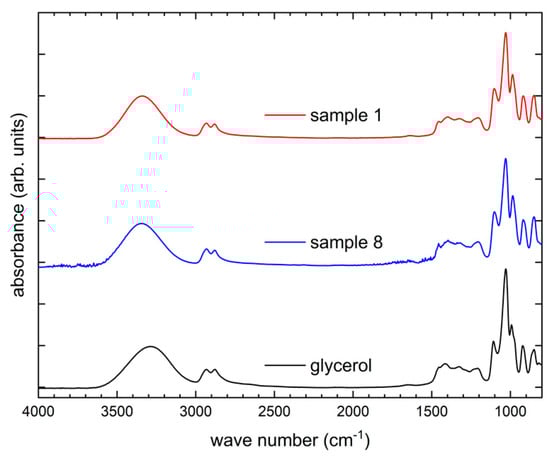
Figure 6.
FTIR spectra of pure glycerol, the GPE of sample 8 with KI and I2 solved in glycerol and the GPE of sample 1 composed of glycerol, KI, I2, and PEO. The graphs are shifted vertically for clarity.
The FTIR spectrum of pure glycerol depicted in Figure 6 is very similar to those reported in the literature [54,55,56]. The broad peak from 3500–3000 cm−1 can e.g., be attributed to the O‒H functional groups matching the molecular structure of glycerol [55]. With the addition of KI and I2 as electrolytic salts in sample 8, no other peaks than those of pure glycerol are apparent. This is because the ions of the electrolyte cannot be detected by FTIR and the I2 content does not affect the spectrum [29].
By comparing the FTIR spectrum of sample 1 containing PEO with that of pure glycerol no significant difference can be observed in Figure 6. The absorption peaks characteristic of PEO are superposed by the peaks of pure glycerol and are thus probably indistinguishable from the latter [57,58,59,60]. For example, PEO absorbs typically around 2854 cm−1 (‒CH2 stretching), around 1359 cm−1 (‒CH2 wagging) or around 1094 cm−1 (C‒O‒C stretching) [57], while glycerol absorbs also at those wave numbers (cf. Figure 6). The Absorption at similar wave numbers regarding PEO and glycerol is plausible, since chemical groups such as ‒CH2 appear in both molecules.
Furthermore, the DSSCs of samples 1 and 8, as promising approaches, are electrically characterized in more detail. In this regard, the respective I-V curves of day 3, at which typically the highest efficiencies are measured due to pore filling [13,17], are depicted in Figure 7.
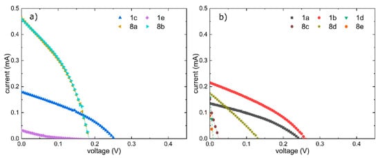
Figure 7.
I-V curves of DSSCs from sample 1 and 8 at day 3. The DSSCs considered better in terms of long-term stability are shown in (a) and the others in (b).
Apart from samples 8a and 8b, the I-V curves shown in Figure 7 illustrate the strong deviations between identical DSSCs. These deviations resulted in large standard deviations of the averaged efficiencies, which were (0.0015 ± 0.0014)% for sample 1 and (0.0023 ± 0.0027)% for sample 8. As these standard deviations, which were already large at day 3, became larger over time, it is questionable how reproducible and representative these results are. Thus, resulting from the insufficient reproducibility, a distinctive evaluation of the novel glycerol/PEO GPE is not possible with these data. The glycerol/PEO GPE tends to be less suitable than the glycerol electrolyte from Gossen et al. [4].
To make our humble contribution to respond to the reproducibility crisis [19,20,21] we publish these rather negative results, which on the one hand have very low efficiencies compared to results of other scientists and on the other hand show a lack of reproducibility of our own results. Especially because of the known low reproducibility of DSSCs [9,18] we consider it important to investigate as many DSSCs as feasible and to specify all efficiencies and their temporal progressions in contrast to the observed trend in the literature of showing only one efficiency per sample without standard deviations [3,4,13,14,16,24,29,31,34,35,39,46,47,50,61,62,63,64].
4. Conclusions
A novel glycerol/PEO GPE was presented and evaluated regarding its ionic conductivity and the resulting efficiency progressions over 75 days of DSSCs assembled with it. Different MWs of PEO had no significant influences on the conductivities or efficiency progressions. Blending of PEO with PVDF resulted in a higher ionic conductivity but also in a poor long-term stability with relatively low efficiencies. A higher concentration of PEO resulted with 17 wt% in sample 1, despite a slightly lower ionic conductivity, in overall higher long-term efficiencies compared to 8 wt% in the other samples.
The composition of sample 1, with which a stable efficiency around 0.002% after 75 days can be reached, is considered the most suitable of the novel glycerol/PEO GPE. However, compared to the glycerol electrolyte without polymer of sample 8, the novel GPE of sample 1 resulted in a significantly lower ionic conductivity and a poorer long-term stability, with lower efficiencies as well. Although a reduced electrolyte leakage was detected subjectively regarding the GPE of sample 1, the measured values were in comparison with sample 8 not affected by this.
The lower efficiencies compared to previous publications with similar DSSCs can be partly attributed to a change in the purchased dye. Generally compared to literature, quite low efficiencies were reached, predominantly because of the use of natural dyes and overall non-toxic components.
Altogether, the results presented here show a major problem with insufficient reproducibility concerning DSSCs. Specifically, the problem was manifested in large deviations between the efficiencies of identical DSSCs, which make a final evaluation of the novel glycerol/PEO GPE based on the presented data impossible. In this regard, further research will be conducted in the near future. Generally, the scientific community should address the overall problem of low reproducibility by obtaining statistical certainty by considering multiple replicas per sample.
Author Contributions
Conceptualization, J.L.S. and M.D.; Investigation, J.L.S., M.D. and B.B.; Methodology, J.L.S. and M.D.; Project administration, M.D.; Validation, all authors; Visualization, M.D. and T.G.; Writing—original draft preparation, J.L.S.; Writing—review and editing, all authors. All authors have read and agreed to the published version of the manuscript.
Funding
This research was funded by Deutsche Bundesstiftung Umwelt DBU (German Federal Environmental Foundation). The APC is funded by the Open Access Publication Fund of Bielefeld University of Applied Sciences.
Conflicts of Interest
The authors declare no conflict of interest. The funders had no role in the design of the study; in the collection, analyses, or interpretation of data; in the writing of the manuscript, or in the decision to publish the results.
References
- McLellan, B.; Florin, N.; Giurco, D.; Kishita, Y.; Itaoka, K.; Tezuka, T. Decentralised energy futures: The changing emissions reduction landscape. Procedia CIRP 2015, 29, 138–143. [Google Scholar] [CrossRef]
- Asghar, M.I.; Miettunen, K.; Halme, J.; Vahermaa, P.; Toivola, M.; Aitola, K.; Lund, P. Review of stability for advanced dye solar cells. Energy Environ. Sci. 2010, 3, 418. [Google Scholar] [CrossRef]
- Syairah, A.; Khanmirzaei, M.H.; Saidi, N.M.; Farhana, N.K.; Ramesh, S.; Ramesh, K. Effect of different imidazolium-based ionic liquids on gel polymer electrolytes for dye-sensitized solar cells. Ionics 2019, 25, 2427–2435. [Google Scholar] [CrossRef]
- Gossen, K.; Ehrmann, A. Glycerin-based electrolyte for reduced drying of dye-sensitized solar cells. Optik 2020, 207, 163772. [Google Scholar] [CrossRef]
- Mamun, A.; Trabelsi, M.; Klöcker, M.; Sabantina, L.; Großerhode, C.; Blachowicz, T.; Grötsch, G.; Cornelißen, C.; Streitenberger, A.; Ehrmann, A. Electrospun nanofiber mats with embedded non-sintered TiO2 for dye-sensitized solar cells (DSSCs). Fibers 2019, 7, 60. [Google Scholar] [CrossRef]
- Gong, J.; Sumathy, K.; Qiao, Q.; Zhou, Z. Review on dye-sensitized solar cells (DSSCs): Advanced techniques and research trends. Renew. Sustain. Energy Rev. 2017, 68, 234–246. [Google Scholar] [CrossRef]
- Lee, W.J.; Ramasamy, E.; Lee, D.Y.; Song, J.S. Dye-sensitized solar cells: Scale up and current–voltage characterization. Sol. Energy Mater. Sol. Cells 2007, 91, 1676–1680. [Google Scholar] [CrossRef]
- O’Regan, B.; Grätzel, M. A low-cost, high-efficiency solar cell based on dye-sensitized colloidal TiO2 films. Nature 1991, 353, 737–740. [Google Scholar] [CrossRef]
- Ehrmann, A.; Blachowicz, T. Recent coating materials for textile-based solar cells. AIMS Mater. Sci. 2019, 6, 234–251. [Google Scholar] [CrossRef]
- Ehrmann, A.; Blachowicz, T. Comment on ‘Dye-sensitized solar cells using aloe vera and cladode of cactus extracts as natural sensitizers’ [Chem. Phys. Lett. 679 (2017) 97–101]. Chem. Phys. Lett. 2019, 714, 227–229. [Google Scholar] [CrossRef]
- Gossen, K.; Storck, J.L.; Ehrmann, A. Influence of solvents on aloe vera gel performance in dye-sensitized solar cells. Optik 2019, 180, 615–618. [Google Scholar] [CrossRef]
- Junger, I.J.; Homburg, S.V.; Grethe, T.; Herrmann, A.; Fiedler, J.; Schwarz-Pfeiffer, A.; Blachowicz, T.; Ehrmann, A. Examination of the sintering process-dependent properties of TiO2 on glass and textile substrates. J. Photon. Energy 2017, 7, 15001. [Google Scholar] [CrossRef]
- Junger, I.J.; Homburg, S.V.; Meissner, H.; Grethe, T.; Pfeiffer, A.S.; Fiedler, J.; Herrmann, A.; Blachowicz, T.; Ehrmann, A. Influence of the pH value of anthocyanins on the electrical properties of dye-sensitized solar cells. AIMS Energy 2017, 5, 258–267. [Google Scholar] [CrossRef]
- Iftikhar, H.; Sonai, G.G.; Hashmi, S.G.; Nogueira, A.F.; Lund, P.D. Progress on electrolytes development in dye-sensitized solar cells. Materials (Basel) 2019, 12, 1998. [Google Scholar] [CrossRef] [PubMed]
- Song, D.; Cho, W.; Lee, J.H.; Kang, Y.S. Toward higher energy conversion efficiency for solid polymer electrolyte dye-sensitized solar cells: Ionic conductivity and TiO2 pore-filling. J. Phys. Chem. Lett. 2014, 5, 1249–1258. [Google Scholar] [CrossRef]
- Dissanayake, M.A.K.L.; Ekanayake, E.M.B.S.; Bandara, L.R.A.K.; Seneviratne, V.A.; Thotawatthage, C.A.; Jayaratne, S.L.; Senadeera, G.K.R. Efficiency enhancement by mixed cation effect in polyethylene oxide (PEO)-based dye-sensitized solar cells. J. Solid State Electrochem. 2016, 20, 193–201. [Google Scholar] [CrossRef]
- Junger, I.J.; Großerhode, C.; Storck, J.L.; Kohn, S.; Grethe, T.; Grassmann, C.; Schwarz-Pfeiffer, A.; Grimmelsmann, N.; Meissner, H.; Blachowicz, T.; et al. Influence of graphite-coating methods on the DSSC performance. Optik 2018, 174, 40–45. [Google Scholar] [CrossRef]
- Hölscher, F.; Trümper, P.-R.; Junger, I.J.; Schwenzfeier-Hellkamp, E.; Ehrmann, A. Raising reproducibility in dye-sensitized solar cells under laboratory conditions. J. Renew. Sustain. Energy 2018, 10, 13506. [Google Scholar] [CrossRef]
- Wortmann, M.; Layland, A.S.; Frese, N.; Kahmann, U.; Grothe, T.; Storck, J.L.; Blachowicz, T.; Grzybowski, J.; Hüsgen, B.; Ehrmann, A. On the reliability of highly magnified micrographs for structural analysis in materials science. Sci. Rep. 2020, 10, 14708. [Google Scholar] [CrossRef]
- Baker, M. 1500 scientists lift the lid on reproducibility. Nature 2016, 533, 452–454. [Google Scholar] [CrossRef]
- National Academies of Sciences, Engineering, and Medicine. Reproducibility and Replicability in Science; National Academies Press: Washington, DC, USA, 2019. [Google Scholar] [CrossRef]
- Wang, Y. Recent research progress on polymer electrolytes for dye-sensitized solar cells. Sol. Energy Mater. Sol. Cells 2009, 93, 1167–1175. [Google Scholar] [CrossRef]
- de Freitas, J.N.; Nogueira, A.F.; de Paoli, M.-A. New insights into dye-sensitized solar cells with polymer electrolytes. J. Mater. Chem. 2009, 19, 5279. [Google Scholar] [CrossRef]
- Shi, Y.; Zhan, C.; Wang, L.; Ma, B.; Gao, R.; Zhu, Y.; Qiu, Y. The electrically conductive function of high-molecular weight poly(ethylene oxide) in polymer gel electrolytes used for dye-sensitized solar cells. Phys. Chem. Chem. Phys. 2009, 11, 4230–4235. [Google Scholar] [CrossRef] [PubMed]
- Huang, L.; Nagapudi, K.; Apkarian, R.P.; Chaikof, E.L. Engineered collagen-PEO nanofibers and fabrics. J. Biomater. Sci. Polym. Ed. 2001, 12, 979–993. [Google Scholar] [CrossRef] [PubMed]
- Lei, B.; Li, G.-R.; Chen, P.; Gao, X.-P. A quasi-solid-state solar rechargeable battery with polyethylene oxide gel electrolyte. ACS Appl. Energy Mater. 2019, 2, 1000–1005. [Google Scholar] [CrossRef]
- Ida, J.; Suthanthiraraj, S.A. Investigation on the effect of nitrogenous compound benzotriazole on the structural, thermal and dielectric properties of PEO-PMMA blended polymer electrolyte system and its performance in dye sensitized solar cells. Macromol. Res. 2019, 27, 346–353. [Google Scholar] [CrossRef]
- Chen, P.; Liang, X.; Wang, J.; Zhang, D.; Yang, S.; Wu, W.; Zhang, W.; Fan, X.; Zhang, D. PEO/PVDF-based gel polymer electrolyte by incorporating nano-TiO2 for electrochromic glass. J. Sol. Gel. Sci. Technol. 2017, 81, 850–858. [Google Scholar] [CrossRef]
- Kalaignan, G.; Kang, M.; Kang, Y. Effects of compositions on properties of PEO–KI–I2 salts polymer electrolytes for DSSC. Solid State Ion. 2006, 177, 1091–1097. [Google Scholar] [CrossRef]
- Singh, P.K.; Nagarale, R.K.; Pandey, S.P.; Rhee, H.W.; Bhattacharya, B. Present status of solid state photoelectrochemical solar cells and dye sensitized solar cells using PEO-based polymer electrolytes. Adv. Nat. Sci: Nanosci. Nanotechnol. 2011, 2, 23002. [Google Scholar] [CrossRef]
- Nogueira, A.F.; Durrant, J.R.; de Paoli, M.A. Dye-sensitized nanocrystalline solar cells employing a polymer electrolyte. Adv. Mater. 2001, 13, 826–830. [Google Scholar] [CrossRef]
- Anantharaj, G.; Joseph, J.; Selvaraj, M.; Jeyakumar, D. Fabrication of stable dye sensitized solar cell with gel electrolytes using poly(ethylene oxide)-poly(ethylene glycol). Electrochim. Acta 2015, 176, 1403–1409. [Google Scholar] [CrossRef]
- Awadhia, A.; Agrawal, S.L. Structural, thermal and electrical characterizations of PVA:DMSO:NH4SCN gel electrolytes. Solid State Ion. 2007, 178, 951–958. [Google Scholar] [CrossRef]
- Han, H.W.; Liu, W.; Zhang, J.; Zhao, X.-Z. A hybrid poly(ethylene oxide)/poly(vinylidene fluoride)/TiO2 nanoparticle solid-state redox electrolyte for dye-sensitized nanocrystalline solar cells. Adv. Funct. Mater. 2005, 15, 1940–1944. [Google Scholar] [CrossRef]
- Liu, I.-P.; Hung, W.-N.; Teng, H.; Venkatesan, S.; Lin, J.-C.; Lee, Y.-L. High-performance printable electrolytes for dye-sensitized solar cells. J. Mater. Chem. A 2017, 5, 9190–9197. [Google Scholar] [CrossRef]
- Qiu, Z.; Zhang, Y.; Li, Y.; Sun, J.; Wang, R.; Wu, X. Glycerol as a leveler on ZK60 magnesium alloys during plasma electrolytic oxidation. RSC Adv. 2015, 5, 63738–63744. [Google Scholar] [CrossRef]
- Mustafa, M.O.; Ghareeb, H.B.; Aziz, S.; Brza, M.A.; Al-Zangana, S.; Hadi, J.M.; Kadir, M.F.Z. Electrochemical characteristics of glycerolized PEO-based polymer electrolytes. Membranes (Basel) 2020, 10, 116. [Google Scholar] [CrossRef] [PubMed]
- Kobayashi, K.; Pagot, G.; Vezzù, K.; Bertasi, F.; Di Noto, V.; Tominaga, Y. Effect of plasticizer on the ion-conductive and dielectric behavior of poly(ethylene carbonate)-based Li electrolytes. Polym. J. 2021, 53, 149–155. [Google Scholar] [CrossRef]
- Kohn, S.; Großerhode, C.; Storck, J.L.; Grötsch, G.; Cornelißen, C.; Streitenberger, A.; Grassmann, C.; Schwarz-Pfeiffer, A.; Ehrmann, A. Commercially available teas as possible dyes for dye-sensitized solar cells. Optik 2019, 185, 178–182. [Google Scholar] [CrossRef]
- Bohnenkamp, B.; Linnemann, J.-H.; Junger, I.J.; Schwenzfeier-Hellkamp, E.; Ehrmann, A. Influence of different solvents on the electrical properties of dye-sensitized solar cells. J. Renew. Sustain. Energy 2018, 10, 63701. [Google Scholar] [CrossRef]
- He, M.J.; Chen, W.X.; Dong, X.X. Polymer Physics; Fudan University Publishers: Shanghai, China, 1990. [Google Scholar]
- Teran, A.A.; Tang, M.H.; Mullin, S.A.; Balsara, N.P. Effect of molecular weight on conductivity of polymer electrolytes. Solid State Ion. 2011, 203, 18–21. [Google Scholar] [CrossRef]
- Hayamizu, K.; Akiba, E.; Bando, T.; Aihara, Y. 1H, 7Li, and 19F nuclear magnetic resonance and ionic conductivity studies for liquid electrolytes composed of glymes and polyetheneglycol dimethyl ethers of CH3O(CH2CH2O)nCH3 (n = 3–50) doped with LiN(SO2CF3)2. J. Chem. Phys. 2002, 117, 5929–5939. [Google Scholar] [CrossRef]
- Sonai, G.G.; Tiihonen, A.; Miettunen, K.; Lund, P.D.; Nogueira, A.F. Long-term stability of dye-sensitized solar cells assembled with cobalt polymer gel electrolyte. J. Phys. Chem. C 2017, 121, 17577–17585. [Google Scholar] [CrossRef]
- Kim, Y.J.; Kim, J.H.; Kang, M.-S.; Lee, M.J.; Won, J.; Lee, J.C.; Kang, Y.S. Supramolecular electrolytes for use in highly efficient dye-sensitized solar cells. Adv. Mater. 2004, 16, 1753–1757. [Google Scholar] [CrossRef]
- Kim, J.H.; Kang, M.-S.; Kim, Y.J.; Won, J.; Park, N.-G.; Kang, Y.S. Dye-sensitized nanocrystalline solar cells based on composite polymer electrolytes containing fumed silica nanoparticles. Chem. Commun. Camb. 2004, 1662–1663. [Google Scholar] [CrossRef]
- Kang, M.-S.; Kim, J.H.; Won, J.; Kang, Y.S. Oligomer approaches for solid-state dye-sensitized solar cells employing polymer electrolytes. J. Phys. Chem. C 2007, 111, 5222–5228. [Google Scholar] [CrossRef]
- Kang, M.-S.; Kim, J.H.; Won, J.; Kang, Y.S. Dye-sensitized solar cells based on crosslinked poly(ethylene glycol) electrolytes. J. Photochem. Photobiol. A Chem. 2006, 183, 15–21. [Google Scholar] [CrossRef]
- Kang, M.-S.; Ahn, K.-S.; Lee, J.-W.; Kang, Y.S. Dye-sensitized solar cells employing non-volatile electrolytes based on oligomer solvent. J. Photochem. Photobiol. A Chem. 2008, 195, 198–204. [Google Scholar] [CrossRef]
- Chien, C.-H.; Tsai, M.-L.; Hsieh, C.-C.; Li, Y.-H.; Chao, Y.J. A light harvesting policy on black counter electrode for enhanced performance of dye-sensitized solar cells. J. Sol. Energy Eng. 2014, 136. [Google Scholar] [CrossRef]
- Segur, J.B.; Oberstar, H.E. Viscosity of Glycerol and Its Aqueous Solutions. Ind. Eng. Chem. 1951, 43, 2117–2120. [Google Scholar] [CrossRef]
- Lide, D.R.; Milne, G.W.A. Handbook of Data on Organic Compounds, 3rd ed.; CRC Press: Boca Raton, FL, USA, 1994. [Google Scholar]
- Christoph, R.; Schmidt, B.; Steinberner, U.; Dilla, W.; Karinen, R. Ullmann’s Encyclopedia of Industrial Chemistry; Wiley-VCH Verlag GmbH & Co. KGaA: Weinheim, Germany, 2000; ISBN 3527306730. [Google Scholar]
- Nanda, M.R.; Yuan, Z.; Qin, W.; Poirier, M.A.; Chunbao, X. Purification of crude glycerol using acidification: Effects of acid types and product characterization. Austin J. Chem. Eng. 2014, 1, 1–7. [Google Scholar]
- AlOmar, M.K.; Hayyan, M.; Alsaadi, M.A.; Akib, S.; Hayyan, A.; Hashim, M.A. Glycerol-based deep eutectic solvents: Physical properties. J. Mol. Liq. 2016, 215, 98–103. [Google Scholar] [CrossRef]
- Liu, H.; Adhikari, R.; Guo, Q.; Adhikari, B. Preparation and characterization of glycerol plasticized (high-amylose) starch–chitosan films. J. Food Eng. 2013, 116, 588–597. [Google Scholar] [CrossRef]
- Theerthagiri, J.; Senthil, R.A.; AliBuraidah, M.H.; Madhavan, J.; Arof, A.K.M. Studies of solvent effect on the conductivity of 2-mercaptopyridine-doped solid polymer blend electrolytes and its application in dye-sensitized solar cells. J. Appl. Polym. Sci. 2015, 132. [Google Scholar] [CrossRef]
- Wen, S.J.; Richardson, T.J.; Ghantous, D.I.; Striebel, K.A.; Ross, P.N.; Cairns, E.J. FTIR characterization of PEO + LiN(CF3SO2)2 electrolytes. J. Electroanal. Chem. 1996, 408, 113–118. [Google Scholar] [CrossRef]
- Dey, A.; Karan, S.; De, S.K. Effect of nanofillers on thermal and transport properties of potassium iodide–polyethylene oxide solid polymer electrolyte. Solid State Commun. 2009, 149, 1282–1287. [Google Scholar] [CrossRef]
- Rao, B.N.; Suvarna, R.P. A study on optical properties of poly (ethylene oxide) based polymer electrolyte with different alkali metal iodides. AIP Conf. Proc. 2016, 1728. [Google Scholar] [CrossRef]
- Yang, H.; Huang, M.; Wu, J.; Lan, Z.; Hao, S.; Lin, J. The polymer gel electrolyte based on poly(methyl methacrylate) and its application in quasi-solid-state dye-sensitized solar cells. Mater. Chem. Phys. 2008, 110, 38–42. [Google Scholar] [CrossRef]
- Manikandan, V.S.; Kumar, S.; Sahu, A.; Palai, A.K.; Ramadoss, A.; Mohanty, S. PVDF-g-PAN based efficient solid state polymer electrolyte for platinum free dye sensitized solar cell application. AIP Conf. Proc. 2019, 2115, 30131. [Google Scholar] [CrossRef]
- Hsu, H.-L.; Tien, C.-F.; Yang, Y.-T.; Leu, J. Dye-sensitized solar cells based on agarose gel electrolytes using allylimidazolium iodides and environmentally benign solvents. Electrochim. Acta 2013, 91, 208–213. [Google Scholar] [CrossRef]
- Sánchez-García, M.A.; Bokhimi, X.; Martínez, S.V.; Jiménez-González, A.E. Dye-sensitized solar cells prepared with mexican pre-hispanic dyes. J. Nanotechnol. 2018, 2018, 1–8. [Google Scholar] [CrossRef]


Publisher’s Note: MDPI stays neutral with regard to jurisdictional claims in published maps and institutional affiliations. |
© 2020 by the authors. Licensee MDPI, Basel, Switzerland. This article is an open access article distributed under the terms and conditions of the Creative Commons Attribution (CC BY) license (http://creativecommons.org/licenses/by/4.0/).